

Page 1
Argon F500 Gas
Models
INSTALLATION AND OPERATING INSTRUCTIONS
This appliance is hot while in operation and retains its heat for a long period of time after use. Children,
aged or infirm persons should be supervised at all times and should not be allowed to touch the hot
working surfaces while in use or until the appliance has thoroughly cooled.
To ensure safety, satisfaction and reliable service, this appliance must be installed by a suitably qualified and component person.
PLEASE RETAIN
F500 OVAL F500 SLIM
Page 2

TABLE OF CONTENTS
PAGE NO.
1. Stanley Stove Warranty . . . . . . . . . . . . . . . . . . . . . . . . . . . . . . . . . . . . . . . . . . . . . . . . . . . . . . . . . . . 4
2. Important Operation/ Maintenance Notes . . . . . . . . . . . . . . . . . . . . . . . . . . . . . . . . . . . . . . . . . . . . . 5
3. Commissioning Checklist . . . . . . . . . . . . . . . . . . . . . . . . . . . . . . . . . . . . . . . . . . . . . . . . . . . . . . . . . 6
4. Installation & Operating Instructions . . . . . . . . . . . . . . . . . . . . . . . . . . . . . . . . . . . . . . . . . . . . . . . . . 7
5. General . . . . . . . . . . . . . . . . . . . . . . . . . . . . . . . . . . . . . . . . . . . . . . . . . . . . . . . . . . . . . . . . . . . . . . . 7
6. Electrical Supply . . . . . . . . . . . . . . . . . . . . . . . . . . . . . . . . . . . . . . . . . . . . . . . . . . . . . . . . . . . . . . . . 7
7. Location . . . . . . . . . . . . . . . . . . . . . . . . . . . . . . . . . . . . . . . . . . . . . . . . . . . . . . . . . . . . . . . . . . . . . . . 7
8. Clearance To Combustibles . . . . . . . . . . . . . . . . . . . . . . . . . . . . . . . . . . . . . . . . . . . . . . . . . . . . . . . 8
9. Floor Protection . . . . . . . . . . . . . . . . . . . . . . . . . . . . . . . . . . . . . . . . . . . . . . . . . . . . . . . . . . . . . . . . . 8
10. Gas Pipes & Fittings . . . . . . . . . . . . . . . . . . . . . . . . . . . . . . . . . . . . . . . . . . . . . . . . . . . . . . . . . . . . . 8
11. Meters . . . . . . . . . . . . . . . . . . . . . . . . . . . . . . . . . . . . . . . . . . . . . . . . . . . . . . . . . . . . . . . . . . . . . . . . 8
12. Gas Pipe Size . . . . . . . . . . . . . . . . . . . . . . . . . . . . . . . . . . . . . . . . . . . . . . . . . . . . . . . . . . . . . . . . . . 8
13. Gas Connection . . . . . . . . . . . . . . . . . . . . . . . . . . . . . . . . . . . . . . . . . . . . . . . . . . . . . . . . . . . . . . . . 8
14. Gas Soundness Testing . . . . . . . . . . . . . . . . . . . . . . . . . . . . . . . . . . . . . . . . . . . . . . . . . . . . . . . . . . 9
15. Flue Installation . . . . . . . . . . . . . . . . . . . . . . . . . . . . . . . . . . . . . . . . . . . . . . . . . . . . . . . . . . . . . . . . . 9
16. Fuel Bed Arrangement . . . . . . . . . . . . . . . . . . . . . . . . . . . . . . . . . . . . . . . . . . . . . . . . . . . . . . . . . . . 11
17. Stove Dimensions . . . . . . . . . . . . . . . . . . . . . . . . . . . . . . . . . . . . . . . . . . . . . . . . . . . . . . . . . . . . . . . 12
18. Commissioning the Stove . . . . . . . . . . . . . . . . . . . . . . . . . . . . . . . . . . . . . . . . . . . . . . . . . . . . . . . . . 13
19. Pilot Ignition Check . . . . . . . . . . . . . . . . . . . . . . . . . . . . . . . . . . . . . . . . . . . . . . . . . . . . . . . . . . . . . . 13
20. Main Burner Check . . . . . . . . . . . . . . . . . . . . . . . . . . . . . . . . . . . . . . . . . . . . . . . . . . . . . . . . . . . . . . 13
21. Pressure Check . . . . . . . . . . . . . . . . . . . . . . . . . . . . . . . . . . . . . . . . . . . . . . . . . . . . . . . . . . . . . . . . . 13
22. Pairing the Remote Control . . . . . . . . . . . . . . . . . . . . . . . . . . . . . . . . . . . . . . . . . . . . . . . . . . . . . . . . 13
23. Technical Data . . . . . . . . . . . . . . . . . . . . . . . . . . . . . . . . . . . . . . . . . . . . . . . . . . . . . . . . . . . . . . . . . . 14
24. First Time Operation . . . . . . . . . . . . . . . . . . . . . . . . . . . . . . . . . . . . . . . . . . . . . . . . . . . . . . . . . . . . . 14
25. Remote Control Operation . . . . . . . . . . . . . . . . . . . . . . . . . . . . . . . . . . . . . . . . . . . . . . . . . . . . . . . . 15
26. Manual Mode . . . . . . . . . . . . . . . . . . . . . . . . . . . . . . . . . . . . . . . . . . . . . . . . . . . . . . . . . . . . . . . . . . 15
27. Setting Celsius or Fahrenheit . . . . . . . . . . . . . . . . . . . . . . . . . . . . . . . . . . . . . . . . . . . . . . . . . . . . . . 16
28. Setting the Time . . . . . . . . . . . . . . . . . . . . . . . . . . . . . . . . . . . . . . . . . . . . . . . . . . . . . . . . . . . . . . . . 16
29. Automatic Operation . . . . . . . . . . . . . . . . . . . . . . . . . . . . . . . . . . . . . . . . . . . . . . . . . . . . . . . . . . . . . 17
30. Thermostatic Mode . . . . . . . . . . . . . . . . . . . . . . . . . . . . . . . . . . . . . . . . . . . . . . . . . . . . . . . . . . . . . . 17
31. Program Mode . . . . . . . . . . . . . . . . . . . . . . . . . . . . . . . . . . . . . . . . . . . . . . . . . . . . . . . . . . . . . . . . . 18
32. Eco Mode . . . . . . . . . . . . . . . . . . . . . . . . . . . . . . . . . . . . . . . . . . . . . . . . . . . . . . . . . . . . . . . . . . . . . 19
33. Additional Features . . . . . . . . . . . . . . . . . . . . . . . . . . . . . . . . . . . . . . . . . . . . . . . . . . . . . . . . . . . . . . 19
34. Child Lock . . . . . . . . . . . . . . . . . . . . . . . . . . . . . . . . . . . . . . . . . . . . . . . . . . . . . . . . . . . . . . . . . . . . 19
35. Countdown Timer . . . . . . . . . . . . . . . . . . . . . . . . . . . . . . . . . . . . . . . . . . . . . . . . . . . . . . . . . . . . . . . 20
36. Rear Burner Operation . . . . . . . . . . . . . . . . . . . . . . . . . . . . . . . . . . . . . . . . . . . . . . . . . . . . . . . . . . . 20
37. Wi-Fi Operation . . . . . . . . . . . . . . . . . . . . . . . . . . . . . . . . . . . . . . . . . . . . . . . . . . . . . . . . . . . . . . . . . 20
38. Cleaning . . . . . . . . . . . . . . . . . . . . . . . . . . . . . . . . . . . . . . . . . . . . . . . . . . . . . . . . . . . . . . . . . . . . . . 21
39. Maintenance . . . . . . . . . . . . . . . . . . . . . . . . . . . . . . . . . . . . . . . . . . . . . . . . . . . . . . . . . . . . . . . . . . . 21
40. CO Alarm . . . . . . . . . . . . . . . . . . . . . . . . . . . . . . . . . . . . . . . . . . . . . . . . . . . . . . . . . . . . . . . . . . . . . . 21
41. Battery Replacement . . . . . . . . . . . . . . . . . . . . . . . . . . . . . . . . . . . . . . . . . . . . . . . . . . . . . . . . . . . . . 22
42. Servicing . . . . . . . . . . . . . . . . . . . . . . . . . . . . . . . . . . . . . . . . . . . . . . . . . . . . . . . . . . . . . . . . . . . . . 22
2
Page 3

TABLE OF CONTENTS
PAGE NO.
43. Wiring Diagram . . . . . . . . . . . . . . . . . . . . . . . . . . . . . . . . . . . . . . . . . . . . . . . . . . . . . . . . . . . . . . . . . 23
44. Exploded View - F500 Oval . . . . . . . . . . . . . . . . . . . . . . . . . . . . . . . . . . . . . . . . . . . . . . . . . . . . . . . 24
45. Exploded View - F500 Slim . . . . . . . . . . . . . . . . . . . . . . . . . . . . . . . . . . . . . . . . . . . . . . . . . . . . . . . . 25
46. Service Records . . . . . . . . . . . . . . . . . . . . . . . . . . . . . . . . . . . . . . . . . . . . . . . . . . . . . . . . . . . . . . . . 26
47. Fault Finding- General . . . . . . . . . . . . . . . . . . . . . . . . . . . . . . . . . . . . . . . . . . . . . . . . . . . . . . . . . . . 27
48. Fault Codes - Remote Control . . . . . . . . . . . . . . . . . . . . . . . . . . . . . . . . . . . . . . . . . . . . . . . . . . . . . 28
3
Page 4

4
STANLEY STOVE WARRANTY
CONDITIONS OF WARRANTY
Your Stanley Stove is guaranteed against any part that fails (under normal operating conditions) for a two year period
from the date of installation of the appliance. If the unit is not installed within six months of date of purchase, the warranty will commence six months from the date of purchase.
All warranty claims must be reported to the Waterford Stanley Service Department and must be submitted with the product serial number (located on the back of the bottom door on Slim models & on the bottom of the back face of the front
panel on Oval models), date of purchase, proof of purchase (if requested) and details of the specific nature of the problem.
The warranty is given to the original consumer/purchaser only and is non-transferable. The appliance must be installed
by a suitable qualified person (RGI Registered in ROI & Gas Safe Registered in NI/UK or equivalent) and installed as
per the requirements of the manual. Failure to comply with the Installation Requirements or Building Regulations will
void your warranty. Waterford Stanley reserve the right to replace any part due to manufacturing defect that fails within the warranty period under the terms of the warranty. The unit must be used for normal domestic purposes only and
in accordance with manufacturer's operation instructions.
LIMITS OF LIABILITY
The warranty does not cover:
* Bulbs and Batteries.
* Special, incidental or consequential damages, injury to persons or Property, or any other consequential loss.
* Any issue caused by negligence, misuse, abuse or circumstances beyond Waterford Stanley’s control.
* Any issue with wear and tear, modification, alteration, or servicing by anyone other than an authorized service
engineer.
* Damage resulting from installation & usage where the appliance has not been installed or used in accordance
with the installation or operation instructions or if the installation does not conform to local building, fire &
safety regulations.
* Damage caused to the unit while in transit.
* Damage caused by storing the unit in a damp, unheated environment.
* Fading of Paint Finish.
* Aesthetic damage & missing parts on units purchased off display.
* Removal & re-installation costs.
Note: Adequate clearance must be maintained around the appliance to ensure the ease of part removal in the possible event of their damage/failure. Waterford Stanley are not responsible for any costs incurred in the removal of items
installed in the vicinity of the appliance that have to be moved to facilitate a part replacement.
Page 5

IMPORTANT OPERATION / MAINTENANCE NOTES
Now that your Stanley Stove is installed and no doubt you are looking forward to the many comforts it will provide, we would like to give you some tips on how to get the best results from your unit.
1. Carefully read all instructions before using this unit.
2. The unit is hot when in use. To avoid burns, do not let bare skin touch hot surfaces.
3. Keep combustible materials, such as furniture, pillows, bedding, papers, clothes and curtains at least 1
metre from the front of the unit.
4. Extreme caution is necessary when any heater is used by or near children or invalids and
whenever the unit is left operating and unattended.
5. Do not operate this unit if the glass panel has been broken (or cracked), removed or with firebox access
panels open.
6. Do not use the unit for other than its intended use. Do not use outdoors.
7. This appliance must be installed by a RGI Registered Installer (ROI) or a Gas Safe Installer (NI or UK)
or equivalent.
8. Before installation, check that the stove is configured for the type of gas that it is to be run on (i.e.
Natural Gas or L.P.G.)
9. Do not install the unit on a surface which may restrict air circulation around the unit.
10. Only flue approved by Waterford Stanley for this appliance may be used.
11. This stove is a balanced flue product and is room sealed and as such requires no additional ventilation
for operation. However an adequate supply of fresh air to maintain temperatures and a comfortable
environment is recommended.
12. Do not modify this unit. Use it only as described in this manual. Any other use not recommended by the
manufacturer may cause fire, electric shock or injury to persons.
13. The unit may emit a slight, harmless odour and smoke when first used. This odour and smoke
is normal and it is caused by the paint completing the curement process. It is recommended
to ventilate the room during the first firing.
14. Do not strike the glass.
15. Do not attempt to burn rubbish on this appliance.
16. If this appliance is extinguished, on purpose or other, no attempt to relight should be made within 3
minutes.
17. Always clean the glass panel before the fire is ignited. Any finger prints must be removed, as these may
burn into the glass and be un-removable.
18. Ensure that the Flue Terminal is not in any way obstructed and is clear of vegetation, i.e. tress, shrubs
etc and that no objects are leant against the terminal or guard.
19. Do not use the unit in small rooms when they are occupied by persons not capable of leaving the
room on their own, unless constant supervision is provided.
20. Children of less than 3 years should be kept away from the unit unless constantly supervised.
21. Children aged from 3 years and less than 8 years shall only switch on/off the unit provided that it has
been placed or installed in its intended normal operating position and they have been given supervision
or instruction concerning the use of the unit in a safe way and understand the hazards involved. Children
aged from 3 years and less than 8 years shall not plug in, regulate and clean the appliance or perform
user maintenance.
22. This unit can be used by children aged from 8 years & above and persons with reduced physical,
sensory or mental capabilities or lack of experience & knowledge if they have been given supervision
or instruction concerning the use of the unit in a safe way and understand the hazards involved. Children
shall not play with the unit. Cleaning and user maintenance shall not be made by children without
supervision.
5
Page 6
COMMISSIONING CHECK LIST
6
FLUE SYSTEM PASS FAIL
1. Flue Routing in compliance with Guidelines (see Flue Installation)
2. Waterford Stanley Flue Pipes & Fittings Used.
3. Flue Terminal positioned correctly & clear of obstructions.
LOCATION PASS FAIL
1.Clearance to combustible materials must be adhered to (see Clearance
to Combustible section).
2. Floor Protection extends 300mm in front, 150mm to sides & 50mm from
back.
3. Clearance must be maintained to allow for maintenance and part
replacement.
GAS CHECK PASS FAIL
1. Gas Soundness Test
2. Inlet Gas Pressure mbar
3. Burner Pressure mbar
OPERATIONAL CHECK PASS FAIL
1. Spillage Test
2. Remote Control Operation
3. Pilot Ignition Check
4. Main Burner Check
5. Customer advised on use of the Stove
SAFETY CHECK PASS FAIL
1. CO Alarm Fitted
PRODUCT & INSTALLER INFORMATION
MODEL:
SERIAL NO:
GAS TYPE:
DATE OF
PURCHASE:
INSTALLER:
CONTACT NO:
RGI/ GAS SAFE
REGISTRATION
NO:
DATE OF
INSTALL:
Page 7

INSTALLATION & OPERATING INSTRUCTIONS
GENERAL
When installing, operating and maintaining your
Stanley Stove, respect basic standards of fire safety.
Read these instructions carefully before commencing the installation. Failure to do so may result in
damage to persons and property. Consult your local
Municipal office and your insurance representative
to determine what regulations are in force. Save
these instructions for future reference. Please note
that it is a legal requirement under the Building
Regulations that the installation of the stove is either
carried out by a RGI Registered Installer (ROI) or a
Gas Safe Installer (NI or UK) or equivalent.
It is important to note that once a type of gas has
been specified the stove cannot be run off any
other type of gas (i.e. Natural Gas or L.P.G.).
The burner units are not interchangeable
between Natural Gas & L.P.G.
Special care must be taken when installing the stove
such that the requirements of the Health & Safety at
Work Act are met.
Handling
Adequate facilities must be available for loading,
unloading and site handling.
Asbestos
This stove contains no asbestos. If there is a possibility of disturbing any asbestos in the course of
installation then please seek specialist guidance and
use appropriate protective equipment.
Metal Parts
When installing or servicing this stove care should
be taken to avoid the possibility of personal injury.
“IMPORTANT WARNING”
This stove must not be installed into a chimney system that serves any other heating appliance.
7
The complete installation must be done in accordance with current Standards and Local Codes. It
should be noted that the requirements and these
publications may be superseded during the life of
this manual.
Northern Ireland & UK Installation
Install in accordance with the following:
* The Gas Safety Regulations 1998 (as amended).
* B.S. 5440: Parts 1 & 2, Installation & Maintenance
of Flues and Ventilation for Gas Appliances of rated
input not exceeding 70kW
* B.S. 5871: Parts 1, 2 & 3, Specification for
Installation of Gas Fires, Convector Heaters,
Fire/Back Boilers and Decorative Fuel Effect Gas
Appliances.
* Building Regulations for England, Scotland, Wales
& Northern Ireland.
Your Stanley Gas stove is supplied with the following
items:
• Ceramic Log Set
• Remote Control
• Flue Restrictor Plates
ELECTRICAL SUPPLY
All wiring external to the appliance must conform to
the current BS 7671 (UK) BS 7462 Safety Document
635: ETC Part 1, Section 5.4.6 and The Electricity at
Work Regulations.
If connecting the optional Wi-Fi module (for remote
smart phone control), the unit requires a 220V-240V
50L/2 supply connection and any system controls to
the mains supply must be through a fused double
pole switch having contact separation of at least
3mm with a fuse rated at 3 amp and located in a
readily accessible position close to the appliance.
Connection should be made through the cable supplied only.
LOCATION
There are several conditions to be considered in
selecting a location for your Stanley Stove.
a. Position in the area to be heated, central
locations are usually best.
b. Allowances for proper clearances to
combustibles.
c. Proposed Routing of Flueing System.
d. Allowances for proper clearances for
maintenance work.
Republic of Ireland Installation
Install in accordance with the following:
* Building Regulations Part J
* I.S. 813 - Domestic Gas Installations
* I.S. 265 - Part 1 & 2 - Installation of Gas Service
Pipes
* I.S. 327 1990 - Domestic Installation using
Liquidified Petroleum Gases.
CLEARANCES TO COMBUSTIBLES
Maintain at least the following clearances to all
combustible material - refer to Fig 1:
Clearance to
Combustibles (mm)
Clearance to Non
Combustibles(mm)
Rear (R) 75 50
Side (S) 500 50
Top (T) 300 50
Front (F) 1000 75
Page 8

8
Fig.1
FLOOR PROTECTION
It is recommended that the appliance is installed on
a solid, level, concrete base of non combustible
hearth conforming to the current Building
Regulations and must extend 300mm in front of the
appliance, 150mm to the sides and 50mm from the
rear.
* B.S. 1387 - Steel tubes.
* B.S. 6362 - stainless steel tubes.
* B.S. 1740 - Wrought steel pipes.
* B.S. 4089 - L.P.G. hoses and assemblies.
METERS
A suitable gas meter must be connected to the service pipe either by a representative of the gas board
or by an appointed contractor. If using an existing
meter have it checked to ensure that the meter is
capable of dealing with the total rate of gas needed.
GAS PIPE SIZE
It is important that the correct service pipe size be
used for adequate gas supply. This depends on the
distance between the supply meter and the appliance relative to the input requirements. The gas
supply to the appliance should be terminated near
the appliance with an approved safety type service
tap.
GAS CONNECTION
The stove has a ø8mm gas inlet connection located
underneath the underside of the burner as shown in
Fig 3. The stove is designed to accommodate the
routing of the gas feed pipe up through the base of
the stove. If the gas feed pipe is to be routed through
the back of the stove, a suitably sized hole can be
drilled in the steel body (away from the combustion
chamber) to accommodate same.
Note: An isolation tap must be fitted outside of
the stove and positioned to allow for ease
of access when required.
Fig.2
50mm
300mm
150mm
150mm
WARNING: Before connecting the stove make
sure the gas supply pipe is clear of grit and debris
as this will cause blockage within the stove control, pilot burner, injectors and pipework. Failure
to do so may void product warranty.
WARNING: Only connect to gas type indicated
on the rating plate.
GAS PIPES & FITTINGS
Materials used for installation work should be fire
resistant and gas tight and should conform to the following or their equivalent.
* I.S. 238, I.S. 239 and prEN 1057 - Copper
tubes.
* I.S. 265 - Installation of gas service pipes.
* I.S. 266 - Polyethylene pipes.
* EN 29453 & I.S.O. 9453 - Soft Solders.
* B.S. 669 - flexible hoses, fittings & sockets.
* B.S. 759 - valves, gauges and other safety
equipment.
Fig.3
Page 9
9
FLUE INSTALLATION
NOTE: Only flue approved by Waterford Stanley
for this appliance may be used.
When installing the flue system the following must
be adhered to:
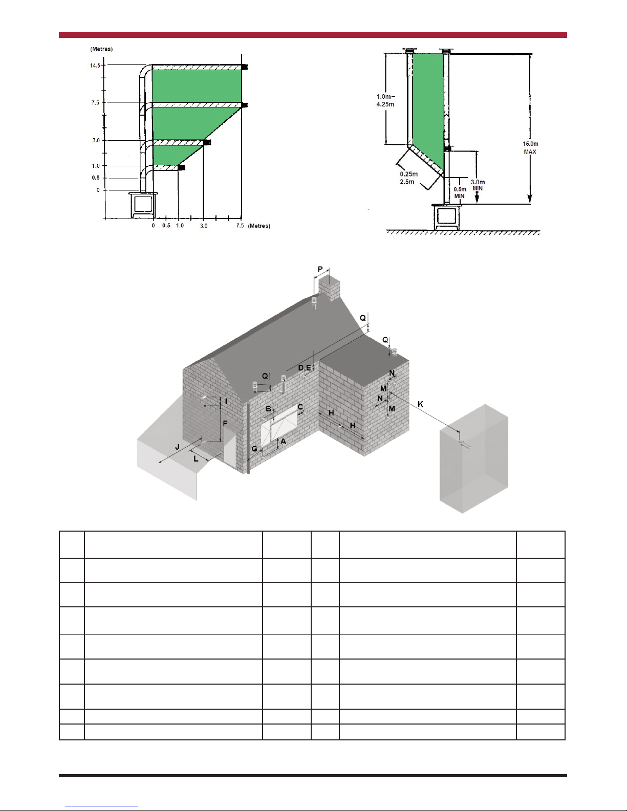
1. Flue terminals should be sited to ensure total
clearance of combustion products in
accordance with BS5440: Part 1 (latest
edition) - see Fig 7.
2. A terminal guard should be fitted to protect
against contact for any terminal less than 2
metres above any access from ground level,
balcony or flat roof.
3. The flue system must be constructed from
the appliance upwards, with all joints being
fully locked and sealed using the Waterford
Stanley specified parts.
4. Two types of flue terminals are available,
horizontal and vertical.
5. A Horizontal Flue Configuration should
comply with the following (see Fig 5):
* The horizontal flue run can not exceed the
vertical flue rise.
* Minimum vertical flue rise of 0.5 metres.
* Maximum vertical flue rise of 14.5 metres.
* Maximum horizontal flue run of 7.5 metres.
6. A Vertical Flue Configuration should
comply with the following (see Fig 6):
* Minimum vertical flue rise of 0.5 metres (from
top of unit before bend fitting).
* Maximum vertical flue rise of 15 metres.
* Maximum vertical flue rise reduced by 0.25
metres for every 45 degree bend fitted.
* Length of Vertical flue rise must be twice the
length of Horizontal flue run/offset.
GAS SOUNDNESS TESTING
Gas soundness testing should be in accordance
with I.S. 813 (I.E.) and B.S. 6891 (U.K.). Correct gas
pressure and proper gas supply pipe sizing is important for the successful performance of this stove.
Make sure that the plumber or gas supplier checks
the gas supply line and gas pressure at installation.
CAUTION: The stove must be isolated from gas
supply system during any gas soundness testing
at pressures in excess of 50 mbar
.
After testing gas supply pipe work, open the isolation
valve to stove and carry out gas soundness testing
at normal working pressure 20 mbar for natural gas
and 37 mbar for LPG models.
With the stove lighting carry out a leak test downstream of control using gas leak detection fluid.
CAUTION: If using a gas leak detection fluid for
leak testing DO NOT spray solution onto the control body.
7. Allow enough room above & to the side of
the stove to allow for connection & assembly
of the flue system to the top of the stove.
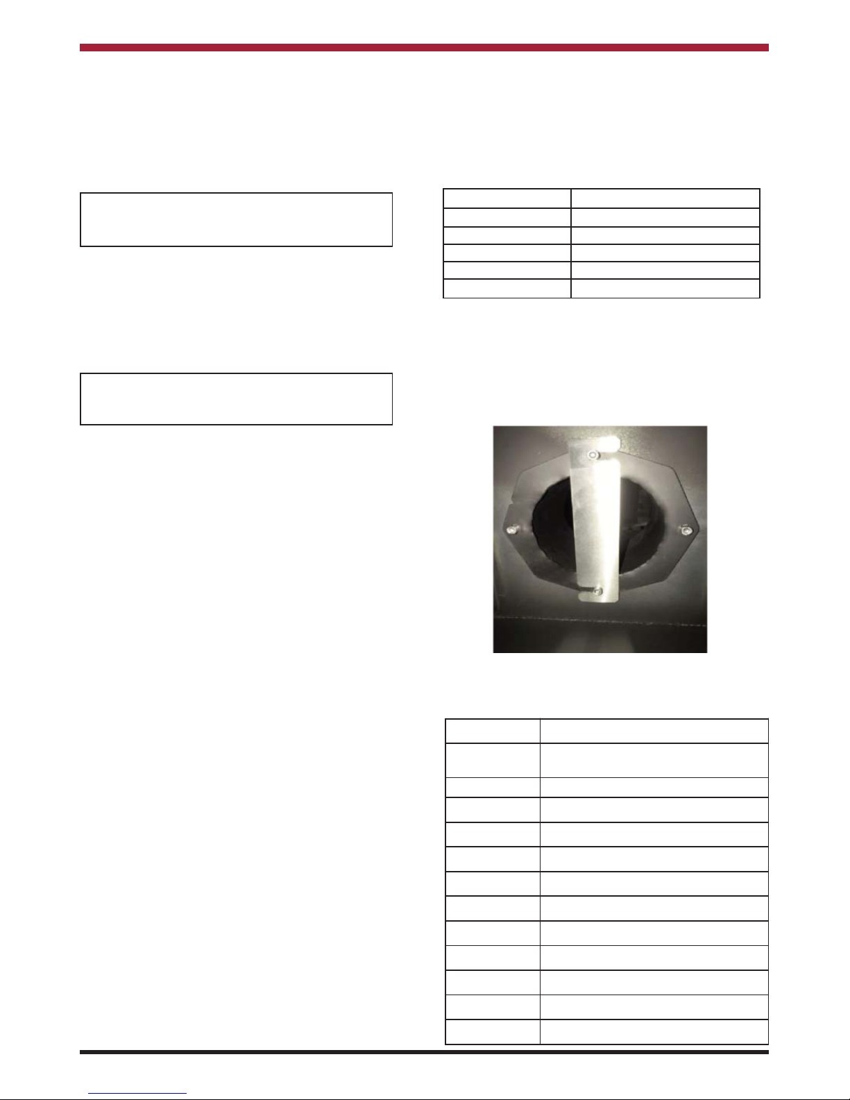
8. Depending on the flue height, a restrictor
plate may needed to be fitted to the inner
spigot (see Fig 4). The following details when
a restrictor plate needs to be fitted:
Part Code Description
34100610/9030 HORIZONTAL FLUE TERMINATION
KIT
34100654 VERTICAL FLUE TERMINATION KIT
37100438/9032 COMBUSTIBLE WALL KIT
34100405/9032 950mm STRAIGHT PIPE
34100404/9032 450mm STRAIGHT PIPE
34100403/9032 250mm STRAIGHT PIPE
34100402/9030 100mm STRAIGHT PIPE
34100441/9032 90 DEGREE BEND
34100421/9032 45 DEGREE BEND
45150169 FLAT ROOF FLASHING KIT
75000006 SLATE ROOF FLASHING KIT
45150173/9019 30-45 DEGREE TILE FLASHING KIT
The table below details the list of Waterford Stanley
Approved Flue Fittings for this stove.
Flue Height Flue Restrictor Plate
0 -2 metres None
2 - 4 metres 35mm Restrictor Plate
4 -6 metres 40mm Restrictor Plate
6 - 8 metres 30mm Restrictor Plate
8 - 15 metres None
Note: House position & wind direction can
cause variances in the above guide lines
and if the glass starts to blacken, soot
forms on the logs or the flame pattern is
too small in height, a flue restrictor plate
will need to be fitted.
Fig.4
Page 10
10
Fig.7
* In addition, the terminal should not be nearer than 300mm to an opening in the building fabric formed for the purpose of
accommodating a built in element such as a window frame.
Terminal Position Distance
(mm)
Terminal Position Distance
(mm)
A* Directly below an opening, air brick,
opening window etc.
600 I Above ground roof or balcony level 300
B Above an opening, air brick, opening win-
dow etc.
300 J From a surface facing the terminal 600
C Adjacent to an opening, air brick, open-
ing window etc.
400 K From a terminal facing the terminal 600
D Below gutters, soil pipes or drain pipes 300 L From an opening in the car port (e.g.
door, window into the dwelling)
1200
E Below eaves 300 M Vertically from a terminal on the same
wall
1500
F Below balconies of car port roof 600 N Horizontally from a terminal on the same
wall
300
G From a vertical drain pipe or soil pipe 300 P From a vertical structure on the roof 600
H From an internal or external corner 600 Q Above intersection with roof 150
Fig.5
Fig.6
Page 11

11
FUEL BED ARRANGEMENT
NOTE: When arranging the Media into the
Firebed, it is important that the Pilot Area
& the second thermocouple is kept clear
and that no Media enters the Pilot Shield
- see Fig 11.
Fig 7 details the various fuel bed media components
and they are arranged using the following procedure:
1. Remove the Top Panel from the Stove.
2. Remove the Front Panel by loosening the
two front fixing screws (see Fig 9) and lifting
the front upwards to remove.
3. Remove the firebox glass panel by removing
the fixing screws - see Fig 10.
Fig.8
4. Scatter the bags of embers over the top of
the burners as shown in Fig 11 keeping the
pilot area & second thermocouple clear.
5. Position Logs S1, S2 & S3 as shown in
Figure 12.
6. Position Logs S4 & S5 as shown in Figure
13.
7. Position Logs S6 & S7 as shown in Figure
14.
8. Position the Firecone/Log S8 as shown in
Figure 15.
9. Check the appliance for Pilot Ignition and
cross lighting ensuring that no material is
impinging the operation of the Pilot.
10. Refit the firebox glass panel, front panel &
top panel.
Fig.9
Fig.10
Fig.11
Fig.12
Fig.13
Pilot & Cross
Light kept clear
2nd Thermocouple
kept clear
Log S1
Log S2
Log S3
Log S5
Log S4
FRONT FIXING SCREWS
GLASS
FIXING
SCREWS
Page 12
12
Fig.14 Fig.15
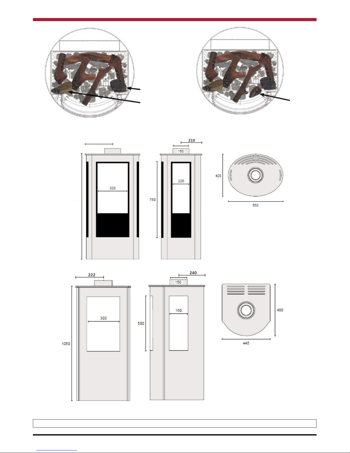
STOVE DIMENSIONS
F500 OVAL
F500 SLIM
Note: Dimensions stated are in millimetres unless otherwise stated and may be subject to a slight +/- variation.
Log S7
Log S6
Fircone /
Log S8
275
1060
Page 13
13
The Appliance Commissioning Checklist (see Page
6) must be filled out in conjunction with
conducting the following checks:
1. Pilot Ignition Check
A. Ignite the pilot light as described in the
Remote Control Operation Section.
B. Check that the pilot light flame stays light.
C. Extinguish the pilot light.
2. Main Burner Check
A. Ignite the pilot light as described in the
Remote Control Operation Section.
B. Turn on the main burner as described in the
Remote Control Operation Section.
C. Check that the pilot smoothly cross-lights to
the main burner and that the main burner &
pilot light stay alight.
D. Check the operation of the burners at the
various flame settings.
E. Extinguish the stove fully.
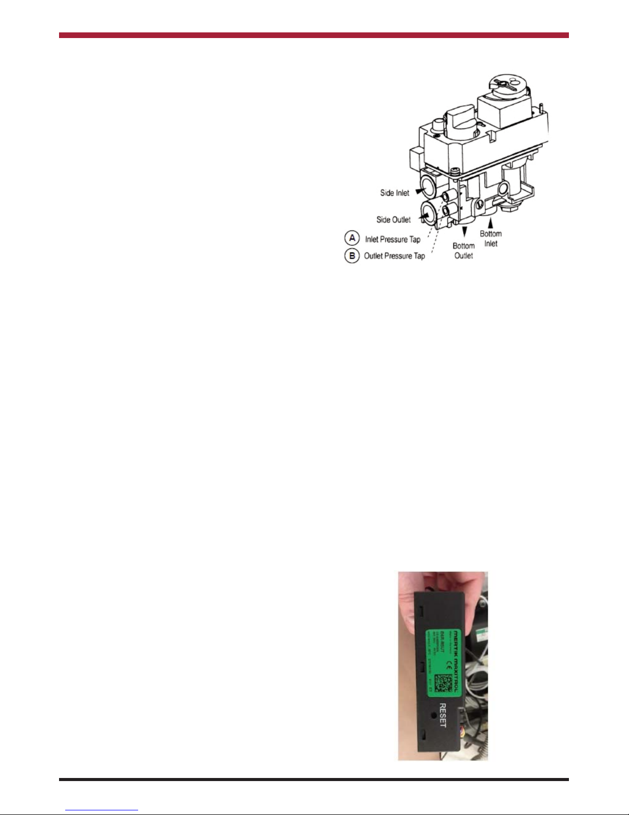
3. Pressure Check
The stove is preset to the correct heat inputs as listed in the Technical Data Section and the pressure
flows MUST not be adjusted. The inlet & burner
pressures must be checked using the following procedure (see Fig 16):
A. Turn off the gas valve on the stove.
B. Turn the screw on the Inlet Pressure Test
Point (A) on the gas valve by one turn (DO
NOT REMOVE) and connect a
manometer.
C. Check that the measured pressure is as the
prescribed supply pressure.
D. Perform the test when the appliance is
burning on full and with only the pilot alight.
E. If the pressure is low, check the gas supply
pipes are the correct size.
F. If the pressure is too high (more than 5 mbar
over) the appliance may be installed, but the
gas supply company should be contacted to
rectify same.
G. Retighten the screw on the Inlet Pressure
Test Point (A).
H. Turn the screw on the Burner Pressure
test point (B) on the gas valve by one turn
(DO NOT REMOVE) and connect a
manometer.
I. Check that the measured pressure is as
detailed in the Technical Data Section. The
measured value should be within +/- 10% of
the prescribed value.
J. Retighten the screw on the Burner Pressure
Test Point (B).
K. Test the system and gas valve for gas
soundness.
COMMISSIONING THE STOVE
Fig.16
4. Pairing the Remote Control
The remote control that comes with the stove should
already be paired to the burner. However if it
becomes un-paired or a you have had a replacement remote control, it can be paired to the burner
using the following procedure:
A. Turn on the Remote Control by pushing &
holding the power button (refer to Remote
Control Operation Section).
B. Hold the Reset Button on the side of the
gas control box under the burner unit until
it beeps twice (see Fig 17).
C. Press and hold the Down arrow button on
the Remote Control until you hear a single
beep.
D. Turn off the Remote Control by pushing the
power button.
E. Turn on the Remote Control by pushing &
holding the power button. If the remote has
been successful paired, the burner will ignite
after approximately ten seconds.
Fig.17
Page 14
14
TECHNICAL DATA
Gas Type G20
I
2H
, I
2E
G20
I
2E+
Supply Pressure mbar 20 20
Nominal Heat Input Gross (Hs) kW 8.0 8.0
Nominal Heat Input Nett (Hi) kW 7.7 7.7
Consumption
m3/hr
0.796 0.796
Burner Pressure (hot) mbar 19 19
Maximum Heat Output kW 5.5
Minimum Heat Output kW 1.8
Injector Marking 320 (Front) / 280 (Rear)
Pilot 446.1385.44
Efficiency Class/Efficiency 2 / 81%
Nox Class 5
NATURAL GAS
Gas Type G30/31 G31
I
3+
I
3P(37)
Supply Pressure mbar 28/37 37
Nominal Heat Input Gross (Hs) kW 7.5 8.5
Nominal Heat Input Nett (Hi) kW 7.2 7.2
Consumption
m3/hr
0.167 0.206
Burner Pressure (hot) mbar 27/36.7 36.7
Maximum Heat Output kW 5.0
Minimum Heat Output kW 1.7
Injector Marking 120 (Front) / 100 (Rear)
Pilot 446.1385.24
Efficiency Class/Efficiency 2 / 83%
Nox Class 5
LPG
FIRST TIME OPERATION
Before lighting the stove check with the installer that the installation work and commissioning checks described
previously have been carried out correctly. Ensure that all packaging, safety stickers & any protective wrapping
have been removed and that the glass has been cleaned including all fingerprints on the glass. As part of the
stove’s commissioning and handover the installer should demonstrate how to operate the stove correctly.
Ensure that the room is adequately ventilated the first time the stove is lit with the windows open. Run the stove
at the maximum setting for a few hours so that the paint gets an opportunity to fully cure. During this period it
is possible for some fumes and vapours to be given off as the paint completes the curement process.
Model
Energy
Efficiency
Class
Heat
Output to
Room
Heat
Output to
Water
Preferred
Fuel
Nominal Heat
Output
Net
Efficiency
Argon F500
Oval/Slim Nat Gas A 5.5kW NA
Natural
Gas 5.5kW 81%
Argon F500
Oval/Slim LPG
A 5.0kW NA LPG 5.0W 83%
Page 15
15
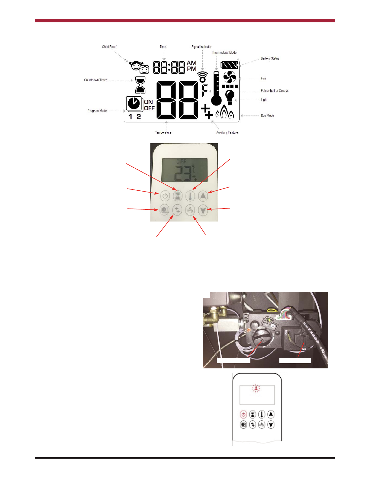
REMOTE CONTROL OPERATION
NOTE: If not using the mains adapter, it is recommended that the batteries are replaced in the gas
control box at the beginning of the heating season (see Battery Replacement Section). The
control box will provide frequent beeps for 3 seconds when the batteries are low. A low battery
indicator will be shown on the remote control display when the batteries are low on the remote.
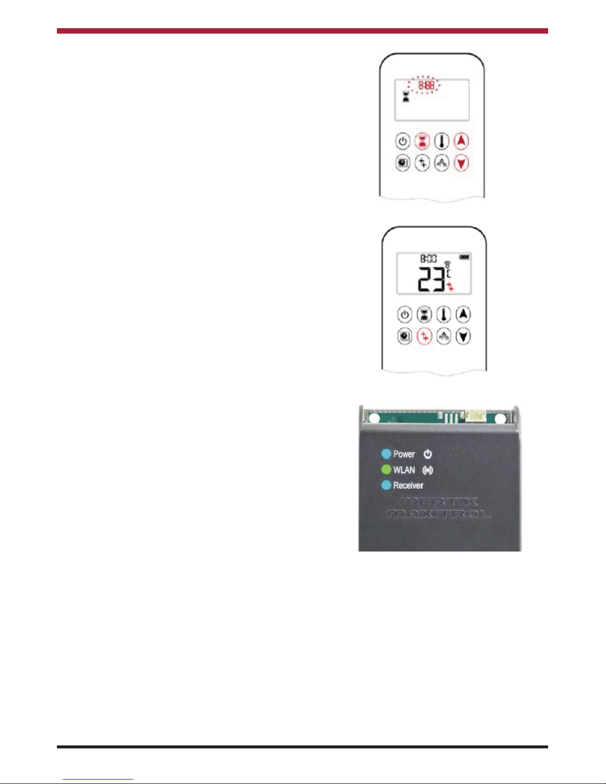
MANUAL MODE
To allow for remote control operation, make sure
that the Manual Knob on the gas valve is in the ON
(Full counterclockwise position) and the ON/OFF
switch is in the I (ON) position - refer to Fig 18.
Press & hold the Power Button two short beeps are
heard and a blinking series of lines appears on the
remote display (see Fig 19). This indicates that the
start sequence has begun during which the ignitor
will spark until the pilot flame lights. When the pilot
flame has lit and stabilised, the main burner will
ignite & light.
NOTE: If the pilot light does not stay lit
after several attempts, turn the
main valve knob to OFF and
contact your local service
engineer.
When the main burner flame has been established,
the flame height can be adjusted by (refer to Fig 20):
* Increase - Press & Hold the Up Arrow Button.
* Decrease - Press & Hold the Down Arrow
Button
Fig.19
Fig.18
POWER BUTTON
COUNTDOWN
TIMER
TEMPERATURE
BUTTON
UP ARROW
DOWN ARROW
PROGRAM
BUTTON
REAR BURNER BUTTON
ECO BUTTON
ON/OFF SWITCH
MANUAL KNOB
Page 16

16
Fig.20
Fig.21
Fig.22
Fig.23
The flame height can also be adjusted to the two
preset flame heights by:
* Low Fire (LO) - Double Click the Down Arrow
Button - see Fig 21.
* High Fire (HI) - Double Click the Up Arrow
Button - see Fig 22.
To turn off the stove, press & hold the Power Button
until the display shows OFF - see Fig 23.
NOTE: The burner must cool down for 30
seconds before reignition can be
attempted.
Fig.24
SETTING CELSIUS OR FAHRENHEIT
The remote control comes preset to show the temperature in Fahrenheit and it can be changed to
Celsius by pressing & holding the Power Button &
Timer Button simultaneously - see Fig 24.
NOTE: Choosing Fahrenheit results in a 12
hour clock being displayed and
choosing Celsius results in a 24 hour
clock being displayed.
Page 17

17
Fig.25
SETTING THE TIME
1. Press the Up Arrow Button & Down Arrow
Button simultaneously until the DAY flashes
on the display - see Fig 25.
2. Press the Up Arrow Button & Down Arrow
Button to select the number that corresponds
to the current day (e.g. 1 = Monday, 2 =
Tuesday, 3 = Wednesday etc).
3. Press the Up Arrow Button & Down Arrow
Button simultaneously until the HOUR
flashes on the display - see Fig 26.
4. Press the Up Arrow Button & Down Arrow
Button to select the current hour.
5. Press the Up Arrow Button & Down Arrow
Button simultaneously until the MINUTES
flashes on the display - see Fig 27.
6. Press the Up Arrow Button & Down Arrow
Button to select the current minute.
7. To confirm the settings, press and hold the
Up Arrow Button & Down Arrow
Button simultaneously until the display
returns to normal operating mode or the
display will return to standby mode if no
button is pressed.
Fig.27
Fig.26
AUTOMATIC OPERATION
The Argon Stove has three automatic operation
models:
A. Thermostatic Mode - The room temperature
is compared to the set temperature and the
flame height is automatically adjusted until
the set temperature is reached.
B. Program Mode - The stove operates for a set
period of time (Two ON/OFF periods per
day).
C. Eco Mode - The Flame Height modulates
from High to Low Flame settings. If the room
temperature is less than the set temperature,
the flame height is maintained at the High
setting. If the room temperature is greater
than the set temperature, the flame height is
maintained at the Low setting. Each cycle
will last approximately 20 minutes.
Thermostatic Mode
To activate the Thermostatic Mode, press the
Temperature Button. The Temperature Symbol will
be displayed , the preset temperature will be displayed briefly followed by the current room
temperature (see Fig 28).
To change the preset temperature, press and hold
the Temperature Button until the Temperature
Symbol is displayed and the preset temperature
flashes (see Fig 29). Press the Up Arrow Button &
Down Arrow Button to select the desired temperature setting and press & hold the Temperature
Button to confirm the setting until the display returns
to Thermostatic Mode.
To deactivate the Thermostatic Mode & return to
Manual Mode, press the Temperature Button until
the Temperature Symbol disappears.
Page 18

18
Fig.28
Fig.29
Program Mode
The following procedure should be used when
setting the Temperature and Timer Program:
1. To set the temperature, press & hold the
Program Button until the Program
Mode display flashes ON & the set
temperature is displayed. Then the
Program Mode display flashes OFF & the set
temperature flashes (see Fig 30).
2. Press the Up Arrow Button & Down Arrow
Button to select the desired temperature
setting.
3. Press the Program Button to confirm the
temperature setting.
The program mode can be set to operate as follows:
* ALL - The same programme every day
* SA:SU - The same programme for weekdays
& a different setting for Saturday & Sunday
* 1,2,3,4,5,6,7. - Different setting for each day.
4. Having confirmed the temperature setting,
the Program Mode symbol & ALL will flash
on the display - see Fig 31. Press the Up
Arrow Button & Down Arrow Button to select
the desired setting (e.g. ALL, SA:SU or
1,2,3,4,5,6,7).
5. To confirm press the Program Button.
6. The Program 1 ON setting will be displayed
with the hour setting flashing - see Fig 32.
Press the Up Arrow Button & Down Arrow
Button to select the desired ON hour.
7. To confirm press the Program Button.
8. The minute setting will flash and press the
Up Arrow Button & Down Arrow Button to
select the desired ON minute.
9. To confirm press the Program Button.
10. The Program 1 OFF setting will be displayed
with the hour setting flashing - see Fig 33.
Press the Up Arrow Button & Down Arrow
Button to select the desired OFF hour.
11. To confirm press the Program Button.
12. The minute setting will flash and press the
Up Arrow Button & Down Arrow Button to
select the desired OFF minute.
13. To confirm press the Program Button.
14. The Program 2 ON setting will be displayed
with the hour setting flashing & repeat steps
6 to 13 to set the times for Program 2. If not
using a time period, set the ON & OFF times
to the same time.
15. If you have selected SA:SU or 1,2,3,4,5,6,7,
adjust the day setting (1,2,3,4,5,6,7) using
the Up Arrow Button & Down Arrow Button
and follow steps 6 to 13 to set the times for
each day.
Fig.30
Fig.31
Page 19

19
Fig.32
Fig.33
To activate the Program Mode, press the Program
Button. The Program Mode Symbol will be
displayed as shown in Fig 34.
To deactivate the Program Mode & return to Manual
Mode, press the Program Button and then press
either the Up Arrow Button or Down Arrow Button.
Eco Mode
To activate the Eco Mode, press the Eco Button. The
Eco Mode Symbol will be displayed as shown in Fig
35.
To deactivate the Eco Mode & return to Manual
Mode, press the Eco Button.
ADDITIONAL OPERATIONAL FEATURES
The Argon Stove has three standard additional operational features:
A. Child Lock
B. Countdown Timer
C. Rear Burner Operation
Child Lock
To activate the Child Lock and disable the remote
control (with the exception of the OFF function),
press the Power Button and Down Arrow Button
simultaneously until the Child Lock Symbol is
displayed - see Fig 36.
To deactivate the Child Lock & return to Manual
Mode, press the Power Button and Down Arrow
Button simultaneously until the Child Lock Symbol
disappears.
Fig.34
Fig.35
Fig.36
Page 20
20
Fig.37
Fig.38
Countdown Timer
The Countdown Timer allows for the Stove to be
operated for a set period (up to maximum of 9 hours
& 50 minutes) provided the Stove is set to Manual,
Thermostatic or Eco Modes.To set the Countdown
Timer:
1. Press & hold the Countdown Timer Button
until the Countdown Timer Symbol is
displayed and the hour setting flashes- see
Fig 37.
2. Press the Up Arrow Button & Down Arrow
Button to select the desired hour operating
period.
3. Press the Countdown Timer Button to
confirm the setting.
4. The minute setting will flash and press the
Up Arrow Button & Down Arrow Button to
select the desired minute operating period.
5. Press the Countdown Timer Button to
confirm the setting. The Countdown Timer
Symbol & Timer Clock will be shown on the
remote display with the remaining time on
the period shown.
To deactivate the Countdown Timer, press & hold
the Countdown Timer Button until the Countdown
Timer Symbol & Countdown Timer Clock disappears.
Rear Burner Operation
The Rear Burner can be turned On or Off as desired
by pressing the Rear Burner Button until the Rear
Button Symbol is displayed and the rear burner is
ignited (see Fig 38). To deactivate, press the Rear
Burner Button until the Rear Button Symbol disappears.
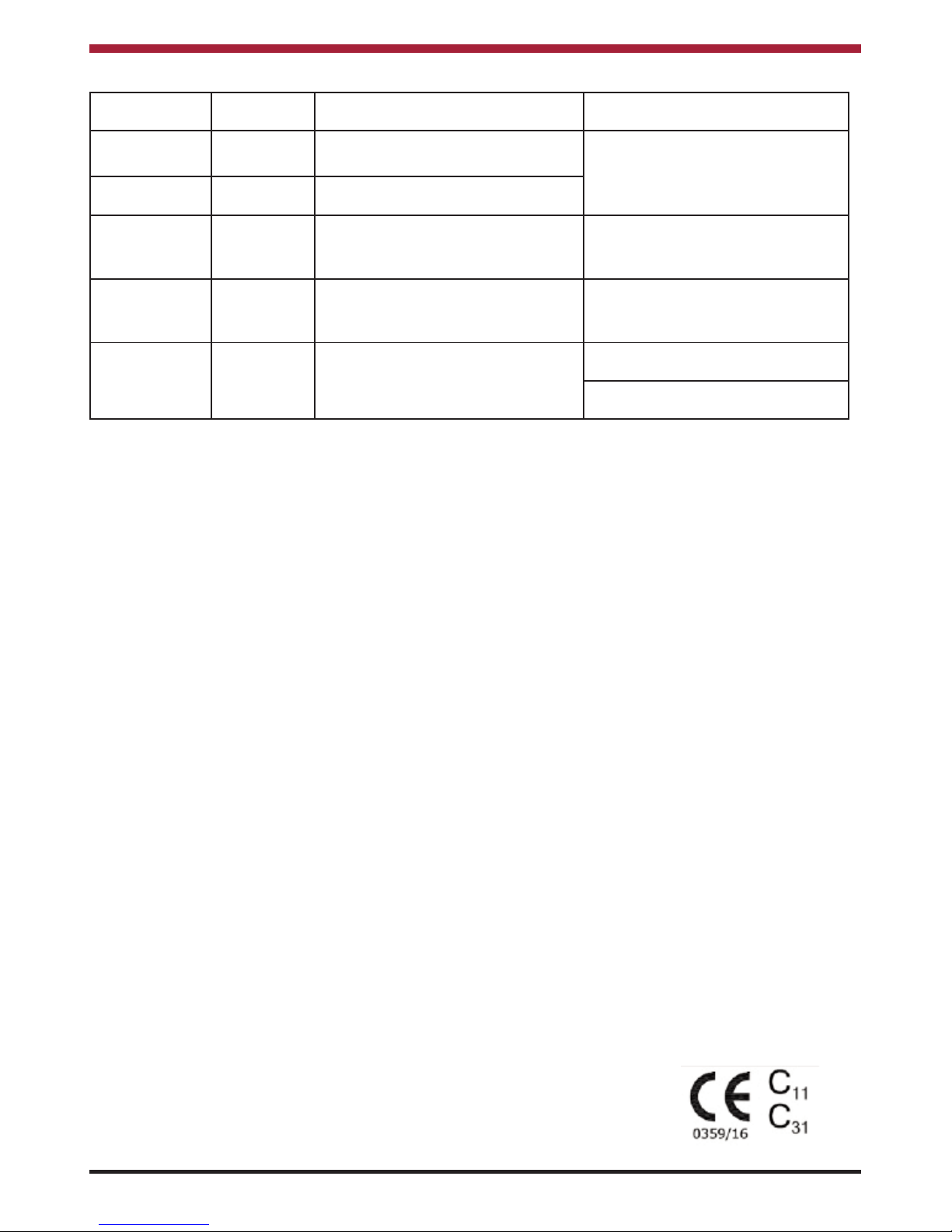
WI-FI OPERATION
The Argon Stove can be operated remotely using
the myfire app by connecting the optional myfire WiFi Box (Part Code: B6R-W) and connecting same to
a Home Network (Wi-Fi Router). The myfire Wi-Fi
Box will operate for a short period of time using batteries but if mains power is lost for a period of time,
it is recommended to disconnect the Wi-Fi Box from
the Gas Valve Control Box.
To set-up the myfire Wi-Fi Box, use the following
procedure:
1. Connect the data cable to the Gas Valve
Control Box & myfire Wi-Fi Box (refer to
Wiring Diagram).
2. Connect the Mains Adaptor to the Gas
Control Valve. After 30 seconds the myfire
Wi-Fi Box goes into Access Point Mode)
green LED flashes - see Fig 39.
Fig.39
Page 21

21
3. Download the myfire App from Apple App
Store or Google Play Store.
4. Start App setup.
5. Choose language, temperature (Celsius or
Fahrenheit) and time format (12 or 24 hour).
6. Complete the registration process and Login
to the App.
7. Touch the + icon and a message will tell you
to go to your smart device Wi-Fi settings.
8. Touch myfire_WiFi-Box_<number>.
9. Enter the password “MYFIREPLACE”.
10. Select a name for your stove.
11. Type in the name (SSID) of your Wi-Fi router.
12. Type in the password of your Wi-Fi router.
13. Touch “Connect” button.
14. After successful connection a pop-up will tell
you to go to your smart device Wi-Fi settings.
Touch “OK” if the settings are correct.
15. After confirming fireplace settings touch
“Finish”.
16. Touch “Start App” to finish the installation &
setup process.
NOTE: If any of the Automatic Operation
Modes are activated using the App,
“APP” will be displayed on the
Remote Control.
For further instructions & video on how to set-up the
myfire App, see http://myfireapp.com/en/setup/.
CLEANING
Cleaning should be done when the stove is cold by
removing any dust or dirt using a dry cloth. Do not
use any water on the matt black finish as this will
cause it to discolour. It is recommended to clean the
stove of any dust & debris regularly and especially if
the stove has not been used for some time.
MAINTENANCE
This stove must be inspected and serviced once
a year by a qualified/competent Gas Engineer.
CO ALARM
The fitting of CO Alarms in the same room as the
appliance is a compulsory requirement under current Building Regulations. For ROI an additional CO
Alarm must be fitted either inside each bedroom or
within 5 metres of the bedroom door, refer to
Building Regulations Part J. Further guidance on the
installation of a carbon monoxide alarm is available
in BS EN 50292:2002 and from the alarm manufacturers instructions.
WARNING NOTE:
Properly installed, operated and maintained this
stove will not emit fumes into the dwelling. In the
event of a gas escape or if you can smell gas then
the following immediate action should be taken:
(a) Immediately turn off the gas supply at the
meter/emergency control valve.
(b) Extinguish all sources of ignition.
(c) Do not smoke.
(d) Do not operate any electrical light or power
switches (ON or OFF).
(e) Ventilate the building(s) by opening doors &
windows.
(f) Ensure access to the premises can be made.
Please report the incident immediately to Gas
Networks Ireland (1850 20 50 50), National Gas
Emergency Service Call Centre (0800111999 for
UK or 0800002001 for Northern Ireland) or in the
case of LPG, the gas supplier whose details can be
found on the bulk storage vessel or cylinder.
The gas supply must not be used until remedial
action has been taken to correct the defect and the
installation has been recommissioned by a competent person.
Provision of an alarm must not be considered a
substitute for either installing the appliance
correctly or ensuring regular servicing and
maintenance of the appliance and chimney
system.
WARNING:-
If the CO Alarm sounds unexpectedly:-
1. Turn off the stove immediately.
2. Open Doors and windows to ventilate the
room and then leave the premises.
Page 22

22
BATTERY REPLACEMENT
The Gas Valve Control Box requires four AA
Batteries which are fitted by removing the front
cover and inserting the batteries into the housing as
shown in Fig 40.
The Remote Control requires two AAA Batteries
which are fitted by removing the back cover and
inserting the batteries into the housing as shown in
Fig 41.
NOTE: It is recommended to use Duracell
Ultra Power alkaline batteries.
Rechargeable batteries are not to be
used. Under normal conditions
batteries should last approximately
12 months.
SERVICING
Before carrying out any maintenance, ensure
that the Stove is cold and isolate the main gas
supply.
ALL SERVICING & REPAIR WORK MUST BE
CARRIED OUT BY A QUALIFIED/COMPETENT
GAS ENGINEER.
The following is the recommended procedure for
servicing the Stove:
1. Remove the Top Panel from the Stove.
2. Remove the Front Panel by loosening the
two front fixing screws (see Fig 9) and lifting
the front upwards to remove.
3. Remove the firebox glass panel by removing
the fixing screws - see Fig 10.
4. Carefully remove the Ceramic Logs and
Embers.
5. Use a vacuum cleaner and a soft brush to
clean the pilot assembly and both injectors. It
may be easier to access the Injector by
removing the throttle.
NOTE: NEVER MODIFY OR BEND THE
THERMOCOUPLE.
6. Turn on the gas supply and check for leaks.
7. Check the operation of the burners & pilot.
8. Clean the Ceramic Logs & Embers external
to the building using a soft brush and a
vacuum cleaner. Any damaged parts should
be replaced.
9. Replace the Ceramic Logs and Embers see Fuel Bed Arrangement Section.
10. Clean the Firebox Glass Panel & refit same.
11. Refit the Front & Top Panels.
12. Check the flue system & terminal ensuring
that the terminal vent is fully clear.
Fig.40
Fig.41
13. Light the stove and test the pressure
settings (see Pressure Check).
14. Test the gas valve and gas system for
soundness.
15. Check the safe operation of the Stove.
16. Complete the Service Records Log on the
back of the manual.
Page 23

WIRING DIAGRAM
23
Page 24

EXPLODED VIEW - F500 OVAL
24
No. Description Part Number
1 Complete Burner - Nat Gas SW-DB-2TC-NG
Complete Burner - LPG SW-DB-2TC-LPG
2 Inner Flue Collar SW-PFC-INC-001
3 Outer Flue Collar SW-PFC-OFC-002
4 Top Plate Filler Piece SW-OIH-TPF-027
5 Grate Tray SW-UIH-GTB-004
6 Delayed Ignition Gasket SW-UIH-CPG-005
7 Delayed Ignition Pin SW-UIH-DIP-006
8 Delayed Ignition Flap SW-UIH-DIF-007
9 Front Glass Upper Clamp SW-OIH-FGUC-028
10 Side Glass Retaining Bracket SW-UIH-SGRB-029
11 Back Panel SW-OIH-OBP-030
12 Front Panel SW-OIH-FDP-031
13 Outer Side Glass SW-OIH-SGC-032
14 Front Glass Gasket SW-UIH-FGG-013
15 Firebox Front Glass SW-UIH-FGF-014
16 Firebox Glass Fixing Bracket SW-UIH-FGFB-015
17 Firebox Side Glass SW-UIH-FSG-016
18 Retainer Bar Bracket SW-UIH-RBB-017
19 Retaining Bar SW-OIH-SSRB-033
20 Front Glass SW-OIH-FGC-034
21 Top Panel SW-OIH-STP-035
22 Outer Shell SW-UIH-OBS-036
No. Description Part Number
23 Pilot Assembly - Nat Gas SW-UMM-PLA-NG
Pilot Assembly - LPG SW-UMM-PLA-LPG
24 Electrode SW-UMM-EL-022
25 Electrode Lead SW-UMM-ELL-023
26 Thermocouple SW-UMM-TCF-024
27 Gas Valve - Nat Gas SW-UMM-GV60-NG
Gas Valve - LPG SW-UMM-GV60-LPG
28 2nd Thermocouple Guard SW-UIH-SS2TCG-037
29 Main Thermocouple Guard SW-UIH-SSMTCG-038
30 Main Thermocouple Shield SW-UIH-SSMTCS-039
31 Side Panel SW-OIH-SPC-040
32 Firebox Side Glass Bracket SW-UIH-SGB-041
Front Injector - Natural Gas SW-UMM-FRI-NG
Front Injector - LPG SW-UMM-FRI-LPG
Rear Injector - Natural Gas SW-UMM-RRI-NG
Rear Injector - LPG SW-UMM-RRI-LPG
Ceramic Log Pack SW-UIH-CRP-025
Ember Pack SW-UIH-CEP-026
Remote Control SW-UMM-RC-SY2
Receiver Unit SW-UMM-RU2T-SY2
Wiring Loom SW-UMM-WRC-SY2
Mains Adaptor G60-ZMA3
myfire Wi-Fi Box B6R-W
Page 25

EXPLODED VIEW - F500 SLIM
24
No. Description Part Number
1 Complete Burner - Nat Gas SW-DB-2TC-NG
Complete Burner - LPG SW-DB-2TC-LPG
2 Inner Flue Collar SW-PFC-INC-001
3 Outer Flue Collar SW-PFC-OFC-002
4 Top Plate Filler Piece SW-OIH-TPF-003
5 Grate Tray SW-UIH-GTB-004
6 Delayed Ignition Gasket SW-UIH-CPG-005
7 Delayed Ignition Pin SW-UIH-DIP-006
8 Delayed Ignition Flap SW-UIH-DIF-007
9 Front Glass Upper Clamp SW-SIH-FGUC-008
10 Front Glass Lower Clamp SW-SIH-FGLC-009
11 Bottom Door SW-SIH-FBD-010
12 Front Panel SW-SIH-FDP-011
13 Bottom Door Hinge SW-SIH-BDH-012
14 Front Glass Gasket SW-UIH-FGG-013
15 Firebox Glass SW-UIH-FGF-014
16 Firebox Glass Fixing Bracket SW-UIH-FGFB-015
17 Side Glass SW-UIH-FSG-016
18 Retainer Bar Bracket SW-UIH-RBB-017
19 Retaining Bar SW-SIH-SSRB-018
20 Front Glass SW-SIH-FGC-019
21 Top Panel SW-SIH-STP-020
No. Description Part Number
22 Outer Shell SW-SIH-OBW-021
23 Pilot Assembly - Nat Gas SW-UMM-PLA-NG
Pilot Assembly - LPG SW-UMM-PLA-LPG
24 Electrode SW-UMM-EL-022
25 Electrode Lead SW-UMM-ELL-023
26 Thermocouple SW-UMM-TCF-024
27 Gas Valve - Nat Gas SW-UMM-GV60-NG
Gas Valve - LPG SW-UMM-GV60-LPG
28 Main Thermocouple Guard SW-UIH-SSMTCG-038
29 Main Thermocouple Shield SW-UIH-SSMTCS-039
2nd Thermocouple Guard SW-UIH-SS2TCG-037
Front Injector - Nat Gas SW-UMM-FRI-NG
Front Injector - LPG SW-UMM-FRI-LPG
Rear Injector - Natural Gas SW-UMM-RRI-NG
Rear Injector - LPG SW-UMM-RRI-LPG
Ceramic Log Pack SW-UIH-CRP-025
Ember Pack SW-UIH-CEP-026
Remote Control SW-UMM-RC-SY2
Receiver Unit SW-UMM-RU2T-SY2
Wiring Loom SW-UMM-WRC-SY2
Mains Adaptor G60-ZMA3
myfire Wi-Fi Box B6R-W
Page 26

26
SERVICE RECORDS
1ST SERVICE
Date of Service:........................................................
Next Service Due:.....................................................
Signed: .....................................................................
RGI/Gas Safe Registration No/Stamp:
3RD SERVICE
Date of Service:........................................................
Next Service Due:.....................................................
Signed: .....................................................................
RGI/Gas Safe Registration No/Stamp:
5TH SERVICE
Date of Service:........................................................
Next Service Due:.....................................................
Signed: .....................................................................
RGI/Gas Safe Registration No/Stamp:
7TH SERVICE
Date of Service:........................................................
Next Service Due:.....................................................
Signed: .....................................................................
RGI/Gas Safe Registration No/Stamp:
2ND SERVICE
Date of Service:........................................................
Next Service Due:.....................................................
Signed: .....................................................................
RGI/Gas Safe Registration No/Stamp:
4TH SERVICE
Date of Service:........................................................
Next Service Due:.....................................................
Signed: .....................................................................
RGI/Gas Safe Registration No/Stamp:
6TH SERVICE
Date of Service:........................................................
Next Service Due:.....................................................
Signed: .....................................................................
RGI/Gas Safe Registration No/Stamp:
8TH SERVICE
Date of Service:........................................................
Next Service Due:.....................................................
Signed: .....................................................................
RGI/Gas Safe Registration No/Stamp:
Page 27

27
FAULT FINDING - GENERAL
ISSUE POSSIBLE CAUSE SOLUTION
Remote Control
not working
Remote Control Batteries Low. Replace Batteries (See Battery Replacement Section
Gas Control Valve Batteries Low. Replace Batteries (See Battery Replacement Section
Optional Mains Adapter not operating correctly.
Check Mains Adapter.
Check link between remote &
receiver.
Repair Remote Control (see Pairing Remote Control
Section)
Pilot will not light.
No Gas Check Gas Supply.
Insufficient Gas Pressure Check Inlet & Outlet Pressures (see Pressure Check
Section).
Blocked Pilot Injector. Clear debris from Pilot Injector.
ON/OFF Switch in OFF (O)
Position.
Push switch to ON Posiiton (see Figure 18).
No Ignition Spark.
Check connection between ignition cable & electrode.
Check electrode spark gap and ensure electrode is
not shorting on burner body.
Replace electrode.
Replace ignition cable.
Main Burner will
not light
Thermocouple & Switch connections reversed.
Check connections to Gas Valve Control Box.
Magnet unit not operating properly. Replace Gas Valve.
Short between Interlopers and
Switch cable.
Check connection to Interrupter.
Insufficient Gas Pressure Check Inlet & Outlet Pressures (see Pressure Check
Section).
Resistance in thermocouple circuit
too high.
Check thermocouple cable.
Not enough heat on thermocouple. Check position of pilot to thermocouple and intensity
of pilot flame.
Low voltage from thermocouple.
Replace thermocouple (Hand tight +1/4 turn max)
Short because thermocouple is
damaged or not centreed.
Ignition stops. No reaction to transmitter command.
Press Reset Button on Gas Valve Control Box.
Main Burner Cuts
out after lighting
Too much draft at pilot Check Installation.
Page 28
28
Supplied by
Waterford Stanley Ltd.,
Unit 401-403, IDA Industrial Estate, Cork Road,
Waterford, Ireland.
Tel: (051) 302300 Fax (051) 302315
N00787AXX Rev: 001 SG 040718
FAULT CODES - REMOTE CONTROL
FAILURE
CODE
DURATION
DISPLAYED
SYMPTOM POSSIBLE CAUSE
F04 4 sec No Pilot Flame within 30 seconds.
See “Pilot Light will not Light” on
Fault Finding Section
F06 4 sec 3 Failed Ignition Sequences within 5
minutes.
F09 4 sec Fire is not responding. Remote Control not synced to
Burner. (See Pairing the Remote
Control Section)
F40
(Battery Symbol
shown)
Permanent Low Battery on Remote Control See Battery Replacement Section.
F46 4 sec Fire is not responding or only
responding intermittently.
Bad Connection between Remote
Control & Burner.
Battery Low on Gas Control Valve
(See Battery Replacement Section.)
 Loading...