

Page 1
Argon Built In
INSTALLATION AND OPERATING INSTRUCTIONS
The complete installation must be done in accordance with current Standards and Local Codes. The
instructions in this manual must be followed to ensure safe operation of the appliance. It should be
noted that the requirements and this publication may be superseded during the life of the stove.
PLEASE RETAIN
MODELS: ARBI100/ARBI130
AFFIX SERIAL
NO. LABEL
The serial number above must be retained and will be required when
registering the product guarantee or making a warranty claim.
Page 2

TABLE OF CONTENTS
PAGE NO.
1. Stanley Appliance Warranty . . . . . . . . . . . . . . . . . . . . . . . . . . . . . . . . . . . . . . . . . . . . . . . . . . . . . . . 3
2. Important Operation/ Maintenance Notes . . . . . . . . . . . . . . . . . . . . . . . . . . . . . . . . . . . . . . . . . . . .4
3. Installation & Operating Instructions . . . . . . . . . . . . . . . . . . . . . . . . . . . . . . . . . . . . . . . . . . . . . . . . . 5
4. Locating the Unit . . . . . . . . . . . . . . . . . . . . . . . . . . . . . . . . . . . . . . . . . . . . . . . . . . . . . . . . . . . . . . . . 5
5. Unpacking & Testing . . . . . . . . . . . . . . . . . . . . . . . . . . . . . . . . . . . . . . . . . . . . . . . . . . . . . . . . . . . . . 5
6. Installation - Built In . . . . . . . . . . . . . . . . . . . . . . . . . . . . . . . . . . . . . . . . . . . . . . . . . . . . . . . . . . . . . . 5
7. Product Dimensions . . . . . . . . . . . . . . . . . . . . . . . . . . . . . . . . . . . . . . . . . . . . . . . . . . . . . . . . . . . . . 6
8. Technical Data . . . . . . . . . . . . . . . . . . . . . . . . . . . . . . . . . . . . . . . . . . . . . . . . . . . . . . . . . . . . . . . . . . 7
9. Commissioning & Handover . . . . . . . . . . . . . . . . . . . . . . . . . . . . . . . . . . . . . . . . . . . . . . . . . . . . . . . 7
10. Operation . . . . . . . . . . . . . . . . . . . . . . . . . . . . . . . . . . . . . . . . . . . . . . . . . . . . . . . . . . . . . . . . . . . . . . 7
11. Manual Operation . . . . . . . . . . . . . . . . . . . . . . . . . . . . . . . . . . . . . . . . . . . . . . . . . . . . . . . . . . . . . . . 8
12. Remote Control Operation . . . . . . . . . . . . . . . . . . . . . . . . . . . . . . . . . . . . . . . . . . . . . . . . . . . . . . . . 8
13. Heater Operation . . . . . . . . . . . . . . . . . . . . . . . . . . . . . . . . . . . . . . . . . . . . . . . . . . . . . . . . . . . . . . . . 9
14. Flame Operation . . . . . . . . . . . . . . . . . . . . . . . . . . . . . . . . . . . . . . . . . . . . . . . . . . . . . . . . . . . . . . . . 9
15. Setting the Time & Day (24 Hour Clock) . . . . . . . . . . . . . . . . . . . . . . . . . . . . . . . . . . . . . . . . . . . . . . 9
16. Setting the Programmer . . . . . . . . . . . . . . . . . . . . . . . . . . . . . . . . . . . . . . . . . . . . . . . . . . . . . . . . . . 9
17. Open Window Function . . . . . . . . . . . . . . . . . . . . . . . . . . . . . . . . . . . . . . . . . . . . . . . . . . . . . . . . . . . 10
18. Safety Cut-Out . . . . . . . . . . . . . . . . . . . . . . . . . . . . . . . . . . . . . . . . . . . . . . . . . . . . . . . . . . . . . . . . . 11
19. Battery Replacement - Remote Control . . . . . . . . . . . . . . . . . . . . . . . . . . . . . . . . . . . . . . . . . . . . . . 11
20. Cleaning . . . . . . . . . . . . . . . . . . . . . . . . . . . . . . . . . . . . . . . . . . . . . . . . . . . . . . . . . . . . . . . . . . . . . . 11
21. Wiring Diagram . . . . . . . . . . . . . . . . . . . . . . . . . . . . . . . . . . . . . . . . . . . . . . . . . . . . . . . . . . . . . . . . . 11
22. Exploded View . . . . . . . . . . . . . . . . . . . . . . . . . . . . . . . . . . . . . . . . . . . . . . . . . . . . . . . . . . . . . . . . . 12
2
Page 3

3
STANLEY APPLIANCE WARRANTY
CONDITIONS OF WARRANTY
Your Stanley Appliance is guaranteed against any part that fails (under normal operating conditions) for a two year period from the date of installation of the appliance. If the unit is not installed within six months of date of purchase, the
warranty will commence six months from the date of purchase.
All warranty claims must be reported to the Waterford Stanley Service Department and must be submitted with the product serial number (located on the front of this manual), date of purchase, proof of purchase (if requested) and details
of the specific nature of the problem.
The warranty is given only to the original consumer/purchaser only and is non-transferable. The appliance must be
installed by a suitable qualified person and installed as per the requirements of the manual. Failure to comply with the
Installation Requirements or Building Regulations will void your warranty. Waterford Stanley reserve the right to replace
any part due to manufacturing defect that fails within the warranty period under the terms of the warranty. The unit must
be used for normal domestic purposes only and in accordance with manufacturer's operation instructions.
LIMITS OF LIABILITY
The warranty does not cover:
* Bulbs and Batteries.
* Special, incidental or consequential damages, injury to persons or Property, or any other consequential loss.
* Any issue caused by negligence, misuse, abuse or circumstances beyond Waterford Stanley’s control.
* Any issue with wear and tear, modification, alteration, or servicing by anyone other than an authorized service
engineer.
* Damage resulting from installation & usage where the appliance has not been installed or used in accordance
with the installation or operation instructions or if the installation does not conform to local building, fire &
safety regulations.
* Damage caused to the unit while in transit.
* Damage caused by storing the unit in a damp, unheated environment.
* Aesthetic damage & missing parts on units purchased off display.
* Removal & re-installation costs.
Note: Adequate clearance must be maintained around the appliance to ensure the ease of part removal in the possible event of their damage/failure. Waterford Stanley are not responsible for any costs incurred in the removal of items
installed in the vicinity of the appliance that have to be moved to facilitate a part replacement.
Page 4

IMPORTANT OPERATION / MAINTENANCE NOTES
Now that your Stanley Appliance is installed and no doubt you are looking forward to the many comforts it will
provide, we would like to give you some tips on how to get the best results from your unit.
1. Carefully read all instructions before using this unit.
2. The unit is hot when in use. To avoid burns, do not let bare skin touch hot surfaces. The grill at the
bottom of the unit becomes hot during heater operation.
3. Keep combustible materials, such as furniture, pillows, bedding, papers, clothes and curtains at least 3
feet (0.9m) from the front of the unit.
4. Extreme caution is necessary when any heater is used by or near children or invalids and
whenever the unit is left operating and unattended.
5. Always unplug the unit when not in use.
6. Do not operate this unit with a damaged cord or plug, or if the unit has malfunctioned, or if the unit has
been dropped or damaged in any manner.
7. Do not use the unit for other than its intended use. Do not use outdoors.
8. This unit is not intended for use in bathrooms, laundry areas and similar indoor locations. Never
locate this unit where it may fall into a bathtub or other water container.
9. Do not install the unit on a surface which may restrict air circulation beneath the unit.
10. Do not run the mains cord under carpeting. Do not cover the cord with throw rugs, runners or the like.
Arrange the cord away from traffic area and where it will not be tripped over.
11. To disconnect the unit turn controls to off, then remove plug from outlet.
12. Do not insert or allow foreign objects to enter any ventilation or exhaust opening as this may cause
an electric shock or fire, or damage the heater.
13. To prevent a possible fire, do not block the air intake or exhaust in any manner. Do not use on soft surfaces, like a carpet, where openings may become blocked.
14. All electrical heaters have hot and arcing or sparking parts inside. Do not use it in areas where
gasoline, paint, or flammable liquids are used or stored or where the unit will be exposed to
flammable vapours.
15. Do not modify this unit. Use it only as described in this manual. Any other use not recommended by the
manufacturer may cause fire, electric shock or injury to persons.
16. Avoid the use of an extension cord because the extension cord may overheat and cause a risk of
fire.
17. Do not strike the glass.
18. Always use a certified electrician should new circuits or outlets be required.
19. Always use properly grounded, fused and polarised outlets. DO NOT cut off the plug and hardwire
directly into the mains or via a fused fixed spur.
20. Always use ground fault protection where required by electrical code.
21. Always disconnect power before performing any cleaning, maintenance or relocation of the unit.
22. When transporting or storing the unit and mains cord, keep in a dry place, free from excessive vibration
and store so as to avoid damage.
23. To prevent possible fire, do not burn wood or other materials in this heater.
24. The unit may emit a slight, harmless odour and smoke when first used. This odour and smoke
is normal and it is caused by the initial heating of internal heater parts and will not occur again.
25. Do not use the unit in small rooms when they are occuppied by persons not capable of leaving the
room on their own, unless constant supervision is provided.
26. Children of less than 3 years should be kept away from the unit unless constantly supervised.
27. Children aged from 3 years and less than 8 years shall only switch on/off the unit provided that it has
been placed or installed in its intended normal operating position and they have been given supervision
or instruction concerning the use of the unit in a safe way and understand the hazards involved. Children
aged from 3 years and less than 8 years shall not plug in, regulate and clean the appliance or perform
user maintenance.
28. This unit can be used by children aged from 8 years & above and persons with reduced physical,
sensory or mental capabilities or lack of experience & knowledge if they have been given supervision
or instruction concerning the use of the unit in a safe way and understand the hazards involved. Children
shall not play with the unit. Cleaning and user maintenance shall not be made by children without
supervision.
4
Page 5

5
INSTALLATION & OPERATING INSTRUCTIONS
LOCATING THE UNIT
Before commencing installation of the unit consideration should be given to the following:
1. Position in the area to be heated, central
locations are usually best.
2. Allowances for proper clearances to
combustibles (see Fig 1) .
3. Allowances for proper clearances for maintenance work (see Fig 1).
4. Consider a location where the glass screen
will not be exposed to direct sunlight from
windows and doors.
5. Select a location that is not prone to
moisture. If installing the unit in a
chimney/fireplace opening. Seal all drafts
and vents with a non-fibrous insulation
material to prevent any chimney debris from
falling onto the fireplace. Cap the top of the
chimney flue to prevent rain from entering.
6. A 13 amp, 240 Volt socket capable of
accomodating a maximum load of 2000
watts must be available close to the
appliance. The socket must be accessible at
all times and must not be placed directly
behind the unit.
UNPACKING & TESTING
Carefully remove the unit from the packaging and
prior to installing the unit, test the unit by plugging
the power supply into a conventiently located 13
amp grounded socket.
Your Stanley Appliance is supplied with the following
items:
• Four Sided Frame
• Mounting Bracket Fixings
• Remote Control (AAA Batteries not included)
INSTALLATION
1. Select a location as per the requirements in
the Locating the Unit section and with
clearances as shown in Fig 1.
2. Check the wall to ensure there is no wiring,
pipes etc in the area.
3. Prepare the wall with a framed opening to
accomodate the size of the of the unit (refer
to Table 1).
4. Remove the four sided frame (see Fig 2).
5. Remove the mounting brackets from the
body of the unit & refit them as shown in Fig
3.
6. Bend the mounting brackets upwards as
show in Fig 4.
7. Lift the unit into posiiton in the opening and
connect the power supply ensuring that the
power supply is isolated.
Fig.1
Fig.2
Width (mm) Depth (mm) Height (mm)
ARBI100 1025 180 640
ARBI130 1300 180 640
Table 1: Approx Wall Opening Sizes
Page 6

6
PRODUCT DIMENSIONS
Fig 5
ARBI100
Fig 3
8. Level the unit and secure in position by fitting
the mounting brackets to the wall stud using
the screws provided.
9. Refit the Four Sided Frame.
Fig 4
MOUNTING
BRACKET
Page 7

7
ARBI130
Fig 6
Note: Dimensions stated are in millimetres unless otherwise stated and may be subject to a slight +/- variation.
TECHNICAL DATA
ARBI100 ARBI130
Voltage 240V AC 50-60 Hz
Max Power 2000W
No Heater 25W
Motor Heater 19W
Gross Weight (kgs):
40 48
Efficiency Rating: A A
COMMISSIONING AND HANDOVER
On completion of the installation:
* Ensure that the operating instructions for the unit are left with the customer.
* Ensure to advise the customer on the correct use of the appliance and how to isolate the
unit when required.
* Advise the user what to do should smoke or fumes be emitted from the unit.
OPERATION
The unit can be operated either by the switches located on the left top inner face of the unit or using the remote
control supplied.
NOTE: The unit may emit a slight, harmless odour and smoke when first used. This odour & smoke is normal
and it is caused by the internal heating of the internal heater parts and will not occur again
Page 8

8
MANUAL OPERATION
Heater Operation
Press the Heater Button once to activate the heater
at full output (2kW) and the Heater Indicator will illuminate red. Press the Heater Button again to activate the heater at half output (1kW) and the Heater
Indicator will illuminate blue. Press the Heater
Button for a third time to turn the heater off.
Flame Operation
Press the Flame Button and the flame picture will be
at maximum brightness. Press the Flame Button
again and the flame picture will be at medium brightness. Press the Flame Button for a third time and the
flame picture will be at minimum brightness. Press
the Flame Button for a fourth time and the flame picture will turn off.
REMOTE CONTROL OPERATION
Page 9

9
Heater Operation
1. Press the Power Button to turn on the remote
control. The Screen will illuminate, the flame
picture on the unit illuminates and the Flame
Picture Icon will appear on the remote
control screen.
2. Press the Heater Button once to activate the
heater at full output (2kW). The Heater
Indicator will illuminate red on the unit and
the max heat indicator will be displayed on
the remote control screen (see Fig 7).
3. Press the Heater Button again to activate the
heater at half output (1kW). The Heater
Indicator will illuminate blue on the unit and
the half heat indicator will be displayed on
the remote control screen (see Fig 8).
4. Press the Heater Button for a third time to
turn the heater off.
The heating elements will only operate when the
temperature setting on the remote control is higher
than the ambient temperature in the room. The temperature setting can be adjusted between 7 and 30°
C by pressing the Adjust + and Adjust - buttons.
Flame Operation
1. Press the Power Button to turn on the remote
control. The Screen will illuminate, the flame
picture on the unit illuminates and the Flame
Picture Icon will appear on the remote
control screen.
2. Press the Flame Button to turn off the flame
picture on the unit and the Flame Picture
Icon will be removed from the remote control
screen.
The colours of the Flame Picture can also be adjusted using the Red, Yellow & Blue Flame Buttons. By
pressing one of these buttons, the level of the
choosen colour will reduce so that the desired flame
colour can be achieved.
Setting the Time & Day (24 Hour Clock)
1. Press the Power Button to turn on the remote
control.
2. Press the Shift Key and the Hour setting on
the remote control screen will flash. Adjust to
the desired setting by pressing the Adjust +
and Adjust - buttons.
3. Press the Shift Key and the Minute setting on
the remote control screen will flash. Adjust to
the desired setting by pressing the Adjust +
and Adjust - buttons.
Fig 7
Fig 8
MAX HEAT INDICATOR
HALF HEAT
INDICATOR
4. Press the Shift Key and the Day setting on
the remote control screen will flash. Adjust to
the desired setting by pressing the Adjust +
and Adjust - buttons. (Monday = 1, Tuesday
=2, Wednesday = 3 etc.)
Setting the Programmer
The programmer allows for the unit to be set in two
operational modes (Heat & Flame Picture and
Flame Picture only) with hourly settings that can be
programmed for the full week. The programmer is
set as follows:
Fig 9
Page 10

10
1. Press the Timer Setting button and the
remote screen will be as shown in Fig 9
with the temperature setting flashing.
2. Adjust the temperature setting by pressing
the Adjust + and Adjust - buttons.
3. Press the Shift Key to enter the time
parameters for Monday (1). - see Fig 10.
4. Select the hour to be set (0-24) by pressing
the Adjust + and Adjust - buttons until the
desired hour is shown on the screen (see Fig
11- 8am shown).
5. To select the operational mode, press the
Shift Key to select one of the following:
Heat & Flame Picture
Flame Picture
OFF Mode
Fig 10
Fig 11
Fig 12
6. When finished setting the times for Monday,
press the Timer Setting button to enter the
time parameters for Tuesday (2).
7. Repeat steps 4 & 5 for Tuesday and when
set press the Timer Setting button to enter
the next day.
8. When the settings are complete for Sunday
(7), press the Timer Setting button to exit the
programmer settings.
To transfer the programmer settings to the unit,
press the Timer button on the remote control twice
and to set the unit to timed operation, press the
Timer button again so the Timer Icon appears on the
remote control screen (see Fig 12).
Fig 13
Open Window Function
The Open Window function when selected will
ensure that the heating function on the unit turns off
in a situation where a window in the room in which
the unit is fitted is left open.
After the Open Window function is turned on, the
unit firstly detects if the heating function is turned on.
If it is turned on, the program will save the current
ambient temperature value and detects the ambient
temperature change once every 12 minutes. When
the decrease in the ambient temperature detected
within 30 minutes exceeds 4°C, the program will
deem that the window is open and stop heating, and
the Open Window indicator on the unit will flash
rapidly. After it has stopped heating for 70 minutes,
the unit starts to detect if the window is closed, and
the Open Window indicator flashes slowly. The heating function will then operate on half heat for 6 minutes every 30 minutes. If the temperature rise is
more than 2°C, the window is considered closed and
the Open Window indicator stops flashing.
To turn on the Open Window function, press the
Open Window Function button and the Open
Window indicator will be display on the remote control screen (see Fig 13). Press the Open Window
Function button again to turn off.
Page 11
11
CLEANING
NOTE: Allow the product to completely
cool before handling or cleaning it.
1. Switch off and unplug from the power supply
before cleaning.
2. Using a soft, moist cloth, with or without a
mild soap solution, carefully clean the
exterior surface of the product.
3. Do not allow water or other liquids to run into
the interior of the product, as this could
create a fire and/or electrical hazard.
4. We also recommend the periodic cleaning of
this appliance by lightly running a vacuum
cleaner nozzle over the guards to remove
any dust or dirt that may have accumulated
inside or on the unit.
CAUTION: Do not use harsh detergents, chemical
cleaners or solvents as they may damage the surface finish of the plastic components.
Fig 14
SAFETY CUT-OUT
This appliance is fitted with a safety cut-out which
will operate if the unit overheats (i.e. due to blocked
air vents). For safety reasons, the unit will not automatically reset. To reset the appliance, disconnect
the power supply for at least ten minutes.
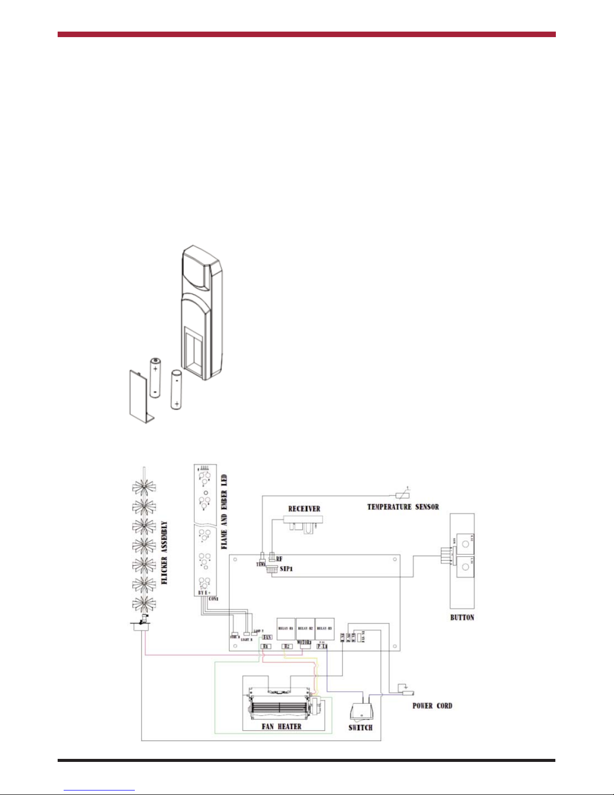
BATTERY REPLACEMENT - REMOTE CONTROL
The Remote Control requires two AAA Batteries
which are fitted by removing the back cover and
inserting the batteries into the housing as shown in
Fig 14.
WIRING DIAGRAM
Page 12

EXPLODED VIEW
12
Waterford Stanley Ltd.,
Unit 401-403, IDA Industrial Estate, Cork Road,
Waterford, Ireland.
Tel: (051) 302300 Fax (051) 302315
N00784AXX Rev: 001
SG 010618
NO DESCRIPTION ARBI100 ARBI130
11 BLOWER & HEATER
ASSEMBLY
602120B
12 FLICKER ASSY 3109503 357503
13 REMOTE CONTROL 101050203
14 LOG SET 10305571 10305533
15 MEDIA HOLD BRACKET 3109017 357107
ADJUSTABLE FOOT 10203015
THERMOSTAT 10114001B
NO DESCRIPTION ARBI100 ARBI130
1 4 SIDED FRAME 3109501 3057501
2 FRONT GLASS 10701187 10701165
3 BACK GLASS 10701168 10701186
4 BOTTOM GLASS 10702158B 10702159B
5 LED STRIP FOR TRAY 601136B
6 LED STRIP FOR FLAME 601136B
7 FLAME MOTOR 10101201C
8 CONTROL PANEL 601035
9 POWER SWITCH 10104010
10 MAIN PCB 601094F
 Loading...