

Page 1
06/10 EINS 514810
REMEMBER, when replacing a part on this appliance, use only spare parts that you can be assured conform to the safety
and performance specification that we require. Do not use reconditioned or copy parts that have not been clearly
authorised by Waterford Stanley.
PLEASE READ THESE INSTRUCTIONS BEFORE SERVICING THIS APPLIANCE
Alpha
120/150K
Servicing Instructions
Page 2

Contents
SECTION CONTENTS PAGE
CONSUMER PROTECTION 3
HEALTH & SAFETY 3
INTRODUCTION 4
SERVICE SCHEDULE 4
BURNER REMOVAL PREPARATION 5
BURNER ACCESS 5
BURNER REMOVAL 6
BURNER HEAD REMOVAL 6
CLEANING HEAT EXCHANGER CLEANING 7
HOTPLATE REMOVAL 8
OVEN & HOTPLATE FLUEWAY CLEANING 8
BURNER SERVICING INTRODUCTION 9
BURNER NOZZLE REMOVAL 10
BURNER NOZZLE REPLACEMENT 10
PHOTO ELECTRIC CELL (PEC) CLEANING 11
FAN CLEANING 11
RE-ASSEMBLE BURNER 11
OIL PUMP SERVICING INTRODUCTION 12
OIL PUMP STRAINER CLEANING 12
OIL LINE FILTER CLEANING 12
RE-COMMISSIONING BLEED AIR FROM OIL SUPPLY 13
FIT PRESSURE GAUGE 13
SWITCH ON ELECTRICITY 13
VENT OIL PUMP 13
ADJUST OIL PRESSURE 13
SET COMBUSTION AIR 14
CHECK SMOKE 14
REPLACEMENT OF FAN MOTOR 15
PARTS (BURNER) CHECK SMOKE 15
IGNITOR 16
RELAY 16
SOLENOID COIL 16
CONTROL BOX 17
PEC 17
PUMP ACCESS 17
REPLACEMENT OF ELECTRICAL COMPONENT ACCESS 18-19
PARTS (ELECTRICAL TO FIT NEW BOILER CONTROL THERMOSTAT 20
CONTROLS) TO FIT NEW BOILER PUMP OVERRUN THERMOSTAT 20
TO FIT NEW COOKER SAFETY OVERHEAT 21
THERMOSTAT
TO FIT NEW BOILER SAFETY OVERHEAT THERMOSTAT 21
TO FIT NEW OVEN CONTROL THERMOSTAT 22
TO FIT NEW SELECTOR SWITCH 22
RE-ASSEMBLE 23
ELECTRICAL CONTROLS PUMP OVERRUN FACILITY 24
OVERHEAT SAFETY THERMOSTATS 24
TERMINAL STRIP CONNECTIONS 25
FAULT-FINDING APPLIANCE WIRING DIAGRAM 26
BURNER DOES NOT START 27-29
FAULT FINDING (BOILER) 30-31
FAULT FINDING (COOKER) 32-33
HIGH SMOKE NUMBERS/OIL SMELLS 34
2
Page 3

Consumer Protection
As responsible manufacturers we take care to make sure that our products are designed and
constructed to meet the required safety standards when properly installed and used.
IMPORTANT NOTICE: PLEASE READ THE ACCOMPANYING WARRANTY.
Any alteration that is not approved by Waterford Stanley could invalidate the approval of the
appliance, operation of the warranty and could affect your statutory rights.
Health & Safety
This appliance may contain some of the materials that are indicated. It is the Users/Installers
responsibility to ensure that the necessary protective clothing is worn when handling where
applicable, the pertinent parts that contain any of the listed materials that could be interpreted as
being injurious to health and safety, see below for information.
Firebricks, Fuel beds, Artificial Fuels
When handling use disposable gloves.
Fire cement
When handling use disposable gloves.
Glues and Sealants
Exercise caution - if these are still in liquid form use face mask and disposable gloves.
Glass Yarn, Mineral Wool, Insulation Pads, Insulation Fibre
May be harmful if inhaled. May be irritating to skin, eyes, nose and throat. When handling avoid
contact with skin or eyes. Use disposable gloves, face-masks and eye protection. After handling
wash hands and other exposed parts. When disposing of the product, reduce dust with water
spray, ensure that parts are securely wrapped.
Kerosene and Gas Oil fuels (mineral oils)
1. The effect of mineral oils on the skin vary according to the duration of exposure.
2. The lighter fractions also remove the protective grease normally present on the surface of
the skin. This renders the skin dry, liable to crack and more prone to damage caused by cuts
and abrasions.
3. ‘Oil acne’ is recognised by the presence of skin rashes. The arms are most often affected,
but may occur where there is contact with oil or oil clothing.
- Seek medical attention for any rash.
- Avoid skin contact with mineral oil or clothing containing mineral oil.
4. Inhalation of mineral oil vapours must be avoided. Never fire the burner in the open air as
unburnt oil vapours are likely to occur.
5. Use a suitable barrier cream which will give protection against mineral oil, lanolin based hand
cream are usually very effective.
6. Never syphon minerals oil by mouth. If accidentally swallowed, call a doctor, do not induce
vomiting.
NOTE: SMOKE/SMELL EMITTED DURING INITIAL USAGE
Some parts of the cooker have been coated with a light covering of protective oil. During initial
operation of the cooker, this may cause smoke/smell to be emitted and is normal and not a fault
with the appliance, it is therefore advisable to open doors and or windows to allow for ventilation.
Lift the lids to prevent staining the linings.
3
Page 4

To ensure the best performance from your Stanley Alpha
it should be serviced once a year; preferably at the start
of the heating season.
This appliance must be commissioned by an approved
engineer.
Failure to install and maintain the appliance correctly
could lead to prosecution.
An additional flueway and combustion chamber clean
halfway through the heating season may be necessary in
some cases.
The Stanley Alpha cannot be serviced whilst hot, so both
oven and boiler thermostats should be turned off on the
evening before the service visit.
Annual Service
During annual service burner nozzles and burner head
seals MUST BE CHANGED. Flexible oil lines must be
changed every 2 years.
WIRING: Ensure there is no damage or loose
connections. This should be carried out by a competent
engineer.
BURNER REMOVAL - for cleaning and inspection.
CLEANING - Boiler heat exchanger, flueways, oven and
hotplate flueways together with insulation fibre burner
chambers.
BURNER SERVICING.
OIL PUMP SERVICING - Cleaning of fuel line strainer.
RE-COMMISSIONING
REPLACEMENT PARTS
Oven Door Fit - Both doors must be checked and adjusted
if necessary to ensure the alignment with the door catch
is correct, the keep is secure and the oven is sealed when
the door is closed.
Additional Flueway Clean
It may be necessary in some installations to give the
boiler flueways a clean out at the end of the heating
season.
4
INTRODUCTION SERVICE SCHEDULE
Page 5
WARNING: BEFORE REMOVING SERVICE ACCESS
COVERS OR THE OIL BURNERS ENSURE THAT ALL
ELECTRICAL SUPPLIES TO THE APPLIANCE HAVE
BEEN ISOLATED.
The burners can be removed without disconnecting the oil
supply pipe. However if the filters are being cleaned or a
pressure gauge fitted to the pump then the oil supply
should be turned OFF and arrangements made to catch
any oil which will leak from the oil pump.
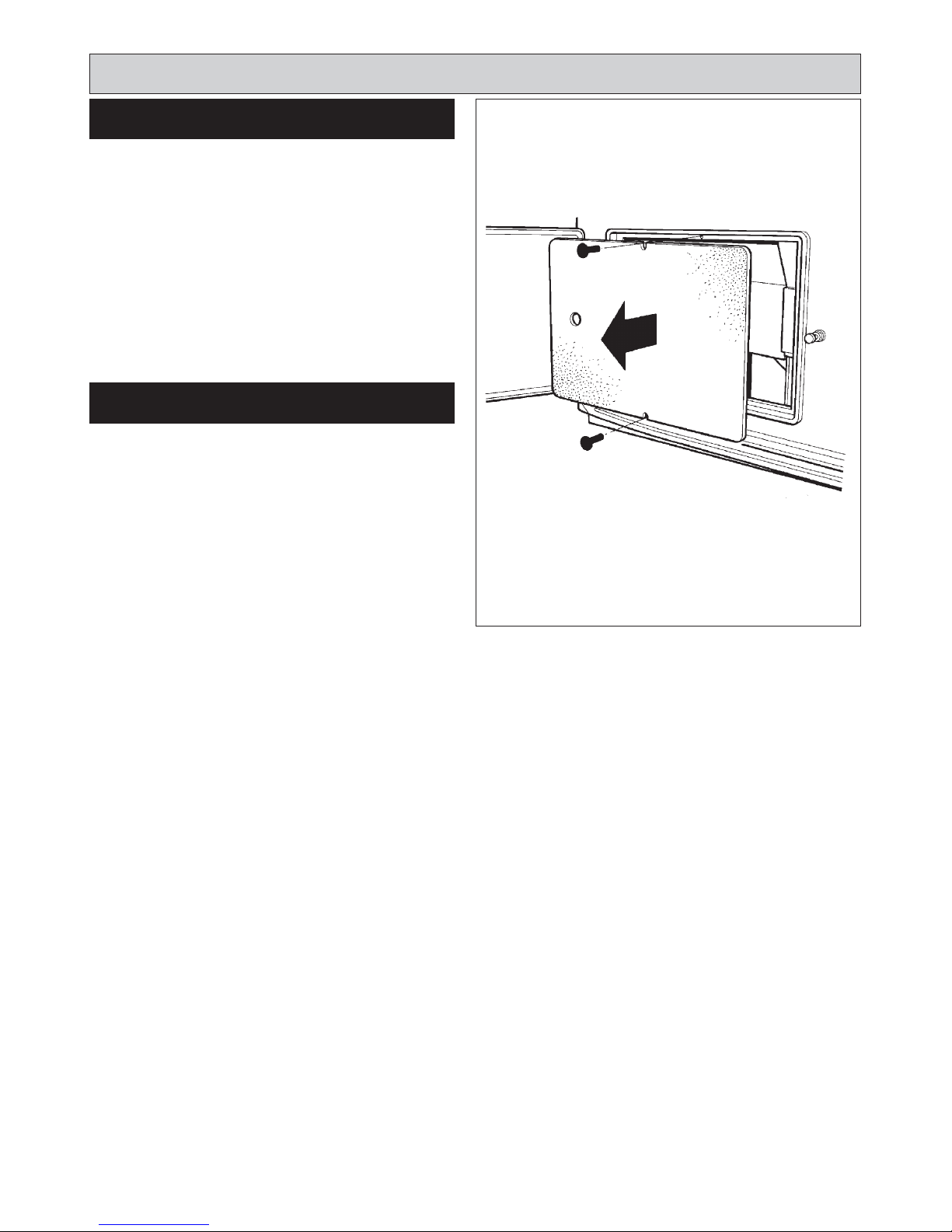
SEE FIG. 1
1. Open up the bottom burner access door. Remove
door and put in a safe place.
2. Remove 2 inner panel securing screws and remove
panel.
5
PREPARATION
BURNER ACCESS
Burner Removal
FIG. 1 DESN 514813
Page 6
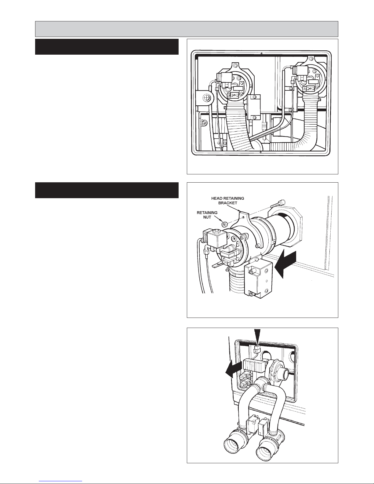
IMPORTANT: DURING BURNER REMOVAL CARE
MUST BE TAKEN NOT TO DAMAGE THE INSULATION
BOARDS.
SEE FIGS. 2, 3 & 4
1. Undo the burner locking nut and remove head
retaining bar.
2. Withdraw burner head.
SEE FIG. 3
3. Place a sheet on the floor in front of the cooker to act
as a working area.
4. Disconnect the 12-pin plug from above the burner.
5. Disconnect air intake.
SEE FIG. 4
6. Slacken 2 M6 fixings and remove flue safety
thermostat.
7. Withdraw burner unit.
6
BURNER REMOVAL
FIG. 2
FIG. 3
FIG. 4
DESN 514814
DESN 514847
DESN 514815
Burner Removal
BURNER HEAD REMOVAL
Page 7
IMPORTANT: DURING CLEANING CARE MUST BE
TAKEN NOT TO DAMAGE THE INSULATING
BOARDS.
Boiler access is made by opening the top left hand control
door.
1. Remove two cooker control knobs.
2. Remove 2 retaining screws and lift the control panel
free of the aperture.
3. Remove 2 retaining nuts and withdraw burner access
panel.
4. The baffles are assembled in two stacks, it maybe
necessary to slightly lift the top stack of baffles and
withdraw bottom baffle stack first, then withdraw the
second stack of baffles.
Each heat exchanger has 3 rows of baffles.
5. Ensure baffles and flueways are clear of debris and refit baffle stacks as illustrated in Fig 8.
NOTE: One baffle configuration for all three models.
6. Carefully vacuum any debris that has fallen into the
burner chamber.
7. Re-assemble in reverse order.
7
HEAT EXCHANGER CLEANING
Cleaning
FIG. 5
FIG. 7
DESN 514816
DESN 514818
FIG. 6 DESN 514850
FIG. 8 DESN 514819
Page 8
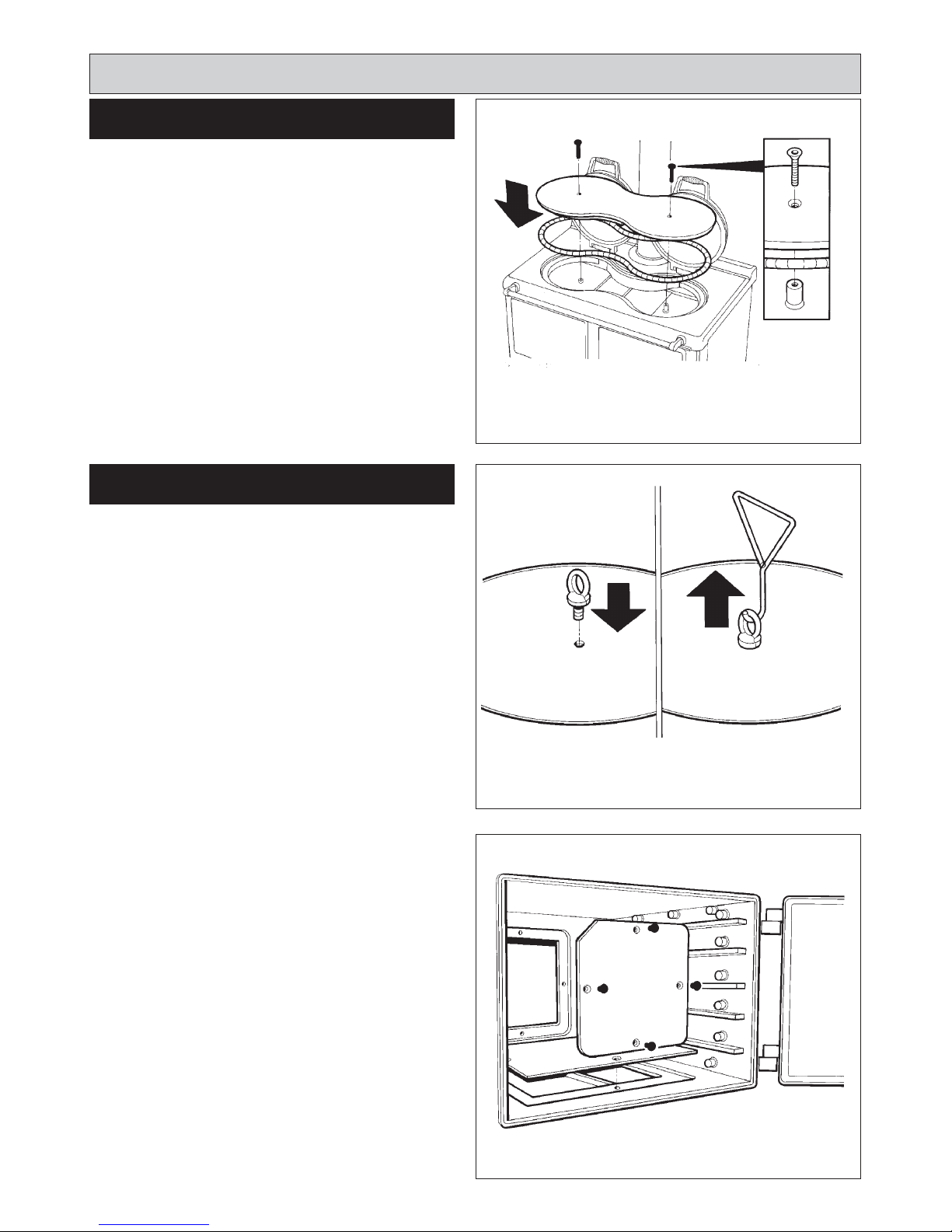
1. Lift up two insulating lids on the top of the cooker.
2. Using a 7mm allen key, unscrew 2 countersunk
retaining bolts. (See Fig. 9).
3. Insert M12 eye hooks into hotplate. (See Fig. 10).
4. Using lifting hooks, lift hotplate vertically and withdraw.
5. Re-assemble in reverse order, noting that it is
recommended to coat the countersunk bolts with antiseize compound prior to fitting.
SEE FIG. 11
1. Remove the top oven door and place in a safe
position.
2. Remove rear and base access doors use hex. driver.
3. Thoroughly clean top, side and base flueways through
access apertures with brush.
4. Remove all debris with vacuum cleaner.
5. Replace rear and base access doors. Secure in
position using hex. driver.
6. Brush and clean in between hotplate ribs on
underside.
7. Examine soft rope seal located around hotplate
aperture in top plate and rope seal on hotspot.
Replace if frayed or damaged.
8. Replace hotplate ensuring the underside ribs lie over
the boiler and that it seals to the top plate.
8
Cleaning
FIG. 11 DESN 514820
OVEN & HOTPLATE FLUEWAY
CLEANING
HOTPLATE REMOVAL
FIG. 9
FIG.10
DESN 514841
DESN 514858
Page 9
9
Burner Servicing
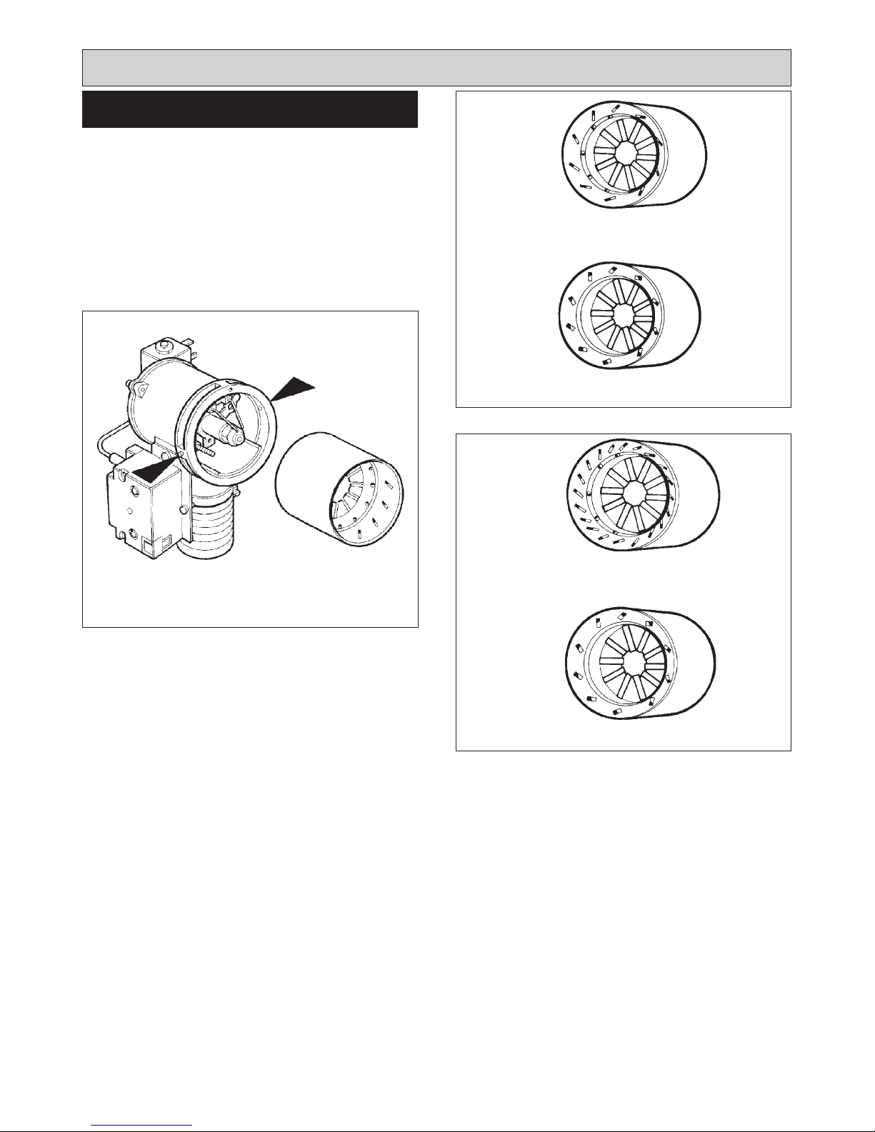
SEE FIG 12, 13A & 13B
It is recommended that each side of the burner is serviced
individually so as not to get the components from the two
burners mixed up.
The correct combination of burner blast tubes are shown.
To remove blast tube, slacken two grub screws, pull
forward.
120K
150K
INTRODUCTION
FIG. 12
FIG. 13B
FIG. 13A
DESN 512005
COOKER 10
VANES
COOKER 10
VANES
BOILER 10 VANES
5mm HOLES
10 LARGE SLOTS
BOILER 10 VANES
5mm HOLES
20 LARGE SLOTS
Page 10

SEE FIG. 14
1. Disconnect ignition leads.
2. Remove two socket head screws.
3. Remove head assembly complete.
4. Remove ignitor assembly, by removing countersunk
screw and clamp.
5. Unscrew nozzle from its holder with a correctly fitting
tubular spanner to avoid damage to hexagon.
Follow instructions in BURNER ACCESS, Steps 1 to 2, and
BURNER NOZZLE REMOVAL, Steps 1 to 5.
SEE FIG. 14
1. Disconnect ignition leads.
2. Remove 2 socket head screws.
3. Remove head assembly complete.
4. Remove ignitor assembly by removing countersunk
screw and clamp.
5. Fit new ignition electrode assembly, re-assemble in
reverse order.
6. Check electrode gap and re-set if necessary.
SEE FIG. 15
1. Replace nozzle by a new one of the same make and
specification.
2. Ensure that mating faces are clean.
3. Hold nozzle holder with correct spanner when
tightening nozzle.
4. Typically finger tight plus 1/4 turn with spanner is
sufficient.
DO NOT OVERTIGHTEN.
5. Ensure electrode gaps are correct.
10
Burner Servicing
BURNER NOZZLE REMOVAL
BURNER NOZZLE REPLACEMENT
FIG. 14 DESN 514823
3mm
FIG. 15 DESN 510538
IGNITOR REMOVAL
Page 11
SEE FIG. 16
Withdraw Photo Electric Cell from the burner head. Clean
PEC sensing end with a soft cloth taking care not to
scratch the light sensitive body. Re-insert PEC taking care
to insert the correct way round.
Should the cell show signs of distortion or cracking,
replacement will be necessary. See ‘PEC Replacement’ Page 17.
SEE FIG. 17
1. Remove pozi screws, pull off fan case inlet.
2. Clean between the blades of the fan impellor with a
small brush and remove any residue.
Re-assemble the burner in reverse order.
NOTE: Burner head gaskets should be renewed at each
service.
11
Burner Servicing
PHOTO ELECTRIC CELL (PEC)
CLEANING
FIG. 17 DESN 514824
FIG. 16 DESN 514848
FAN CLEANING
RE-ASSEMBLE BURNER
Page 12

SEE FIG. 14
To carry out servicing on the oil pump. Turn off the oil line
isolating valve near to the appliance.
SEE FIG. 18
1. Remove 4 socket head screws
2. Remove filter.
3. Wash with clean petrol or paraffin.
4. Re-assemble in reverse order.
1. Turn OFF the line isolating valve fitted prior to the oil
line filter.
2. Follow manufacturers instructions to remove filter
element from the housing, taking care to collect
kerosene residue from the filter housing.
3. Wash filter thoroughly in clean petrol or paraffin.
4. Re-assemble in reverse order.
NOTE: Flexible fuel hose (s) must be replaced every 2
years.
INTRODUCTION
Oil Pump Servicing
12
FIG. 18 DESN 512002
OIL PUMP STRAINER CLEANING
COVER
STRAINER
SEAL
FUEL INLET
OIL LINE FILTER CLEANING
Page 13

SEE FIG. 20
Disconnect the flexible oil pipe line at the pump inlet, open
the stop valve slowly and run off some of the oil into a
receptacle to establish an air free supply to the pump.
Remake the connection oil tight and leave valve open.
SEE FIG. 19
Remove the bleed screw from the manifold and fit an oil
pressure gauge with R 1/8 connection to check the pump
output pressure.
Set the boiler burner time clock to continuous and turn the
boiler thermostat to maximum. The boiler burner should
run on pre-purge for 7-15 seconds. With the ignition spark
energised. The oil solenoid valve should open allowing
the burner to fire.
Until all the air from the oil pump is flushed out there may
be some flame instability resulting in the burner locking
out. This will be shown by the burner stopping and the
reset button will be illuminated in the control box. IN THIS
EVENT, WAIT AT LEAST ONE MINUTE, then press the
reset button to restart. (See Fig. 21).
SEE FIG. 19
Whilst the burner is running, vent air from the pump by
slackening the pressure gauge port sufficient to allow air
to bleed out. When bubble free oil seeps out re-tighten.
SEE FIG. 20
With the burner running check the oil pressure on the
pressure gauge.
If the pressure gauge is not indicating the correct reading
then adjust the pressure by turning the pressure regulator
clockwise to increase or anti-clockwise to decrease the
pressure until the pressure gauge reads 10 bar
(145Ibf/In
2
).
13
BLEED AIR FROM OIL SUPPLY
SWITCH ON ELECTRICITY
VENT OIL PUMP
Re-commissioning
FIT PRESSURE GAUGE
FIG. 19
FIG. 20
DESN 514825
DESN 511997
OIL
PRESSURE
ADJUSTMENT
ADJUST OIL PRESSURE
FIG. 21 DESN 514807
Page 14

SEE FIG. 22
After 15 minutes of the boiler burner running.
Remove the collar infill trim and lift up the enamelled flue
collar. Support the flue collar above the cooker.
NOTE: The LH sampling screw is for the boiler and the
RH sampling screw is for the cooker.
Remove the plugging screw and insert the sensing end of
a portable indicator to check the CO
2 (Carbon Dioxide)
level. Adjust the boiler burner air intake until a reading of
11.0/11.5% is recorded on the indicator.
SEE FIG. 23
Remove the CO
2 sampling tube and using the same hole
for flue sampling, insert the sensing end of a Baccarach
Smoke Pump and check that the smoke in the boiler
flueways does not exceed No. 2 on the scale.
Replace the plugging screw.
Switch off the boiler burner.
COOKER BURNER - SEE FIG. 23
Switch on cooker burner.
After 15 minutes of the cooker burner running.
Repeat the above procedures for the cooker burner. To
sample the flue gases from the cooker burner, remove the
RH plugging screw and insert sensing end of a portable
indicator to check CO
2 level. The cooker burner should be
set to 11.0/11.5% maximum Smoke No. 2.
Replace the plugging screw on completion.
14
SET COMBUSTION AIR
Re-commissioning
FIG. 22
FIG. 23
DESN 514826
DESN 514823 A
CHECK SMOKE
Page 15

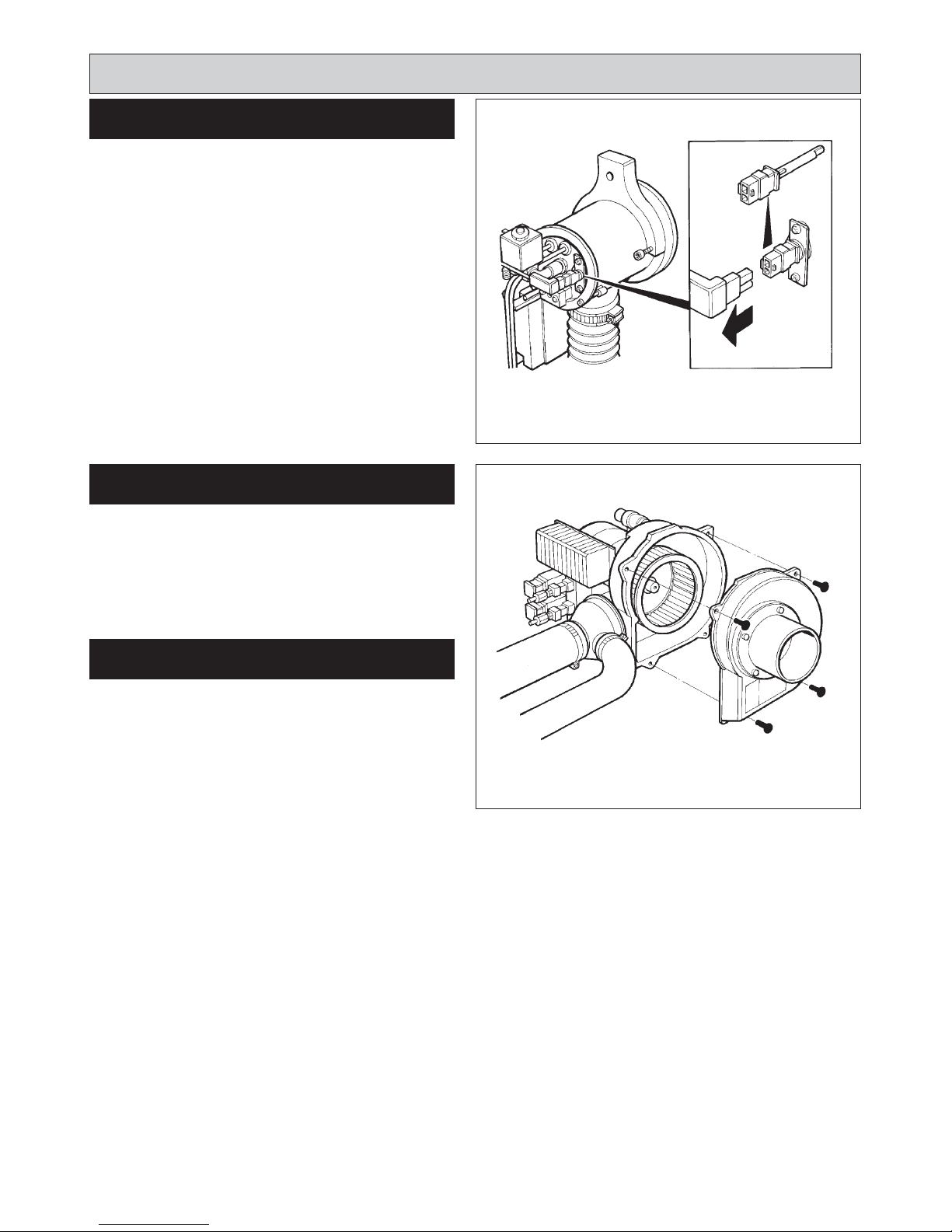
SEE FIG. 24
1. Remove 3-pin plug.
2. Disconnect oil pipe.
3. Remove 4 pozi drive screws, remove fan case inlet.
4. Undo grub screw, remove fan.
5. Remove 4 fixings, withdraw motor.
6. Re-assemble in reverse order.
NOTE: Ensure that gaskets and seals are in place and in
good condition.
15
FAN MOTOR
Replacement of parts (Burner)
FIG. 24 DESN 514828
Page 16

SEE FIG. 25
Follow instructions in sections BURNER ACCESS, Steps
1 to 2, BURNER REMOVAL, Step 4.
1. Remove both HT leads from ignitor.
2. Remove mains plug from ignitor.
3. Remove earth screw.
4. Remove 2 ignitor securing screws.
5. Remove ignitor.
6. Fit new ignitor, re-assemble in reverse order.
1. Open and remove top left hand control door, remove 2
retaining screws and cooker control knobs.
2. Lift and withdraw control panel and turn over.
3. Remove push-on connectors (noting position of each
connector).
4. Remove 2 relay fixing screws.
5. Fit new relay.
6. Re-assemble in reverse order.
SEE FIG. 27
Follow instructions in sections BURNER ACCESS, Steps
1 to 2, BURNER REMOVAL, Steps 1 to 5.
1. Slacken solenoid plug securing screw.
2. Remove plug.
3. Remove solenoid securing nut and washer.
4. Remove solenoid coil.
5. Fit new solenoid coil, re-assemble in reverse order.
16
IGNITOR PACK
FIG. 25
FIG. 26
DESN 514849
DESN 511991
FIG. 27 DESN 514829
RELAY
Replacement of parts (Burner)
SOLENOID COIL
Page 17

SEE FIG. 28
Follow instructions in section ELECTRICAL
COMPONENT ACCESS, Steps 1 to 4.
1. Undo centre fixing screw.
2. Gently pull control box away from base.
3. Fit new control box and re-assemble in reverse order.
SEE FIG. 29
Follow instructions in BURNER ACCESS, Steps 1 to 2.
1. Withdraw PEC from burner head.
2. Push in retaining clip and slide PEC out.
3. Fit new PEC.
4. Re-insert PEC taking care to insert the correct way
round.
SEE FIG. 30
Follow instructions in section BURNER ACCESS, Steps 1
to 2 and BURNER REMOVAL, Steps 1 to 5.
1. Isolate fuel supply.
2. Disconnect flexible hose. (This must be replaced every
2 years.
3. Remove solenoid plug.
4. Remove feed pipe.
5. Slacken three securing screws and remove pump.
6. Check drive, replace if worn or damaged.
7. Replace pump, re-assemble in reverse order.
17
Replacement of parts
(Burner)
FIG. 28 DESN 511992
FIG. 29 DESN 514848
CONTROL BOX
PEC
FIG. 30
DESN 511995
PUMP ACCESS
Page 18

BEFORE REMOVING SERVICE ACCESS COVERS
ENSURE THAT ALL ELECTRICAL ACCESS TO THE
APPLIANCE HAS BEEN SWITCHED OFF (SWITCH
OFF AND REMOVE PLUG.
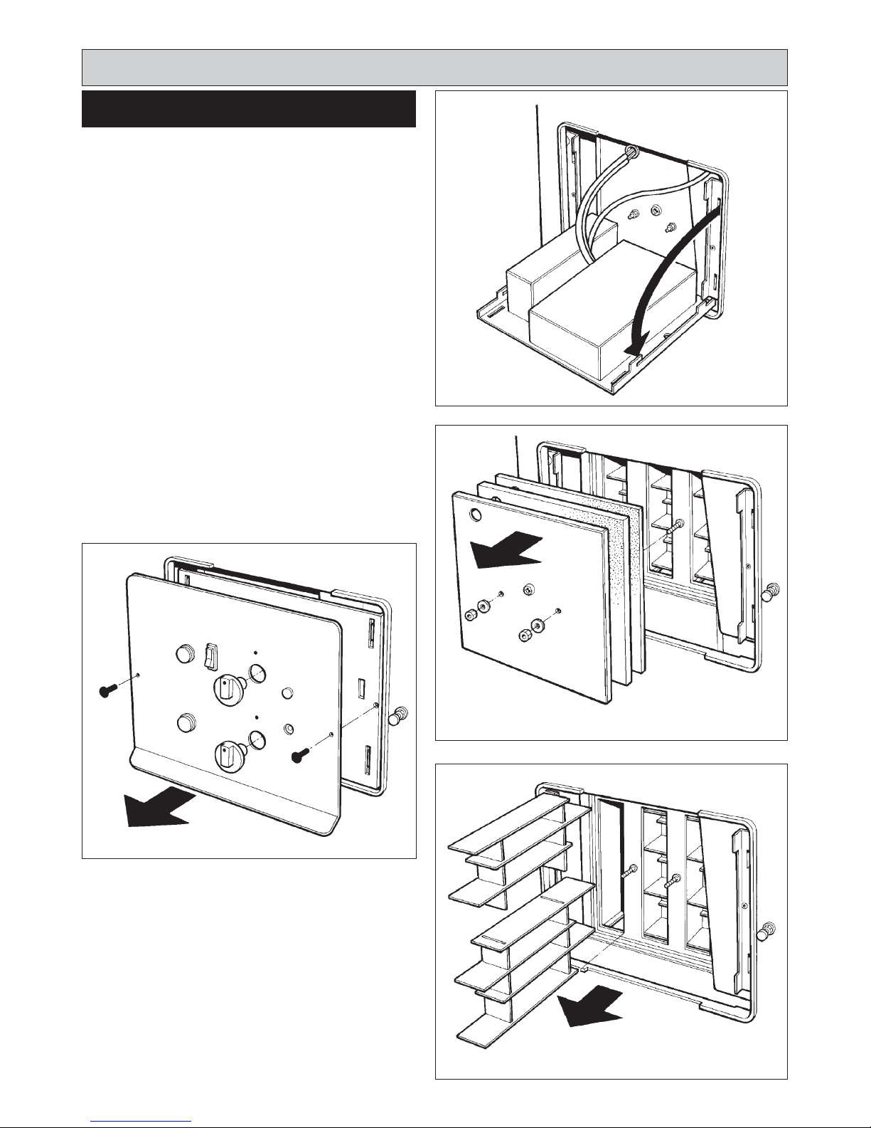
SEE FIG.31 & 32
1. Remove the controls door and place in a safe position.
2. Remove both thermostat control knobs.
3. Remove the 2 cover panel fixing screws.
4. Disconnect cover panel. It will be necessary to
disconnect the push-on tags from the selector switch
and cooker ‘ON’ neon.
SEE FIG. 33
5. Lift control panel chassis and withdraw from aperture.
6. To fully access the rear of the control chassis, the
thermostat capillaries should be removed from their
pocket.
18
ELECTRICAL COMPONENT
ACCESS
Replacement of parts
(Electrical controls)
FIG. 31 DESN 514816
FIG. 33 DESN 514830
FIG. 32 DESN 514850
Page 19

Replacement of parts
(Electrical controls)
FIG. 34 DESN 514830
19
Page 20

SEE FIG. 35
Follow instructions in section ELECTRICAL
COMPONENT ACCESS, Steps 1 to 6.
1. Undo the two screws on the front of the chassis which
hold the thermostat in place.
2. Remove the two push-on connectors from back of
thermostat.
3. Replace thermostat. Take care to push thermostat
phial correctly into the pocket provided. The
thermostat should be mounted with tag P at the right
hand side.
4. Re-connect push on connector wires. The GREY wire
to 1 and WHITE wire to P.
To complete, follow instructions in RE-ASSEMBLE, Steps
1 to 6.
SEE FIG. 36
Follow instructions in section ELECTRICAL
COMPONENT ACCESS, Steps 1 to 6.
1. Undo the two screws on the front of the chassis which
hold the thermostat in place.
2. Remove the three push on connectors from back of
thermostat.
3. Replace thermostat. The thermostat should be
mounted with tag P at the left hand side. Take care to
push on thermostat phial correctly into the pocket
provided.
4. Re-connect push on connector wires. The GREY wire
from the pump to P, the other BROWN wire to 2 and
the YELLOW to 1.
To complete, follow instructions in section REASSEMBLE, Steps 1 to 6.
Replacement of parts
(Electrical controls)
TO FIT NEW BOILER CONTROL
THERMOSTAT
20
FIG. 35 DESN 514747
TO FIT NEW BOILER PUMP
OVERRUN THERMOSTAT
FIG. 36 DESN 514851
Page 21

SEE FIG. 37
Follow instructions in section ELECTRICAL
COMPONENT ACCESS, Steps 1 to 6.
1. Undo the two screws on the front of the chassis which
holds the thermostat in place.
2. Remove the two push on connectors from the back of
the thermostat. Open oven door to access the
thermostat phial which passes into the oven at top LH
corner.
3. Remove LH side plate, slacken screw where the phial
passes through RH side and rotate. Slacken screw
front phial mounting bracket and rotate.
4. Replace thermostat, thermostat phial should be repositioned in the same position as removed.
To complete follow instructions in section REASSEMBLE, Steps 1 to 6.
SEE FIG. 38
Follow instructions in section ELECTRICAL
COMPONENT ACCESS, Steps 1 to 6.
1. Undo the central hexagon nut on the front of the
chassis which holds the thermostat in place.
2. Remove the push on connectors from back of
thermostat.
3. Replace thermostat. Take care to push thermostat
phial correctly into the pocket provided.
4. Re-connect push on connector wire as Fig. 33.
To complete follow the instructions in section REASSEMBLE, Steps 1 to 6.
Replacement of parts
(Electrical controls)
TO FIT NEW COOKER SAFETY
OVERHEAT THERMOSTAT
21
FIG. 37 DESN 514747
TO FIT NEW BOILER SAFETY
OVERHEAT THERMOSTAT
PINK
RED
FIG. 38 DESN 514852
Page 22

SEE FIG. 39
Follow instructions in section ELECTRICAL
COMPONENT ACCESS, Steps 1 to 6.
1. Undo the two screws on the front of the chassis which
holds the thermostat in place.
2. Remove the two push on connectors from back of
thermostat.
3. Open roasting oven door to access thermostat phial
and capillary which will pass into the oven at the top.
4. Where the phial passes through the roasting oven
side, slacken screw front phial, mounting bracket and
rotate.
5. Replace thermostat. The thermostat should be
mounted with tag P at the right hand side. Reposition
the phial in same position as removed.
6. Re-connect push on connector. The VIOLET to P2,
PINK to P and BLACK to P1.
NOTE: Ensure phials do not make contact with oven
castings.
To complete follow instructions in RE-ASSEMBLE, Steps
1 to 6.
SEE FIG. 40
Follow instructions in section ELECTRICAL
COMPONENT ACCESS, Steps 1 to 4.
1. To remove switch from the cover panel press the two
toggles at top and bottom of switch, push switch
through panel.
2. Push replacement switch into aperture and click into
place. The switch should be fitted with terminal 1 at the
top.
To complete follow the instructions in section REASSEMBLE, Steps 3 to 6.
Replacement of parts
(Electrical controls)
22
TO FIT NEW SELECTOR SWITCH
FIG. 39 DESN 514831
TO FIT NEW OVEN CONTROL
THERMOSTAT
FIG. 40 DESN 510553 A
Page 23

1. Locate thermostat phials into boiler pocket.
2. Locate the base of the control chassis into the bottom
of the doorway aperture, tilt the chassis backwards
into position and secure with the four screws.
3. Thread the two wires for the selector switch through
the aperture and connect them onto the rear of the
selector switch fitted in the outer panel. Connect the
VIOLET and BLUE wires to the COOKER ON neon.
Connect the ORANGE wire on 1 and the PURPLE wire
on 2.
4. Refix the outer panel in position and secure with the 2
screws.
5. Replace the thermostat knobs.
6. Replace the controls door.
Replacement of parts
(Electrical controls)
23
FIG. 41 DESN 514832
RE-ASSEMBLE
Page 24

When the programmer switches OFF the boiler channel
then the water circulating pump will be switched off. If
during the period shortly after this the residual heat in the
appliance causes the water temperature in the boiler to
rise above 65°C then the pump overrun thermostat will
change over. This will switch on the circulating pump.
BOILER
This thermostat is a safety cut-out device which is
intended to operate if the other controls fail. This control
will “lock-out” and switches everything off except for the
programmer clock and the “Pump Overrun” facility.
This thermostat has to be manually reset once the
temperature has cooled down.
COOKER
This thermostat is a safety cut-out device which operates
if the control thermostat fails.
This thermostat automatically resets once the
temperature has cooled down.
Electrical Controls
PUMP OVERRUN FACILITY OVERHEAT SAFETY THERMOSTATS
24
Page 25

25
FIG. 42
Electrical Controls
SW/L COOKER
N/A
SW/L BOILER
N/A
PL - LIVE
PN - NEUTRAL
PL - LIVE
PN - NEUTRAL
L LIVE
N NEUTRAL
E EARTH
COOKER SWITCHED - LIVE
DO NOT USE
DO NOT USE
EXTERNAL PROGRAMMER - LIVE - MUST BE
CONNECTED DIRECTLY TO THIS SUPPLY
EXTERNAL PROGRAMMER - NEUTRAL
PUMP SUPPLY - LIVE (THE CIRCULATING PUMP MUST
BE CONNECTED DIRECTLY TO THIS SUPPLY)
PUMP SUPPLY - NEUTRAL (THE CIRCULATING PUMP
MUST BE CONNECTED DIRECTLY TO THIS SUPPLY)
3 AMP PERMANENT SUPPLY
NOTE:
The 3 channel programmer LIVE must be connected directly to the programmer LIVE supply from the cooker.
TERMINAL STRIP CONNECTIONS
BOILER SWITCHED - LIVE
Page 26

26
FIG. 43
Fault Finding
Page 27

Burners
Check that the burners have not gone to lock-out.
Causes of lock-out can be:-
z No ignition, ignition electrode incorrectly positioned or insulation cracked, spark generator fault.
z No oil supply.
z Poor combustion.
z Photo electric cell incorrectly positioned, cracked or needs cleaning.
z Live and Neutral connections reversed.
z Faulty control box.
z Faulty fire valve.
z Faulty relays.
REFER TO FLOW DIAGRAMS FOR ELIMINATION PROCEDURES.
General
You can carry out some checks on the controls before you need to access the controls compartment behind the control
door.
If only one of the burners is not running then the fault must be after the safety overheat thermostat.
Conversely if both burners are affected then the fault lies before the programmer connections.
For access to individual controls refer to section Replacement Parts and for wiring continuity checks refer to Figs. 37 and
38 for detailed and schematic wiring diagrams.
To check out the electrical wiring at the burners you will first have to access the burner chamber. Use the following
procedure:
1. Isolate the electrical power supply.
2. Open up the bottom burner access door. Remove door and put in a safe place.
3. Unscrew the 2 screws holding the inner panel in place and remove panel.
The external mains connections are made to a terminal block situated in the front left hand corner of the burner chamber.
Re-connect the electrical supply and that there is 230V power supply available across the mains input connection L & N
on the terminal block, if not then check connecting leads, fuses and whether power is available at mains plug.
If power is available across L & N then check to see whether the overheat cut-out switch has cut-out, if it has been reset
by pushing the centre with a small round tool (i.e. a pencil). Check for continuity across the cooker overheat thermostat.
Fault Finding
27
BURNER DOES NOT START
Page 28

Fault Finding
28
Information system
The information system communicates with the outside world using a LED (the used Flash-Code is similar to the Morse
Code). The messages are optically transmitted by flashing appropriately a LED. Using an (optional) additional terminal the
messages can be recorded and displayed in easily readable form.
Programming sequence display
The built-in microprocessor controls not only the programming sequence but the information system too. The individual
phases of the programming sequence are displayed as Flash-Code.
The following messages can be distinguished:-
FIG. 44
Page 29

Fault Finding
Lock-out diagnoses
In case of a failure the LED is permanently illuminated. Every 10 seconds the illumination is interrupted by a flash code
which indicates the cause of the error. Therefore the following sequence is performed which is repeated as long as the
unit is not reset.
Sequence:
Stray Light Monitoring
The stray light check is performed as the end of the pre-purge time for the duration as mentioned in the table of timings.
Low-voltage protection
at 220 / 240V nominal voltage
The mains voltage has to be more than 187V
eff
(94V
eff
) in order to allow the unit to perform a start-up.
The mains voltage is not only monitored in the start-up phase but also permanently during operation. If the voltage drops
below <160V
eff
(80V
eff
) during start-up or run time the control box goes into lock-out mode. If the voltage rises again, the
control box performs automatically a start-up as soon as the mains voltage is >187V
eff
(94V
eff
)
29
Page 30

30
Fault Finding
Page 31

Fault Finding
31
Page 32

32
Fault Finding
Page 33

33
Fault Finding
Page 34

34
Fault Finding
HIGH SMOKE NUMBERS
OIL SMELLS
INCORRECT
COMBUSTION
SETTINGS
RE-ADJUST
TO
INSTALLATION
INSTRUCTIONS
AIR INTAKE
BLOCKED
CHECK AIR
INLET TO
BURNER
NOZZLE FAULT
REPLACE
NOZZLE
FUMES ON
START UP
DOWN
DRAUGHT
CHECK WITH
GAUGE
OIL SOAKED
HEARTH
BURNER
FAULT
OIL LEAKS AT
PIPE FITTINGS
TAKE APART
AND
REMAKE AS
REQUIRED
LEAKS AT
TUBING
CONNECTORS
ENSURE END
OF TUBING
SQUARE
NUMEROUS
LOCK-OUTS
CURE THE
LOCK-OUT
CONDITION
ODOURS
IN
KITCHEN
OIL PRESSURE
INCORRECT
ADJUST TO
RECOMMENDED
SETTINGS
INCORRECT
COMPONENTS
USED ON
COMBUSTION
HEAD
SEE SERVICING
INSTRUCTIONS
INTERNAL
INSULATION
PANELS
INCORRECTLY
POSITIONED
OR
FAULTY
Page 35

35
Page 36

36
For further advice or information contact your
local distributor/stockist
With Waterford Stanley’s policy of continuous
product improvement, the Company reserves the
right to change specifications and make
modifications to the appliance described at any
time.
Supplied by
Waterford Stanley Ltd
Unit 210
IDA Industrial Estate
Cork Road
Waterford
Ireland
Tel: (051) 302300 Fax: (051) 302315
www.waterfordstanley.com
 Loading...