

Page 1
NOTE: Your furniture may have different design features than those shown in the drawing.
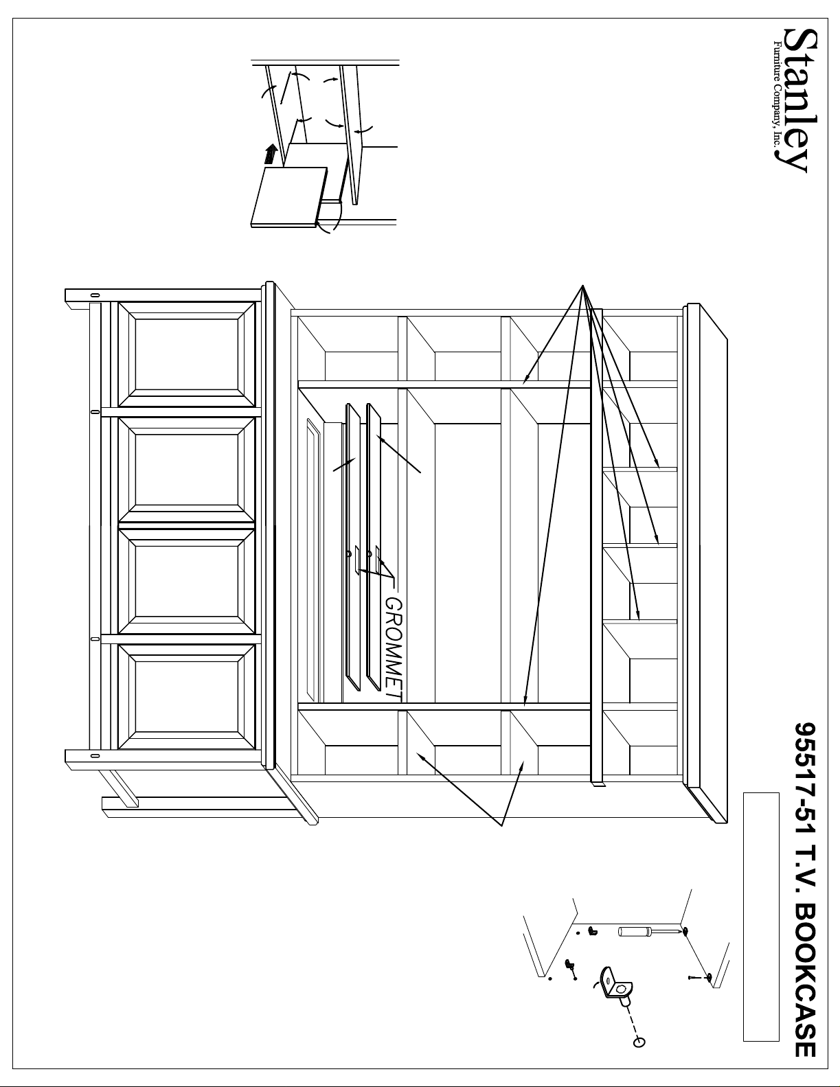
To remove ADJUSTABLE SHELVES,
SUPPORTS, then carefully lift Shelves
CAUTION:
A-1243
Lower Shelves. Align Grooves in the Top
below).
and Lower WIRE SUPPORTS (as shown
slide the PARTITIONS between the Upper
with the WIRE SUPPORTS, and carefully
SUPPORTS
LOWER
SHELF
WIRE
REMOVABLE
PARTITION
GROOVE
UPPER
SHELF
locate WIRE SUPPORTS in the Upper and
and Bottom Edges of the PARTITIONS
To install REMOVABLE PARTITIONS,
REMOVABLE PARTITIONS
INSTRUCTIONS BEFORE
CAREFULLY READ AND
UNDERSTAND ALL
PROCEEDING!
(2) OR MORE PERSONS
-031 LIFT LID
Rest the SHELF on the SHELF
SUPPORTS into Holes as shown.
Replace the lift lid panels by
placing them back into the case.
Run cords thru the grommets
located in the center of the lift lids.
console.
For cord access remove the lift lid
panel from the -51 deck and the
lid from the -31 entertainment
CORD ACCESS
SUPPORTS, and reinstall SCREWS.
-051 LIFT LID
remove SCREWS from SHELF
SHELVES, insert Stem of SHELF
up and out of the Armoire.
To reposition ADJUSTABLE
ADJUSTABLE SHELVES
SCREWDRIVER
RECOMMENDED FOR
ASSEMBLY!
Note: If a Power Screwdriver is used, a
"low torque" setting is recommended!
SCREW
SHELF
SUPPORT
Page 2
NOTE: Your furniture may have different design features than those shown in the drawing.
A-1243-1
CAREFULLY READ AND
2
Self Adhesive
FELT DISCS
-51 T.V. BOOKCASE
-31 ENTERTAINMENT CONSOLE
INSTALLATION!
RECOMMENDED FOR
CAUTION: (2) PERSONS
ASSEMBLY and
1
UNDERSTAND ALL INSTRUCTIONS
Self Adhesive
FELT DISCS
24 7/8"
SCREWS
recommended.
NOTE: If a Power
Screwdriver is used, a
"low torque" setting is
BEFORE PROCEEDING!
UPRIGHTS
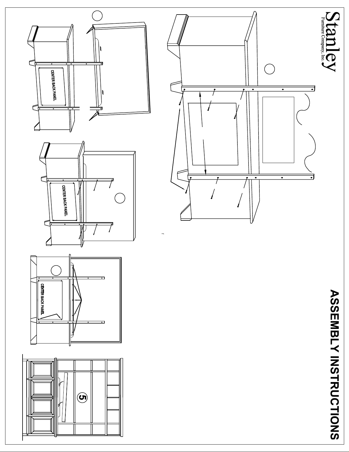
Attaching the PLASMA TV HUTCH to the ENTERTAINMENT CONSOLE
3
Plastic Back Panel Retaining Clips located at the four corners of the Center Back
Panel.
6. Consult with the provider of your Plasma TV for instructions on mounting the
Television Set to the Plasma TV Hutch.
4.
turn the Retaining clips till they lock the Cover rail in place as shown in drawing
the opening of the Entertainment Console Deck. With the Cover Rail in place
5. Optional: To use the Cut-Out Cover Rail to fill the opening in the
clips turned down into
Entertainment Console Deck. Place the Cut-Out Cover Rail with the Retaining
4. For access to TV Receiver wiring and ventilation, the Center Back Panel on
the -31 Entertainment Console may be removed, by loosening the screws on the
Secure the Plasma TV Mounting Panel to the Entertainment Console by
aligned with the Vertical Cleats on the back of the Plasma TV Mounting Panel.
fastening through the Uprights using Screws provided, as indicated in diagram
#3.
Plasma TV Hutch.
3. Lift the Plasma TV Hutch into position on top of the Entertainment Console,
and center it. The Uprights you attached to the Entertainment Console should be
bottom of the Entertainment Console Back Panel.
2. Once the uprights are securely fastened to the Entertainment Console, apply
four Round Self Adhesive Felt Discs [provided] to the Bottom Surface of the
1. Using Screws provided, attach the Wooden Uprights packed with the Plasma
mounted vertically, exactly 24 7/8" apart on center, and should be even with the
TV Hutch to the Back of the Entertainment Console. The uprights should be
4
Retaining Clips
Retaining Clips
 Loading...