

Page 1

ProSet® XT1 Blind Rivet Tool - 76001
Hydro-Pneumatic Power Tool
Service Manual
Original Instruction
Hydro-Pneumatic
Blind Rivet Tool
Page 2
2
ENGLISH
3
2
4 & 5
1
6
7
1n
1l
1k
1j
1i
1h
1g
1f
1e
1d
1a, 1b, 1c
1o
1p
1m
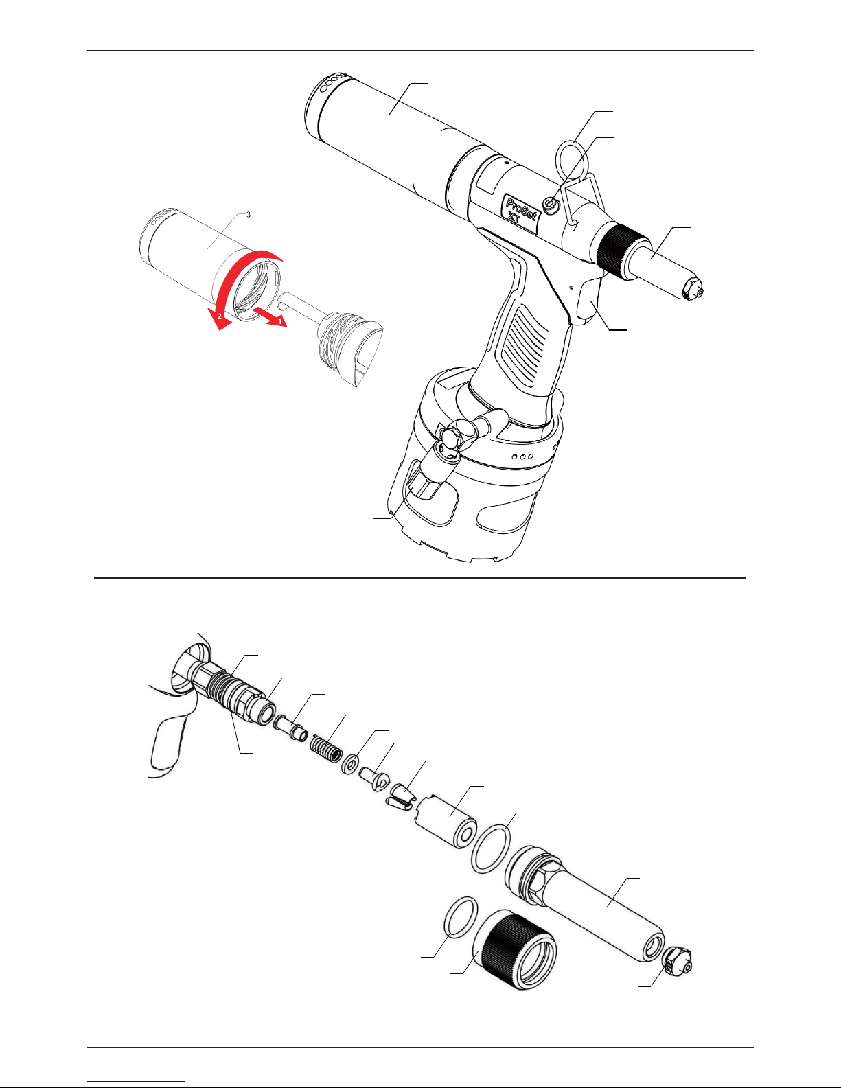
Figure 2
Figure 1
Page 3
3
ENGLISH
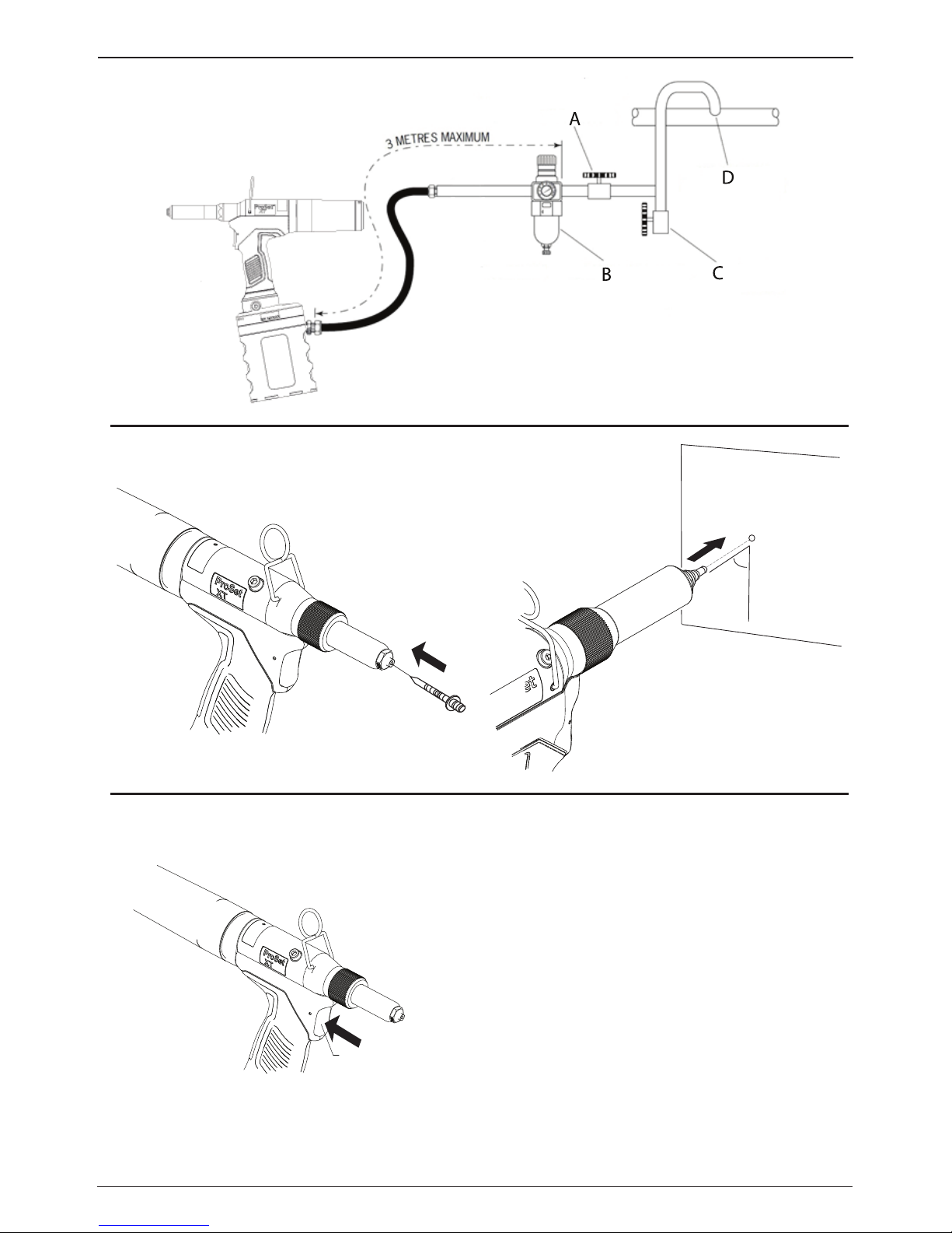
Figure 4
Figure 3
Figure 6
Figure 5
90˚
6
Page 4
4
ENGLISH
Page 5
5
ENGLISH
Page 6

6
ENGLISH
Item Drawing Number Description QTY
Spares
MOQ
Item Drawing Number Description QTY
Spares
MOQ
1a PRN414 NOSE PIECE 1 34 DPN901-022 SPRING 1
1b PRN314 NOSE PIECE 1 35 DPN276-014 MCS VALVE ROD 1
1c PRN514 NOSE PIECE 1 36 DPN900-066 O-RING 2
1d TP144-111 NOSE HOUSING 1 37 DPN900-065 O-RING 2
1e TP144-091 O-RING 1 38 TP144-175 MCS VALVE CASE 1
1f DPN239-006 JAW GUIDE 1 39 TP144-142 MCS VALVE PUSHER 1
1g PRG402-8A JAWS 1set 40 TP144-084 UPPER GASKET 1
1h TP144-117 JAW PUSHER 1 41 TRM00216 HANDLE ASSEMBLY 1
1i TP144-118 URETHANE WASHER 1 42 TRM00249 HANDLE SEALING SKIRT 1
1j TP144-119 JAW PUSHER SPRING 1 43 TP144-085 LOWER GASKET 2
1k TP144-120 MANDREL GUIDE 1 44 TP144-086 UPPER PLATE 1
1l TRM00167 PULLING HEAD 1 45 07005-00088 SCHRADER VALVE 1
1m TP144-113 JAW GUIDE LOCK 1 46 76003-02024 TRIGGER PIN 1
1n TP144-114 JAW GUIDE LOCK SPRING 1 47 07003-00042 O-RING 1
2 TP144-171 SUSPENSION HOOK 1 48 71210-03402 VALVE SPOOL MOULDED 1
3 TRM00227 COLLECTOR BOTTLE ASSEMBLY 1 49 07003-00268 O-RING 1
4 07001-00405 BLEED SCREW 1 50 DPN239-089 PLUG 1
5 07003-00194 BONDED SEAL 1 51 DPN900-045 O-RING 1
6 76003-02008 TRIGGER BUTTON 1 52 TP142-036 HANDLE LOWER 1
7 TRM00221 ON OFF VALVE ASSEMBLY 1 53 76001-02029 POP AVDEL LABEL 1
8 TP144-115 LOCK NUT 1 54 TP144-097 O-RING 1
9 TRM00215 HANDLE UPPER ASSEMBLY 1 55 TP144-078 VALVE SEAT SLEEVE 1
10 76001-02027 PROSET XT1 LABEL 2 56 07003-00281 O-RING 2
11 76001-02028 SAFETY LABEL 1 57 71210-02009 VALVE SEAT 1
12 TP144-159 SCRAPER 1 58 TP144-087 SLEEVE WASH 1
13 TP144-174 O-RING 1 59 TP144-054 SLEEVE LOCK NUT 1
14 TP144-062 ROD SEAL CASE 1 60 TRM00217 SEAL ASSEMBLY 1
15 76002-02021 BEARING TAPE 1 61 TRM00218 AIR PISTON ASSEMBLY 1
16 07003-00515 ROD SEAL 1 61a 71210-03205 GUIDE RING 1
17 07003-00514 PISTON SEAL 1 61b TP144-099 O-RING 1
18 TRM00161 HYDRAULIC PISTON 1 61c TP144-102 MINI Y PACKING 1
19 76002-02026 BEARING TAPE 1 61d TP144-104 R TYPE RETAINING RING 1
20 TP144-154 O-RING 1 61e TP144-083 EXT VALVE SPRING 1
21 07003-00516 O-RING 1 61f TP144-075 EXHAUST VALVE BODY 1
22 TP144-150 EJECTOR BODY 1 61g TP144-103 CR TYPE RETAINING RING 1
23 TP143-123 EJECTOR NOZZLE 1 62 TRM00219 TUBE VALVE ASSEMBLY 1
24 TP144-094 O-RING 2 63 TRM00220 TUBE ASSEMBLY 1
25 TP144-082 RETURN SPRING 1 64 TP144-077 VALVE PLATE 1
26 TP153-112 END CAP 1 65 TP144-108 HEXAGONAL SOCKET HEAD CAP BOLT 2
27 TP154-110 O-RING 1 66 TP144-098 O-RING 1
28 TP153-111 COLLECTOR ADAPTER MOULDING 1 67 TP143-125 CHAMBER 1
29 TRM00250 O-RING 1 68 TP142-110 CHAMBER PROTECTOR 1
30 DPN900-017 O-RING 1 69 TRM00238 NOSE HOUSING NUT 1
31 TP144-063 EJECTOR GUIDE 1 70 DPN900-004 O-RING 1
32 71213-05101 STEM DEFLECTOR 1 71 TP144-178 MANDREL GUIDE ASSEMBLY 1
33 TP144-064 DEFLECTOR RETAINING NUT 1
1
Page 7

7
ENGLISH
©2017 Stanley Black & Decker inc.
All rights reserved.
The information provided may not be reproduced and/or made public in any way and through any means (electronically or
mechanically) without prior explicit and written permission from STANLEY Engineered Fastening. The information provided is
based on the data known at the moment of the introduction of this product. STANLEY Engineered Fastening pursues
apolicy of continuous product improvement and therefore the products may be subject to change. The information provided
is applicable to the product as delivered by STANLEY Engineered Fastening. Therefore, STANLEY Engineered Fastening cannot
be held liable for any damage resulting from deviations from the original specications of the product.
The information available has been composed with the utmost care. However, STANLEY Engineered Fastening will not accept
any liability with respect to any faults in the information nor for the consequences thereof. STANLEY Engineered Fastening
will not accept any liability for damage resulting from activities carried out by third parties. The working names, trade names,
registered trademarks, etc. used by STANLEY Engineered Fastening should not be considered as being free, pursuant to the
legislation with respect to the protection of trade marks.
CONTENT
1. SAFETY DEFINITIONS ................................................................................................................................ 8
2. SPECIFICATIONS ........................................................................................................................................ 9
2.1. TOOL SPECIFICATIONS ..................................................................................................................................................................9
2.2. TOOL DIMENSIONS ....................................................................................................................................................................... 10
2.3 PLACING SPECIFICATIONS ........................................................................................................................................................ 11
2.4 MAIN COMPONENTS LIST ......................................................................................................................................................... 12
2.5 STANDARD NOSE EQUIPMENT ............................................................................................................................................... 12
3. TOOL SET UP.............................................................................................................................................13
3.1 NOSE EQUIPMENT REF. FIG. 2 ............................................................................................................................................... 13
3.2 AIR SUPPLY (Ref. g. 3.) ............................................................................................................................................................... 13
3.3 PRINCIPLE OF OPERATION ........................................................................................................................................................ 14
4. OPERATION PROCEDURE ........................................................................................................................ 14
4.1 TOOL OPERATION REF. FIG. 1, 4, 5, 6 .................................................................................................................................. 14
4.2 EMPTYING THE MANDREL COLLECTOR. REF. FIG. 1 ..................................................................................................... 14
5. SERVICING THE TOOL .............................................................................................................................. 15
5.1 MAINTENANCE FREQUENCY ................................................................................................................................................... 15
5.2 NOSE EQUIPMENT ........................................................................................................................................................................ 15
5.3 DAILY SERVICING .......................................................................................................................................................................... 15
5.4 WEEKLY SERVICING ...................................................................................................................................................................... 15
5.5 SERVICE KIT ..................................................................................................................................................................................... 15
5.6 PRIMING ............................................................................................................................................................................................. 16
6. MAINTENANCE ......................................................................................................................................... 17
6.1 DISMANTLING THE TOOL ............................................................................................................................................................ 17
7. TROUBLESHOOTING GUIDE ...................................................................................................................20
8. GENERAL SAFETY DATA .......................................................................................................................... 21
8.1 HYSPIN
®
VG32 OIL SAFETY DATA .............................................................................................................................................. 21
8.2 MOLY LITHIUM GREASE EP 3753 SAFETY DATA ................................................................................................................. 22
8.3 MOLYKOTE® 55M GREASE SAFETY DATA .............................................................................................................................. 22
8.4 MOLYKOTE® 111 GREASE SAFETY DATA ................................................................................................................................ 23
Page 8

8
ENGLISH
This instruction manual must be read by any person installing or operating this tool with particular
attention to the following safety rules.
1. SAFETY DEFINITIONS
The denitions below describe the level of severity for each signal word. Please read the manual and pay
attention to these symbols.
DANGER: Indicates an imminently hazardous situation which, if not avoided, will result in death or serious
injury.
WARNING: Indicates apotentially hazardous situation which, if not avoided, could result in death or
serious injury.
CAUTION: Indicates apotentially hazardous situation which, if not avoided, may result in minor
ormoderate injury.
CAUTION: Used without the safety alert symbol indicates apotentially hazardous situation which, ifnot
avoided, may result in property damage.
Improper operation or maintenance of this product could result in serious injury and property damage.
Read and understand all warnings and operating instructions before using this equipment. When using
power tools, basic safety precautions must always be followed to reduce the risk of personal injury.
SAVE ALL WARNINGS AND INSTRUCTIONS FOR FUTURE REFERENCE.
WARNING:
• DO NOT use outside the design intent of Placing STANLEY Engineered Fastening Blind Rivets.
• Use only parts, fasteners, and accessories recommended by the manufacturer.
• DO NOT modify the tool in any way. Any modication to the tool is undertaken by the customer and will
be the customer’sentire responsibility and void any applicable warranties.
• Prior to use, check for misalignment or binding of moving parts, breakage of parts, and any other
condition that aects the tool’soperation. If damaged, have the tool serviced before using. Remove any
adjusting key or wrench before use.
• The tool must be maintained in asafe working condition at all times and examined at regular intervals
for damage and function by trained personnel. Any dismantling procedure will be undertaken only by
trained personnel. Do not dismantle this tool without prior reference to the maintenance instructions.
• The operating supply air must not exceed 7 bar (100 PSI).
• Operators and others in work area must wear approved safety glasses with side shields. Always wear
safety glasses and ear protection during operation.
• Dress properly. Do not wear loose clothing or jewellery. Keep your hair, clothing and gloves away from
moving parts. Loose clothes, jewellery or long hair can be caught in moving parts.
• DO NOT operate atool that is directed towards any person(s).
• DO NOT operate tool with the nose casing removed.
• Adopt arm footing or astable position before operating the tool.
• Prior to use, inspect airlines for damage, all connections must be secure. Do not drop heavy objects on
Hoses. Asharp impact may cause internal damage and lead to premature hose failure.
• DO NOT lift the placing tool by the hose. Always use the placing tool handle.
• Vent holes must not become blocked or covered.
• Disconnect the air hose from the tool before performing any maintenance, attempting to adjust, t or
remove anose assembly.
• Keep tool handles dry, clean, and free from oil and grease.
• When carrying the tool from place to place keep hands away from the trigger to avoid inadvertent
activation.
• Never leave operating tool unattended. Disconnect air hose when tool is not in use.
• Adequate clearance is required for the tool operator’shands before proceeding.
• DO NOT abuse the tool by dropping or using it as ahammer.
• Keep dirt and foreign matter out of the hydraulic system of the tool as this will cause the tool to
malfunction.
Page 9

9
ENGLISH
1. Adequate clearance is required for the tool operator’shands before proceeding.
2. Do not abuse the tool by dropping or using it as ahammer.
• Care should be taken to ensure that spent mandrels do not create ahazard.
• The mandrel collector must be emptied when approximately half full.
• DO NOT use the tool without mandrel collector installed.
• DO NOT let air exhaust opening on the mandrel collector face in the direction of the operator or other
persons.
• Contact with hydraulic uid should be avoided. To minimise the possibility of rashes, care should be taken
to wash thoroughly if contact occurs.
• Material Safety Data Sheets data for all hydraulic oils and lubricants is available on request from your tool
supplier.
STANLEY Engineered Fastening policy is one of continuous product development and improvement
and we reserve the right to change the specication of any product without prior notice.
2. SPECIFICATIONS
The ProSet® XT1 are hydro-pneumatic tools designed to place Stanley Engineered Fastening blind rivets at
high speed.
The tools feature avacuum system for rivet retention and trouble free collection of the spent mandrels
regardless of tool orientation.
When coupled to the relevant nose equipment the ProSet® XT1 can be used to place blind rivets in the range
of Ø2.4mm to Ø4.8mm. Refer to the table on page 7 for alist of all rivets that can be placed.
The safety warnings on pages 4 & 5 must be followed at all times.
2.1. TOOL SPECIFICATIONS
XT1
Pull-Force: @5.5 bar 6.5 kN 1461 lbf
Air Supply Pressure: Min. to Max. 5.0 – 7.0 bar 72.5 – 101.5 lbf/in
2
Oil Pressure: Pull @ 5.5 bar 160 bar 2320 lbf/in
2
Stroke: Minimum Piston Stroke 17.8 mm 0.7 in.
Weight: Incl. nose equipment 1.17 kg 2.58 lb
Weight: without nose equipment 1.07 kg 2.36 lb
Free Air Volume: @ 5.5 bar 1.5 ltr 91.5 in
3
Cycle Time: Approximate 0.4 seconds
Noise Level:
Uncertainty noise: k= 3db(A)
77.95 dB(A)
Vibration Level: Uncertainty
vibration: k= 0.1 m/s
2
<2.5 m/s
2
<8.2 ft/s
2
Page 10

10
ENGLISH
2.2. TOOL DIMENSIONS
Dimensions in millimetres.
Page 11

11
ENGLISH
2.3 PLACING SPECIFICATIONS
Rivet Type
2,4
[3/32´´]
3,2
[1/8´´]
4,0
[5/32´´]
4,3 4,8
[3/16´´]
5,0 6,0 7,0
Open End
Closed End
HR
SSD SSHR
(1) (1)
Multi-Grip
TL
Pull-Thru
T-Rivet (Emhart)
(1)
Self-Plugger
Ultra-Grip (UG) (NPR)
Avex®
Stavex®
Avinox®
Avibulb®
LSR/Bulbex®
T-Lok®
Avdel® SR
Interlock®
Monobolt®
(1)
Avseal® (STD)
(1)(2) (1)(2) (1)(2) (1)(2)
Q Rivet
Klamp-Tite BAPK®
Klamp-Tite BAPKTR®
(1)
VGrip
Is applicable for XT1 tool
(1) Non-standard nose piece required
Is only applicable for XT1 tool
(2) Non-standard nose equipment required.
For afull list of compatible nose equipment for each rivet type, together with assembly and maintenance
instructions, please refer to the ProSet Nose Equipment Manual 07900-09412
Page 12

12
ENGLISH
2.4 MAIN COMPONENTS LIST
Refer to gure 1 & 2 and the table below.
Item Part Number Description Qty
1
TRM00360 Standard nose equipment XT1 tool
1
TRM00361 Standard nose equipment XT2 tool
2 TP144-171 Suspension hook 1
3 TRM00227 Mandrel collector 1
4 07001-00405 Oil plug 1
5 07003-00194 Seal 1
6 76003-02008 Trigger 1
7 TRM00221 On/O valve 1
2.5 STANDARD NOSE EQUIPMENT
Refer to gure 2 and the table below.
Item
XT1 tool
Part Number
Description Qty
1a
PRN314 Nose Piece - 2.4mm [3/32”]
1
- Nose Piece - 4.8 mm [3/16”] (tted on XT2)
1b PRN414 Nose Piece - 3.2 mm [1/8”] (tted on XT1) 1
1c PRN514 Nose Piece - 4.0 mm [5/32”] 1
1d TP144-111 Nose housing 1
1e TP144-091 O-ring 1
1f DPN239-006 Jaw guide 1
1g PRG402-8A Jaws 1 Set
1h TP144-117 Jaw pusher 1
1i TP144-118 Urethane washer 1
1j TP144-119 Jaw pusher spring 1
1k TP144-120 Mandrel guide 1
1l TRM00167 Pulling head 1
1m TP144-113 Jaw guide lock 1
1n TP144-114 Jaw guide lock spring 1
1o DPN900-004 O-ring 1
1p TRM00238 Nose Housing Nut 1
For additional nose equipment please refer to the ProSet® Nose Equipment Manual 07900-09412 or visit
www.stanleyengineeredfastening.com/resource-center/document-library
For afull list of tool accessories, please refer to the ProSet Accessories Manual 07900-09413.
Page 13

13
ENGLISH
3. TOOL SET UP
IMPORTANT - READ THE SAFETY WARNINGS ON PAGES 4 & 5 CAREFULLY BEFORE PUTTING INTO SERVICE.
IMPORTANT - THE AIR SUPPLY MUST BE TURNED OFF OR DISCONNECTED BEFORE FITTING OR
REMOVING THE NOSE ASSEMBLY.
3.1 NOSE EQUIPMENT (REF. FIG. 2)
Item numbers in bold refer to the components in gures 1 & 2 and the tables on page 8.
The XT1 tool will be supplied pre-assembled with the nose piece for 3.2mm [1/8”] rivets and nose pieces for
2.4 [3/32´´] and 4.0mm [5/32] rivets are supplied separately.
Mounting the nose piece
• The air supply must be disconnected.
• Select the correct nose piece for the rivet to be installed.
•
Remove the nose housing nut (1p) and nose housing (1d), including nose piece (1a, b or c),
and o-ring (1e) from the tool.
• Remove the nose piece (1a,b,or c) from the nose casing (1d)
• Select the relevant size nose piece and assemble in reverse order.
Removing complete nose equipment.
• The air supply must be disconnected.
• Remove the nose housing nut (1p) and nose housing (1d), including nose piece (1a, b or c), and o-ring
(1e) from the tool.
• Pull back the jaw guide lock (1m) against the spring (1n) and then remove the jaw guide (1f).
• Remove the jaws (1g) from the jaw guide (1f).
• Remove jaw pusher (1h), urethane washer (1i), and Jaw pusher spring (1j), from the pulling head (1l).
Mounting the complete nose equipment
• The air supply must be disconnected
• Any worn or damaged part should be replaced.
• Clean and check wear on jaws (1g).
• Ensure that the jaw pusher (1h) or the jaw pusher spring (1j) are not distorted.
• Lightly coat jaws (1g) with moly lithium grease.
• Drop Jaws (1g) into the jaw guide (1f).
• Insert jaw pusher (1h) and urethane washer (1i) into the pulling head (1l).
• Pull back the jaw guide lock (1m) and screw the jaw guide (1f) fully on to the pulling head (1l).
• Release the jaw guide lock (1m) and then partially unscrew the jaw guide (1f) until the jaw guide lock
(1m) tooth clicks into the next slot on the jaw guide (1f).
• Place nose casing (1d) over the jaw guide (1f) and tighten fully onto the tool.
Nose assemblies should be serviced at weekly intervals. You should hold some stock of all internal
components of the nose assembly and nose tips as they will need regular replacement.
3.2 AIR SUPPLY (Ref. g. 3.)
Components
A. Stop cock (used during maintenance of lter/regular or lubricated units)
B. Pressure regulator and lter (daily drain)
C. Main supply drain point
D. Take o point from main supply
• All tools are operated with compressed air at aminimum pressure of 5.0 bar.
• Pressure regulators and automatic oiling/ltering systems to be used on the main air supply within
3metres of the tool (see g. 3).
• Air supply hoses will have aminimum working eective pressure rating of 150% of the maximum pressure
produced in the system or 10 bar, whichever is the highest.
Page 14

14
ENGLISH
• Air hoses must be oil resistant, have an abrasion resistant exterior and be armoured where operating
conditions may result in hoses being damaged.
• All air hoses MUST have aminimum bore diameter of 6.4 millimetres.
• Check for air leaks. If damaged, hoses and couplings must be replaced by new items.
• If there is no lter on the pressure regulator, bleed the airline to clear it of accumulated dirt or water
before connecting air hose to the tool.
3.3 PRINCIPLE OF OPERATION
CAUTION - CORRECT SUPPLY PRESSURE IS IMPORTANT FOR PROPER FUNCTION OF THE INSTALLATION
TOOL. PERSONAL INJURY OR DAMAGE TO EQUIPMENT MAY OCCUR WITHOUT CORRECT PRESSURES.
THE SUPPLY PRESSURE MUST NOT EXCEED THAT LISTED IN THE PLACING TOOL SPECIFICATION
Item numbers in bold refer to the components in gures 1 & 2 and the tables on page 8.
When the pneumatic hose is connected to the placing tool, the pull and return cycles of the tool are
controlled by depressing and releasing the trigger (6) located in the handle.
• Air supply must be disconnected.
• Connect the appropriate nose equipment as described on page 9.
• Connect the pneumatic hose to the air on/o valve (7).
• Connect the pneumatic hose mains air supply.
• Switch on the mains supply to the tool by sliding the air on/o valve (7) to the up position.
• Air is now be supplied to the tool and the vacuum system is in operation.
• Pull and release the trigger (6) afew times to the full stroke of the tool to check operation. Observe action
of tool. Check for uid and/or air leaks.
4. OPERATION PROCEDURE
4.1 TOOL OPERATION (REF. FIG. 1, 4, 5, 6)
Installing ablind rivet
• Ensure that the mandrel collector (3) is tted.
• Insert rivet mandrel into the nose piece (1a, b or c). The vacuum system will retain the rivet in the nose
piece.
• Position the tool.
• Ensure nose equipment is at right angle (90°) to the work piece.
• Pull and hold trigger (6) until the rivet is fully set in the application.
• When the rivet has been set completely, release the trigger (6). The tool will return to its initial position
automatically. The mandrel is automatically dropped into the mandrel collector (3) by the vacuum system.
• Mandrel collector must be emptied before it is half full.
CAUTION –DO NOT FORCE THE INSERTION OF ARIVET MANDREL OR RIVET BODY. THIS WILL CAUSE
DAMAGE TO THE TOOL AND/OR APPLICATION.
4.2 EMPTYING THE MANDREL COLLECTOR. (REF. FIG. 1)
CAUTION - DO NOT USE THE TOOL WHEN THE MANDREL COLLECTOR IS REMOVED
• he tool is tted with aquick connect/release mandrel collector (3).
• A60˚ rotation removes or replaces the mandrel collector.
• Removing the mandrel collector (3) from the tool automatically turns OFF the vacuum rivet retention and
mandrel extraction system.
• Retting the mandrel collector turns the vacuum system ON.
Page 15

15
ENGLISH
5. SERVICING THE TOOL
5.1 MAINTENANCE FREQUENCY
Regular servicing must be carried out by trained personnel and acomprehensive inspection performed
annually or every 500,000 cycles, whichever is sooner.
DISCONNECT AIR SUPPLY
CAUTION - Never use solvents or other harsh chemicals for cleaning the non-metallic parts of the tool.
These chemicals may weaken the materials used in these parts.
5.2 NOSE EQUIPMENT
Nose assemblies need to be serviced at weekly intervals or every 5,000 cycles. Hold some stock of all internal
components of the nose assembly and nose pieces, they need regular replacement.
• Disconnect the air supply
• Remove the complete nose assembly using the procedure described in section 3.1.
• Inspect all components. Any worn or damaged parts must be replaced by anew part.
• Particularly check wear on the Jaws (1g).
• Clean all parts and apply moly lithium Grease (07992-00020) to jaws (1g) and taper bore of jaw guide (1f).
• Assemble according to tting instructions in section 3.2.
5.3 DAILY SERVICING
• Before use, check the tool, hose and couplings for air leaks and oil leaks. If damaged, remove the tool from
service and replace aected items with new parts.
• If there is no lter on the pressure regulator, bleed the airline to clear it of accumulated dirt or water
before connecting the air hose to the tool. If there is alter, drain it.
• Check that the nose equipment (1) is correct for the rivet to be placed and that it is tted properly.
• Check that the stroke of the tool meets the minimum specication (ref. 2.1).
• The mandrel collector (3) must tted to the tool.
• Check that the air chamber is fully tightened onto the tool body.
5.4 WEEKLY SERVICING
• Check the tool, hose and couplings for air leaks and oil leaks. If damaged, remove the tool from service
and replace aected items with new parts.
5.5 SERVICE KIT
For an easy complete service, Stanley Engineered Fastening oers the various tools below.
Item Part Number Description Item Part Number Description
1 PRL500-47 11 x 13 Double-end wrench 12 07992-00020 Grease - Moly Lithium
2 PSL600CJ-75 12 x 14 Double-end wrench 13 07992-00075 Grease - Molykote 55M
3 EN600-22 17 Single-ended wrench
4 07900-00158 2mm Pin Punch
5 07900-00164 Circlip Pliers
6 07900-00351 3mm Hexagonal Wrench
7 07900-00469 2.5mm Hexagonal Wrench
8 07900-00692 Trigger Valve Extractor
9 07900-00692 Trigger Valve Extractor
10 07900-00700 Priming Pump Assembly
11 07900-00755 Grease - Molykote 111
Page 16

16
ENGLISH
5.6 PRIMING
Priming is necessary after the tool has been dismantled and prior to operating. It may also be necessary to
restore the full stroke after considerable use, if the stroke has been reduced and fasteners are not now being
fully placed by one operation of the trigger.
Oil Details
The recommended oil for priming is Hyspin® VG32 available in 0.5l (part number 07992-00002) or one gallon
containers (part number 07992-00006).
Priming Kit
To enable you to follow the priming procedure below you will need to obtain a priming kit.
Priming Kit 07900-00688
Item Part Number Description
1 07900-00351 3mm Hexagonal Wrench
2 07900-00700 Priming Pump
3 07900-00224 4mm Hexagonal Wrench
Priming Procedure
IMPORTANT - DISCONNECT THE TOOL FROM THE AIR SUPPLY OR SWITCH OFF AT ON/OFF VALVE
ASSEMBLY 7. REMOVE NOSE ASSEMBLY OR SWIVEL HEAD COMPONENTS.
All operations must be carried out on a clean bench, with clean hands in a clean area.
Ensure that the oil is perfectly clean and free from air bubbles.
Care MUST be taken at all times, to ensure that no foreign matter enters the tool, or serious damage may
result.
Before priming, empty the oil from tool as follows.
• Switch OFF air supply at ON/OFF Valve Assembly (7.)
• Remove all nose equipment (1.) Refer to section 3. 1.
• Remove Bleed Screw (4) and Bonded Seal 5.
• Invert tool over suitable container, switch ON air supply at ON/OFF Valve Assembly (7) and actuate tool.
• Residual oil in the tools hydraulic system will empty through bleed screw orice.
CARE SHALL BE TAKEN TO ENSURE THAT THE BLEED HOLE IS NOT DIRECTED TOWARDS THE OPERATOR
OR OTHER PERSONNEL.
• Switch air supply OFF at ON/OFF Valve (7.)
• Screw priming pump (07900-00700) into bleed screw port, utilizing Seal (5.)
• Actuate Priming Pump by pressing down and releasing several times until resistance is evident and the
Head Piston starts to move rearward.
ENSURE PUMP IS KEPT ‘SQUARE’ TO BLEED SCREW PORT DURING PRIMING OPERATION TO PREVENT
BREAKAGE OF BLEED NIPPLE ON PRIMING PUMP.
• Remove the priming pump, surplus oil will expel from bleed screw port.
• Replace the Bleed Screw 4 together with Bonded Seal (5).
• Switch ON air supply at ON/OFF Valve Assembly (7).
• Check that the stroke of the head piston reaches specication. If not repeat above procedure.
• Switch OFF air supply and ret nose equipment. Refer to section 3.1.
• Check that the stroke of the tool meets the minimum specication of 26 mm.
• To check the stroke, measure the distance between the front face of the Jaw Guide (1f) and the front of
Page 17

17
ENGLISH
the Handle Upper (9), BEFORE pressing the trigger and when the trigger is fully actuated. The stroke is
the dierence between the two measurements. If it does not meet the minimum specication, repeat the
Priming Procedure.
6. MAINTENANCE
IMPORTANT
SAFETY WARNINGS APPEAR ON PAGE 7 & 8.
THE EMPLOYER IS RESPONSIBLE FOR ENSURING THAT TOOL MAINTENANCE INSTRUCTIONS
ARE GIVEN TO THE APPROPRIATE PERSONNEL. THE OPERATOR SHOULD NOT BE INVOLVED
IN MAINTENANCE OR REPAIR OF THE TOOL UNLESS PROPERLY TRAINED.
Every 500,000 cycles the tool must be completely dismantled and inspected Components must be replaced
where worn or damaged. All O rings and seals should be replaced with new ones and lubricated with Molykote
55M grease (07992-00075) for pneumatic sealing or Molykote 111 (07900-00755) for hydraulic sealing.
WARNING
The airhose must be disconnected before any servicing or dismantling is attempted unless specically
instructed otherwise.
The dismantling operation must be carried out in clean conditions.
Before proceeding with dismantling, empty the oil from the tool as follows.
Before priming, empty the oil from tool as follows.
(Ref. g. 1)
• Switch OFF air supply at ON/OFF Valve (7.)
• Remove all nose equipment (1.) Refer to section 3. 1.
• Remove Bleed Screw (4)and Seal (5.)
• Invert tool over suitable container, switch ON air supply at ON/OFF Valve (7)and actuate tool.
• Residual oil in the tools hydraulic system will empty through bleed screw orice.
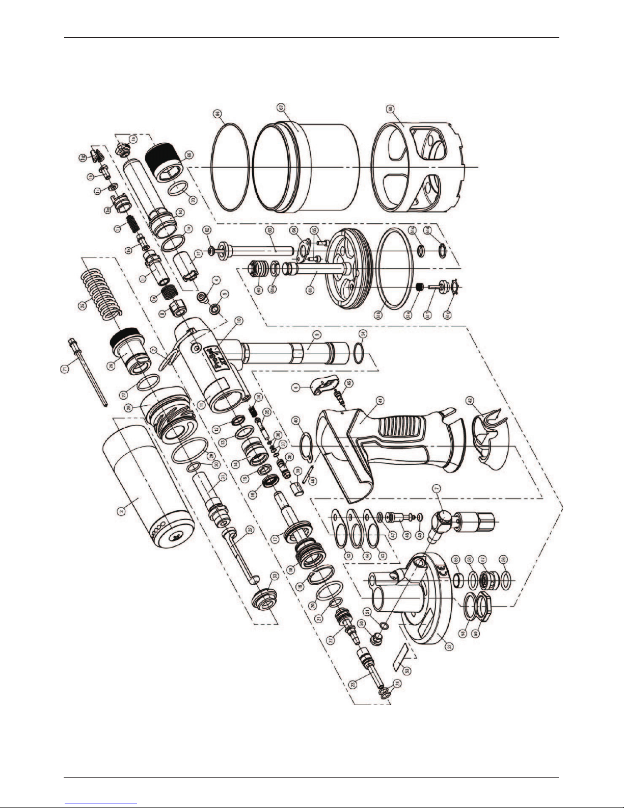
For complete tool servicing we advise that you proceed with dismantling of sub-assemblies in the order
shown below.
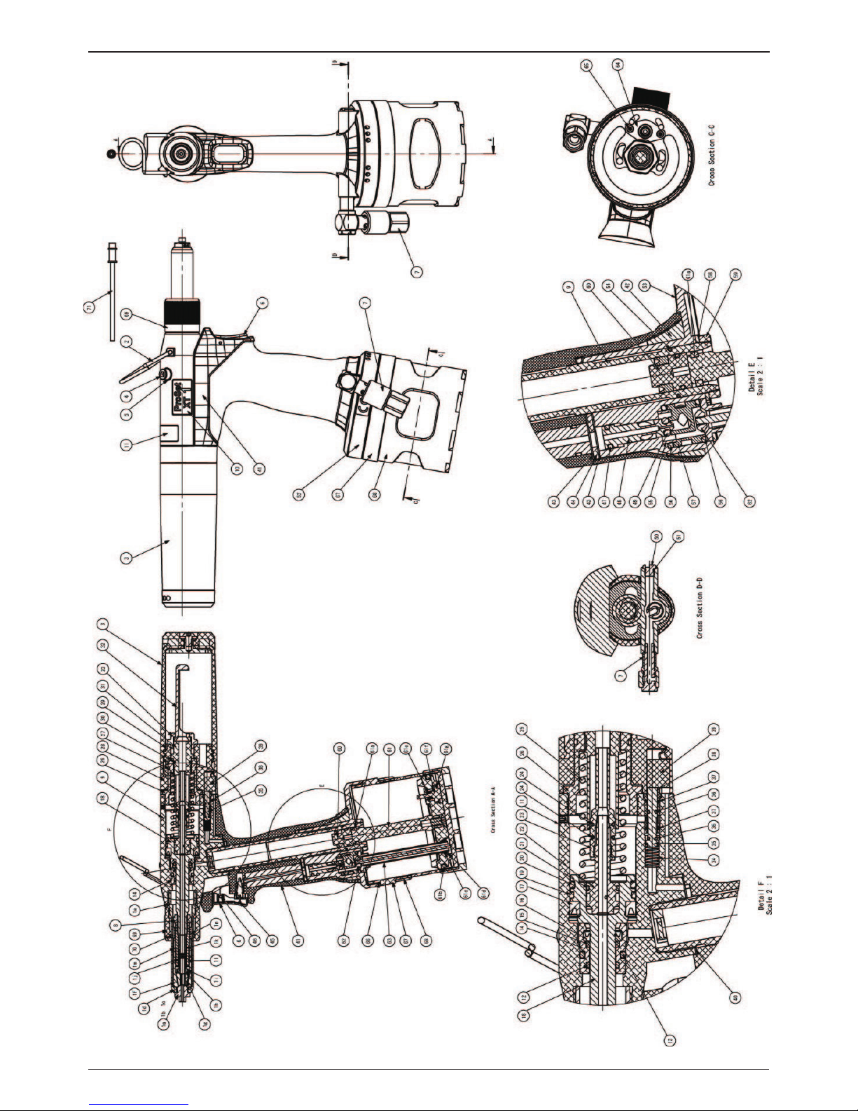
Refer to g. 7 & 8.
6.1 DISMANTLING THE TOOL
NOSE EQUIPMENT
• Unscrew the Nose Housing Nut 69, including O Ring 70, the Nose Housing 1d, the Nose Piece 1a, and
O Ring 1e.
• Pull back the Jaw Guide Lock 1m against the Spring 1n and then unscrew the Jaw Guide 1f.
• Remove the Jaws 1g from the Jaw Guide 1f.
• At this point the Jaws 1g can be cleaned and a light coating of Moly Lithium grease applied or replaced if
worn.
• Remove Jaw Pusher 1h, Urethane Washer 1i, Spring 1j, and Mandrel Guide 1k, from the Pulling Head 1l.
• Using spanners, loosen Locknut 8 and unscrew the Pulling Head 1l, Jaw Guide Lock 1m and Spring 1n
from the Hydraulic Piston 18.
Page 18

18
ENGLISH
Reassemble as follows:
• Any worn or damaged part should be replaced.
• Clean and check wear on Jaws.
• Ensure that the Jaw Pusher 1h, the Spring 1j or Urethane Washer 1h are not distorted.
• Assemble in reverse order to the removal instructions above.
• Lightly coat Jaws 1g with Moly Lithium grease.
• Drop Jaws 1g into the Jaw Guide 1f.
• Insert Jaw Pusher 1h, Urethane Washer 1i, and Mandrel Guide 1k into the Pulling Head 1l.
• Pull back the Jaw Guide Lock 1m and screw the Jaw Guide 1f fully on to the Pulling Head 1l. Release the
Jaw Guide Lock 1m and then partially unscrew the Jaw Guide 1f until the Jaw Guide Lock 1m tooth clicks
into the next slot on the Jaw Guide 1f.
• Place Nose Housing 1d over the Jaw Guide 1f and screw fully onto the tool.
HANDLE UPPER ASSEMBLY
• Rotated the Collector Bottle Assembly 3 anti-clockwise and remove from the Collector Adapter 28. Refer
to g. 1.
• Unscrew the Deector Retaining Nut 33 together with the Stem Deector 32.
• Pull o the Collector Adapter 28.
• Unscrew the End Cap 26 together with O Ring 27 and Ejector Guide 31 and O Ring 30. Care should be
taken as the End Cap will be under load from the Return Spring 25.
• Remove Spring 25.
• Unscrew and remove Locknut 8 from the Pulling Head 1l.
• Push the Hydraulic Piston 18, together with the Ejector Body 22 and O Rings 21 and the Ejector Nozzle
23 and O Rings 24, to the rear and out of the Handle Upper Assembly 9 taking care not to damage the
cylinder bore or piston shaft.
• Push the Rod Seal Case 14, together with the Scraper 12 and O Rings 13 and Bearing Tape 15 and Rod
Seal 16.
• Remove the MCS Valve Case 38 and O Rings 37 and MCS Valve Rod 35 and O Rings 36 and Spring 34 from
the rear of the Handle Upper Assembly 9.
• Once removed check the condition of Rod Seal 16 and discard if damaged.
• Check the condition of Lip Seal 17, Bearing Tape 19 and O Rings 20 on the Hydraulic Piston 18. Remove
and discard if damaged.
• Check the condition of O Rings 24 on the Ejector Nozzle 23. Remove and discard if damaged.
• It should not be necessary to remove the Ejector Nozzle 23 from the Hydraulic Piston 18.
Assemble in reverse order noting the following points:
• Screw Pulling Head 1l by hand until it hits to Hydraulic Piston 18.
• Locknut 8 must be fully tightened onto the Pulling Head 1l.
• Push Rod Seal Case 14 into the Handle Upper Assembly 9 ensuring correct orientation.
• Push Rod Seal Case 14 using the special tool (XT-Jig18) without any fault.
• Ensuring the correct orientation, lubricate and t Piston Seal 17, Bearing Tape 19 and O Ring 20 onto the
Hydraulic Piston 18.
• Lubricate the cylinder bore and the Hydraulic Piston shaft and the seals.
• Push the Hydraulic Piston 18 with the seals into the rear of the Handle Upper Assembly 9 by using the
special tool (XT-Jig18).
• The Hydraulic Piston 18 should be inserted into the Handle Upper Assembly 9 as far as it will go.
AIR CHAMBER AND AIR PISTON ASSEMBLY
• Clamp the Handle Upper Assembly 9 of the inverted tool in a vice with soft jaws.
• Remove the Air Chamber Protector 68.
• Using a wrench, unscrew the Air Chamber 67 including O Ring 66 and remove from the Handle Lower 52
and the Air Piston Assembly 61.
• Remove the Air Piston Assembly 61 together with Guide Ring 61a, O Ring 61b, Mini Y Packing 61c and
the R Type Retaining 61d, EXT Valve Spring 61e, Exhaust Valve Body 61f, CR Type Retaining Ring 61g.
• Engage the seal extractor (07900-00677) into the Intensier Seal Assembly 60 and then withdraw this
from the intensier tube of the Handle Upper Assembly 9.
Page 19

19
ENGLISH
Assemble in reverse order noting the following points:
• Seals should be checked for damage and replaced as necessary. Lubricated pneumatic seals with
Molykote 55M grease (07992-00075) and hydraulic seals with Molykote 111 grease (07900-00755).
• Ensure that the Air Chamber 67 is screwed fully into the Handle Lower 52 so that there are no visible gaps
between the parts. (Tightening Torque:10~12Nm)
AIR VALVE, HANDLE BASE AND HANDLE ASSEMBLY
• Remove the Air Chamber 67 and Air Piston Assembly 61 as described above.
• Using hexagonal wrench (2.5mm), unscrew Hexagonal Socket Head Cap Bolt 65 and remove together
with the Valve Plate 64, Tube Valve Assembly 62 and Tube Assembly 63.
• Unscrew Sleeve Lock Nut 59 and remove together with the Sleeve Washer 58.
• Remove the Handle Lower 52 and Handle Sealing Skirt 42 from the Handle Upper Assembly 9.
• Push the Valve Seat 57 from the Handle Lower 52, together with Valve Seat Sleeve 55 and O Rings 56.
• Pull the Valve Spool Assembly 47, 48, 49, from the Handle Lower 52.
• Pull the Handle Assembly 41 and Handle Sealing Skirt 42 from the Handle Upper Assembly 9.
• Remove Lower Gasket 43, Upper Gasket 44 from the Handle Assembly 41.
• Remove Upper Gasket 40 from the Handle Upper Assembly 9.
Assemble in reverse order noting the following points:
• Seals and gaskets should be checked for damage and replaced as necessary. Lubricated seals and gaskets
with Molykote 55M grease (07992-00075).
• Apply Loctite 243 to Sleeve Lock Nut 59 and tighten to torque 15~20 Nm (11.06~14.75ftlb).
• Ensure that the Air Chamber 67 is screwed fully into the Handle Lower 52 so that there are no visible gaps
between the parts.
TRIGGER
• Using the 2mm Pin Punch (07900-00158) drive the Trigger Pin 46 out of the Handle Assembly 41 and
remove the Trigger Button 6.
• Unscrew the Schrader Valve 45 using the trigger valve extractor (07900-00692).
Page 20

20
ENGLISH
7. TROUBLESHOOTING GUIDE
Symptom Possible Cause Remedy Page Ref.
Tool fails to operate On/O Valve 7 in ‘OFF’ position. On/O Valve (7) to ‘ON’ position. 14
Insucient air pressure. Adjust air pressure to within
specication.
9
Damaged Trigger Valve (45). Replace. 20
Tool does not return fully Air leak. Tighten joints or replace components.
Low air pressure. Adjust air pressure to within
specication.
9
Build up of debris inside the Nose
Equipment (1).
Service and clean Nose Assembly (1). 11, 12, 13
Stem Collector (3 ) removed or not fully
attached.
Check Collector Bottle. 12
More than one operation
of the trigger needed to
place rivet
Air leak. Tighten joints or replace components.
Low air pressure. Adjust air pressure to within
specication.
9
Worn or broken Jaws (1g). Fit new Jaws (1g). 16
Low oil level or air in oil. Prime tool. 14
Build up of debris inside the Nose
Equipment (1).
Service and clean Nose Assembly (1). 13, 16
Collector Bottle (3) removed or not
fully attached.
Check Collector Bottle. 12
Tool will not grip stem
of rivet
Worn or broken Jaws (1g). Fit new Jaws (1g). 16
Broken rivet stems jammed in Nose
Equipment (1).
Service and clean Nose Assembly (1). 13, 16
Loose Jaw Guide (1f). Tighten jaw guide against Pulling
Head (1l).
13, 16
Week or broken Spring (1j). Fit new spring (1j). 13, 16
Incorrect Nose Piece (1a) - (1c) for rivet. Refer to ProSet Nose Equipment
Manual 07900-09412. Select and install
correct nose piece
Incorrect Nose Equipment (1) for rivet. Refer to ProSet Nose Equipment
Manual 07900-09412. Select and install
correct nose equipment
Jaws will not release
broken stem of rivet
Build up of debris inside the Nose
Equipment (1).
Service and clean Nose Assembly (1). 13, 16
Jaw Guide (1f), Nose Piece (1a) or Nose
Housing (1d) not seated correctly.
Correctly assemble aected parts 13, 16
Week or broken Spring (1j). Fit new spring (1j). 10, 13, 15
Excess hydraulic oil or air present in oil. Prime tool. 17
Cannot insert rivet Incorrect Nose Piece (1a) - (1c) for rivet. Refer to ProSet Nose Equipment
Manual 07900-09412. Select and install
correct nose piece
Broken rivet stems jammed in Nose
Equipment (1).
Refer to ProSet Nose Equipment
Manual 07900-09412.
Check Nose Equipment is correct for
rivet
Service and clean Nose Assembly (1). 13, 16
Broken rivet stems jammed in
Hydraulic Piston (18).
Empty Collector Bottle (3). 15
Debris in Nose Piece (1a). Service and clean Nose Assembly (1). 13, 16
Page 21

21
ENGLISH
Symptom Possible Cause Remedy Page Ref.
Slow cycle Low air pressure. Adjust air pressure to within
specication.
9
Build up of debris inside the Nose
Equipment (1).
Service and clean Nose Assembly (1). 13, 16
Collector Bottle (3) removed or not
fully attached.
Check Collector Bottle. 15
Rivet stem does not break Low air pressure. Adjust air pressure to within
specication.
9
Fastener outside tool capability. Refer to Placing Tool Rivet Range &
Nose Equipment table.
11
Incorrect Nose Equipment (1) for
rivet.
Refer to ProSet Nose Equipment
Manual 07900-09412. Select and
install correct nose equipment
Low oil level or air in oil. Prime tool. 17
Low vacuum Stem Collector (3) removed or not
fully attached.
Check Stem Collector. 12
Stem Collector (3) full of stems. Empty Stem Collector (3) 12
Low air pressure. Adjust air pressure to within
specication.
9
Item numbers in bold refer to assembly drawings and parts lists on pages 2, 4, 5 and 6.
Other symptoms or failures should be reported to your local authorised distributor or repair centre.
8. GENERAL SAFETY DATA
8.1 HYSPIN® VG32 OIL SAFETY DATA
8.1.1 FIRST AID
SKIN:
Unlikely to cause harm to the skin on brief or occasional contact but prolonged or exposure may lead to
dermatitis.
Wash skin thoroughly with soap and water as soon as reasonably practicable. Remove heavily contaminated
clothing and wash underlying skin.
Launder contaminated clothing.
ORAL:
Unlikely to cause harm if accidentally swallowed in small doses, though larger quantities may cause nausea
and diarrhea.
If contamination of the mouth occurs, wash out thoroughly with water.
Except as a deliberate act, the ingestion of large amounts of product is unlikely. If it should occur, do not
induce vomiting; obtain medical advice.
Take person to nearest medical centre.
EYES:
Unlikely to cause more than transient stinging or redness if accidental eye contact occurs.
Wash eyes thoroughly with copious quantities of water, ensuring eyelids are held open. Obtain medical advice
if any pain or redness develops or persists.
8.1.2 DISPOSAL:
Remove all spills with inert absorbent material. Ventilate spill area. Place contaminated materials in
a disposable container and dispose in a manner consistent with local regulations.
Page 22

22
ENGLISH
8.1.3 PROTECTING THE ENVIRONMENT:
Separate collection. This product must not be disposed of with normal waste. Should you nd one day that
your product needs replacement, or if it is of no further use to you, do not dispose of it with regular waste.
Make this product available for separate collection. Separate collection of used products and packaging allows
materials to be recycled and used again. Re-use of recycled materials helps prevent environmental pollution
and reduces the demand for raw materials. Local regulations may provide for separate collection of electrical
products, at municipal waste sites or by the retailer when you purchase a new product. You can check the
location of your nearest authorized repair agent by contacting your local STANLEY Engineered Fastening oce
at the address indicated in this manual. Alternatively, a list of authorized repair agents and full details of our
after-sales service and contacts are available on the Internet at: www.StanleyEngineeredFastening.com
8.1.4 FIRE:
FLASH POINT: 200°C.
Extinguish with dry, chemical, foam or carbon dioxide. Do not enter conned space without self-contained
breathing apparatus.
8.1.5 HANDLING:
Use barrier cream or oil resistant gloves.
8.1.6 STORAGE:
Undercover and consistent with local regulations for inammable material.
8.2 MOLY LITHIUM GREASE EP 3753 SAFETY DATA
8.2.1 FIRST AID
SKIN:
As the grease is completely water resistant it is best removed with an approved emulsifying skin cleaner.
ORAL:
Ensure the individual drinks 30ml Milk of Magnesia, preferably in a cup of milk.
EYES:
Irritant but not harmful. Irrigate with water and seek medical attention.
8.2.2 PROTECTING THE ENVIRONMENT:
Scrape up for incineration or disposal on approved site.
8.2.3 FIRE:
FLASH POINT: Above 220°C.
Not classied as ammable.
Suitable extinguishing media: CO2, Halon or water spray if applied by an experienced operator.
8.2.4 HANDLING:
Use barrier cream or oil resistant gloves.
8.2.5 STORAGE:
Away from heat and oxidizing agent.
8.3 MOLYKOTE® 55M GREASE SAFETY DATA
8.3.1 FIRST AID:
SKIN:
Flush with water. Wipe o.
Page 23

23
ENGLISH
INGESTION:
No rst aid should be needed.
EYES:
Flush with water.
8.3.2 PROTECTING THE ENVIRONMENT:
Do not allow large quantities to enter drains or surface waters.
Methods for cleaning up: Scrape up and place in suitable container tted with a lid. The spilled product
produces an extremely slippery surface.
Harmful to aquatic organisms and may cause long-term adverse eects in the aquatic environment. However,
due to the physical form and water - insolubility of the product the bioavailability is negligible.
8.3.3 FIRE:
FLASH POINT: Above 101.1°C. (closed cup)
Explosive Properties: No
Suitable Extinguishing Media: Carbon Dioxide Foam, Dry Powder or ne water spray.
Water can be used to cool re exposed containers.
8.3.4 HANDLING:
General ventilation is recommended. Avoid skin and eye contact.
8.3.5 STORAGE:
Do not store with oxidizing agents. Keep container closed and store away from water or moisture.
8.4 MOLYKOTE® 111 GREASE SAFETY DATA
8.4.1 FIRST AID
SKIN:
No rst aid should be needed.
ORAL:
No rst aid should be needed.
EYES:
No rst aid should be needed.
8.4.2 ENVIRONMENT
No adverse eects are predicted.
8.4.3 FIRE
FLASH POINT: Above 101.1°C. (closed cup)
Explosive Properties: No
Suitable Extinguishing Media: Carbon Dioxide Foam, Dry Powder or ne water spray.
Water can be used to cool re exposed containers.
8.4.4 HANDLING
General ventilation is recommended. Avoid eye contact.
8.4.5 STORAGE
Do not store with oxidizing agents. Keep container closed and store away from water or moisture.
C.O.S.H.H. data for all hydraulic oils and lubricants is available on request from your tool supplier.
Page 24

24
ENGLISH
Find your closest STANLEY Engineered Fastening location on
www.stanleyengineeredfastening.com/contact
For an authorized distributor nearby please check
www.stanleyengineeredfastening.com/econtact/distributors
Manual Number Issue C/N
07900-09408 A 16/298
Avdel UK Limited
Stanley House, Works Road
Letchworth Garden City, Hertfordshire SG6 1JY
Tel. +44 1582 900-000 · Fax -001
enquiries2@sbdinc.com
© 2017 Stanley Black & Decker, Inc.
Avdel®, Avex®, Avibulb®, Avinox®, Avseal®, Avtainer®, Avdelmate®, Avdelok®, Bulbex®, Hemlok®, Interlock®,
Klamp-Tite®, Maxlok®,Monobolt®, POP®, ProSet®, Stavex® and T-Lok® are registered trademarks
of Stanley Black & Decker, Inc. and its aliates.
The names and logos of other companies mentioned herein may be trademarks of their respective owners.
Data shown is subject to change without prior notice as aresult of continuous product development and
improvement policy. Your local STANLEY Engineered Fastening representative is at your disposal should
you need to conrm latest information.
 Loading...