

Stanley ProSet XT1 Blind Rivet Tool, ProSet XT2 Blind Rivet Tool, 76001, 76002 Original Instruction
Page 1
Nose Equipment Manual
Original Instruction
ProSet® XT1 Blind Rivet Tool – 76001
ProSet® XT2 Blind Rivet Tool – 76002
Hydro-Pneumatic Power Tool
Page 2

1
ENGLISH
© 2017 Stanley Black & Decker, Inc.
All rights reserved.
The information provided may not be reproduced and/or made public in any way and through any means
(electronically or mechanically) without prior explicit and written permission from STANLEY Engineered
Fastening. The information provided is based on the data known at the moment of the introduction of this
product. STANLEY Engineered Fastening pursues apolicy of continuous product improvement and therefore
the products may be subject to change. The information provided is applicable to the product as delivered
by STANLEY Engineered Fastening. Therefore, STANLEY Engineered Fastening cannot be held liable for any
damage resulting from deviations from the original specications of the product.
The information available has been composed with the utmost care. However, STANLEY Engineered Fastening
will not accept any liability with respect to any faults in the information nor for the consequences thereof.
STANLEY Engineered Fastening will not accept any liability for damage resulting from activities carried out
by third parties. The working names, trade names, registered trademarks, etc. used by STANLEY Engineered
Fastening should not be considered as being free, pursuant to the legislation with respect to the protection of
trade marks.
CONTENT
1. SAFETY DEFINITIONS ................................................................................................................................. 2
2. SAFETY RULES ............................................................................................................................................3
3. INTENT OF USE ............................................................................................................................................3
4. NOSE EQUIPMENT FOR ProSet® XT1 ......................................................................................................... 4
5. NOSE EQUIPMENT FOR ProSet® XT2 ......................................................................................................... 6
6. BLIND RIVET NOSE ASSEMBLIES FOR ProSet® XT1 .................................................................................. 8
7. BLIND RIVET NOSE ASSEMBLIES FOR ProSet® XT2 ................................................................................ 9
8. AVSEAL NOSE ASSEMBLIES FOR ProSet® XT2 ........................................................................................11
Page 3

2
ENGLISH
This instruction manual must be read by any person installing or operating this tool with particular
attention to the following safety rules.
1. SAFETY DEFINITIONS
The denitions below describe the level of severity for each signal word. Please read the manual and pay
attention to these symbols.
DANGER: Indicates an imminently hazardous situation which, if not avoided, will result in death or
serious injury.
WARNING: Indicates apotentially hazardous situation which, if not avoided, could result in death or
serious injury.
CAUTION: Indicates apotentially hazardous situation which, if not avoided, may result in minor or
moderate injury.
CAUTION: Used without the safety alert symbol indicates apotentially hazardous situation which,
ifnot avoided, may result in property damage.
Improper operation or maintenance of this product could result in serious injury and property damage.
Read and understand all warnings and operating instructions before using this equipment. When using
power tools, basic safety precautions must always be followed to reduce the risk of personal injury.
SAVE ALL WARNINGS AND INSTRUCTIONS FOR FUTURE REFERENCE
WARNING:
• DO NOT use outside the design intent of Placing STANLEY Engineered Fastening Blind Rivets.
• Use only parts, fasteners, and accessories recommended by the manufacturer.
• DO NOT modify the tool in any way. Any modication to the tool is undertaken by the customer and will
be the customer’sentire responsibility and void any applicable warranties.
• Prior to use, check for misalignment or binding of moving parts, breakage of parts, and any other
condition that aects the tool’soperation. If damaged, have the tool serviced before using. Remove any
adjusting key or wrench before use.
• The tool must be maintained in asafe working condition at all times and examined at regular intervals
for damage and function by trained personnel. Any dismantling procedure will be undertaken only by
trained personnel. Do not dismantle this tool without prior reference to the maintenance instructions.
• The operating supply air must not exceed 7 bar (100 PSI).
• Operators and others in work area must wear approved safety glasses with side shields. Always wear
safety glasses and ear protection during operation.
• Dress properly. Do not wear loose clothing or jewellery. Keep your hair, clothing and gloves away from
moving parts. Loose clothes, jewellery or long hair can be caught in moving parts.
• DO NOT operate atool that is directed towards any person(s).
• DO NOT operate tool with the nose casing removed.
• Adopt arm footing or astable position before operating the tool.
• Prior to use, inspect airlines for damage, all connections must be secure. Do not drop heavy objects on
Hoses. Asharp impact may cause internal damage and lead to premature hose failure.
• DO NOT lift the placing tool by the hose. Always use the placing tool handle.
• Vent holes must not become blocked or covered.
• Disconnect the air hose from the tool before performing any maintenance, attempting to adjust, t or
remove anose assembly.
• Keep tool handles dry, clean, and free from oil and grease.
• When carrying the tool from place to place keep hands away from the trigger to avoid inadvertent
activation.
Page 4

3
ENGLISH
• Never leave operating tool unattended. Disconnect air hose when tool is not in use.
• Adequate clearance is required for the tool operator’shands before proceeding.
• DO NOT abuse the tool by dropping or using it as ahammer.
STANLEY Engineered Fastening policy is one of continuous product development and improvement
and we reserve the right to change the specication of any product without prior notice
2. SAFETY RULES
This technical datasheet must be read with particular attention to the safety warnings and operating
instructions listed in the ProSet XT1 and ProSet XT2 Instruction Manual, by any person tting or
operating the nose assemblies and hand tools.
3. INTENT OF USE
The nose equipment in combination with the ProSet XT1 and ProSet XT2 tools are designed for placing
Stanley Engeered Fastening blind rivets only. The correct placing tool and nose assembly must be selected for
each for each rivet type and size as shown in the tables on pages 5 and 7.
Page 5
4
ENGLISH
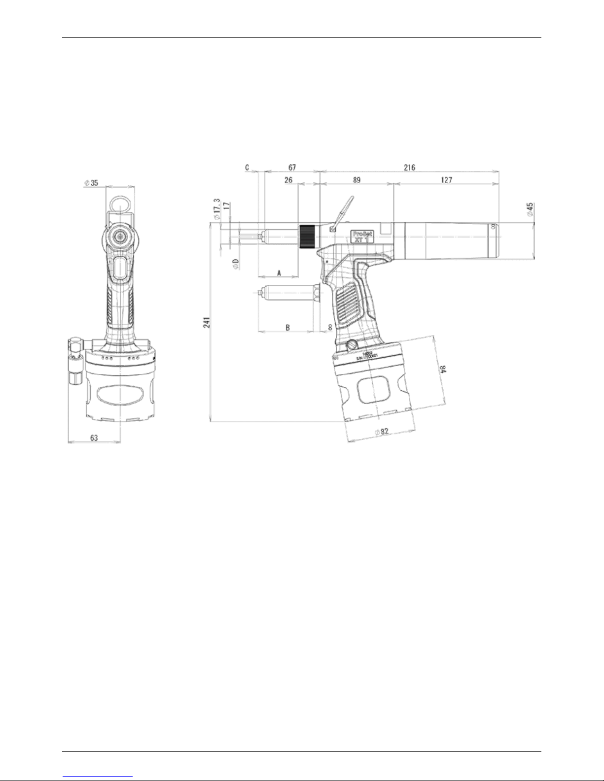
4. NOSE EQUIPMENT FOR ProSet® XT1
Nose equipment varies according to the rivet type being installed. Each nose assembly represents aunique
set of components which can be ordered individually. For assembly dimensions ‘A’, ‘B’, ‘C’ and ‘D’ refer to Nose
Equipment tables on page 5. We recommend maintaining some stock of spares as items will need regular
replacement if worn.
Fig. 1
Dimensions in millimetres (mm) – Illustration shown with the standard nose assembly TRM00360 and nose tip
PRN414 tted. Tool appearance will vary with dierent nose assemblies tted.
Page 6

5
ENGLISH
RIVET
TYPE
RIVET
DIAMETER
RIVET
MATERIAL
NOSE
ASSEMBLY
NOSE
TIP
JAW
PUSHER
MANDREL
GUIDE
DIMENSION (mm)
NOTES
A B C D
OPEN END
2,4 3/32
AL. ALLOY
STEEL
BODY
TRM00360 PRN314 TP144-117 TP144-178 49,9 67,9 8,9 4,6
3,2 1/8 TRM00360 PRN414 TP144-117 TP144-120 49,9 67,9 8,9 5,3
4,0 5/32 TRM00360 PRN514 TP144-117 TP144-120 49,9 67,9 8,9 6,7
4,8 3/16
5,0 -
OPEN END
3,2 1/8
STAINLESS
BODY
TRM00360 PRN414 TP144-117 TP144-120 49,9 67,9 8,9 5,3
4,0 5/32
4,8 3/16
CLOSED END
3,2 1/8
AL. ALLOY
BODY
TRM00360 PRN424 TP144-117 TP144-120 48,6 66,6 7,6 5,3
4,0 5/32 TRM00360 PRN524 TP144-117 TP144-120 49,4 67,4 8,4 6,7
4,8 3/16
CLOSED END
3,2 1/8
STAINLESS
BODY
TRM00360 PRN434 TP144-117 TP144-120 48,6 66,6 7,6 5,3
4,0 5/32
4,8 3/16
BHM RIVET
2,4 3/32
AL. ALLOY
STEEL
BODY
TRM00360 PRN314 TP144-117 TP144-178 49,9 67,9 8,9 4,6
3,2 1/8 TRM00360 PRN414 TP144-117 TP144-120 49,9 67,9 8,9 5,3
4,0 5/32 TRM00360 PRN514 TP144-117 TP144-120 49,9 67,9 8,9 6,7
4,8 3/16
BHM RIVET
2,4 3/32
STAINLESS
BODY
3,2 1/8 TRM00360 PRN414 TP144-117 TP144-120 49,9 67,9 8,9 5,3
4,0 5/32
4,8 3/16
TLrivets®
4,0 5/32
AL. ALLOY
BODY
TRM003601) PRN514 TP144-117 TP144-120 49,9 67,9 8,9 6,7
4,8 3/16
PEEL RIVET
3,2 1/8
AL. ALLOY
BODY
TRM00360 PRN414 TP144-117 TP144-120 49,9 67,9 8,9 5,3
4,0 5/32 TRM00360 PRN514 TP144-117 TP144-120 49,9 67,9 8,9 6,7
4,8 3/16
HRrivets®
3,2 1/8
AL. ALLOY
BODY
AL. ALLOY STEM
TRM00360 PRN4K TP144-117 TP144-120 48,0 66,0 7,0 5,0
4,0 5/32 TRM00360 PRN5K TP144-117 TP144-120 48,5 66,5 7,5 6,1
4,8 3/16
HRrivets®
3,2 1/8
AL. ALLOY
BODY
STEEL STEM
TRM00360 PRN414 TP144-117 TP144-120 49,9 67,9 8,9 5,3
4,0 5/32 TRM00360 PRN514 TP144-117 TP144-120 49,9 67,9 8,9 6,7
4,8 3/16
HRrivets®
3,2 1/8
STEEL
BODY
TRM00360 PRN4K TP144-117 TP144-120 48,0 66,0 7,0 5,0
4,0 5/32
4,8 3/16
HRrivets®
3,2 1/8
STAINLESS
BODY
TRM00360 PRN4K TP144-117 TP144-120 48,0 66,0 7,0 5,0
4,0 5/32
4,8 3/16
T-RIVET 4,8 3/16 ALL
AVEX®
3,2 1/8
AL. ALLOY
BODY
TRM00360 PRN414 TP144-117 TP144-120 49,9 67,9 8,9 5,3
4,0 5/32 TRM00360 PRN514 TP144-117 TP144-120 49,9 67,9 8,9 6,7
4,8 3/16
AVEX®
3,2 1/8
STEEL
BODY
TRM00360 PRN4K TP144-117 TP144-120 48,0 66,0 7,0 5,0
4,0 5/32
4,8 3/16
STAVEX®
3,2 1/8
ALL
TRM00360 PRN4K TP144-117 TP144-120 48,0 66,0 7,0 5,0
4,0 5/32
4,8 3/16
AVINOX®
3,2 1/8
ALL
TRM00360 PRN4K TP144-117 TP144-120 48,0 66,0 7,0 5,0
4,0 5/32
4,8 3/16
AVIBULB®
3,2 1/8
ALL
TRM00360 PRN4K TP144-117 TP144-120 48,0 66,0 7,0 5,0
4,0 5/32
4,8 3/16
BULBEX®
4,0 5/32
ALL
TRM003601) PRN514 TP144-117 TP144-120
49,9 67,9 8,9 6,7
4,8 3/16
T-LOK®
4,0 5/32
ALL
4,8 3/16
AVDEL SR®
3,2 1/8
ALL
TRM00360 PRN414 TP144-117 TP144-120 49,9 67,9 8,9 5,3
4,0 5/32 TRM00360 PRN514 TP144-117 TP144-120 49,9 67,9 8,9 6,7
4,8 3/16
INTERLOCK® 4,8 3/16 ALL
MONOBOLT® 4,8 3/16 ALL
Q RIVET®
3,2 1/8
ALL
TRM00360 PRN414 TP144-117 TP144-120 49,9 67,9 8,9 5,3
4,0 5/32
4,8 3/16
KLAMP-TITE® 4,8 3/16 ALL
AVSEALE® II
4,0 -
AL. ALLOY
STEEL
BODY
5,0 6,0 7,0 -
1) XT1 cannot place rivet in one stroke.
Page 7

6
ENGLISH
5. NOSE EQUIPMENT FOR ProSet® XT2
Nose equipment varies according to the rivet type being installed. Each nose assembly represents aunique
set of components which can be ordered individually. For assembly dimensions ‘A’, ‘ B’, ‘C’ and ‘D’ refer to Nose
Equipment table on page 7. We recommend maintaining some stock of spares as items will need regular
replacement if worn.
Fig. 2
Dimensions in millimetres (mm) – Illustration shown with the standard nose assembly TRM00361 and nose tip
PRN614 tted. Tool appearance will vary with dierent nose assemblies tted.
Page 8

7
ENGLISH
RIVET
TYPE
RIVET
DIAMETER
RIVET
MATERIAL
NOSE
ASSEMBLY
NOSE
TIP
JAW
PUSHER
MANDREL
GUIDE
DIMENSION NOTES
A B C D
OPEN END
2,4 3/32
AL. ALLOY
STEEL
BODY
3,2 1/8 TRM00361 PRN414 TRM00355 TRM00261 53,9 71,9 8,9 5,3
4,0 5/32 TRM00361 PRN514 TRM00355 TRM00261 53,9 71,9 8,9 6,7
4,8 3/16 TRM00361 PRN614 TP144-050 TP144-052 53,9 71,9 8,9 6,7
5,0 - TRM00361 PRN614 TP144-050 TP144-052 53,9 71,9 8,9 6,7
OPEN END
3,2 1/8
STAINLESS
BODY
TRM00361 PRN414 TRM00355 TRM00261 53,9 71,9 8,9 5,3
4,0 5/32 TRM00361 PRN514 TRM00355 TRM00261 53,9 71,9 8,9 6,7
4,8 3/16 TRM00361 PRN614 TP144-050 TP144-052 53,9 71,9 8,9 6,7
CLOSED END
3,2 1/8
AL. ALLOY
BODY
TRM003611) PRN424 TRM00355 TRM00261 52,6 70,6 7,6 5,3
4,0 5/32 TRM00361 PRN524 TRM00355 TRM00261 53,4 71,4 8,4 6,7
4,8 3/16 TRM00361 PRN624 TP144-050 TP144-052 53,6 71,6 8,6 8,1
CLOSED END
3,2 1/8
STAINLESS
BODY
TRM00361 PRN434 TRM00355 TRM00261 52,6 70,6 7,6 5,3
4,0 5/32 TRM00361 PRN534 TRM00355 TRM00261 53,4 71,4 8,4 6,7
4,8 3/16 TRM003612) PRN634 TP144-050 TP144-052 53,6 71,6 8,6 8,1
BHM RIVET
2,4 3/32
AL. ALLOY
STEEL
BODY
3,2 1/8 TRM00361 PRN414 TRM00355 TRM00261 53,9 71,9 8,9 5,3
4,0 5/32 TRM00361 PRN514 TRM00355 TRM00261 53,9 71,9 8,9 6,7
4,8 3/16 TRM00361 PRN614 TP144-050 TP144-052 53,9 71,9 8,9 6,7
BHM RIVET
2,4 3/32
STAINLESS
BODY
63,0
3,2 1/8 TRM00361 PRN414 TRM00355 TRM00261 53,9 71,9 8,9 5,3
4,0 5/32 TRM00361 PRN514 TRM00355 TRM00261 53,9 71,9 8,9 6,7
4,8 3/16
TLrivets®
4,0 5/32
AL. ALLOY
BODY
TRM003613) PRN514 TRM00355 TRM00261 53,9 71,9 8,9 6,7
4,8 3/16 TRM003613) PRN614 TP144-050 TP144-052 53,9 71,9 8,9 6,7
PEEL RIVET
3,2 1/8
AL. ALLOY
BODY
TRM00361 PRN414 TRM00355 TRM00261 53,9 71,9 8,9 5,3
4,0 5/32 TRM00361 PRN514 TRM00355 TRM00261 53,9 71,9 8,9 6,7
4,8 3/16 TRM00361 PRN614 TP144-050 TP144-052 53,9 71,9 8,9 6,7
HRrivets®
3,2 1/8
AL. ALLOY BODY
AL. ALLOY STEM
TRM00361 PRN4K TRM00355 TRM00261 52,0 70,0 7,0 5,0
4,0 5/32 TRM00361 PRN5K TP144-050 TP144-052 52,5 70,5 7,5 6,1
4,8 3/16 TRM00361 PRN6K TP144-050 TP144-052 52,0 70,0 7,0 7,8
HRrivets®
3,2 1/8
AL. ALLOY BODY
STEEL STEM
TRM00361 PRN4K TRM00355 TRM00261 52,0 70,0 7,0 5,0
4,0 5/32 TRM00361 PRN5K TP144-050 TP144-052 52,5 70,5 7,5 6,1
4,8 3/16 TRM00361 PRN6K TP144-050 TP144-052 52,0 70,0 7,0 7,8
HRrivets®
3,2 1/8
STEEL
BODY
TRM00361 PRN414 TRM00355 TRM00261 53,9 71,9 8,9 5,3
4,0 5/32 TRM00361 PRN514 TRM00355 TRM00261 53,9 71,9 8,9 6,7
4,8 3/16 TRM00361 PRN614 TP144-050 TP144-052 53,9 71,9 8,9 6,7
HRrivets®
3,2 1/8
STAINLESS
BODY
TRM00361 PRN4K TRM00355 TRM00261 52,0 70,0 7,0 5,0
4,0 5/32 TRM00361
PRN5K TP144-050 TP144-052 52,5 70,5 7,5 6,1
4,8 3/16
T-RIVET 4,8 3/16 ALL TRM00361 PRN614 TP144-050 TP144-052 53,9 71,9 8,9 6,7
AVEX®
3,2 1/8
AL. ALLOY
BODY
TRM00361 PRN414 TRM00355 TRM00261 53,9 71,9 8,9 5,3
4,0 5/32 TRM00361 PRN514 TRM00355 TRM00261 53,9 71,9 8,9 6,7
4,8 3/16 TRM00361 07381-04701 TP144-050 TP144-052 47,8 65,8 2,8 12,7
AVEX®
3,2 1/8
STEEL
BODY
TRM00361 PRN4K TRM00355 TRM00261 52,0 70,0 7,0 5,0
4,0 5/32 TRM00361 PRN5K TRM00355 TRM00261 52,5 70,5 7,5 6,1
4,8 3/16 TRM00361 PRN6K TP144-050 TP144-052 52,0 70,0 7,0 7,8
STAVEX®
3,2 1/8
ALL
TRM00361 PRN4K TRM00355 TRM00261 52,0 70,0 7,0 5,0
4,0 5/32 TRM00361 PRN5K TP144-050 TP144-052 52,5 70,5 7,5 6,1
4,8 3/16 TRM00361 PRN614 TP144-050 TP144-052 53,9 71,9 8,9 6,7
AVINOX®
3,2 1/8
ALL
TRM00361 PRN4K TRM00355 TRM00261 52,0 70,0 7,0 5,0
4,0 5/32 TRM00361 PRN514 TP144-050 TP144-052 53,9 71,9 8,9 6,7
4,8 3/16 TRM00361 PRN614 TP144-050 TP144-052 53,9 71,9 8,9 6,7
AVIBULB®
3,2 1/8
ALL
TRM00361 PRN4K TRM00355 TRM00261 52,0 70,0 7,0 5,0
4,0 5/32 TRM00361 PRN514 TP144-050 TP144-052 53,9 71,9 8,9 6,7
4,8 3/16 TRM00361 PRN614 TP144-050 TP144-052 53,9 71,9 8,9 6,7
BULBEX®
4,0 5/32
ALL
TRM003613) PRN514 TRM00355 TRM00261 53,9 71,9 8,9 6,7
4,8 3/16 TRM003613) PRN614 TP144-050 TP144-052 53,9 71,9 8,9 6,7
T-LOK®
4,3 5/32
ALL
TRM00361 PRN514 TRM00355 TRM00261 53,9 71,9 8,9 6,7
4,8 3/16 TRM00361 07381-04701 TP144-050 TP144-052 47,8 65,8 2,8 12,7
AVDEL SR®
3,2 1/8
ALL
TRM00361 PRN414 TRM00355 TRM00261 53,9 71,9 8,9 5,3
4,0 5/32 TRM00361 PRN514 TRM00355 TRM00261 53,9 71,9 8,9 6,7
4,8 3/16 TRM00361 PRN614 TP144-050 TP144-052 53,9 71,9 8,9 6,7
INTERLOCK® 4,8 3/16 ALL TRM00361 PRN614 TP144-050 TP144-052 53,9 71,9 8,9 6,7
MONOBOLT® 4,8 3/16 ALL TRM00361 71210-16020 TP144-050 TP144-052 49,1 67,1 4,1 12,7
Q RIVET®
3,2 1/8
ALL
TRM00361 PRN414 TRM00355 TRM00261 53,9 71,9 8,9 5,3
4,0 5/32 TRM00361 PRN514 TRM00355 TRM00261 53,9 71,9 8,9 6,7
4,8 3/16 TRM00361 07381-04701 TP144-050 TP144-052 47,8 65,8 2,8 12,7
KLAMP-TITE® 4,8 3/16 ALL TRM00361 PRN614 TP144-050 TP144-052 53,9 71,9 8,9 6,7
AVSEAL® II
4,0
-
AL. ALLOY
STEEL
BODY
76002-
16100 4)
71219-11346
07498-04502 -
49,4 67,4 4,4 12,7 1mm extended nose tip
- 71210-16106 50,5 68,5 5,5 12,7 2mm extended nose tip
- 71210-16110 56,5 74,5 11,5 12,7 8mm extended nose tip
5,0
-
AL. ALLOY
STEEL
BODY
76002-
16100 4)
71219-11347
07498-04502 -
49,4 67,4 4,4 12,7 1mm extended nose tip
- 71210-16107 50,5 68,5 5,5 12,7 2mm extended nose tip
- 71210-16111 56,5 74,5 11,5 12,7 8mm extended nose tip
6,0
AL. ALLOY
STEEL
BODY
76002-
16100 4)
71210-16104
07498-04502 -
47,5 65,5 2,5 12,7
Flush nose tip
- 71219-11348 49,4 67,4 4,4 12,7 1mm extended nose tip
- 71210-16108 50,5 68,5 5,5 12,7 2mm extended nose tip
- 71210-16112 56,5 74,5 11,5 12,7 8mm extended nose tip
7,0
AL. ALLOY
STEEL
BODY
76002-
16100 4)
71210-16105
07498-04502 -
47,5 65,5 2,5 12,7 Flush type nose tip
- 71219-11349 49,4 67,4 4,4 12,7 1mm extended nose tip
- 71210-16109 50,5 68,5 5,5 12,7 2mm extended nose tip
- 71210-16113 56,5 74,5 11,5 12,7 8mm extended nose tip
1) When the mandrel diameter is φ1.6, use 71200-15001 Jaw.
2) The air supply pressure required is 0.60MPa or greater.
3) The XT2 cannot place rivet in one stroke.
4) Refer to page 11 & 12.
Page 9

8
ENGLISH
6. BLIND RIVET NOSE ASSEMBLIES FOR ProSet® XT1
TRM00360
Fig. 3
2
3
6
141)
4
13
9
8
10
11
12
1a, 1b, 1c
5
7
1) For rivet diameters of 2.4mm, use TP144-178 (Mandrel Guide Assembly).
Part Number: TRM00360
Item Part Number Description Qty
1a PRN414 Nose Piece 1
1b PRN314 Nose Piece 1
1c PRN514 Nose Piece 1
2 TP144-111 Nose Housing 1
3 DPN239-006 Jaw Guide 1
4 PRG402-8A Jaws 1set
5 TP144-117 Jaw Pusher 1
6 TP144-118 Urethane Washer 1
7 TP144-119 Jaw Pusher Spring 1
8 TRM00167 Pulling Head 1
9 TP144-120 Mandrel Guide 1
10 TP144-113 Jaw Guide Lock 1
11 TP144-114 Jaw Guide Lock Spring 1
12 TP144-115 Lock Nut 1
13 TP144-091 O-Ring 1
14 TP144-178 Mandrel Guide Assembly 1
Page 10

9
ENGLISH
7. BLIND RIVET NOSE ASSEMBLIES FOR ProSet® XT2
TRM00361
Fig. 4
2
151)
6
12
11
10
8
9
4
3
13
1a, 1b, 1c
141)
7
5
1) For rivet diameters of 3.2 or 4.0, use TRM00355 (Jaw Pusher) and TRM00261 (Mandrel Guide Assembly).
Part Number: TRM00361
Item Part Number Description Qty
1a PRN614 Nose Piece 1
1b PRN514 Nose Piece 1
1c PRN414 Nose Piece 1
2 TP144-048 Nose Housing 1
3 DPN275-001 Jaw Guide 1
4 71210-15001 Jaws 1set
5 TP144-050 Jaw Pusher 1
6 TP144-088 Urethane Washer 1
7 TP144-081 Jaw Pusher Spring 1
8 TRM00165 Pulling Head 1
9 TP144-052 Mandrel Guide 1
10 TP144-051 Jaw Guide Lock 1
11 TP144-080 Jaw Guide Lock Spring 1
12 TP144-060 Lock Nut 1
13 TP144-091 O-Ring 1
14 TRM00355 Jaw Pusher 1
15 TRM00261 Mandrel Guide Assembly 1
Page 11

10
ENGLISH
FITTING INSTRUCTIONS
IMPORTANT - READ THE SAFETY WARNINGS LISTED IN THE PROSET XT1 AND PROSET XT2 INSTRUCTION
MANUAL CAREFULLY BEFORE PUTTING INTO SERVICE.
IMPORTANT - THE AIR SUPPLY MUST BE TURNED OFF OR DISCONNECTED BEFORE FITTING OR
REMOVING THE NOSE EQUIPMENT.
Item numbers in bold refer to the components in gure 3 & 4 and the tables on pages 8 & 9.
• The air supply must be disconnected.
• Rotate Nose Housing (2) anti-clockwise and remove together with Nosepiece (1).
• Rotate Jaw Guide (3) anti-clockwise and remove together with Jaws (4).
• Remove Jaw Pusher (5) together with Urethane Washer (6), Jaw Pusher Spring (7) from Pulling Head (8).
• Remove Mandrel Guide (9) from Pulling Head (8).
• Insert “adapted Mandrel Guide” (9), Jaw Pusher Spring (7), Urethane Washer (6) and “adapted Jaw Pusher”
(5) to Pulling Head (8).
• Lightly coat Jaws (4) with moly lithium grease.
• Drop Jaws (4) into the Jaw Guide (3).
• Pull back Jaw Guide Lock (10) and screw Jaw Guide (3) fully on to Pulling Head (8).
• Release Jaw Guide Lock (10) and then partially unscrew Jaw Guide (3) until Jaw Guide Lock (10) tooth
clicks into the next slot on Jaw Guide (3).
• Rotate Nosepiece (1) anti-clockwise and remove from Nose Housing (2).
• Replace with the Nosepiece (1) specied for the rivet to be placed.
• Screw Nose Housing (2) together with Nosepiece (1) to tool.
• The tool is now ready to place the required rivet.
SERVICING INSTRUCTIONS
• Nose Equipments need to be serviced at weekly intervals or every 3,000 cycles. Hold some stock of all
internal components of Nose Equipment and Nosepieces, they need regular replacement.
• The air supply must be disconnected.
• Remove Nose Housing (2), including Nosepiece (1), and O-Ring (13) from the tool.
• Pull back Jaw Guide Lock (10) against Jaw Guide Lock Spring (11) and then remove Jaw Guide (3).
• Remove the Jaws (4) from Jaw Guide (3).
• Remove Jaw Pusher (5), Urethane Washer (6), and Jaw Pusher Spring (7), from Pulling Head (8).
• Rotate Lock Nut (12) anti-clockwise and remove Pulling Head (8), Jaw Guide Lock (10), Jaw Guide Lock
Spring (11) from the tool piston using spanners.
• Inspect all components. Any worn or damaged parts must be replaced by anew part.
• Particularly check wear Jaws (4).
• Clean all parts and apply moly lithium Grease (07992-00020) to Jaws (4) and taper bore of Jaw Guide (3).
• Assemble according to tting instructions above.
Page 12

11
ENGLISH
8. AVSEAL NOSE ASSEMBLIES FOR ProSet® XT2
76002-16100
Fig. 5
Part Number: 76002-16100
Item Part Number Description Qty
1 76002-16001 Nose Casing 1
2 76002-16003 Jaw Guide 1
3 71210-16101 Jaws 1set
4 07498-04502 Jaw Spreader 1
5 71210-05001 Buer 1
6 76002-16002 Pulling Head 1
7 TP144-051 Jaw Guide Lock 1
8 07500-00418 Jaw Spring 1
9 TP144-080 Jaw Guide Lock Spring 1
10 TP144-060 Lock Nut 1
11 TP144-091 O-Ring 1
FITTING INSTRUCTIONS
IMPORTANT - READ THE SAFETY WARNINGS LISTED IN THE PROSET XT3 AND PROSET XT4 INSTRUCTION
MANUAL CAREFULLY BEFORE PUTTING INTO SERVICE.
IMPORTANT - THE AIR SUPPLY MUST BE TURNED OFF OR DISCONNECTED BEFORE FITTING OR
REMOVING THE NOSE ASSEMBLY.
Item numbers in bold refer to the components in gure 5 and the table on pages 11.
Page 13

12
ENGLISH
• The air supply must be disconnected.
• Remove the complete nose assembly TRM00361 as described in the Proset XT2 instruction manual.
• Screw Pulling Head (6) together with Jaw Guide Lock (7), Jaw Guide Lock Spring (9) to the tool piston and
then tighten Lock Nut (10) to Pulling Head (6).
• Attach Jaw Spreader (4) together with Buer (5) and Jaw Spring (8) to Pulling Head (6).
• Install Jaw Guide (2) together with Jaws (3) to Pulling Head (6).
• Screw Nose Casing (1) together with required Nosepiece and O-Ring (11) to Handle Upper.
• The tool is now ready to place Avseal rivets.
SERVICING INSTRUCTIONS
• Nose Equipments need to be serviced at weekly intervals or every 3,000 cycles. Hold some stock of all
internal components of Nose Equipment and Nosepieces, they need regular replacement.
• The air supply must be disconnected.
• Remove Nose Casing (2), including Nosepiece, and O-Ring (11) from the tool.
• Pull back Jaw Guide Lock (7) against Jaw Guide Lock Spring (9) and then remove Jaw Guide (2).
• Remove Jaws (3) from Jaw Guide (2).
• Remove Jaw Spreader (4), Buer (5), and Jaw Spring (8), from Pulling Head (6).
• Rotate Lock Nut (10) anti-clockwise and remove Pulling Head (6), Jaw Guide Lock (7), Jaw Guide Lock
Spring (9) from the tool piston using spanners.
• Inspect all components. Any worn or damaged parts must be replaced by anew part.
• Particularly check wear Jaws (3).
• Clean all parts and apply moly lithium Grease (07992-00020) to Jaws (3) and taper bore of Jaw Guide (2).
• Assemble according to tting instructions above.
Page 14

For an authorized distributor nearby please check
www.StanleyEngineeredFastening.com/econtact/distributors
Manual Number Issue C/N
07900-09412 A 17/143
STANLEY Engineered Fastening
Avdel UK Limited
Stanley House, Works Road
Letchworth Garden City, Hertfordshire SG6 1JY
Tel. +44 1582 900-000 . Fax -001
Enquiries2@sbdinc.com
© 2017 Stanley Black & Decker, Inc.
Avdel®, Avex®, Avibulb®, Avinox®, Avseal®, Bulbex®, Hemlok®, Interlock®, Klamp-Tite®, Monobolt®,
POP®, ProSet®, Stavex® and T-Lok® are registered trademarks of Stanley Black & Decker, Inc. and its aliates.
The names and logos of other companies mentioned herein may be trademarks of their respective owners.
Data shown is subject to change without prior notice as a result of continuous product development and
improvement policy. Your local STANLEY Engineered Fastening representative is at your disposal should
you need to conrm latest information.
 Loading...