

Page 1
Stanley Access Technologies
Quick-Reference Guide
STANLEY
MAKE SOMETHING GREAT™
7400-Series ICU Door System
Installation Instructions
Quick-Reference Guide
204068
Rev. B, 2/26/11
Prohibition on Copying
Any unauthorized reproduction, disclosure or distribution of copies by any person of any
portion of this work may be a violation of copyright law of the United States of America
and other countries, could result in the awarding of statutory damages of up to $250,000
(17 USC 504) for infringement, and may result in further civil and criminal penalties. All
rights reserved.
Page 2
Stanley Access Technologies
Quick-Reference Guide
TABLE OF CONTENTS
1. PURPOSE....! 2
1.1 Discussion 2
1.2 Applicability 2
1.3 Features and Functions 2
2. PREREQUISITES 2
3. INSTALLATION INSTRUCTIONS 3
3.1 Checking the Rough Opening 3
3.2 Attaching the Jambs to the Header (l3// Header Option) 3
3.3 Attaching the Jambs to the Header (41/2" Header Option) 4
3.4 Installing the Header and Jamb Assembly 5
3.5 Installing the Door Panels 6
3.6 Installing the Door Handle and Paddle Assembly 6
3.7 Installing the Latch Post Assembly 6
3.8 Attaching the Door Closer Assembly 6
3.9 Installing the Optional Smoke Seals 6
3.10 Performing the Closeout Procedure 7
3.1 Replacement Parts 10
Attachments
Attachment I, Documents, Definitions, Tools, Equipment, Materials, and Consumables 11
Attachment 2, Latch Assembly Installation 12
Attachment 3, Header and Smoke Seal Options 13
© 2011, THE STANLEY WORKS. ALL RIGHTS RESERVED.
204068
Rev. B, 2/26/11
1 of 15
Page 3

1. PURPOSE
1.1 Discussion
This manual provides installation instructions for the Stanley 7400-Series ICU door system. The
7400-Series ICU door is a fully manual door system that features either two swinging panels or
one swing door (single). The most common application for the door system is a hospital
intensive care unit.
1.2 Applicability
This manual is applicable to the Stanley 7400-Series ICU door system.
1.3 Features and Functions
The 7400-Series ICU door system includes the following features:
• For active panels, a swing-door closer assembly embedded in the panel and header.
(Inactive panels use a flush bolt and do not have a closer.) The closer assembly includes
two setscrews. One screw adjusts the door closing speed as it closes from 105° to 15°. The
other screw adjusts the latch closing speed throughout the last 15°.
• A 105° hold-open feature. When the swing door is opened to greater than 105° the door
closer holds it open.
• Flush bolt on the inactive panel
• Lever handle and push handle on the active panels
• Smoke and draft option
• Continuous hinges
2. PREREQUISITES
2.1 Protective barrier (caution/warning tape) has been set up to prevent unauthorized access to work
area.
2.2 Attachment 1 has been reviewed for the following:
• Definitions of the terms used in this procedure
• A listing of the additional documents required during this procedure
• A listing of the tools, equipment, materials, and consumables used in this procedure.
204068
Rev. B, 2/26/11
12011. THE STANLEY WORKS, ALL RIGHTS RESERVED. 2 of 1 5
Page 4

3. INSTALLATION INSTRUCTIONS
3.1 Checking the Rough Opening
3.1.1 ENSURE floor is level across the entire opening.
NOTE
The door shall be installed within the rough opening such that an average clearance between the door and
rough opening is V/ along the pivot and top edge; Vg" along the lead edge for a single panel; V/ along the
bottom; and Vie" along the meeting edge for a pair.
3.1.2 CHECK opening width.
3.1.3 CHECK opening height ivvm finished floor.
3.1.4 SWEEP floor.
3.2 Attaching the Jambs to the Header (I3//' Header Option)
3.2.1 Refer to Figure 1, and, using one 'A -20 X screw and one 'A -20 X 1 l/f screw with
spring lockwashers, ATTACH header bracket to rivnuts in jamb.
3.2.2 POSITION end of header extrusion over the header bracket.
3.2.3 Using four Va -20 X V/ CS screws, ATTACH header to header bracket.
3.2.4 REPEAT Section 3.2 for opposite end of header.
©2011, THE STANLEY WORKS. ALL RIGHTS RESERVED.
204068
Rev. B, 2/26/11
3 of 15
Page 5
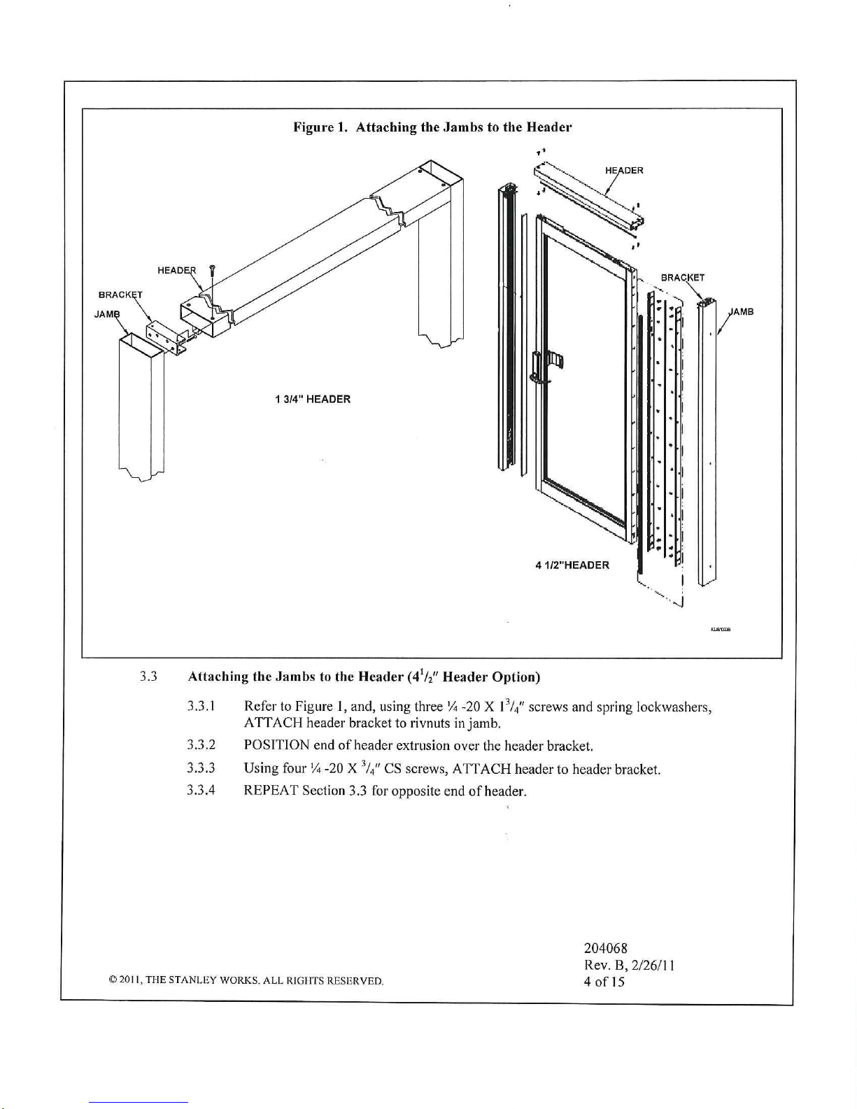
3.3.1 Refer to Figure 1, and, using three % -20 X l3// screws and spring lockwashers,
ATTACH header bracket to rivnuts in jamb.
3.3.2 POSITION end of header extrusion over the header bracket.
3.3.3 Using four 'A -20 X V/ CS screws, ATTACH header to header bracket.
3.3.4 REPEAT Section 3.3 for opposite end of header.
©2011, THE STANLEY
WORKS. ALL RIGHTS RESERVED.
204068
Rev. B, 2/26/11
4 of 15
Page 6

3.4 Installing the Header and Jamb Assembly
3.4.1 LIFT header and jamb assembly and POSITION into opening.
3.4.2 Temporarily SECURE frame in place as necessary to prevent header and jamb assembly
from falling,
3.4.3 SHIM beneath jamb(s) as necessary to level header and maintain required height from
highest point of finished floor.
3.4.4 INSPECT one jamb for plumb in vertical and horizontal planes. IF required, SHIM
back of jamb.
3.4.5 Refer to Figure 2, and, using the previously drilled jamb holes as a guide, DRILL holes
in rough opening for the following fasteners as required:
• IF rough opening is concrete, DRILL W dia. hole for concrete screw, and
ENSURE screw will be embedded VA" minimum.
• IF rough opening is steel, DRILL #14 SMS (Note 18 GA steel minimum).
• IF rough opening is wood, DRILL for #14 wood screw, and ENSURE screw will
be embedded 1 Vi" minimum.
.>
Figure 2. Installing the Header and Jamb Assembly
— ^
(D
-—^^
— U d-J
1 1 . SI
3.4.6 INSTALL, but do not tighten, fasteners securing one jamb to opening, and ENSURE
jamb remains plumb.
3.4.7 INSPECT opposite jamb for plumb in vertical and horizontal planes. IF required, SHIM
back of jamb.
3.4.8 Using the previously drilled jamb holes as a guide, DRILL holes in rough opening.
3.4.9 INSTALL, but do not tighten, fasteners securing jamb to opening, and ENSURE jamb
remains plumb.
3.4.10 Starting at the top of jamb and moving downward, SHIM jambs as necessary to ensure
jambs remain level and plumb, and TIGHTEN fasteners securing jambs to opening.
3.4.11 INSTALL and TIGHTEN fasteners securing header to opening, and ENSURE header
remains level.
©2011, THR STANLEY WORKS. ALL RIGHTS RESERVED.
204068
Rev. B, 2/26/11
5 of 15
Page 7

3.5 Installing the Door Panels
3.5.1 Using No. 12 X 3A" self-threading Tek screws, ATTACH continuous hinge to door jamb
(supplied with continuous hinge).
3.5.2 Using No. 12 X %" self-threading Tek screws, ATTACH continuous hinge to door
panel.
3.5.3 Repeat steps 3.5.1 and 3.5.2 for additional door panel if applicable.
3.6 Installing the Door Handle and Paddle Assembly
3.6.1 Refer to manufacturer's instructions and Attachment 2, and INSTALL door handle and
paddle assembly.
3.7 Installing the Latch Post Assembly
NOTE
The latch post hole in the header is pre-drilled at the factory.
3.7.1 Refer to manufacturer's instructions, and, with the Allen screw head facing downward,
POSITION latch post into pre-drilled hole in header.
3.7.2 Using a 5/32"Allen wrench, SECURE the latch post into the header.
3.8 Attaching the Door Closer Assembly
NOTE
The door arm is factory installed onto the door panel. The door closer slide block assembly is
factory installed in the header.
3.8.1 POSITION the door arm onto the door closer slide block.
3.8.2 Using a No. 5 Allen wrench, TIGHTEN counterclockwise the screw securing the door
arm to the door closer slide block.
3.8.3 Refer to Attachment 3, and INSTALL door closer assembly.
3.9 Installing the Optional Smoke Seals
3.9.1 Refer to Attachment 3 (sheet 1), and INSTALL leading edge weatherstripping through
top of channel on door panel leading edge.
3.9.2 INSTALL self-adhering foam tape along centerline of hinge attached to door jamb.
3.9.3 Refer to Attachment 3 (sheets 2 and 3), and INSTALL self-adhering foam tape along
exterior side of door stop.
204068
Rev. B, 2/26/11
' 2011. THE STANLEY WORKS. ALL RIGHTS RESERVED. 6 of 15
Page 8

3.10 Performing the Closeout Procedure
3.10.1 CYCLE door several times and ENSURE the following:
• Door is aligned properly.
• Door opens and closes freely.
• Door latches properly.
• Door leakage rates are within the limits shown in Tables 1 and 2.
3.10.2 If door latch adjustment is required, refer to Attachment 3, and ADJUST door latch.
3.10.3 If installed, ENSURE door sweep is properly adjusted.
3.10.4 If door closing speed or close check speed requires adjustment, refer to Manufacturer's
instructions for No. CO-154 Door Closer Assembly, and ADJUST door closer as
necessary.
3.10.5 ENSURE glass is not cracked or broken.
3.10.6 ENSURE glass and metal surfaces are clean.
3.10.7 ENSURE door installation area is clean and free of debris.
3.10.8 COMPLETE Work Order and REPORT your actions to Building Superintendent.
©2011, THE STANLEY WORKS. ALL RIGHTS RESERVED.
204068
Rev. B, 2/26/11
7 of 15
Page 9

Table 1. Leakage Rates-Single Swing Doors
Pressure
(in. of WC)
Air Temp, 0F
Leakage
(cfm/sq ft)
Closing Force, lb
Artificial
Bottom Seal
i
! 0.05
Ambient
2.1
4
No
0.10
Ambient
2.6
4
No
0.20
Ambient
4.46
4
No
0.30
Ambient
5.63
4
No
0.05
400
0.55
4
No
r ' ¦
0.10
400
0.89
4
No
j
0.20
400
1.21
4
No
i
0.30
400
1.79
4
No
!
Pressure
(in. of WC)
Air Temp, 0F
Leakage
(cfm/sq ft)
Closing Force, lb
Bottom Seal
0.05
Ambient
0.57
4
Yes
! o.io
Ambient
0.80
4
Yes
1
0.20
Ambient
1.27
4
Yes
0.30
Ambient
2.29
4
Yes
0.05
400
0.00
4
Yes
| 0.10
400
0.21
4
Yes
0.20
400
0.31
4
Yes
0.30
-t-
o
o
0.42
4 Yes
© 2011, THE STANLEY WORKS. ALL RIGHTS RESERVED,
204068
Rev. B, 2/26/11
8 of 15
Page 10

Table 2. Leakage Rates—Standard and Uneven Pair
f
Pressure
(in. ofWC)
Air Temp, 0F
Leakage
(cfm/sq ft)
Closing Force, lb
Artificial
Bottom Seal
0.05
Ambient
1.2
4
No
0.10
Ambient
1.6
4
No
0.20
Ambient
2.65
4
No
0.30
Ambient
3.56
4
No
i 0.05
400
0.24
4
No
0.10
400
0.76
4
No
0.20
400
1.01
4
No
0.30
400
1.33
4^
z
o
Pressure
(in. ofWC)
Air Temp, 0F
Leakage
(cfm/sq ft)
Closing Force, lb
Bottom Seal
i
0.05
Ambient
0.40
4
Yes
0.10
Ambient
0.76
4
Yes
0.20
Ambient
1.21
4
Yes
0.30
Ambient
2.02
4
Yes
0.05
400
0.05
4
Yes
0.10
400
0.30
4 Yes
0.20
400
0,39
4
Yes
0.30
400
0.50
4
Yes
© 2011, THE STANLEY WORKS. ALL RIGHTS RESERVED.
204068
Rev. B, 2/26/11
9 of 15
Page 11

3.1 Replacement Parts
3.1.1 Refer to Table 3 for replacement parts.
Table 3. Replacement Parts
Item No.
Part Number
Description
1
Closer Assembly
714436
2
Bolt - Flush, Clear Finish
515488
Bolt - Flush, Drk Bronze Finish
535488
3
Seal - Overlap, tear shape (hinge extension), 4' length
414091
4
Seal, flat shape (door perimeter), 25' length
713941
5
Latch - Cover, header cover
712076
6
Weather-strip "T" shape, 8' length
415077-1
7
Paddle Assembly, 1 point latch (left hand reverse)
714434-1
Paddle Assembly, 1 point latch (right hand reverse)
714434-2
8
Lever Handle - Curved, non handed
714435
9
Hinge - Continuous, Clear finish, < 83"
714437-1
Hinge - Continuous, Drk Bronze finish, < 83"
714437-2
Hinge - Continuous, Clear finish, 83" to <95"
714437-3
Hinge - Continuous, Drk Bronze finish, 83" to <95"
714437-4
Hinge - Continuous, Clear finish, > 95"
714437-5
Hinge - Continuous, Drk Bronze finish, > 95"
714437-6
10
Brush, Bottom Sweep, short pile, 120" length
710739-12000
Brush, Bottom Sweep, long pile, 132" length
713241-13200
11
Holder - Sweep, 180" length
413769-18000
©20! I, THE STANLEY WORKS. ALL RIGHTS RESERVED.
204068
Rev. B, 2/26/11
lOof 15
Page 12

Attachment 1
Documents, Definitions, Tools, Equipment, Materials, and Consumables
(Sheet 1 of 1)
Documents
• Manufacturer's instructions for Door Closer Assembly
• Manufacturer's instructions for Door Handles
Definitions
« None
Tools and Equipment (including, but not limited to)
• Electric drill, metal drill bit set, • No. 5 Allen wrench
concrete drill bit set 9 Screwdriver kit
• V32" Allen wrench
Materials (including, but not limited to)
• Glass panels
Consumables (including, but not limited to)
• Clean rags
204068
Rev. B, 2/26/11
© 2011. T1 IE STANLEY WORKS. ALL RIGHTS RESERVED. 11 of 1 5
Page 13

s £¦
JS
o
03
2
B
<u
c*)
JS
o
J
XJ
c:
(TJ
O S,§
i5 « ^
S o 4S
S ^ c
O n £
VO
CN
r-i
cq"
(N c5 c
Page 14

-w
a
4>
B
JS
a
<
e*Q-Duiamur»*« gtva oi/a/coiiwiswa
B
.2
"v-
Q-
o
15
<u
(/)
a»
o
S
(/}
13
B
C3
<U
-o
<U
ffi
O UJ
?s
N- UJ
S CQ
§|
cs aJ
o
>¦
u
-J
— Z
m <
^ i-
—• CO
^ w
(N 0 K
m H
aj
Page 15

a
_©
a.
O
ro
D
(/) m
-X ^
^ 0
O
(N
c
©
S
o S g
« (/) x:
< H
a
Sm
a>
"d
a
<u
X
m
o Hi
9S
K UJ
W
r
^ LU
=r 0
co 2
. 00
W"
[6L] <(t/?
[^L] ,,5
[96
[19] ,.2
r
UJ
owmnnr^iuniMM
Ql/CV'CO:HORfaU
<N
r-i
S CO
? >
o
o
>"
w
J
z
—¦ oo
<<-. UJ
O X
-t H
OJ •
60
i_i ¦" kJ v
r-i tZ (X (
Page 16

MomHomuroNw
V
0
Ld
0
V
JZ
O
0
00
a
tn
[L5] ,,2
Q
U
DlAVM;HQ&A3a
O
>-
w
tJ
— Z
VO — 00
<+- m
CS © X
VO ^ ^ —
o • (D •—
s I
(N a Q-, ®
 Loading...