

Page 1

Stanley Access Technologies
Quick-Reference Guide
Bluetooth Programming Adapter
Installation Instructions
Quick-Reference Guide
204063
Rev. B, 11/23/10
Prohibition on Copying
Any unauthorized reproduction, disclosure or distribution of copies by any person of any
portion of this work may be a violation of copyright law of the United States of America
and other countries, could result in the awarding of statutory damages of up to $250,000
(17 USC 504) for infringement, and may result in further civil and criminal penalties. All
rights reserved.
Page 2

Stanley Access Technologies
Quick-Reference Guide
TABLE OF CONTENTS
1. PURPOSE ...................................................................................................................................................... 1
1.1 Discussion .................................................................................................................................................... 1
1.2 Applicability ................................................................................................................................................ 4
2. PREREQUISITES ......................................................................................................................................... 4
3. PRECAUTIONS ............................................................................................................................................ 4
4. INSTRUCTIONS ........................................................................................................................................... 5
4.1 Removing, Installing, and Charging, and the Bluetooth Batteries ............................................................... 5
4.2 Powering the Bluetooth Programming Adapter On and Off ........................................................................ 5
4.3 Pairing the Bluetooth Programming Adapter to a Palm Handheld Device Using the MC521 Toolbox ...... 6
4.4 Pairing the Bluetooth Programming Adapter to a Palm Handheld Device Using the M40 Express Setup . 7
4.5 Pairing the HTC Touch Pro 2 with a Serialio Bluetooth Dongle ................................................................. 9
4.6 Pairing a Motorola ES400 with a Serialio Bluetooth Dongle .................................................................... 13
4.7 Pairing an HP iPAQ 211 with a Serialio Bluetooth Dongle ...................................................................... 17
Attachments
Attachment 1, Documents, Definitions, Special Tools, Equipment, Materials, and Consumables .................... 22
1. PURPOSE
1.1 Discussion
This manual provides installation and configuration instructions for the Stanley Bluetooth
Programming Adapter using various devices.
The Bluetooth Programming Adapter is a wireless dongle that permits tune-in of an MC521
controller or StanVision sensor controller without using an interface cable. (A dongle is a small
wireless device that plugs into the Stanley controllers. The dongle serves as a wireless
connection to enable the use of the Stanley Palm operating system and Windows Mobile
applications.)
The operating range for the Bluetooth Programming Adapter is 33 feet (10 meters). The
environment around the door may cause some interference and affect performance. Likewise,
any obstructions between the dongle and the handheld device may affect performance. For best
results it is recommended to stay within 10 feet (3 meters) of the door.
Figure 1 illustrates the Bluetooth Programming Adapter components. Figure 2 describes the
controls and indicators.
204063
Rev. B, 11/23/10
© 2010, THE STANLEY WORKS. ALL RIGHTS RESERVED. 1 of 22
Page 3
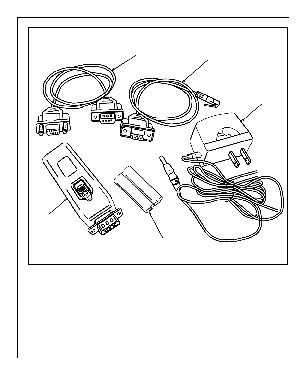
Figure 1. Bluetooth Programming Adapter Components
DB9 TO DB9 CABLE
FOR STANVISION
DB9 TO RJ12 CABLE
FOR MC521
AC CHARGER
BLUETOOTH
PROGRAMMING
ADAPTER
NiMH BATTERIES
204063
Rev. B, 11/23/10
© 2010, THE STANLEY WORKS. ALL RIGHTS RESERVED. 2 of 22
BLU001
Page 4
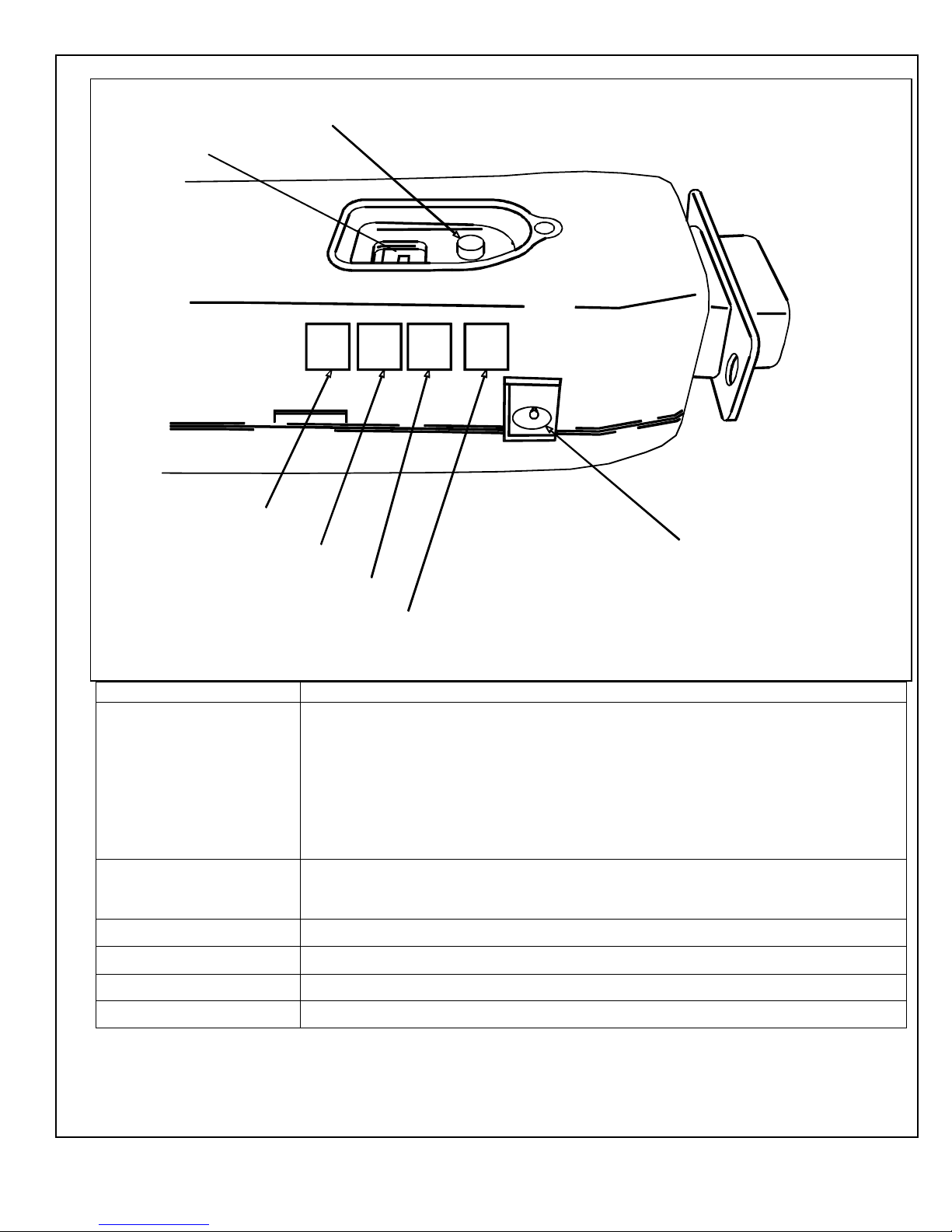
DIP SWITCHES
Figure 2. Bluetooth Programming Adapter Controls and Indicators
POWER BUTTON
GREEN LED
YELLOW LED
BLUE LED
RED LED
CHARGER INPUT
BLU003
Control/Indicator Function
Red Power Button
Controls power to the Bluetooth Programming Adapter.
Pressing and holding the red power button until the blue and green LEDs flash back
and forth several times then releasing the button turns power on. This is indicated by
the green LED flashing two times per second.
Pressing and holding the red power button until the blue and green LEDs flash back
and forth several times then releasing the button turns power off. This is indicated by
the blue and green LED remaining off.
Green LED Indicates wireless connection status. Flashes two times per second when in standby.
(Power will time out when in standby for more than three minutes.) Illuminates
steady when connected.
Yellow LED Indicates data transfer status. Blinks while data is transferring.
Blue LED Indicates battery life status. Flashes once every two seconds when battery is low.
Red LED
Charger Input Socket
Charge indicator. Turns on when batteries are charging.
Allows connection of AC charger.
204063
Rev. B, 11/23/10
© 2010, THE STANLEY WORKS. ALL RIGHTS RESERVED. 3 of 22
Page 5

1.2 Applicability
This manual is applicable to the Stanley Bluetooth Programming Adapter. This device can be
used for tune-in of an MC521 controller or StanVision sensor controller.
2. PREREQUISITES
2.1 All four DIP switches have been set in the down position.
2.2 The area has been cleared of all obstructions.
2.3 Attachment 1 has been reviewed for the following:
Definitions of the terms used in this procedure
A listing of the documents, special tools and equipment, materials, and consumables used in
this procedure.
3. PRECAUTIONS
3.1 AAA alkaline batteries can be used to power this unit. However, standard alkaline batteries are
not
designed to be recharged and should never be placed in any battery charger. Attempting to
charge alkaline batteries will significantly increase the likelihood for battery leakage. Only use
the wall charger with NiMH-type rechargeable batteries.
3.2 If while trying to make a connection to the dongle a message indicates that a connection could not
be made, verify that power is on and that the green LED is flashing two times per second. Then,
try to make the connection again. (This may need to be repeated a couple of times.) If connection
is lost or out of range, turn power to the dongle off, close the application on the handheld device,
and try again.
204063
Rev. B, 11/23/10
© 2010, THE STANLEY WORKS. ALL RIGHTS RESERVED. 4 of 22
Page 6

4. INSTRUCTIONS
WARNING
To prevent injury to personnel and damage to equipment, never recharge AAA alkaline batteries with the
wall charger. Only use the wall charger with NiMH-type rechargeable batteries.
NOTE
The batteries should be charged before using.
4.1 Removing, Installing, and Charging, and the Bluetooth Batteries
4.1.1 Refer to Figure 2, and REMOVE the batteries from the Bluetooth Programming
Adapter as follows:
a. PUSH the tab on the end of the unit opposite the DB9 connector.
b. SWING the cover up until it releases.
c. REMOVE the two batteries.
4.1.2 INSTALL the batteries into the Bluetooth Programming Adapter as follows:
a. OBSERVE the correct polarity of the batteries and dongle, and INSTALL the two
batteries into the unit.
b. SNAP the cover into place.
4.1.3 CHARGE the batteries as follows:
a. INSERT the DC connector from the charger into the socket located on the side of
the Bluetooth Programming Adapter.
b. PLUG the charger into the wall outlet. The red LED shall illuminate while the unit
is charging.
4.2 Powering the Bluetooth Programming Adapter On and Off
4.2.1 POWER the Bluetooth Programming Adapter on as follows:
a. PRESS and HOLD the red power button until the blue and green LEDs flash back
and forth several times.
b. RELEASE the power button. The green LED shall flash.
4.2.2 POWER the Bluetooth Programming Adapter off as follows:
a. PRESS and HOLD the red power button until the blue and green LEDs flash back
and forth several times.
b. RELEASE the power button. The blue and green LED shall turn off.
204063
Rev. B, 11/23/10
© 2010, THE STANLEY WORKS. ALL RIGHTS RESERVED. 5 of 22
Page 7
4.3 Pairing the Bluetooth Programming Adapter to a Palm Handheld Device Using the MC521
Toolbox
NOTE
It sometimes takes more than one press to activate the Bluetooth selections.
Step 1: Using the MC521 cable, connect the DB9F
connector to the Bluetooth Programming Adapter.
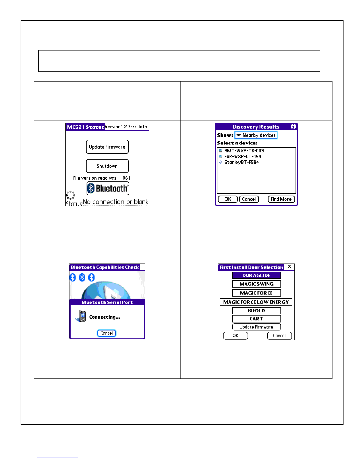
Step 3: Turn on power to the Bluetooth Programming
Adapter. Run the MC521Toolbox application. Select
the Bluetooth button. The Bluetooth Discovery
Results screen shall be displayed.
Step 2: CONNECT the RJ11M connector to Com1 of
the MC521 controller and make sure that the cable and
Bluetooth Programming Adapter are not in the path of
any moving door parts.
Step 4: On the Bluetooth Discovery Results screen,
select Nearby Devices from the Show dropdown list.
The Bluetooth dongle shall be listed as StanleyBTXXXX, where XXXX are the last four digits of the
serial number on the unit label. Select the Bluetooth and
click OK.
Step 5: The following shall occur: The Bluetooth
Capabilities Check screen shall be displayed. Then,
the Bluetooth Serial Port Connecting… screen shall
be displayed. Then, a series of three small Bluetooth
logos shall be displayed.
204063
Rev. B, 11/23/10
© 2010, THE STANLEY WORKS. ALL RIGHTS RESERVED. 6 of 22
Step 6: The First Install Door Selection screen shall
be displayed.
Page 8

Step 7: Or, the Main Selection screen shall be
displayed, depending on whether the controller has
been set up with an FIS or not. The green LED on the
Bluetooth Programming Adapter shall illuminate
steady indicating that it has a connection with the
handheld device. At this point all functions are
available and operate the same as when the cable is
used. When the wireless link is connected and the
green LED on the unit illuminates steady the power
remains on and does not time out.
Step 8: Refer to one of the following as applicable and
tune-in door:
Stanley Access Technologies document No.
204003, “MC521 Controller Installation and
Operation Manual”
Stanley Access Technologies document No.
204027, “Magic-Swing, Magic-Force, and
Bifold MC521 Control Box Quick-Reference Guide
4.4 Pairing the Bluetooth Programming Adapter to a Palm Handheld Device Using the M40
Express Setup
Step 1: Using the Stanvision cable, connect the DB9F
connector to the Bluetooth Programming Adapter.
Step 2: CONNECT the DB9M connector to the
Stanvision Visual Sensor Controller (VSC). Make sure
that the cable and Bluetooth Programming Adapter are
not in the path of any moving door parts.
Step 3: Turn on power to the Bluetooth dongle. Click
on the M40 EXPRESS SETUP icon and run the M40
EXPRESS application. Select the Connection button.
The StanVision Connection Choices screen shall be
Step 4: On the StanVision Connection Choices
screen, select the Bluetooth button. The Bluetooth
Discovery Results screen shall be displayed.
displayed.
204063
Rev. B, 11/23/10
© 2010, THE STANLEY WORKS. ALL RIGHTS RESERVED. 7 of 22
Page 9

Step 5: On the Bluetooth Discovery Results screen,
select Nearby Devices from the Show dropdown list.
The Bluetooth Programming Adapter shall be listed
as StanleyBT-XXXX, where XXXX are the last four
digits of the serial number on the unit label. Select the
Bluetooth and click OK.
Step 7: The M40 Express Setup screen shall be
displayed. At the top of the screen, the Bluetooth icon
and + sign shall indicate a connection. The green LED
on the dongle shall illuminate steady indicating that it
has a connection with the handheld device. At this
point all functions are available and operate the same
as when the cable is used. When the wireless link is
connected and the green LED on the unit illuminates
steady the power remains on and does not time out.
Step 6: The following shall occur: The Bluetooth
Capabilities Check screen shall be displayed. Then, the
Bluetooth Serial Port Connecting… screen shall be
displayed. Then, a series of three small Bluetooth logos
shall be displayed.
Step 8: Refer to Stanley Access Technologies
document No. 203975, “StanVision Sensor
Installation and Operating Instructions QuickReference Guide,” and tune-in door.
204063
Rev. B, 11/23/10
© 2010, THE STANLEY WORKS. ALL RIGHTS RESERVED. 8 of 22
Page 10

4.5 Pairing the HTC Touch Pro 2 with a Serialio Bluetooth Dongle
Step 1: Starting at the Home screen, TAP the
Windows logo at the top left of the screen. The
Windows home screen shall be displayed.
Step 2: TAP the Settings logo. The Settings screen
shall be displayed.
Step 3: TAP the Wireless controls selection. The
Wireless controls screen shall be displayed.
204063
Rev. B, 11/23/10
© 2010, THE STANLEY WORKS. ALL RIGHTS RESERVED. 9 of 22
Step 4: TAP the Bluetooth switch on the right. The
Bluetooth shall turn on. TAP the Bluetooth logo on the
left. The Bluetooth Settings screen shall be displayed.
Page 11

Step 5: Turn on the power of the Bluetooth dongle.
TAP the first tab on the left. TAP the Add a device
selection. The Device Selection screen shall be
displayed.
Step 6: TAP the Bluetooth dongle selection. (Use the
window scroll bar if necessary.) The Passkey screen
shall be displayed.
NOTE: The Bluetooth dongle will show in the list as
StanleyBT-####, where #### is the last four digits on
the Bluetooth device label. (Note: This is a hexadecimal
string and may contain 0-9 and A-F.) Also, be sure the
power is turned on and it is in range.
Step 7: On the Passkey screen ENTER 1234, and
TAP OK at the bottom left of the screen.
204063
Rev. B, 11/23/10
© 2010, THE STANLEY WORKS. ALL RIGHTS RESERVED. 10 of 22
Step 8: TAP Done at the bottom left of the screen.
Page 12

Step 9: TAP Continue at the bottom left of the
screen.
Step 10: TAP the SPP selection below the Bluetooth
dongle listed. The system shall test the connection and
display the connection status.
Step 11: OBSERVE the connection status at the
bottom of the screen. The green LED on the dongle
shall illuminate steady indicating that it is connected
to the device.
204063
Rev. B, 11/23/10
© 2010, THE STANLEY WORKS. ALL RIGHTS RESERVED. 11 of 22
Step 12: TAP the Disconnect selection at the bottom
left of the screen.
Page 13

Step 13: TAP the Windows logo at the top left of the
screen. The Windows home screen shall be displayed.
Step 15: You are now ready to use the Bluetooth
dongle to connect to the MC521 and StanVision VSC
controllers using the Stanley Windows Mobile
applications.
Step 14: TAP the Home logo. The Home screen shall
be displayed.
204063
Rev. B, 11/23/10
© 2010, THE STANLEY WORKS. ALL RIGHTS RESERVED. 12 of 22
Page 14

4.6 Pairing a Motorola ES400 with a Serialio Bluetooth Dongle
Step 1: Starting at the Home screen, TAP the
Windows logo at the bottom left of the screen. The
Windows home screen shall be displayed.
Step 2: TAP the Settings logo. The Settings screen
shall be displayed.
Step 3: TAP the Bluetooth logo. The Devices screen
shall be displayed.
204063
Rev. B, 11/23/10
© 2010, THE STANLEY WORKS. ALL RIGHTS RESERVED. 13 of 22
Step 4: On the Bluetooth dongle, SET the power to on.
On the Bluetooth Devices tab, TAP the Add new
device. The Device Selection screen shall be displayed.
Page 15

Step 5: TAP the Bluetooth dongle selection.
(Use the window scroll bar if necessary.) TAP Next at
the bottom right of the screen. The Passkey screen
shall be displayed.
NOTE: The Bluetooth dongle will show in the list as
StanleyBT-####, where #### is the last four digits on
the Bluetooth device label. (Note: This is a
hexadecimal string and may contain 0-9 and A-F.)
Also, be sure the power is turned on and it is in range.
Step 6: On the Passkey page, ENTER 1234, and TAP
Next at the bottom right of the screen. The Device
Added indication shall be displayed.
Step 7: TAP Done at the bottom left of the screen.
204063
Rev. B, 11/23/10
© 2010, THE STANLEY WORKS. ALL RIGHTS RESERVED. 14 of 22
Step 8: TAP the COM Ports tab at the top left of the
screen.
Page 16

Step 9: TAP the New Outgoing Port selection.
Step 10: TAP Finish at the bottom right of the screen.
Step 11: TAP OK at the bottom right of the screen.
The Settings screen shall be displayed.
204063
Rev. B, 11/23/10
© 2010, THE STANLEY WORKS. ALL RIGHTS RESERVED. 15 of 22
Step 12: Tap X at the bottom right of the screen. The
Home screen shall be displayed.
Page 17

Step 13: You are now ready to use the Bluetooth
dongle to connect to the MC521 and StanVision VSC
controllers using the Stanley Windows Mobile
applications.
204063
Rev. B, 11/23/10
© 2010, THE STANLEY WORKS. ALL RIGHTS RESERVED. 16 of 22
Page 18

4.7 Pairing an HP iPAQ 211 with a Serialio Bluetooth Dongle
Step 1: Starting at the Home screen, TAP the iPAQ
Wireless icon on the top left of the screen. The iPAQ
Wireless screen shall be displayed.
Step 2: TAP the Status: Off selection. The Status
indication shall change to ON.
Step 3: TAP the Bluetooth Connections selection.
The Devices screen shall be displayed.
204063
Rev. B, 11/23/10
© 2010, THE STANLEY WORKS. ALL RIGHTS RESERVED. 17 of 22
Step 4: TAP the New selection at the bottom left of the
screen. The Connection Wizard screen shall be
displayed.
Page 19

Step 5: On the Bluetooth dongle, SET the power to
on.
On the connection Wizard screen, TAP the Explore a
Bluetooth device selection.
Step 6: TAP the Bluetooth dongle selection.
(Use the window scroll bar if necessary.) The
Retrieving services prompt shall be displayed.
NOTE: The Bluetooth dongle will show in the list as
StanleyBT-####, where #### is the last four digits on
the Bluetooth device label. (Note: This is a hexadecimal
string and may contain 0-9 and A-F.) Also, be sure the
power is turned on and it is in range.
Step 7: After the service has been retrieved,
OBSERVE that the SPP selection is displayed.
204063
Rev. B, 11/23/10
© 2010, THE STANLEY WORKS. ALL RIGHTS RESERVED. 18 of 22
Step 8: TAP the SPP selection. Then TAP the Next
selection at the bottom right of the screen. The
Shortcuts created message shall be displayed.
Page 20

Step 9: TAP the Finish selection at the bottom right
of the screen.
Step 10: TAP and HOLD the StanleyBT-XXXX icon
until the pop-up menu appears.
Step 11: TAP the Connect selection in the pop-up
menu. The Connecting... prompt shall be displayed.
204063
Rev. B, 11/23/10
© 2010, THE STANLEY WORKS. ALL RIGHTS RESERVED. 19 of 22
Step 12: OBSERVE that the Connecting... prompt and
then the Bluetooth Authentication pop-up appears.
Page 21

Step 13: ENTER the PIN code 1234, and TAP OK. Step 14: OBSERVE that the connector icon shows
green arrows, indicating that the connection is made.
Also OBSERVE that the green LED on the dongle
illuminates steady, indicating that it is connected to the
device.
Step 15: TAP and HOLD the StanleyBT-XXXX icon
selection until the pop-up menu appears, then TAP
Disconnect.
204063
Rev. B, 11/23/10
© 2010, THE STANLEY WORKS. ALL RIGHTS RESERVED. 20 of 22
Step 16: TAP the X icon at the top right of the screen
or the OK button at the bottom of the device. The Start
screen shall be displayed.
Page 22

Step 17: You are now ready to use the Bluetooth
dongle to connect to the MC521 and StanVision VSC
controllers using the Stanley Windows Mobile
applications.
204063
Rev. B, 11/23/10
© 2010, THE STANLEY WORKS. ALL RIGHTS RESERVED. 21 of 22
Page 23

Attachment 1
Documents, Definitions, Special Tools, Equipment, Materials, and Consumables
(Sheet 1 of 1)
Documents
Stanley Access Technologies document No. 204003, “MC521 Controller Installation and Operation
Manual”
Stanley Access Technologies document No. 204027, “Magic-Swing, Magic-Force, and Bifold
MC521 Control Box Quick-Reference Guide”
Stanley Access Technologies document No. 203975, “StanVision Sensor Installation and Operating
Definitions
Instructions Quick-Reference Guide”
Dongle: A small wireless device that plugs into the Stanley controllers. The dongle serves as a
wireless connection to enable the use of the Stanley Palm operating system and Windows Mobile
applications.
LED: Light-emitting diode
NiMH: Nickel-metal hydride battery
VSC: Visual sensor controller
Special Tools and Equipment (including, but not limited to)
None
Materials (including, but not limited to)
None
Consumables (including, but not limited to)
None
204063
Rev. B, 11/23/10
© 2010, THE STANLEY WORKS. ALL RIGHTS RESERVED. 22 of 22
 Loading...