

Page 1

Program Controller SE-707
© 2018 by STANGE Elektronik GmbH
Subject to technical modifica tions
1
Operating Manual
Program Controller
SE-707
Documentation: October 2018
Page 2

Program Controller SE-707
© 2018 by STANGE Elektronik GmbH
2 Subject to technic al modifications
Table of Contents
1 GENERAL ........................................................................................................................................................................... 5
1.1 INFORMATION ABOUT THE OPERATING MANUAL ...................................................................................................................... 5
1.2 SYMBOL DECLARATION ...................................................................................................................................................... 5
1.3 EU-CONFORMITY ............................................................................................................................................................ 6
1.4 LIABILITY AND WARRANTY .................................................................................................................................................. 7
1.5 COPYRIGHT PROTECTION .................................................................................................................................................... 7
2 SAFETY .............................................................................................................................................................................. 8
2.1 INTENDED USE ................................................................................................................................................................. 8
2.2 ELECTROMAGNETIC COMPATIBILITY (EMC) ............................................................................................................................ 8
2.3 EMC SAFEGUARDING ........................................................................................................................................................ 8
2.4 GROUNDING OF INACTIVE METAL PARTS ................................................................................................................................. 9
2.5 PE CONNECTION .............................................................................................................................................................. 9
2.6 UNEARTHED OPERATION .................................................................................................................................................... 9
2.7 RESPON SIBILITY OF THE OPERATOR ....................................................................................................................................... 9
2.8 OPERATING PERSONAL .....................................................................................................................................................10
2.9 MAINTENANCE ...............................................................................................................................................................10
2.10 CLEANING THE FR ONT PANEL ............................................................................................................................................10
2.11 REPAIR S......................................................................................................................................................................10
2.12 MANUFACTURER-ADDRESS .............................................................................................................................................11
2.13 TECHNIC AL SUPPORT .....................................................................................................................................................11
2.14 DISPOSAL ....................................................................................................................................................................11
3 TRANSPORT, PACKING AND STORAGE ............................................................................................................................12
3.1 TRANSPORT INSPECTION ...................................................................................................................................................12
3.2 PACKING .......................................................................................................................................................................12
3.3 STORAGE ......................................................................................................................................................................12
4 TECHNICAL DATA .............................................................................................................................................................13
4.1 HARDWARE CHARACTERISTICS ............................................................................................................................................13
4.2 SOFTWARE SPECIFICATIONS ...............................................................................................................................................15
4.3 FUNCTION BASIC DATA .....................................................................................................................................................16
5 INSTALLATION OF THE INDUSTRIAL CONTROL .................................................................................................................18
5.1 GUIDEL INES FOR THE INSTALLATION OF THE SE-707 ................................................................................................................18
5.2 GENERAL MOUNTING INSTRUCTIONS ....................................................................................................................................18
5.3 INSTALLATION DIMENSION .................................................................................................................................................19
5.4 INSTALLATION DEPTH .......................................................................................................................................................20
5.5 FRONT PANEL INSTALLATION ..............................................................................................................................................21
6 START-UP .........................................................................................................................................................................22
6.1 GUIDEL INES FOR GROUNDING AND WIRING ...........................................................................................................................22
6.2 OVERVIEW OF THE CONNECTIONS ........................................................................................................................................23
6.2.1 Function of the LED's at the back of the device .....................................................................................................24
6.2.2 Turn-switch for PLC operating mode selection......................................................................................................25
6.2.3 System Watchdog ...............................................................................................................................................25
6.2.3.1 General ............................................................................................................................................................25
6.2.3.2 Mode of operation ...........................................................................................................................................25
6.2.3.3 System logger entry ..........................................................................................................................................26
6.2.4 The alarm relay ...................................................................................................................................................26
6.2.4.1 General ............................................................................................................................................................26
6.2.4.2 Mode of operation ...........................................................................................................................................26
6.3 MOUNTING / DISMOUNTING THE SD CARD ............................................................................................................................27
6.4 CONNECTING THE POWER SUPPLY........................................................................................................................................28
6.5 PACKAGING THE CAN CABLE WITH SHIELD CONNECTION ...........................................................................................................29
6.6 CONNECTING THE PROGRAMMING INTERFACE RJ45 ................................................................................................................30
Page 3

Program Controller SE-707
© 2018 by STANGE Elektronik GmbH
Subject to technical modifica tions
3
6.7 CONNECTION CAN ......................................................................................................................................................... 31
6.8 CONNECTION OF THE ALARM SOCKET ................................................................................................................................... 33
6.9 CONNECTION OF THE PROFIBUS-DP-SLAVE INTERFACE (OPTION) ............................................................................................ 33
6.10 CONNECTION OF THE PROFINET IO DEVICE (SLAVE) INTERFACE (OPTION) ................................................................................ 37
6.11 CONNECTION OF A PC WITH THE SE-707 ........................................................................................................................... 39
6.11.1 Cabling ............................................................................................................................................................. 39
6.12 SETTINGS OF THE PC FOR ETHERNET COMMUNICATION .......................................................................................................... 39
6.12.1 Separation of automation network and company/office network ...................................................................... 39
6.12.2 Length of the network line (segment length) ..................................................................................................... 40
6.12.3 Requirements ................................................................................................................................................... 40
6.12.4 Settings Windows 7/10 ..................................................................................................................................... 40
6.12.5 Settings of the IP-address in the device ............................................................................................................. 41
7 OPERATION ..................................................................................................................................................................... 42
7.1 START-UP B EHAVIOUR ..................................................................................................................................................... 42
7.2 SHUTDO WN BEHAVIOUR .................................................................................................................................................. 42
7.3 START-UP B EHAVIOUR / STARTING ...................................................................................................................................... 43
8 OPERATING DIALOGUE OF THE CONTROL SOFTWARE ..................................................................................................... 44
8.1 OPERATION .................................................................................................................................................................. 44
8.1.1 Start screen ........................................................................................................................................................ 45
8.1.2 Programmer ....................................................................................................................................................... 45
8.1.3 Manual operation for set value and tracks (”Manual”) ........................................................................................ 46
8.1.4 Program curve .................................................................................................................................................... 46
8.1.5 Program jump .................................................................................................................................................... 47
8.1.6 Automatic Program Start .................................................................................................................................... 47
8.1.7 Program change in actual segment ..................................................................................................................... 48
8.1.8 Editing of the operating program ........................................................................................................................ 48
8.1.9 Controller ........................................................................................................................................................... 49
8.1.10 Control Zone Detail View .................................................................................................................................. 49
8.1.11 PID Parameter .................................................................................................................................................. 50
8.1.12 Control zone tolerance values / limit values....................................................................................................... 51
8.1.13 Plant overview .................................................................................................................................................. 51
8.1.14 Alarms .............................................................................................................................................................. 52
8.1.15 Alarm history .................................................................................................................................................... 53
8.1.16 Process data actual values ................................................................................................................................ 53
8.1.17 Process data limit values................................................................................................................................... 54
8.1.18 Process data tolerance values ........................................................................................................................... 54
8.1.19 Process data formula value ............................................................................................................................... 54
8.1.20 Operating-Hours Meter (Option) ....................................................................................................................... 55
8.1.21 Data Logger (Option) ........................................................................................................................................ 55
8.1.22 Logger Graph (Option) ...................................................................................................................................... 56
8.1.23 Logger Header (Option) .................................................................................................................................... 57
8.1.24 Program start with data logger (Option) ........................................................................................................... 57
8.1.25 Configuration ................................................................................................................................................... 57
8.1.26 Login ................................................................................................................................................................ 58
8.1.27 Login Level Authorisation .................................................................................................................................. 59
8.2 PROGRAM .................................................................................................................................................................... 61
8.2.1 Program overview .............................................................................................................................................. 61
8.2.2 Creating programs.............................................................................................................................................. 61
8.2.3 Programming segments...................................................................................................................................... 62
8.2.4 Copy programs ................................................................................................................................................... 62
8.2.5 Delete programs ................................................................................................................................................. 63
8.2.6 Load programs to the operating mode ................................................................................................................ 63
8.2.7 Sort programs .................................................................................................................................................... 63
8.2.8 Store and load program list ................................................................................................................................ 64
8.2.9 Loops ................................................................................................................................................................. 65
8.3 CONFIGURATION ............................................................................................................................................................ 66
8.3.1 Standard Settings ............................................................................................................................................... 67
Page 4

Program Controller SE-707
© 2018 by STANGE Elektronik GmbH
4 Subject to technic al modifications
8.3.1.1 Station Name.................................................................................................................................................................. 67
8.3.1.2 Display screen ................................................................................................................................................................ 67
8.3.1.3 Host Interface ................................................................................................................................................................. 68
8.3.1.4 Siemens Modbus Connection (Option) ............................................................................................................................ 69
8.3.1.5 Programmer ................................................................................................................................................................... 69
8.3.1.6 User interface ................................................................................................................................................................. 70
8.3.2 Hardware ............................................................................................................................................................71
8.3.2.1 CAN Inputs/Outputs ....................................................................................................................................................... 71
8.3.2.2 Hardware Options .......................................................................................................................................................... 72
8.3.2.2.1 Profinet IO Device Interface ......................................................................................................................................... 73
8.3.2.2.2 Profibus-DP Slave interface .......................................................................................................................................... 76
8.3.2.2.3 PROFIBUS Function Description .................................................................................................................................... 78
8.3.3 Functions ............................................................................................................................................................86
8.3.3.1 Digital and analogue inputs/outputs ............................................................................................................................... 86
8.3.3.2 Actual values .................................................................................................................................................................. 87
8.3.3.3 Analogue outputs ........................................................................................................................................................... 94
8.3.3.4 Free linearization curves ................................................................................................................................................. 96
8.3.3.5 Set values ....................................................................................................................................................................... 98
8.3.3.6 Control zones ............................................................................................................................................................... 101
8.3.3.7 Tolerances .................................................................................................................................................................... 122
8.3.3.8 Limit values .................................................................................................................................................................. 125
8.3.3.9 Alarm monitoring ......................................................................................................................................................... 128
8.3.3.10 Formula / constants .................................................................................................................................................... 132
8.3.3.11 PLC Statement List ...................................................................................................................................................... 134
8.3.3.12 Analogue Variables ..................................................................................................................................................... 140
8.3.3.13 Digital tracks ............................................................................................................................................................... 142
8.3.3.14 Process steps .............................................................................................................................................................. 143
8.3.3.15 Analogue multiplexers ................................................................................................................................................ 144
8.3.3.16 BCD/BIN Decoders ...................................................................................................................................................... 145
8.3.4 Special Functions ............................................................................................................................................... 148
8.3.4.1 C-Level (Option) ............................................................................................................................................................ 148
8.3.4.2 Humidity Calculation..................................................................................................................................................... 152
8.3.4.3 Data Logger (Option) .................................................................................................................................................... 153
8.3.4.4 Operating-Hours Meter (Option) ................................................................................................................................... 163
8.3.5 User Administration .......................................................................................................................................... 164
8.3.5.1 User ............................................................................................................................................................................. 164
8.3.5.2 User Groups ................................................................................................................................................................. 165
8.3.5.3 Automatic user login ..................................................................................................................................................... 167
8.3.5.4 User Profile Modbus ..................................................................................................................................................... 167
8.3.6 Settings ............................................................................................................................................................. 168
8.3.6.1 Date / Time .................................................................................................................................................................. 168
8.3.6.2 Language dialogue ........................................................................................................................................................ 169
8.3.6.3 Program Graph Pen Settings ......................................................................................................................................... 169
8.3.7 Administrate configuration ................................................................................................................................ 170
8.3.7.1 Load configuration ........................................................................................................................................................ 170
8.3.7.2 Save configuration ........................................................................................................................................................ 170
8.3.7.3 Import configuration from SE-5xx or SE-4xx device ........................................................................................................ 171
8.3.7.4 Import licence file ......................................................................................................................................................... 171
8.3.7.5 Reset configuration/programs (general reset) ............................................................................................................... 171
8.3.8 Update Firmware and/or license update ............................................................................................................ 172
8.3.8.1 Requirements ............................................................................................................................................................... 172
8.3.8.2 Execution of the update process ................................................................................................................................... 172
8.3.9 Hardware test ................................................................................................................................................... 173
8.3.9.1 Device information ....................................................................................................................................................... 173
8.3.9.2 Software information.................................................................................................................................................... 173
8.3.9.3 Licence information ...................................................................................................................................................... 174
8.3.9.4 Device health................................................................................................................................................................ 174
8.3.9.5 Digital In-/Outputs ........................................................................................................................................................ 174
8.3.9.6 Save diagnosis data....................................................................................................................................................... 174
INDEX ................................................................................................................................................................................. 175
Page 5
Program Controller SE-707
© 2018 by STANGE Elektronik GmbH
Subject to technical modifica tions
5
1 General
1.1 Information about the operating manual
This operating manual shall put the user into the position to install, put into operation, administrate and service the device
properly.
Read and understand the operating manual completely, in particular the chapter security, before the beginning of the
installation work! Comply with the operating manual, in particular the safety references as well as the regulations for the
prevention of industrial accidents, valid for the area of application, absolutely.
Always pass the device together with the operating manual to a third party.
1.2 Symbol declaration
Important safety-relevant references are characterized by symbols in this manual. Comply with the references absolutely, in
order to avoid accidents, damages to persons and physical damage.
WARNING!
This symbol marks dangers which result in impairment of health, injuries, lasting physical injury or to
death, as well as substantial property damage.
Keep the displayed references to the operational safety absolute exactly and behave in these cases
particular carefully.
WARNING! Danger by electric current!
This symbol makes attentive to dangerous situations by electric current. In case of non-observance of
the safety references the danger of heavy injuries or death exists like substantial damage to property.
The executed work may be implemented only by an instructed electrical specialist.
ATTENTION ! Consider ESD electronic protective measures!
Electrostatic unloading may destroy electronic components.
ATTENTION !
This symbol marks references, whose non-observance can result in damages, malfunctioning and/or loss
of the device.
Note
This symbol emphasizes hints and information, which are to be considered for an efficient and trouble
free operation of the device.
Page 6

Program Controller SE-707
© 2018 by STANGE Elektronik GmbH
6 Subject to technic al modifications
1.3 EU-Conformity
We, the company
Gutenbergstr. 3
D-51645 Gummersbach
declare under sole responsibility, that the product
Name: Program Controller
Type: SE-707
fulfils the requirements of the standard
EN 61000-6-4:2007+A1:2011 Emission
EN 61000-6-2:2005 Interference resistance
and therefore corresponds to the regulations of the EU-Directive 2014/30/EU (electromagnetic compatibility).
Gummersbach, 2018-06-25 P. Jaspert (Managing Director)
_________________________________ _________________________________
Place and Date of Issue Name, authorized Signature
The device was tested in a typical situation.
If modifications are made without our agreement this declaration loses its validity.
The device does not fall into the range of application of the low-voltage directive EEC 73/23/EEC (electrical equipment for the
use within certain voltage limits (low-voltage directive); changed by 93/68/EEC)
(This declaration follows closely to EN 45 014)
Page 7
Program Controller SE-707
© 2018 by STANGE Elektronik GmbH
Subject to technical modifica tions
7
1.4 Liability and warranty
All specifications and notes in this manual were arranged with consideration of the valid regulations, the current engineering
level of development as well as our realizations and experiences of many years.
The translation of the manual was likewise provided after best knowledge. We cannot take over a liability for translation
errors however. Considerably applies the provided German version of this manual.
The actual scope of supply can deviate with special equipment, the demands of additional order options or due to newest
technical changes possibly from the explanations and graphic representations described here. Please contact the
manufacturer if you have questions.
Note!
This manual is to be perused before the beginning of all work on and with the device, in particular before the
start-up! For damage and troubles, which result from the non-observance of the manual, the manufacturer
does not take over liability.
The manual is to be put aside and directly accessible with the device for all persons, who work on or with the device. The
assignment of the manual to third party is not permitted and obligates if necessary to compensation. Further requirements
reserved.
We reserve technical changes at the device in the context of the improvement of the performance characteristics and the
advancement.
1.5 Copyright protection
The manual is to be kept in confidence. It is exclusively intended for persons employed at and with the device. The
assignment of the manual to third party is inadmissible without written agreement of the manufacturer. With requirement
please contact the manufacturer.
Note !
The content-wise specifications, texts, designs, pictures and other representations are copyrighted and are
subject to further industrial property rights. Each abusive utilization is liable to prosecution.
Page 8
Program Controller SE-707
© 2018 by STANGE Elektronik GmbH
8 Subject to technic al modifications
2 Safety
This section gives an overview of all important safety aspects for an optimal protection of the personnel as well as safe and
trouble free operation of the device.
Additionally the individual chapters contain concrete safety references, marked by symbols, for the prevention of direct
dangers. Beyond those pictograms, signboards and markings are present at the device, which have to be kept in constantly
readable condition.
2.1 Intended use
The industrial control exclusively serves for the control of machines and plants, which are build according to the applicable
regulations and equipped with all necessary safety installations.
The operational reliability is ensured only by the intended use of the device.
ATTENTION !
Each use of the device going beyond the intended use and/or different use is forbidden and is
considered as not intended. In particular the use of the device for the control or as replacement of
safeguarding equipment in the sense of the machine directive (98137 EG) is not permitted.
Requirements of any kind against the manufacturer and/or its authorized persons because of damage
on the basis of not intended use of the device are excluded.
For all damages on the basis of not intended use the operator is responsible alone.
Among the intended use also the correct adherence of the operating ranges as well as the installation-,
operation- and cleaning instructions.
2.2 Electromagnetic compatibility (EMC)
Before installing an EMC planning is necessary, even though devices fulfil the EMC requirements. Disturbance sources
(galvanic, inductive and capacitive coupling) as well as radiation coupling come to consideration thereby.
2.3 EMC safeguarding
The following requirements should be kept, in order to safeguard EMC:
• Inactive metal parts must have a correct and extensive grounding.
• Wires and devices have a correct shielding.
• Wiring and line run must be executed correctly.
• The electric equipment is grounded and has a uniform reference potential.
• Special applications need specific EMC measures.
Page 9

Program Controller SE-707
© 2018 by STANGE Elektronik GmbH
Subject to technical modifica tions
9
2.4 Grounding of inactive metal parts
The influence of coupled interferences can be reduced, if all inactive metal parts (switch cabinet, switch cabinet door,
mounting plates, top hat rails etc.) are connected extensive and low-impedance with each other. The uniform reference
potential area results for control elements for this reason.
• In the range of bolted connections the insulating layer must be removed in case of painted eloxadized or isolated
metal parts. It has to be cared for corrosion protection of junctions.
• Connection of all free moving groundable components (cabinet doors, separate mounting plates, etc.) by using short
bonding straps to large surface areas.
• No use of aluminium parts if possible, because the oxidation of aluminium is inappropriate for grounding.
2.5 PE connection
Connect ground and PE connection (protective earth) centrally.
2.6 Unearthed operation
The relevant safety regulations and standards must receive attention in case of unearthed operation.
2.7 Responsibility of the operator
The device may be operated only in technically perfect and safe condition.
Apart from the operational safety notes in this manual are to be considered and kept the generally valid safety regulations
and regulations for the prevention of industrial accidents for the area of application of the device as well as the valid
environmental regulations.
The operator and the personnel authorized by him are responsible for the trouble free operation of the device as well as for
clear definitions over the cognizance during installation, operation, maintenance and cleaning.
The specifications of the manual must be complied completely and without restrictions!
The operator must guarantee beyond that, that
• all further instructions and safety instructions are summarized in an operating instruction in accordance with work
appliance use regulation, which result from the hazard judgement of the employments at the device.
• this manual is integrated into the plant documentation.
• maintenance and inspection intervals are to be kept.
• device, operating equipment and waste products resulting with the manufacturing are disposed environmentally
compatible and in agreement with legal regulations.
Page 10
Program Controller SE-707
© 2018 by STANGE Elektronik GmbH
10 Subject to technic al modifications
2.8 Operating personal
The industrial control may be served only by authorized technical personnel. The service personnel must have been
instructed particularly about arising dangers.
As technical personnel is considered, who can judge the transferred work and recognize possible dangers due to his technical
training, knowledge and experiences as well as knowledge of the relevant regulations.
ATTENTION !
This device may only be used for the applications described in the technical descriptions, and only in connection
with devices or components from other manufacturers which have been approved or recommended by STANGE.
This product can only function correctly and safely if it is transported, stored, set up, and installed correctly, and
operated and maintained as recommended.
2.9 Maintenance
Battery
The storage battery serves for the backup of the real-time clock and the remanent PLC data. With complete charge, the
storage battery has a holding time of approx. 8-10 weeks. In order to avoid data loss, it should be paid attention to the fact
that the device is switched off not longer than this time. With completely empty storage battery a time of 48 hours operation
is needed, until the storage battery has again its full capacity.
Transport
For the transport of the device is to be used excluding the original packaging.
2.10 Cleaning the front panel
The glass of the front panel is treated on the surface in order to permanently minimise light reflections and the adhesion of
finger prints.
A soft, dry cloth is adequate and provides good service for cleaning the front panel.
2.11 Repairs
Repairs at SE-707 may only be made by STANGE Elektronik GmbH. In this case please contact the technical support of
STANGE Elektronik GmbH.
For making changes at the device not described in this document, no liability is accepted.
Page 11

Program Controller SE-707
© 2018 by STANGE Elektronik GmbH
Subject to technical modifica tions
11
2.12 Manufacturer-Address
Manufacturer:
STANGE Elektronik GmbH
Gutenbergstr. 3
51645 Gummersbach
Germany
Fon: +49 (0)2261 - 95790
Fax: +49 (0)2261 - 55212
E-Mail: info@stange-elektronik.de
Homepage: www.stange-elektronik.com
2.13 Technical Support
Support:
Fon: +49 (0)2261 – 957939
Fax: +49 (0)2261 - 55212
E-mail: support@stange-elektronik.de
2.14 Disposal
STANGE units can be recycled. Send back the device delivered free to STANE Elektronik GmbH for disposal. Or contact a
certified electronic waste disposal centre for environmentally acceptable recycling and disposal of your old devices.
Particularly to be considered is:
• The device contains a lithium storage battery.
• The device contains LED background lighting.
Materials:
Housing: Stainless steel
Front frame: Aluminium
Board: 1. quality
Front glass: Float glass ESG (tempered safety glass)
Page 12

Program Controller SE-707
© 2018 by STANGE Elektronik GmbH
12 Subject to technic al modifications
3 Transport, Packing and Storage
3.1 Transport inspection
Examine supply with receipt immediately for completeness and transport damages.
Do not accept delivery or only under reservation with outwardly recognizable transport damage. Note the damage on
transportation document/delivery note of the carrier. Start reclamation.
Reclaim hidden damages immediately after recognizing (at the latest within 8 days (date of receipt)) in writing, because
claims for damages can be made valid only within the valid complaint periods.
3.2 Packing
For the transport of the device is to be used excluding the original packaging.
3.3 Storage
Keep packages up to the assembly locked and considering of the environmental conditions for storage.
Page 13

Program Controller SE-707
© 2018 by STANGE Elektronik GmbH
Subject to technical modifica tions
13
4 Technical data
4.1 Hardware characteristics
Display
Technology
TFT LCD 30.7 cm (12.1”)
Resolution
1280 x 800 pixels (WXGA)
Number of colours
16 Mil. colours
Backlight
LED Front
ESG glass 3 mm
Operation
Type
Capacitive Touch
Dimension
W x H x D
370 x 260 x 106 mm
Weight
approx. 3,7 kg
Protection class
Front
IP 65 (NEMA 12), according to EN 60529
Back
IP 20
Environmental
condition
Climate operation
0 ... 45 °C, 10 ... 90 % relative humidity, non-condensing
Climate storage
-20 ... 60 °C, 10 ... 90 % relative humidity, non-condensing
EMC interference resistance
EN 61000-6-2
Interference radiation
EN 61000-6-3
Power supply
Voltage
24 V DC (18 … 30 V)
Voltage drops
10 ms according EN 61000-6-2
Reverse voltage protection
Yes
Fuse
Solder fuse, 2 A slow-blow
Electrical isolation
Yes Current consumption
Typ. 500 mA at 24 VDC (for 2 min. after power-on 750 mA)
Power consumption
Typ. 20 W
Battery back-up
Battery type
Lithium battery
Data conservation
min. 8-10 weeks
Battery charge
Complete after approx. 48 hours operation
System time
Real-time clock (RTC)
Date/Time
Accuracy
50 ppm (max. 131 seconds deviation per month)
Time levelling
Manual or over network time server
Memory card
SD card
Data logger
Page 14

Program Controller SE-707
© 2018 by STANGE Elektronik GmbH
14 Subject to technic al modifications
Interfaces
Alarm output
Semiconductor relay output, 24V AC/DC, 300 mA,
contact type normally open contact, potential-free
Watchdog output
Semiconductor relay output, 24V AC/DC, 300 mA,
normally closed contact, potential-free
CAN
CANopen fieldbus,
9-pole SubminD connector, electrically isolated
USB 1 and 2
USB connection (female) for external storage medium (USBMemory-Stick)
Ethernet connector
Ethernet 10/100 Mbit/s, RJ45 female connector
Profibus-DP (optional !)
Profibus-DP Slave,
optional interface module,
9-pole SubminD connector, electrically isolated
Processor core
CPU
Freescale™ i.MX 6 ARM
Random access memory
1 GB DRAM
Memory for mains failure safe data
(PLC retain memory)
1 MB SRAM, battery backed
Page 15
Program Controller SE-707
© 2018 by STANGE Elektronik GmbH
Subject to technical modifica tions
15
4.2 Software specifications
Operating system
Windows Embedded Compact 7
PLC PLC with 3200 statements, 128 timers, programmable in STL
Functions
Controller
Up to 20 control zones (depending on stage of extension
)
Programmer
Programmer function with up to 30 set values and 64 control tracks
(depending on stage of extension)
Recipe management
Management of up to 99 recipes, Import/Export possibility over USB
Memory-Stick or STANGE ECS control system
Alarms
Alarm processing with up to 200 alarms and alarm history
(depending on stage of extension)
Data logger (optional!)
Up to 32 data channels (depending on stage of extension)
Operation and
visualization
- Ready-made graphical user interface installation possibility of
customer-specific screen pages and/or unit diagrams (depending on
stage of extension
)
- Administration of 8 operating levels (user profiles)
- Online language switching with Unicode language support
(Russian, Chinese etc.) (depending on stage of extension)
Control system
ECS
SE-707 are designed for STANGE ECS control system connection
"Open" control system interface
In the system the PLC program has priority over the
visualization.
Delays in the visualization may occur
during file transfers (such
as project downloads, FTP, WEB servers), or during
communication with the development system
(e.g. PLC
debugging) as the visualization has the lower priority.
The SD™ storage media (industrial grade) used by STANGE
Elektronik are suitable for the cyclic data recording. Only use the
storage media enclosed to the device.
No formatting of the storage media (loss of the boot sector)!
Page 16

Program Controller SE-707
© 2018 by STANGE Elektronik GmbH
16 Subject to technic al modifications
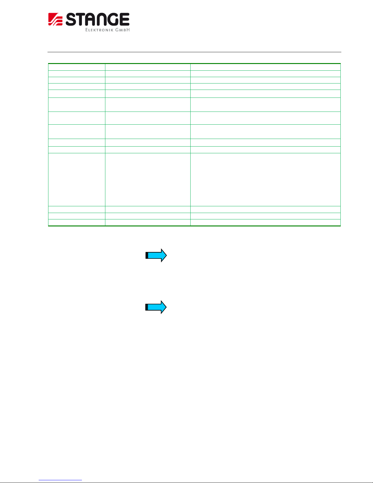
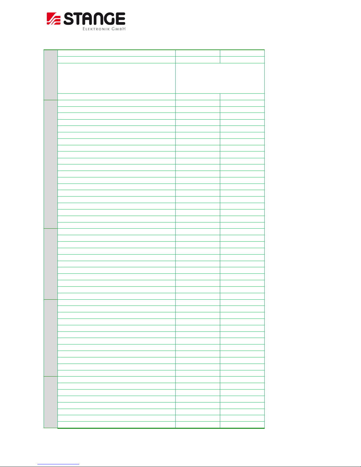
4.3 Function basic data
Function
SE-707/Ext
SE-707/Basic
General
Instrument name
SE-707
SE-707
Instrument code
702001
702000
Instrument code MODB US
72
72
Number of function units (Unit’s)
1
1
Operating dialog languages
4
4
Value descriptions (SV, AV etc.)
24 characters
24 characters
Dimension text
10 characters
10 characters
Number range in case of several values
-9.99999e15 ..
+9.99999e15
-9.99999e15 ..
+9.99999e15
User administration
Number of users total
32
32
Maximum number of logged in users at the same time
10
10
User prof ile
8
8
Login name, maximum length
15 characters
15 characters
Password, maximum length
40 characters
40 characters
User name
40 characters
40 characters
Comment field
1024 characters
1024 characters
I/O’s
Digital inputs
200
64
Digital outputs
200
64
Number of actual values
48
16
Number of average value per actual value
50
50
Number of correction point per actual value
5
5
Free linearization, pair of values
64
64
Number of analogue values
32
16
Maximum CAN node number
15
2
Several individual functions
Number of set values
30
8
Number of digital tracks
64
32
Alarms, external
200
64
Alarms, internal (but only partly used!)
40
40
Alarm history, number of entries
300
150
Alarm text length
100 characters
100 characters
Limit values
40
16
Tolerances
40
16
Formula
20
8
Formula term
31
31
Constants
40
40
Analogue variables
80
80
Number of Modbus data words
200
200
Variables string length
32 characters
32 characters
Analogue value multiplexer
10
5
BCD/BIN decoder
5
5
Page 17
Program Controller SE-707
© 2018 by STANGE Elektronik GmbH
Subject to technical modifica tions
17
Controller
Number of control zones
20
8
PID sets per control zone
8
8
Controller types
2P heating, 2P cooling, 2P-PID heating,
2P-PID heating, PID heating, PID cooling,
PID / PID, PID / 2P, PID / 2P-PID, 2P-PID /
PID, 2P-PID / 2P 2P-PID / 2P-PID, 2P /
PID, 2P / 2P-PID, 2P / 2P, 3 point step
Programmer
Number of time axis
1
1
Program name length
32
32
Set values
30
8
Digital tracks
64
32
Process steps
50
50
Program segments (inclusive start segment)
201
201
Maximum segment time
999:59:59
999:59:59
Maximum program time
1 year
1 year
Loops
8
8
Loop segments
1000000
1000000
Max. number of repetitions
9999
9999
Program archive, number of programs
250
99
Program number range
1..9999
1..9999
Program graphics, number of pins set value
6 6 Program graphics, set value pages
5
2
Program graphics, number of pins digital tracks
6
6
Program graphics, digital tracks pages
11
6
PLC
PLC instructions
3200
3200
Digital input variables
800
800
Digital output variables
800
800
PLC function inputs
1146
1146
PLC function outputs
1615
1615
Flag, not zero voltage safe
256
256
Flag, zero voltage safe
256
256
Comment text length (only monolingual!)
50 characters
50 characters
Data Logger (option)
Number of data loggers
1
1
Number of log values
32
32
Number of header data
20
20 Maximum log data set number
100000
100000
Maximum alarm event number
10000
10000 File number log data directory
200
200
Number of columns log data archive
3 3 Pixel width archive display
380
380
Number of pens graphic display
16
16
Number of pen groups
5
5
Further Functions
Plant picture
Yes, option
Yes, option
Screensaver
Yes
Yes
C-level formula
2, option
1, option
Humidity calculation formula
2
1
Fieldbus interface „netJACK“, Profinet IO DEVICE
Yes, option
Yes, option
Fieldbus interface „netJACK“, Profibus-DP Slave
Yes, option
Yes, option
Page 18
Program Controller SE-707
© 2018 by STANGE Elektronik GmbH
18 Subject to technic al modifications
5 Installation of the industrial control
5.1 Guidelines for the installation of the SE-707
Separate the SE-707 device from heat, high voltage, and electrical noise
As a general rule for laying out the devices of your system, always separate the devices that generate high voltage and high
electrical noise from the low-voltage, logic-type devices such as the SE-707.
When configuring the layout of the SE-707 inside your panel, consider the heat-generating devices and locate the electronictype devices in the cooler areas of your cabinet. Operating any electronic device in a high-temperature environment will
reduce the product life.
Consider also the routing of the wiring for the devices in the panel. Avoid placing low voltage signal wires and
communications cables in the same tray with AC power wiring and high-energy, rapidly-switched DC wiring.
5.2 General mounting instructions
All SE-707 devices are mounted from the front, i.e. in a control panel. They are fastened from the rear with the supplied
fixing frame and 2 securing nuts.
All SE-707 devices can be operated up to a maximum ambient temperature of 45°C. The ambient temperature stated applies
to the area in the direct vicinity of the lower connectors, if the device is mounted vertically with unimpeded air convection
and a maximum operating height of 2000 m above sea level. The cooling slots must always be free in order to ensure the
proper cooling of the system.
The device can be mounted in an enclosure if the ambient temperature is taken into consideration. Provide a wall clearance
of at least 50 mm on all sides of the housing, so that sufficient air circulation is ensured. A minimum clearance of 75 mm
from active elements such as load current supply, transformers etc. must be ensured.
Avoid the exposure of the flat screen to direct sunlight. The radiation from the sun (UV component) reduces the lifespan of
the LCD display.
ATTENTION !
The following must be ensured in order to prevent the device from overheating during operation:
- The cooling slots must always be free in order to ensure the proper cooling of the system.
- Avoid the exposure of the flat screen to direct sunlight.
- The mounting angle must not exceed ± 35° from the vertical
If these conditions cannot be met, the mounting of an external fan is recommended.
Page 19
Program Controller SE-707
© 2018 by STANGE Elektronik GmbH
Subject to technical modifica tions
19
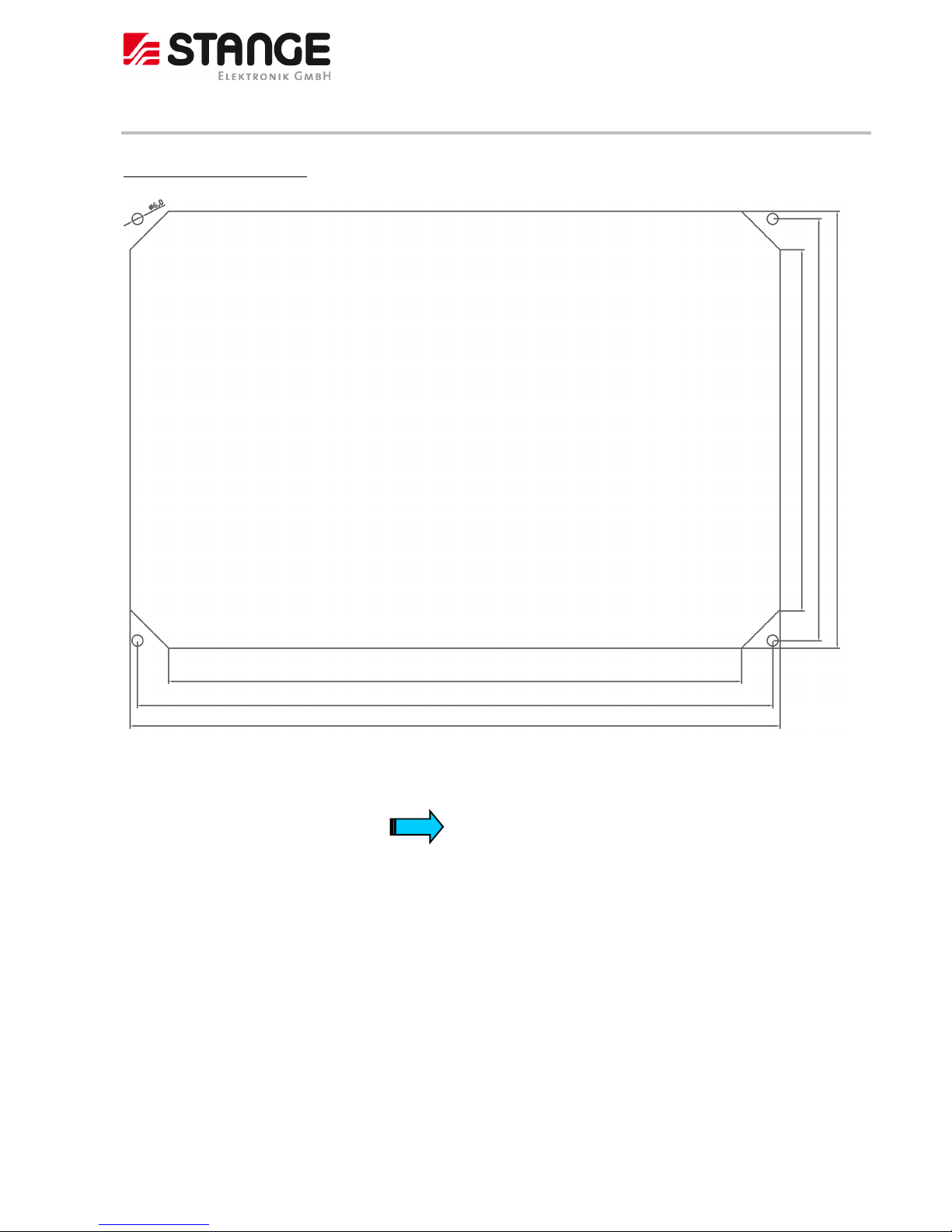
5.3 Installation dimension
Installation dimension SE-707:
The device requires a mounting cut-out of B x H: 354 x 238 mm +/-0,5mm
The thickness of the front panel may not exceed 7 mm.
For better sealing: Use mounting frame rearwards.
196,6
312,0
346,0
354,0
229,8
238,0
Page 20
Program Controller SE-707
© 2018 by STANGE Elektronik GmbH
20 Subject to technic al modifications
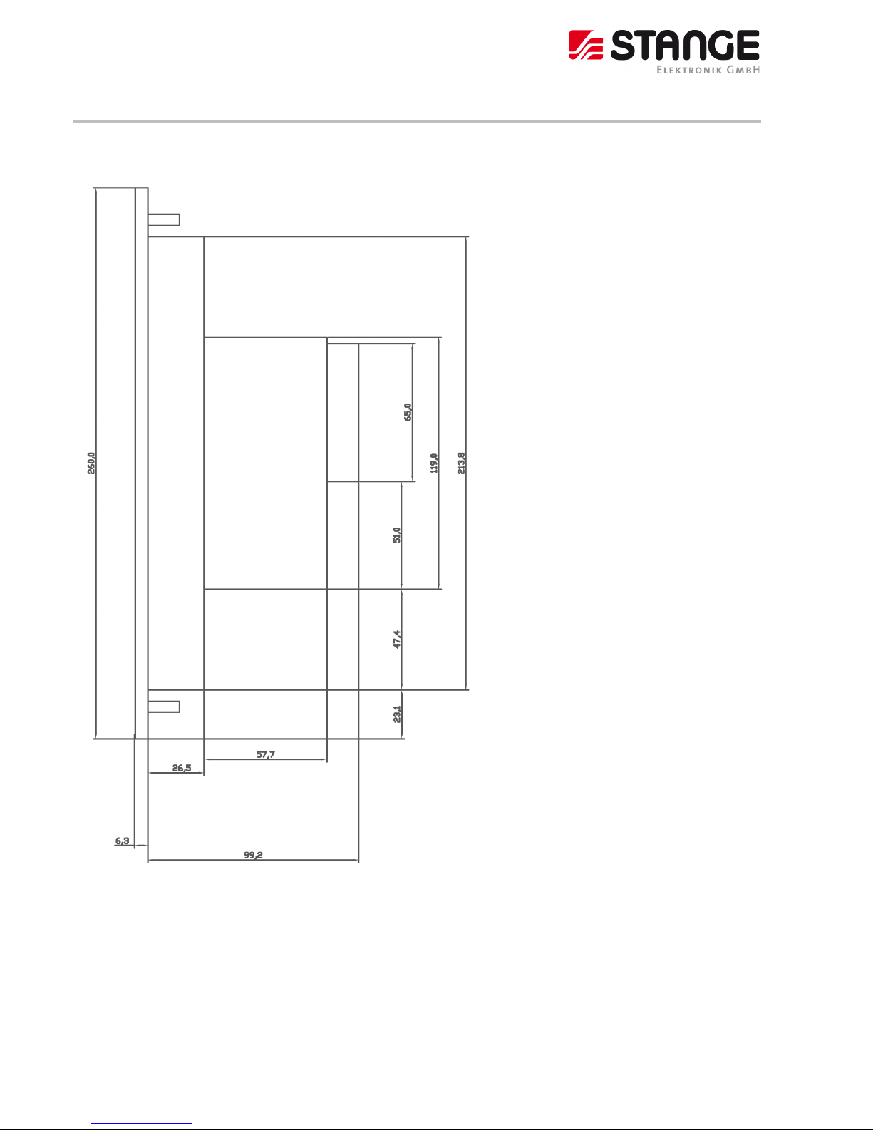
5.4 Installation depth
Installation depth SE-707:
The Installation depth for the SE-707: 99.2 mm.
Length of the mounting clips: 65 mm behind the mounting plate
Page 21
Program Controller SE-707
© 2018 by STANGE Elektronik GmbH
Subject to technical modifica tions
21
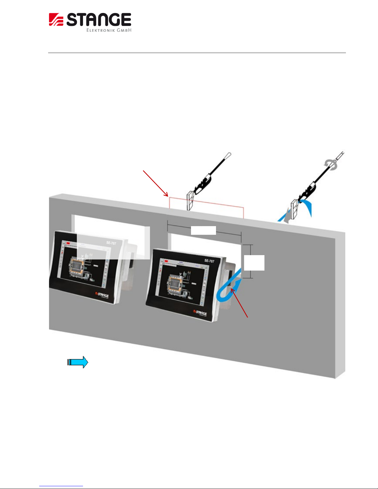
5.5 Front panel installation
Front panel installation SE-707:
A rectangular aperture is necessary for device installation in control panels and cabinets, etc.
- Push the device into the aperture from the front side.
- Attach the delivered mounting frame on the back side.
- Place one of the enclosed clamps from the back on each side until the stroke is reached; the recess in the metal
plate of the clamp grips to a nipple on the side of the housing.
- Turn the screw clockwise; the device is pulled backwards and secured.
Installation diagram
Holding clamps
354 mm
238
mm
Mounting frame
Minimum distance
for side by side
mounted devices:
25 mm
Control panel
or
cabinet
Nipple
Note
The mounting frame is
only required if the
function of the sealing is
needed.
Page 22
Program Controller SE-707
© 2018 by STANGE Elektronik GmbH
22 Subject to technic al modifications
6 Start-up
6.1 Guidelines for Grounding and Wiring
Proper grounding and wiring of all electrical equipment is important to help ensure the optimum operation of your system
and to provide additional electrical noise protection for your application and the SE-707.
Requirements:
Before you ground or install wiring to any electrical device, ensure that the power to that equipment has been turned off.
Ensure that the power to any related equipment has been turned off.
Ensure that you follow all applicable electrical codes when wiring the SE-707 and related equipment. Install and operate all
equipment according to all applicable national and local standards. Contact your local authorities to determine which codes
and standards apply to your specific case.
Warning !
Attempts to install or wire the SE-707 or related equipment with power applied could cause
electric shock or faulty operation of equipment. Failure to disable all power to the SE-707 and
related equipment during installation or removal procedures could result in death or serious injury
to personnel, and/or damage to equipment.
Always follow appropriate safety precautions and ensure that power to the SE-707 is disabled
before attempting to install or remove the SE-707 or related equipment.
Always take safety into consideration as you design the grounding and wiring of your SE-707 system. Electronic control
devices, such as the SE-707, can fail and can cause unexpected operation of the equipment that is being controlled or
monitored. For this reason, you should implement safeguards that are independent of the SE-707 to protect against possible
personal injury or equipment damage.
Warning !
Control devices can fail in an unsafe condition, resulting in unexpected operation of controlled
equipment. Such unexpected operations could result in death or serious injury to personnel,
and/or damage to equipment.
Use an emergency stop function, electromechanical overrides, or other redundant safeguards that
are independent of the SE-707.
Page 23
Program Controller SE-707
© 2018 by STANGE Elektronik GmbH
Subject to technical modifica tions
23
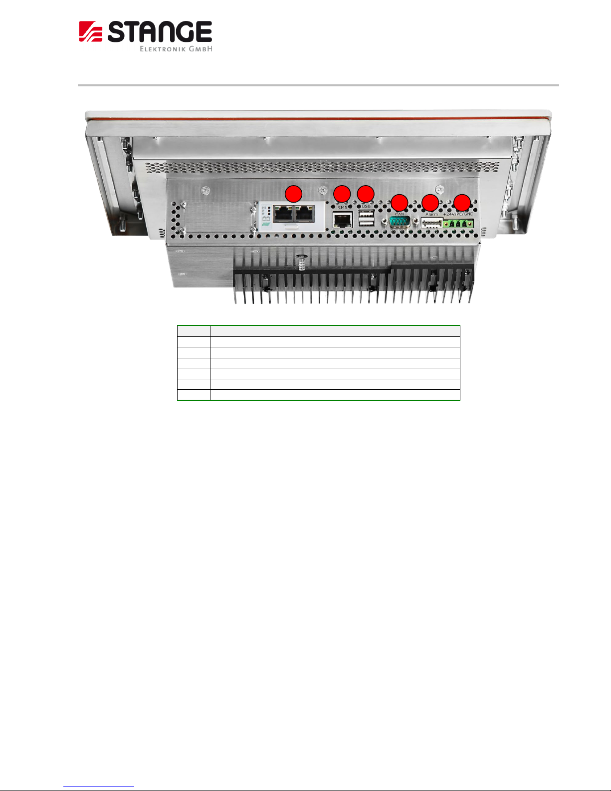
6.2 Overview of the connections
No.
Element
1
24 V DC power supply (+24V/PE/GND)
2
Alarm connector (A1,A2) for Watchdog and alarm output
3
CAN-connector 9 pol. Sub-D
4
USB 1 and 2
5
Ethernet RJ45
6
Option slot
6 1 4 5 2
3
Page 24
Program Controller SE-707
© 2018 by STANGE Elektronik GmbH
24 Subject to technic al modifications
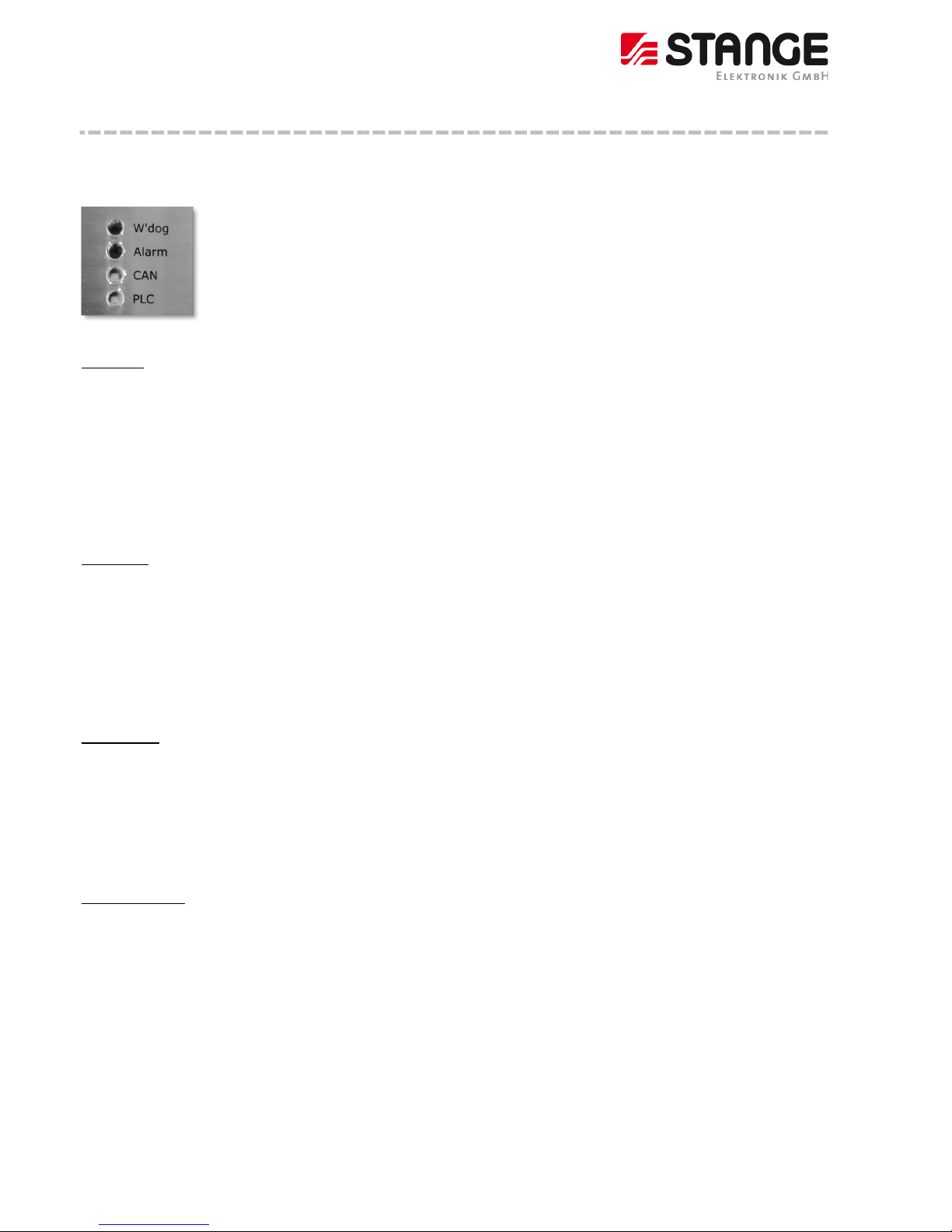
6.2.1 Function of the LED's at the back of the device
On the back of the device 4 LED's are located with the function described in the following:
LED4
LED3
LED2
LED1
LED 1: PLC
This LED gives information about the condition of the internal PLC:
- LED off: This is the condition during switching on the device until the normal device function is running
- LED flashes green: Device function running, PLC in the condition “RUN” (turn-switch position 0!)
- LED flashes yellow: The PLC is in the condition “STOP” (turn-switch position 1)
- LED flashes red: The PLC is in the condition “RESET” (turn-switch position 2)
- LED flashes red with 1 Hz: The PLC is in the condition “MEMORY RESET” (turn-switch position 3)
LED 2: CAN
This LED gives information about the condition of CANopen field bus function:
- LED flashes green: The field bus is running, all CAN slaves are online and no CAN slave configuration error is available!
- LED flashes red: CAN slaves not all online or CAN slave configuration error
- LED flashes red with 2 Hz: BusOff-Error
- LED off: CAN interface inactive, PLC is in condition „RESET“ (turn-switch position 2 or 3)
LED 3: Alarm
This LED gives information about possibly acknowledged alarms:
- LED off: No error or alarm processing inactive (PLC not running, turn-switch not in position 0)
- LED flashes red with 1 Hz: At least one new alarm is available
- LED flashes red: Only acknowledged alarms are available
LED 4: Watchdog
This LED gives information about the condition of the Watchdog:
- LED off: No error or device off
- LED flashes red: The Watchdog has triggered, a serious problem is available.
Page 25
Program Controller SE-707
© 2018 by STANGE Elektronik GmbH
Subject to technical modifica tions
25
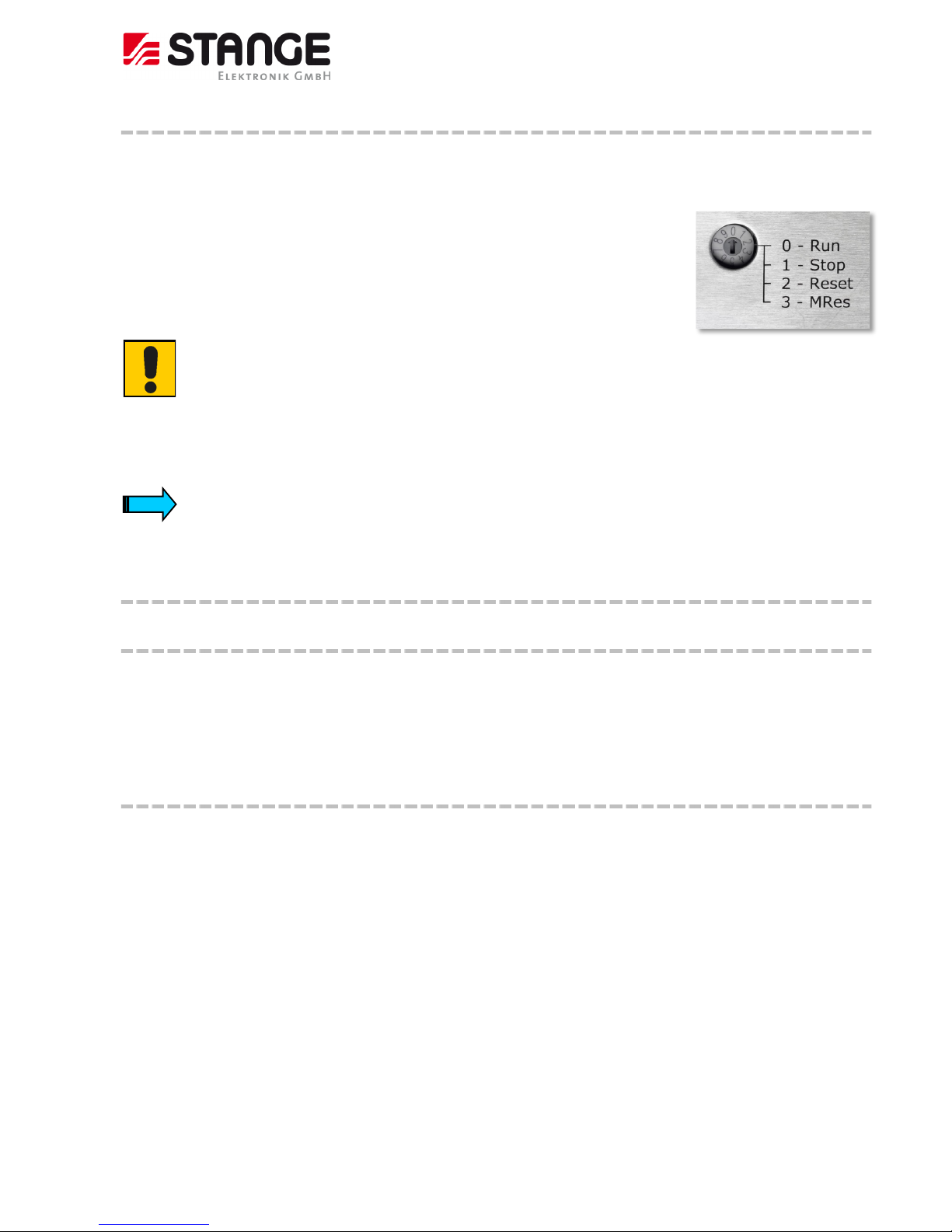
6.2.2 Turn-switch for PLC operating mode selection
A turn-switch for PLC operating mode selection of the internal PLC is located on the on the back of the device.
The turn-switch has positions from 0 to 9, only the first 4 positions are assigned:
Position 0: PLC takes “RUN” condition
Position 1: The PLC goes to “STOP”;
Position 2: The PLC makes a “RESET”;
Position 3: The PLC makes a “Memory-RESET”;
Positions 4 to 9 are not defined and should not be used!
ATTENTION!
The turn-switch should always remain in position 0!
All other positions have important effects to the operation and also possibly on the safety of the plant and might only be
used by experienced personnel of the plant manufacturer!
The turn-switch may only be turned very slow from one position to another. If the switch is turned too fast, then a
condition may be jumped over or not be recognized.
6.2.3 System Watchdog
6.2.3.1 General
The SE-707 device hardware has a hardware watchdog with an output as potential-free semi-conductor relay output lead
through at a device connector.
If the Watchdog output is really evaluated depends on the discretion of the plant manufacturer!
6.2.3.2 Mode of operation
The “Good” state of the Watchdog output is a closed contact. If the device is turned off or the Watchdog drops-out, then the
relay contact opens.
The contact of the Watchdog relay is typically used in an emergency stop chain. The Watchdog contact can alternatively be
used for the triggering of an alarm light, however the connecting signal must be inverted with the help of a coupling relay
(break contact make-contact).
If the device Watchdog releases, a serious problem is existent, a normal operation of the plant is not given.
The Watchdog does not directly effect on the device, i.e., the control runs forward as far as it is possible.
If the Watchdog is dropped-out one-time, this state can only be removed by a hardware reset (i.e., power on/off).
Page 26

Program Controller SE-707
© 2018 by STANGE Elektronik GmbH
26 Subject to technic al modifications
With the Watchdog is monitored whether the PLC works correct i.e.:
1. It is monitored whether the PLC run time system runs.
2. It is monitored whether the PLC was stopped because of an error (division by zero, ... etc.).
3. It is monitored whether the PLC was stopped because of a software Watchdog overflow.
Please note: The Watchdog contact does not open if the PLC was brought to the “Stop” state with the turn-switch at the
device back-side or with the programming system!
The state of the Watchdog relay is represented from LED 4 on the device back-side:
LED 4 off: Device free from tension or Watchdog relay contact closed
LED 4 on: The Watchdog relay contact is opened, i.e., a serious problem is given
6.2.3.3 System logger entry
A system logger entry is generated if the watchdog triggers off. This entry can be read off together with other system events
by manufacturer´s support and give helpful notes in case of device repair.
Further system events are for example: device switching on and off, turning the turn-switch on the device rear side, etc.
Note: If a hardware defect is really existent it is not sure that such a system event entry could really be written to the file!
6.2.4 The alarm relay
6.2.4.1 General
At the back side of the SE-707 devices an alarm relay is lead through (floating semi-conductor relay output, make-contact).
If the alarm output is really evaluated in the plant, depends on the discretion of the plant manufacturer!
6.2.4.2 Mode of operation
The “good” state of the alarm relay is an opened contact.
For each single configured alarm can be freely determined in the alarm processing of the SE-707, whether there should be an
influence on the alarm relay in case of alarm, or not.
Only internal device alarms with alarm numbers >200 have influence on the alarm relay.
The alarm contact remains closed until no alarm is available with selected alarm relay activation, i.e. all these alarms must be
acknowledged and gone.
The turn-switch on the device rear side must be in position “RUN” so that the alarm contact displays correct. In all other
positions the alarm contact is opened.
Page 27
Program Controller SE-707
© 2018 by STANGE Elektronik GmbH
Subject to technical modifica tions
27
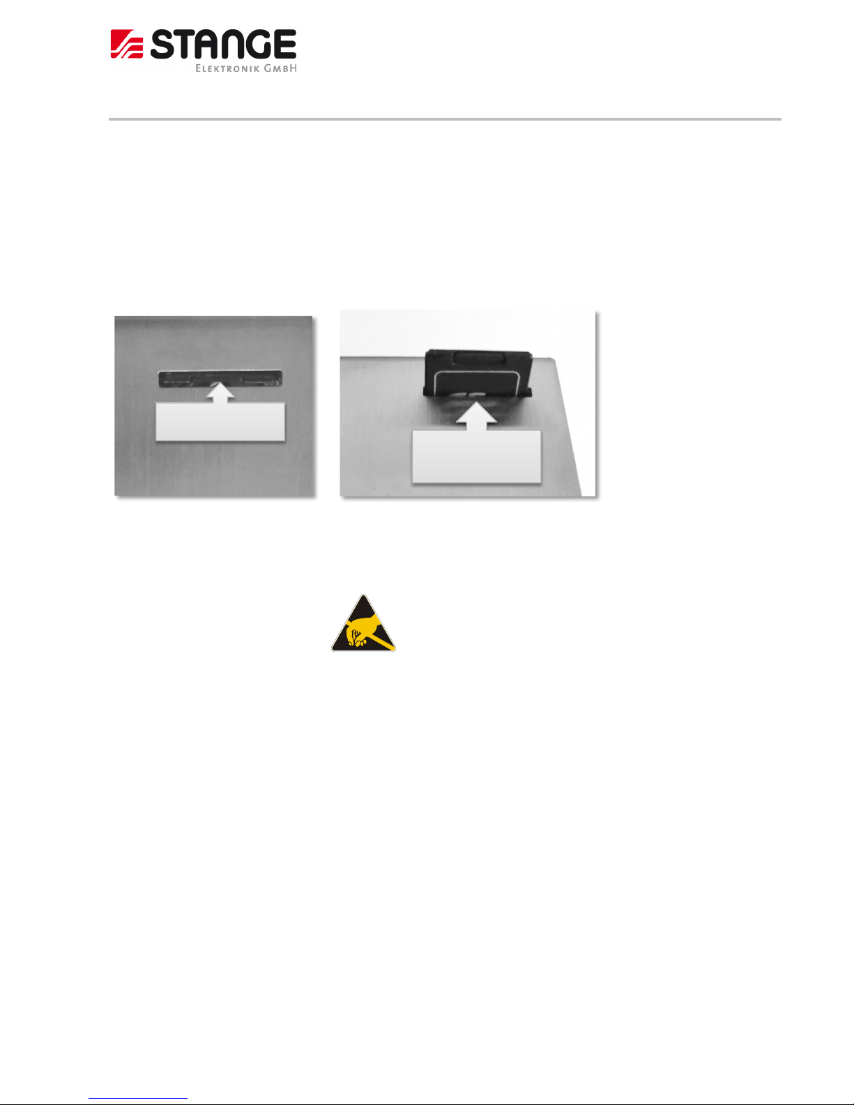
6.3 Mounting / dismounting the SD card
The mounting and/or dismounting of the SD™ medium is possible like follows:
• Press in the SD card slightly with a suitable object (e.g. a flat screwdriver) up to the stop. Afterwards pressing can be
stopped and the SD card is removed (SD card: large opening on the left side of the device).
• When mounting a SD medium it must be inserted carefully and with the right direction into the opening and be
pressed as far as it will go with above mentioned screwdriver. The card locks if the tool pressure is taken away. Take
care for the correct orientation of the medium. The contact area is located to the device rear panel!
Attention: Electrostatic discharges may destroy electronic
components!
You must wear a grounded bracelet, or, if this is not practicable,
at least care for a potential equalization by touching a grounded
metal part like e.g. the device housing, if you work with the data
storage medium.
The SD™ medium must be kept in an antistatic box.
SD card slot
Press in the SD card
up to the stop
Page 28
Program Controller SE-707
© 2018 by STANGE Elektronik GmbH
28 Subject to technic al modifications
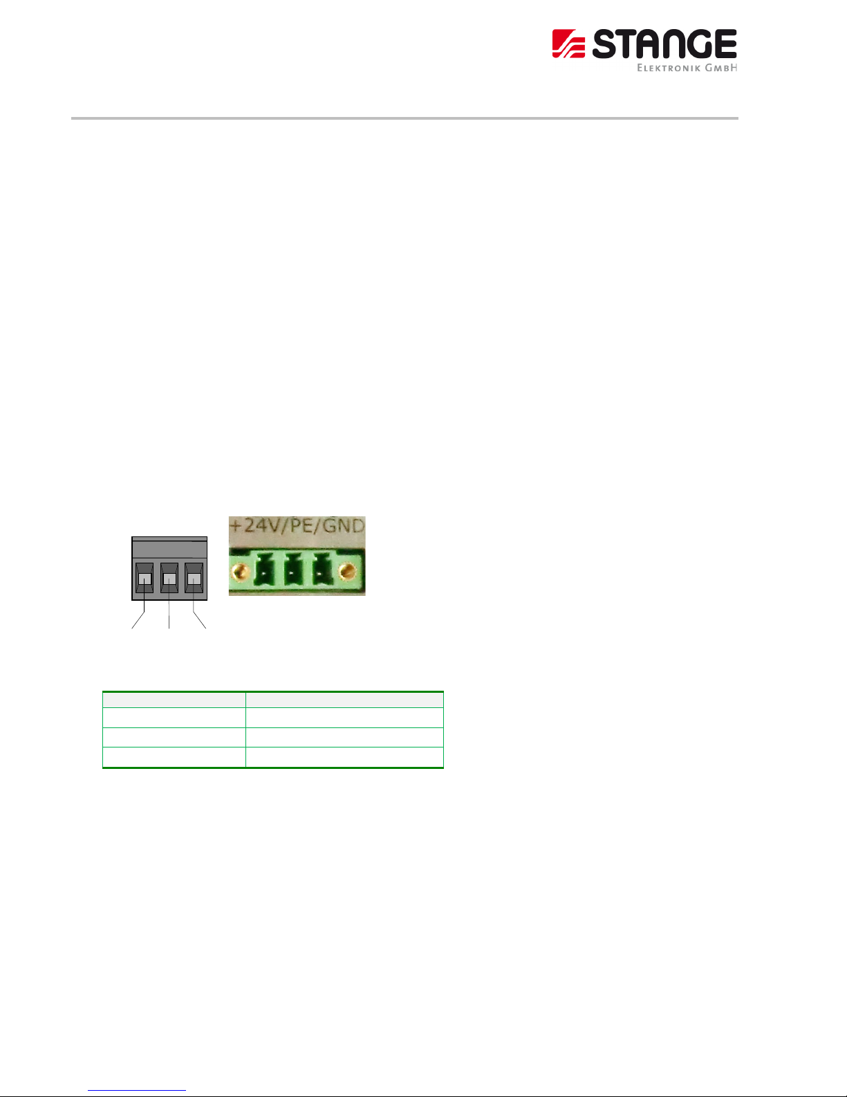
6.4 Connecting the power supply
The SE-707 device belongs to protection class 3. The system power supply must be provided with a 24VDC SELV voltage
(safety extra-low voltage). The internal voltage conditioning unit is equipped with a galvanic isolation. The PE connection is
directly connected to the housing potential. The device is protected with a 2AT soldered-in fuse. A reverse polarity protective
device is used to protect the device in the event of reversed poles. Operation, however, is only possible if the connection was
made correctly.
Connections for the SE-707 must comply with specific, local regulations.
The connection must be made as follows:
1) The cross-section of the power supply cable must be at least 0.75 mm² and a maximum of 2.5 mm².
2) A flexible lead or wire can be used for the connection, whereby the end should be equipped with a cable end
sleeve.
3) The current consumption must be taken into account when implementing the power supply. The functional earth
is not compulsory for operation. The PE connection is directly connected to the housing potential
The plug connector (socket connector with screw terminals) is supplied with the device for connection.
Connector assignment
Designation
Function
+24 V DC +24 V DC power supply
PE Functional ground
GND 0 V power supply
+24VDC PE GND
(plug con nector: P hönix MC 1.5/3-STF-5.08
Phönix Art. Nr. 1847369)
Page 29
Program Controller SE-707
© 2018 by STANGE Elektronik GmbH
Subject to technical modifica tions
29
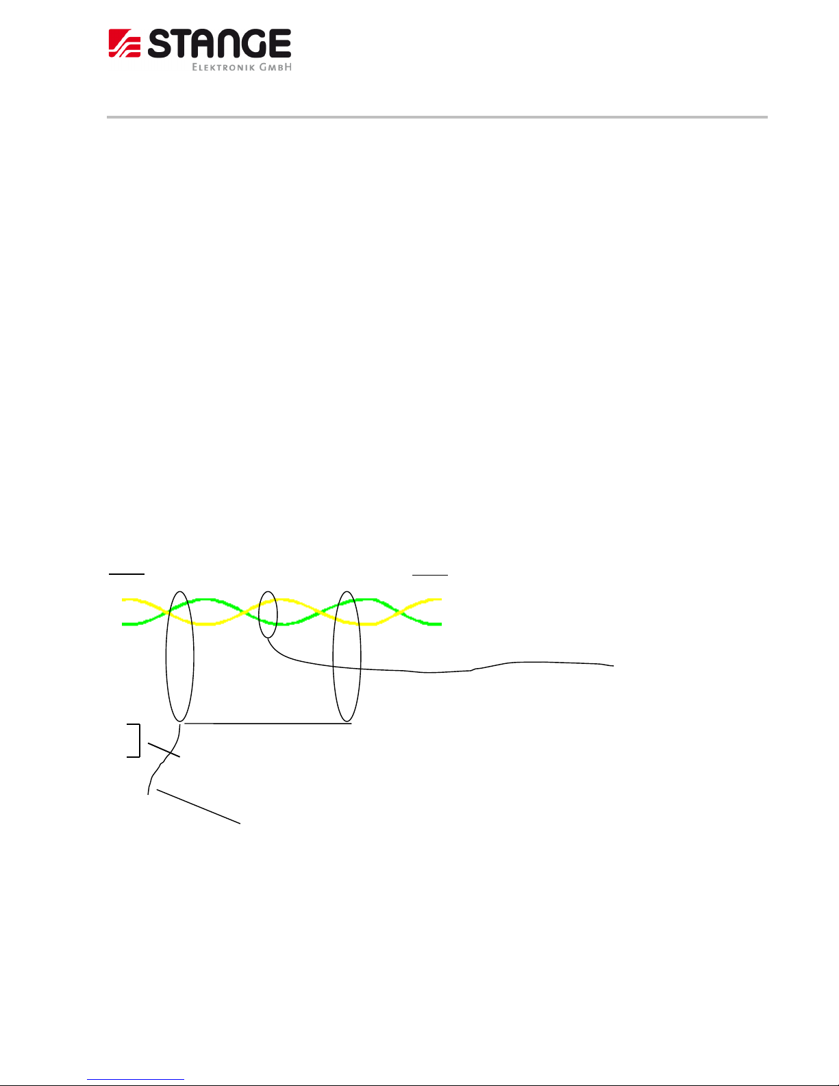
6.5 Packaging the CAN cable with shield connection
The preparation of the data and signal cables is an important factor for the electromagnetic compatibility (EMC) of this
SE-707, both in terms of interference immunity and emission.
The RS232 interface and CAN interface are connected via D sub miniature plug connectors in accordance with DIN 41652.
Only use metal or metallised connector casings with a cable clamp for strain relief fastened or clamped on the connector. The
clamping of the cable shield ensures an optimum contact area and a low impedance connection with the connector casing of
the SE-707 program controller.
The following procedure is recommended for making the low-impedance connection for the cable shield:
1. Strip the cable.
2. Shorten the exposed shield braid by approx. 3 cm.
3. Turn back the braid over the cable sheath.
4. Use a heat shrinkable tubing or rubber grommet to cover the exposed cable sheath with the folded back shield braid
so that 5 to 8 mm of exposed cable shield is left at the sheath end and is cleanly covered at the back.
5. Fit the connector
6. The cable is then fastened at the exposed shield braid and the cable sheath below it directly underneath the cable
clamp strap of the connector casing.
ATTENTION: When using plastic plugs, with which the strain relief is not connected with the plug earth
connection, the screen network must be soldered on directly at the plug earth connection.
Connection SE
DSUB 9pol.
Socket
2
7
3
6
shield
4
5 220 Ohm terminal resistance
is active in the SE-707 via bridge
Plug housing
put shield on
plug housings
Line:
Execution: twisted in pairs with common shield. Shield presented on one side of the unit.
(e.g.: HELUKABEL “Li-2YCY” (2x2x0.22 / Order.-No.: 21111))
Connection CAN – Base or SIOS
DSUB 9pol.
Socket
2 CAN -Low
7 CAN-High
3
6
4
5
Plug housing
Line:
twisted in
pairs
Page 30
Program Controller SE-707
© 2018 by STANGE Elektronik GmbH
30 Subject to technic al modifications
Connection work should be carried out with special care in order to ensure
trouble-free operation.
The EMC values stated in the technical data can only be guaranteed if the
cables are prepared according to the following specifications.
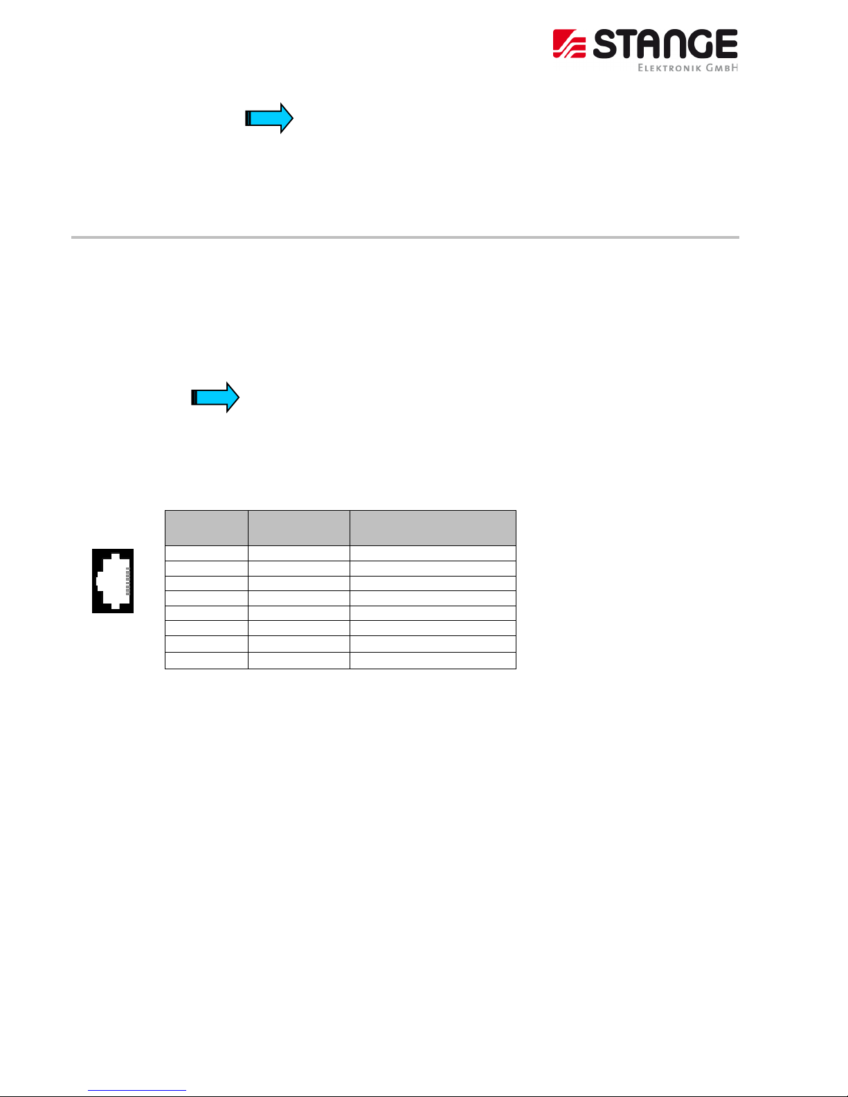
6.6 Connecting the programming interface RJ45
The programming is carried out via the standard Ethernet interface (RJ45). The connection to the programming PC is
implemented using a standard Ethernet cable (1:1) via a hub or directly using a crosslink cable. The cables are also available as
an accessory.
Before the device is connected to the Ethernet network, the IP address of the device and the programming PC must be set.
IP addresses can be obtained from your system or network
administrator. IP addresses must be uniquely defined in an
Ethernet net
work. The IP address of all networks and of the
programming PC must be in the same subnet work (e.g.
192.168.0.xxx).
Connector assignment:
RJ45
connector
Pin-No.
Signal
Description
1 TXD- 2 TXD+ 3 RXD+
4 -
5 - 6 RXD-
Socket, 8pole
7
-
RJ45
8
-
Cables connected to the programming interface must be laid separately from the low-voltage cables.
1
2
3
4
5
6
7
8
Page 31

Program Controller SE-707
© 2018 by STANGE Elektronik GmbH
Subject to technical modifica tions
31
6.7 Connection CAN
The communication interface is defined in accordance with the CiA CAN Specification V2.0 part B. The fully-integrated CAN
unit supports the sending and receiving of frames with an 11-bit identifier. The type of configuration selected depends on the
software protocol. The baud rate can be selected in a wide range, and only the standard CiA baud rates are implemented
(recommended 125kBaud max.). The SE-707 is the master on the CAN bus.
Connector
Pin-No.
Signal
Description
1
2
CAN LOW
Negative
data
signal
3
4
5
6
7
CAN HIGH
Positive data signal
9pol
8
SubD
9
Case
Case
Cable shield
The CAN interface is isolated.
The max. Baud rate is 500kBit/s.
Recommended setting: 125kBit/s
The CAN terminating resistor is realized internally and a part of the
device, but must however be activated over a bridge from 4 to 5.
There is no power supply lead to the CAN
connector for external
devices.
5
9
4
8
3
7
2
6
1
Page 32

Program Controller SE-707
© 2018 by STANGE Elektronik GmbH
32 Subject to technic al modifications
Wiring instructions
The stations on the bus system are connected via fieldbus lines complying with ISO 11898. The cables must accordingly have
the following electrical characteristics:
Parameter
Abbreviation
Unit
Value
Value
Value
Note
min.
nom.
max.
Impedance
Z Ω 108
120
132
Measured betwee n two
signal lines
Specific
resistance
r
mΩ/m 70 For the receiver module,
the differential voltage on
the bus cable depends on
cable resistance between
it and t he sender
Cable delay
ns/m 5 The minimum delay
between tw
o points on
the bus is 0. The
maximum delay is
determined by the bit
timing and the delays of
the sender and receiver
circuits
The figure shows the minimum wiring with shielding between two bus stations with the Sub-D connector as an example. A
bus terminating resistor (220 Ohm between Pin 2 and Pin 7) must be connected at the beginning and the end of each CAN
bus. Do not swap around the two signal wires!
For a detailed representation see chapter “Packaging the CAN
cable with shield connection”
Baud rate and cable lengths
Baud rate
Max. length
20 kBaud
1600m
50 kBaud
800m
100 kBaud
400m
125 kBaud
320m
250 kBaud
160m
500 kBaud
80m
Protective ground
Shield
Interface 1 Interface 2
Shield
Inside: twisted pair cable
Station
Station n
Bus terminating r esistor
Page 33

Program Controller SE-707
© 2018 by STANGE Elektronik GmbH
Subject to technical modifica tions
33
6.8 Connection of the alarm socket
An external signalling of internal collective alarms and the watchdog is possible via alarm connector.
Alarm Power
+ 24V PE GND
Technical data of the alarm relays:
Type:
semiconductor relay
Voltage:
24 V AC/DC max.
Current:
300 mA max.
On-resistance:
4 Ohm max.
Alarm connector: Wago multipole connector Art.-No. 733-106, maximum cross section: 0,5mm²
Function Watchdog and Alarm at SE-707:
Watchdog
No voltage
No
Yes
Alarm 1 - contact:
Open
Closed
Open
Internal alarm
No voltage
No
Yes
Alarm 2 - contact:
Open
Open
Closed
→ Overview of the connections: See chapter 6.2
6.9 Connection of the PROFIBUS-DP-Slave interface (Option)
Please ensure that termination resistors are available at both ends of
the cable. If special PROFIBUS connectors are being used, these
resistors are often found inside the connector and must be switched
on.
For baud rates above 1.5 MBaud use only special connectors, which
also include additional inductance.
It is not permitted to have T-stubs on PROFIBUS high baud rates. Use
only a special cable which is approved for PROFIBUS DP. Make a solid
connection from the cable shield to ground at every device and make
sure that there is no potential difference between the grounds at the
devices.
Alarm 1: Watchdog
(break contact)
Alarm 2: System alarm
(closer)
Not used
Page 34

Program Controller SE-707
© 2018 by STANGE Elektronik GmbH
34 Subject to technic al modifications
If your device or your card is linked with only one other device on the bus, both devices must be connected to the ends of the
bus line. The reason is that these devices must deliver the supply voltage for the termination resistors. If three or more
devices are connected to the bus, the Master device can be connected at any desired position.
Figure: PROFIBUS Network
Up to 32 PROFIBUS devices can be connected to one bus segment. If several bus segments are linked to each other with
repeaters, there can be up to 127 devices on the network at maximum.
The maximum permissible cable length of a PROFIBUS segment depends on the baud rate used, see the following table.
Baud rate in kBit/s
Max. distance
9,6
1.200 m
19,2
1.200 m
93,75
1.200 m
187,5
1.200 m
500
400 m
1.500
200 m
3.000
100 m
6.000
100 m
12.000
100 m
Table: PROFIBUS Segment length in dependence of the baud rate
Only PROFIBUS certified cable, preferably the cable type A, should be used.
The following table contains the most important electrical data concerning PROFIBUS certified cable:
Parameter
Value
Impendence
150 Ω ± 15 Ω
Capacity per units
length
< 30 pF/m
Loop resistance
110 Ω/km
Wire gauge
0,64 mm
Table: Characteristics of PROFIBUS certified Cable
Page 35

Program Controller SE-707
© 2018 by STANGE Elektronik GmbH
Subject to technical modifica tions
35
The following picture shows the pinning of the PROFIBUS interface of the netJACK communication module:
Figure: Pinning PROFIBUS DP interface (D-Sub-female connector, 9-pole)
PIN
Signal
Description
3
RxD/TxD-P
Receive-/Send data-P (Line B at plug)
5
DGND
Data reference potential
6
VP
Power supply (positive)
8
RxD/TxD-N
Receive-/Send data--N (Line A at plug)
Table: Pinning PROFIBUS DP interface
Note:
The PROFIBUS interface is a potential free RS-485 interface according to PROFIBUS Standard EN 50170.
For the hardware connection no 90° or connectors with inclined outlet can be used. Connectors with axial cable outlet need
more space under the device.
Front view of netJACK with PROFIBUS DP
System LED:
The subsequent table describes the meaning of the System LED of the system and the Profibus LED communication module.
LED
Color
State
Meaning
SYS
Duo LED yellow/green
Green
On
Operating system is running.
Green / yellow
Blinking
Second stage bootloader is waiting for firmware.
Yellow
On
Bootloader netX (= romloader) is waiting for second stage bootloader.
Off
Off
Power supply for the device is missing or hardware defect.
Table: System status LED states
Page 36

Program Controller SE-707
© 2018 by STANGE Elektronik GmbH
36 Subject to technic al modifications
LED
Color
State
Meaning
COM
Duo LED red/green
Green
On
Communication to all Slaves is established.
Green
Blinking (5 Hz)
PROFIBUS is configured, but the bus communication is not yet
released from the application.
Green
Flashing,
acyclic
No configuration or faulty configuration.
Red
Blinking (5 Hz)
Communication to at least one Slave is disconnected.
Red
On
Communication to all Slaves is disconnected or another serious
error has occurred.
Redundant Mode: The active Master was not found.
Off
Off
Device is not switched on or supply voltage is missing.
Table: LED states for the PROFIBUS DP Master protocol
LEDs states
Definition
Blinking (5 Hz)
The indicator turns on and off with a frequency of 5 Hz:
“on” for 100 ms, followed by “off” for 100 ms.
Flashing, acyclic
The indicator turns on and off in irregular intervals.
Table: LED state definitions for the PROFIBUS DP Master protocol
Page 37

Program Controller SE-707
© 2018 by STANGE Elektronik GmbH
Subject to technical modifica tions
37
6.10 Connection of the PROFINET IO Device (Slave) interface (Option)
The following picture shows the pinning of the Real-Time Ethernet interface of the communication module.
Figure: Pinning of Ethernet connectors
Pin
Signal
Description
1
TX +
Transmit Data +
2
TX –
Transmit Data –
3
RX +
Receive Data +
4
TERM
Bob Smith Termination
5
TERM
6
RX –
Receive Data –
7
TERM
Bob Smith Termination
8
TERM
Table: Ethernet interface channel 0 and channel 1 pin assignments
Note
Auto-crossover function is supported by the netJACK modules.
Page 38

Program Controller SE-707
© 2018 by STANGE Elektronik GmbH
38 Subject to technic al modifications
Front view PROFINET IO
System LED:
The following tables describe the meaning of the system and PROFINET IO Device (Slave) LEDs of the communication module.
LED
Color
State
Meaning
SYS
Duo LED yellow/green
Green
On
Operating system is running.
Green/Yellow
Blinking
Second stage bootloader is waiting for firmware.
Yellow
On
Bootloader netX (= romloader) is waiting for second stage bootloader.
Off
Off
Power supply for the device is missing or hardware defect.
Table: System status LED states
LED
Color
State
Meaning
SF
(System Failure)
Duo-LED rot/gr een
Off
Off
No error
Red
Flashing (1 Hz, 3 s)
DCP signal service is initiated via the bus.
Red
On
Watchdog timeout; channel, generic or extended diagnosis
present; system error
BF (Bus Failure)
Duo LED red/green
Off
Off
No error
Red
Flashing (2 Hz)
No data exchange
Red
On
No configuration;
or low speed physical link; or no physical link
LINK
LED green
Green
On
The device is linked to the Ethernet.
Off
Off
The device has no link to the Ethernet.
RX/TX
LED yellow
Yellow
Flickering (load
dependent)
The device sends/receives Ethernet frames.
Off
Off
The device does not send/receive Ethernet frames.
Table: LED states for the PROFINET IO-Device protocol
LED state
Definition
Flashing
(1 Hz, 3 s)
The indicator turns on and off for 3 seconds with a frequency of 1 Hz:
“on” for 500 ms, followed by “off” for 500 ms.
Flashing
(2 Hz)
Di The indicator turns on and off with a frequency of 2 Hz:
“on” for 250 ms, followed by “off” for 250 ms.
Flickering (load
dependent)
The indicator turns on and off with a frequency of approximately 10 Hz to indicate high Ethernet
activity: "on" for approximately 50 ms, followed by "off" for 50 ms. The indicator turns on and
off in irregular intervals to indicate low Ethernet activity.
Table: LED state definitions for the PROFINET IO-Device protocol
Page 39

Program Controller SE-707
© 2018 by STANGE Elektronik GmbH
Subject to technical modifica tions
39
6.11 Connection of a PC with the SE-707
6.11.1 Cabling
The communication from the PC to the control takes place ideally over Ethernet and TCP/IP protocol. With a direct
connection, without Ethernet-Hub or Switch, a crossed "Crossover" cable is to be used. Control-laterally a standardized RJ45
socket is attached.
crossed RJ45 TwistedPair cable
If the Ethernet connection is made over an Ethernet-Hub and/or a Switch, the connection is to be made by normal (not
crossed) cables from the Hub to the programmer as well as to the programming PC.
not crossed RJ45 TwistedPair cable
6.12 Settings of the PC for Ethernet communication
6.12.1 Separation of automation network and company/office network
Company/office nets typically consist of computers that have usually also direct access to the Internet. A separation of
automation net and company/office net is urgently advised. Only in this way is ensured that the connection of automation
devices among each other and/or to the control system computer is not impaired by disturbances in the company/office net,
e.g. by computer viruses, network attacks from the outside, defective office PC's or by strong network capacity utilization.
The 6xx devices should be provided necessarily with a separate network strand (separate subnet) and be attached over its
own network interface card to the control system PC. If desired the control system PC can be integrated over a second
network interface card to the company/office net.
Page 40

Program Controller SE-707
© 2018 by STANGE Elektronik GmbH
40 Subject to technic al modifications
6.12.2 Length of the network line (segment length)
The network line to the next Hub/Switch may not be longer than 75 to 100 m!
6.12.3 Requirements
Based on the fact that the following conditions are given...
• a network board is available and correctly inserted in the system
• the physical connection (network cable) with a network board with RJ45 connection is displayed by the appropriate
LED
• the communication with other systems with appropriate protocols, e.g.: Windows Peer to Peer, is possible
... describes this chapter how the IP address is adapted exemplarily at the operating system WIN 7.
6.12.4 Settings Windows 7/10
The net-referred settings can be adapted like follows:
Windows: <Start> … <Control Panel> … <Network and Sharing Center>
Network and Sharing Center: <Change adapter settings>
In this window all active connections are displayed (e.g. in case of
several network boards).
By clicking the LAN connection and select <Properties> or via <File>
<Properties> the window with the LAN connection properties is
opened.
In the window <Local Area Connection Properties> the item <Internet Protocol
Version 4 (TCP/IPv4)> must be selected by double click.
Page 41

Program Controller SE-707
© 2018 by STANGE Elektronik GmbH
Subject to technical modifica tions
41
Now the window with the <Internet Protocol Version 4 (TCP/IPv4) Properties>
appears.
Here a reasonable value must be entered at <IP-Address>
and <Subnet mask>.
Example for an IP address: 192.168.0.58
Example for a subnet mask: 255.255.0.0
Windows 7/10 takes over changes without a restart!
6.12.5 Settings of the IP-address in the device
By the delivered visualization application
With the delivery of a SE-707 control, a visualization application is installed, which permits to adjust the IP-address.
How the address has to be entered is explained in chapter
→ Host Interface.
After the input of the IP-address, the device has to be switched off and on again, so that the changed address is activated.
Page 42

Program Controller SE-707
© 2018 by STANGE Elektronik GmbH
42 Subject to technic al modifications
7 Operation
7.1 Start-up behaviour
The SE-707 carries out a system test after power on. The PLC does not switch to Run or Stop until no hardware errors have
been found. The system test includes the following:
• Memory test
• Flash disk test
7.2 Shutdown behaviour
Voltage dips of <= 10ms at 24V are bridged by the power supply unit. Longer voltage dips will cause the PLC to be reset
automatically.
ATTENTION !
Writing data to the CompactFlash™ during a power supply
failure will cause data loss!
The ECS-EPAM visualization
software therefore makes a copy
of the file in the directory C:\
BACKUP before every write
operation. These files are restored if necessary at the start.
Page 43

Program Controller SE-707
© 2018 by STANGE Elektronik GmbH
Subject to technical modifica tions
43
7.3 Start-up behaviour / starting
After switching on the tension, the user program is loaded from the CompactFlash™ into the RAM and the PLC is started.
Procedure:
Power on
PLC-
Programm
present
?
Battery
o.k.
?
Reset-cold
Start (PLC.INI)
PLC- Status:
„Run“
PLC- Status:
„Stop“
PLC- Status:
„System Fault“
PLC-Status:
„Power on“
Startup=WARM
(Default)
?
Startup=STOP
?
Hardware-
o.k.
?
No
No
No
No
Page 44

Program Controller SE-707
© 2018 by STANGE Elektronik GmbH
44 Subject to technic al modifications
8 Operating dialogue of the control software
The operating dialogue of the control software is divided into three ranges:
Configuration: Here the pre-settings of the operating parameters are made.
Program: Here the programs (recipes) are created and edited.
Operation: Here operating functions for the plant are made available.
The sidebar on the right and left screen side offers further menu items. The right sidebar allows calling additional functions
and on the left sidebar is changed to other pages.
Note:
The unit operation depends on the configuration of the respective unit(s) and values. Therefore the layout of the display
can deviate. This example shows however the basic operation of the SE-707 devices.
8.1 Operation
Warning
If you do changes in OPERATING mode, the changes immediately affect
process operation. Changing the program in OPERATING mode can result
in unexpected system operation that can cause death or serious injury to
personnel, and/or damage to equipment.
Only authorized personnel who understand the effects of OPERATING
mode edits on system operation should perform an OPERATING mode
edit.
Page 45

Program Controller SE-707
© 2018 by STANGE Elektronik GmbH
Subject to technical modifica tions
45
8.1.1 Start screen
The device starts with the operation overview screen after switching on.
At first you have to log on by operating the “LogIn” button. Login access data for the first device start for the administrator
are: User: administrator, Password: Stange .Replace the default password by your own password!
Further information in the following chapter:
→ User Administration.
Start screen LogIn access data input
All necessary functions for plant operation are displayed on the operation overview screen for selection. By selecting the
requested function the menu changes to the corresponding part of the program.
8.1.2 Programmer
The data of the actual (i.e. loaded to the operating memory)
program is displayed on the programmer screen (here first the
tabular representation; Graphic presentation with the program
curve is considered in the next chapter).
The following parameters are displayed in the overview:
- Set value number / digital track number
- Set value designation / digital track designation
- State (increasing, constant, decreasing, manual, auto, error)
- Actual (value and/or “On” and “Off”)
- Dimension
The “Error” state may result for digital tracks (normally in connection with a manual operation of tracks). In this condition
the appropriate track wants to switch on, but is prevented by a locking against another track, already switched on. Track
locking is defined in the configuration.
Control functions (right sidebar):
Start Program start from the beginning (from state RESET or END);
Continuation of the program (from state HOLD)
→ Program start with data logger
Hold Program hold (from state RUN)
Reset Cancel program and (re-)set to standard values
Manual Switching to manual operation of the actual marked value
Auto Switching to automatic operation of the actual marked value
Jump Jump in the program
Page 46

Program Controller SE-707
© 2018 by STANGE Elektronik GmbH
46 Subject to technic al modifications
8.1.3 Manual operation for set value and tracks (”Manual”)
Set values and digital tracks can – after selecting and operating the
“Manual” button – be manipulated by the operator even during
running program.
Set values are directly overwritten via input window.
Digital tracks can be set to active ( “On” ) or inactive ( “Off” ) and
remain this condition as long as they are reset to their preprogrammed state.
ATTENTION!
Manual set values and tracks are reset to pre-programmed values in case of:
- Operating the “Auto” button or a “Auto” instruction of a control system
- Loading a new programmer into the operating memory (can be blocked in the configuration)
NOTE:
Track interlocks specified at configuration are also considered in manual operation.
8.1.4 Program curve
The program curve consists of set value curve (upper graph) and
track view (bottom graph). Further set values and/or tracks can be
displayed by operating the corresponding button.
Left next to the set value curve and the track view is displayed
which line colour corresponds to which value. The actual value of
the set value and the unit are displayed. The actual condition of
the tracks is represented by the symbols “-“ for active (On) and “/”
for inactive (Off).
Control functions (right sidebar):
Start Program start from the beginning (from RESET or END state);
continuation of programs (from HOLD state)
→ Program start with data logger
Hold The program is stopped
Reset Cancel program and (re-)set to standard values
Set values + Further set values are displayed
Track+ Further tracks are displayed
Jump Jump in program
The left value scale can be adapted to the respective set value by touching the scale.
Page 47

Program Controller SE-707
© 2018 by STANGE Elektronik GmbH
Subject to technical modifica tions
47
8.1.5 Program jump
Options for program jump are displayed by operating the “Jump”
button.
Jump time Jump to segment time
Jump set value Jump to set value
Jump program time Jump to program time
Jump segment +1 Jump to the next segment
End Jump to program end
Controlling Call of the control functions
Inputs which exceed the total segment time are not accepted in case of jump to segment time. The inputted time value is
balanced from segment start and the jump is executed at once. The screen automatically switches to set value curve 1, the
new segment remaining time is displayed. In case of HOLD state before the jump it is kept even afterwards; in all other cases
the program runs after jump execution (RUN).
NOTE:
Program loops are not ignored! Special attention is to be paid for programs with loops for “Jump Segment Time” and “Jump
Set Value” which should be entered with segment number. The same input of a jump may result in different targets within
the program with loops depending on actual position in program (at the beginning in reset state, right in the middle in any
segment, at the end of the program, …)!
A jump to a segment within a program loop will cause the executing of the complete loop.
8.1.6 Automatic Program Start
A start time can be entered in the RESET state of the programmer on the program curve page and on the page with the
program table via right sidebar button.
The actual loaded program in the operating memory is
automatically started exactly at the entered time (date, time) (as if
the “Start” button would be pressed).
Date and start time are displayed left next to the OPERATION
writing in inverted representation if an automatic start is
programmed.
An entered start time is deleted if:
• the „Start off“ button is operated,
• the program is started in other way,
• or a program is loaded from the program memory into the
operating memory.
The entered start time can be up to 31 days in the future. Another future start time is not accepted.
Page 48

Program Controller SE-707
© 2018 by STANGE Elektronik GmbH
48 Subject to technic al modifications
8.1.7 Program change in actual segment
If setpoint and/or time values are edited in the running segment (RUN
or STOP status), the new value is activated - originating from the actual
program point (AP) – immediately in form of a ramp (see figure right).
A setpoint value jump (see adjacent figure) is realized by 1. setting the
setpoint value in the actual and in the previous segment onto the
required value, 2. performing a program jump onto the actual program
point (AP); the appurtenant moment of segment time must be entered
(see the following section).
A program loop which is already started is concerned by program modifications only if it is situated within a larger one. In
this case the inner loop takes over the new values when the outer one returns to start again.
8.1.8 Editing of the operating program
The operating program screen is reached by the left sidebar on the screen.
A program which is located in the operating memory can be tested and changed on the numeric operating data page with the
same functions and displays just like at programming. For this purpose also belongs graphs for set values and tracks which
are called by the corresponding button (graph, track).
ATTENTION!
Here made changes are not taken over to the program memory! They are only valid for program data in the operating
memory.
Operating program segments overview. The following parameters
of the actual operating program can be changed by selecting a
segment:
- Set values
- Tracks
- Change process step number
- Insert segment
- Copy segment
- Delete segment
Page 49

Program Controller SE-707
© 2018 by STANGE Elektronik GmbH
Subject to technical modifica tions
49
8.1.9 Controller
Control zones overview.
The following values are displayed in the overview:
- Control zone number
- Designation of the control zone
- Set value
- Actual value
- Dimension
- Manipulated output Y [%]
- State: “Auto” Normal controller operation
“Manual” Controller output set to man. value
“DISA” DisableAuto: Controller in normal
control operation but deactivated at present
“DISH” DisableHand: Controller output set on manual value but deactivated at present
“Opti”Self-optimization of control zone is active (in such a case the headline flashes)
- Limit value “G”: “↑”in case of an overshooting of the upper control zone limit values
“↓”in case of an undershooting of the upper control zone limit values
- Tolerance “T”: “+” in case of overshooting the plus tolerance
“-“ in case of undershooting the minus tolerance
The following parameters are set by selecting a control zone:
- Auto, Manual, DisableAuto and DisableHand (Manual - inching operation only possible in the detail view!)
A currently activated self-optimization of any control zone
Note is signalized by flashing of the column headline!
The following values are represented by selecting a control zone:
PID Parameter (Xp = proportional (amplifying factor), Tn = integral (re-adjusting time), Tv = differential (rate time)
Controller values (limit value low / high, tolerance, minus tolerance, plus tolerance)
Detail view of the control zone parameters
8.1.10 Control Zone Detail View
Button: Detail
The following values of the selected control zone are represented:
- Control loop actual value, set value, dimension,
deviation, manipulated variable, state
- Control values limit value low / high, tolerance - / +
- PID parameter parameter set number, and set parameter
Xp, Tn, Tv for the range A (0…+100 %) and B
(-100…0 %) as well as the designation of
controller type
Button: Manual /Auto and Y(+) / Y(-)
Switch over of the manipulated variable to the manual mode via
dialog window,
switch back to the automatic mode directly without dialog window!
The Y(+) and Y(-) buttons are only active, if the displayed controller is from “3-point-step” type and the state of the controller
output is already in manual mode by means of the “Manual” button.
Page 50

Program Controller SE-707
© 2018 by STANGE Elektronik GmbH
50 Subject to technic al modifications
An inching operation of the 3-point-step controller is possible via these keys. The outputs of the controller are active as long
as the corresponding button is kept pressed. Pressing the Y(+) and Y(-) buttons is time-limited for safety reasons. If the
controller output should be active longer, then the button must be pressed several times.
Button: Manual /Auto (right sidebar)
The mode of the manipulated variable can be changed in this dialogue window.
Button: Y(+) /Y(-) Manual inching operation for control zones
A currently activated self-optimization is signalized by the “Opti” state
Note and by flashing of the headline “PID-Parameter”!
8.1.11 PID Parameter
The parameter sets of the selected control zone are displayed here
and can be changed. On the “Detail” page next to the “ParameterSet-No.” is displayed which of the eight possible parameter sets
are currently used.
The parameter sets are differentiated in type A and B. Whereby A
stands for the range of the manipulated variable 0 to +100% and B
for the range –100 to 0%.
The PID parameter can be edited by touching the „Xp [%]“, „Tn
[sec]“ and „Tv [sec]“ button.
The PID parameters can be determined self-dependent over the program controller (not possible for every type of controller)
by operating the “Optim. On” and “Optim. off” button. An activated self-optimisation is clarified by the abbreviation “Optim”
in the status display and blinking headline.
WARNING!
A self-optimization should always be made under the permanent supervision of the plant and all values and never during
normal production. There is always the danger that the plant gets into an unwanted range by self-optimization, which makes
an intervention of a very experienced plant operator necessary!
Auto-optimization can be activated - separately for each control zone - at any time and runs as follows:
- The controller switches the manipulated variable off and the actual value is driven to a point 10% below the current
setpoint (for example a controller range of 1200 °C that is 120 °C).
- Two oscillation tests with a switching point of 1 % below the setpoint value are then performed.
- The control parameters (Xp, Tn, Tv) are calculated from the amplitude and period of the oscillation
- The parameters resulting from the optimization are automatically registered in the currently active parameter set
of the controller and used directly after terminating the optimization.
Page 51

Program Controller SE-707
© 2018 by STANGE Elektronik GmbH
Subject to technical modifica tions
51
8.1.12 Control zone tolerance values / limit values
Tolerances and limit values overview of a controller.
The following values are represented:
- Limit value (low)
- Limit value (high)
- Minus tolerance
- Plus tolerance
The indication in % is related to the configured range for the controller.
A value change is made by operating the buttons on the right sidebar if the selected login level permits this.
8.1.13 Plant overview
The button "Visu" opens the plant overview screen. This button is
only available if a corresponding page was intended and
programmed and the corresponding option was released.
In the plant overview a schematic picture or a plant photo are
normally displayed. It is possible to display programmer
information and plant data. An example of such a representation
is displayed in the screenshot (right).
The visualisation is created with the software SE-Designer on an
external computer.
The SE-Designer is a visualisation tool with the functionality to
create the graphic representation and the integration of processoriented data for the plant overview screen.
You will find further information in the SE-Designer operating manual.
Page 52

Program Controller SE-707
© 2018 by STANGE Elektronik GmbH
52 Subject to technic al modifications
8.1.14 Alarms
Alarm overview:
On this page accumulated alarm messages are displayed; they are
related either device internal errors or were freely defined during
configuration by the operator.
The actual overview displays the accumulated alarms. Alarm
number and alarm test are represented. Furthermore is displayed
when the alarm appeared, disappeared and when he was
acknowledged.
Further options "Alarms":
System acknowledgement All alarms are acknowledged
Horn Turn off horn if available
Individual acknowledgement The marked alarm is acknowledged
NOTE:
Appearing alarms are displayed by red highlighted text “Alarm” on all pages in OPERATION menu:
- flashing = new value alarm
- static = alarm is acknowledged but is still present
Page 53

Program Controller SE-707
© 2018 by STANGE Elektronik GmbH
Subject to technical modifica tions
53
8.1.15 Alarm history
The last alarm actions (150) are respectively recorded in a special
memory and displayed on this screen page. The alarm history can
be deleted by operating the “Delete” button on the right sidebar.
As status can be displayed:
- Appeared
- Disappeared
- Acknowledged
8.1.16 Process data actual values
Here the actual values are listed. Changing the values is not
possible. The number depends on the device configuration.
Displayed values:
- Actual value number
- Description
- Value
- Dimension
- State
1
: „B“ in case of break detection
„
↑“ in case of range overshooting
„
↓“ in case of range undershooting
1
These three state messages may occur in combination: Overvoltage at 0..10 V or overcurrent at 0..20 mA or under 4 mA at 4.. 20 mA or
overvoltage at thermocouple = „B↓“; Overcurrent at measuring rang e 4..20 mA = „↑“.
Switchover via button:
Limit values
Tolerances
Formula
Page 54

Program Controller SE-707
© 2018 by STANGE Elektronik GmbH
54 Subject to technic al modifications
8.1.17 Process data limit values
Here the limit values are listed. The number of limit values depends
from the device configuration. Changing the values is possible
(“Change” button) if they were released in the configuration and the
selected login level permits this.
Displayed values:
- Limit value number
- Description
- Dimension
- Set limit value
- Actual value
- State
1
: “OK” as long as the actual value is smaller than the set limit value.
“
↑” as soon as the actual value is greater than the set limit value.
1
An possibly configured hysteresis has to be consid ered
8.1.18 Process data tolerance values
Here the tolerance values are listed. The number of (plus and minus)
tolerance values depends on the device configuration. Changing the
values is possible (“Change” button) if they were released in the
configuration and the selected login level permits this.
Displayed values:
- Tolerance number
- Description
- Dimension
- Set plus tolerance
- Set minus tolerance
- Actual deviation
- “+” in case of overshooting the plus tolerance
“-“ in case of undershooting the minus tolerance
“X” in case of over or undershooting the tolerance but missing release
8.1.19 Process data formula value
Here the formula values are listed. Changing the values is not possible.
Changing the values is not possible. The number depends from the
device configuration.
Displayed values:
- Formula value number
- Description
- Actual
- State: “OK” as long as no error occurs
“
↑”in case of range overshooting
“
↓”in case of range undershooting
“
F” in case of a calculation error (for instance division by 0)
Page 55

Program Controller SE-707
© 2018 by STANGE Elektronik GmbH
Subject to technical modifica tions
55
8.1.20 Operating-Hours Meter (Option)
The meter readings are displayed as hour values in the column
“Value”.
Meter values which have reached the configured limit value are
represented with “Reached!” under state.
The meter can be reset via “Reset” button if the meter is released
for the user (Log-In-Level!).
The operating-hour meter is available also at the computer interface and can be visualized and reset thereby on the control
system level!
→ Operating-Hours Meter: Configuration
8.1.21 Data Logger (Option)
The overview of the stored batch data is reached via "Data Logger" button. This button is only available if the correspondent
option is released. The data logger function offers among other things the possibility to bring recorded lag data to display.
The diagram base settings as well as the pin assignment can be set during normal operation by the operator.
The batch log list displays the following parameters:
Right:
- Station
- Batch No.
- Program
- Program No.
- Process Start
- Process End
- Process Time
- User
- Data Count
- Alarms
- File Name
- File Size
- State
Page 56

Program Controller SE-707
© 2018 by STANGE Elektronik GmbH
56 Subject to technic al modifications
Left Sidebar:
“Sort” button: Sorting according to different criteria
“Delete” button: Marked log file is deleted
“List CLR” button: All log files are deleted
“Save list” button: Export of the log list to USB stick
NOTE
Batches can also be imported to the ECS Evaluation with the program “ECS Batch Import SE7” or automatically via network
(without using the USB-Stick).
→ see ECS operating manual chapter „ECS Batch Import SE7xx“
Right Sidebar:
“Online” button: Switching to online curve
“Header” button: Switching to batch header page
“Chart” button: Switching to batch chart page
“Alarms” button: Switching to batch alarm page
“Text” button: Switching to batch text page
Note
If the clock of the device is adjusted during log data recording (for instance when switching from summer to winter time),
then this has no effect to stored log files. Only alarms and the entry on the overview page at the end of recording consider a
changed clock.
8.1.22 Logger Graph (Option)
Graphic representation of values:
- Set Values
- Actual Values
- Time (H. / Min. / Sec.)
Displayed are starting time (always 00:00:00), cursor time (temporally
position of the marker line) and end time (total time of the program).
Behind the description of the set and actual values the corresponding
current numerical value at point in time of the cursor time is
displayed.
Left Sidebar:
"Zoom" The graph can be zoomed by operating the "Zoom" button.
The button "Zoom 1x, 2x, 4x, 6X" scales down and/or up the zoom factor.
The button "Ruler" enables the setting of the width of the ruler.
"Group +/-" Switching over between the groups.
"Chart" Assignment of the chart diagram colors.
"Pens" Pen configuration for the assignment of pen colors.
→ Logger Configuration
Page 57

Program Controller SE-707
© 2018 by STANGE Elektronik GmbH
Subject to technical modifica tions
57
8.1.23 Logger Header (Option)
The corresponding batch data are displayed here. Header data and
comment fields can be entered depending on log file state. The
input button “Edit” for that is only available if the selected batch
file is not terminated (if log process still runs) and if the edit option
“ON” is activated in the logger configuration.
8.1.24 Program start with data logger (Option)
A corresponding window arrears at batch start if in the logger
parameters were defined that batch description, header data or
comments should be editable at batch start.
A red cross is displayed next to the corresponding field if the
input of data was defined as required.
→ Logger Parameter
8.1.25 Configuration
The device configuration overview screen is called by operating the “Configuration” button. Here the pre-settings of the
operating parameters are made → see chapter Configuration.
Page 58

Program Controller SE-707
© 2018 by STANGE Elektronik GmbH
58 Subject to technic al modifications
8.1.26 Login
The user login of the login code is called by operating the "LogIn"
button.
The SE-707 automatically recognizes which user rights belong to
this code and displays the user name on the left side next to the
“Operation” button after the user and the corresponding code was
entered. The user name is explained left next to the “OPERATION”
button.
The register user is reset by operating the "LogOff" button.
The password of the actual registered user can be changed by means of the “Change Password” button. Inputs for user and
password are not needed therefor.
Page 59

Program Controller SE-707
© 2018 by STANGE Elektronik GmbH
Subject to technical modifica tions
59
8.1.27 Login Level Authorisation
The following table represents the pass word (=login) level that activates the corresponding button by default.
The login level can be adapted like described in chapter User Administration.
Function
Level 1
(Administrator)
Level 2
(Master)
Level 3
(Foreman)
Level 4
(Operator)
Level 5
(Guest)
Configuration
View Configuration
X X
Change Configuration (AV correction)
X X
Change Configuration
X
Import Configuration
X X
Export Configuration
X X X
Programmer
View Programmer
X X X X X
Programmer Operation General
X X X X
Start Programmer
X X X X
Stop/Reset Programmer
X X X
Programmer Jumps
X X
View Programmer Table
X X X X
Manual Set Value
X X X
View Operating Program
X X X
Change Operating Program
X X X
Operating Program Insert/Copy/Delete
X
X
Alarms
View alarm Overview
X X X X X
Acknowledge Alarm Horn
X X X
Acknowledge Alarm
X
View Alarm History
X X X
Delete Alarm History
X
Visualisation
View Visualisation
X X X X X
Operate Visualisation
X X X X
Visu Button 1
X X X X X
Visu Button 2
X X X X
Visu Button 3
X X X
Visu Button 4
X X
Visu Button 5
X
Operation
Select Operating Page
X X X X X
Program Administration
View Program Overview
X X X X
Program Overview General
X X X X
Select Operating Program
X X X
View Program Segments
X X X
View Program Loops
X X X
Change Program Segments/Loops
X X
Import Program
X X X
Export Program
X X X
Process Data
View Process Data
X X X X
View Process Data
(AV, LV, TOL, Formula)
X X X X
Change Limit Values
X X X
Change Tolerances
X X X
Change Variable Value
X
Page 60

Program Controller SE-707
© 2018 by STANGE Elektronik GmbH
60 Subject to technic al modifications
Controller
View Controller Page
X X X
View Controller Overview
X X X
Controller Overview Manual Value
X X
Controller Overview Optimisation
X
Enter Controller Limit Values
X X
Enter Controller Tolerance
Data Logger
View Data Logger
X X X X
Data Logger General
X X X X
View Log Data
X X X X
Administrate Log Data
X X X
Import Log data
X X
Configure Logger Pins
X X
Process Start
X
Edit Batch Name
X
Edit Header Data
X
Edit Comment Text
X
Page 61

Program Controller SE-707
© 2018 by STANGE Elektronik GmbH
Subject to technical modifica tions
61
8.2 Program
8.2.1 Program overview
The "Program overview" for all program functions is called by operating the "PROGRAM" button .
The following parameters are displayed:
- Program number
- Program name
- Number of segments
- Number of loops
- Total time
- Creation date
- Modification date
- State
The program selection takes place by marking the corresponding
program (blue marked).
8.2.2 Creating programs
In order to create a new program select the “New” button on the
right sidebar. The program number is recommended in the
following window. Already occupied program numbers cannot be
used. Input a program name and confirm with “OK”.
Thereafter the screen view changes to the segment overview in
order to add desired segments to the program.
Page 62

Program Controller SE-707
© 2018 by STANGE Elektronik GmbH
62 Subject to technic al modifications
8.2.3 Programming segments
Programming the SE-707 takes place segment wise; each segment
is defined by a process step and the segment time which is valid
for all set values and digital tracks. New segments are always
inserted below the actual marked segments in the column
“Segments”. A process step from the list must be selected before
the segment is inserted. Next the segment time should be adapted
(select line with time (red marked) and operate “Edit”). It is only
not possible to change segment time for segment “00”.
The content of the segment can be copied to another already
available segment via “Copy” button.
The actual marked segment in the column “Segments” can be
deleted via “Delete” button.
Note
Locking of digital tracks among each other defined in the configuration is here considered, i.e. tracks locked among each
other cannot be switched on at the same time.
Definitions made in the configuration for digital tracks and set values (free/off/on/take over and/or free/locked) are here
considered, too.
One process step is assigned to each segment. Set values and
digital tracks were already exactly defined in the configuration;
they have received a designation there and a release of the
necessary digital tracks and set values was approved. Select the
desired set values and/or tracks (red highlighted), in order to
define the corresponding values and/or conditions. Operate the
“Edit” button therefor and adapt the parameter and/or condition.
The following parameters are displayed:
Left screen side:
- Segment number
- Segment step name
- Segment time
Table:
- Process step / set value / track No.
- Process step / set value / track No.
- Value / state
- Dimension
8.2.4 Copy programs
The desired program must be selected (blue highlighted) in order to copy a program.
Operate the “Copy” button thereafter and the program is copied with a new program number after a security query.
Page 63

Program Controller SE-707
© 2018 by STANGE Elektronik GmbH
Subject to technical modifica tions
63
8.2.5 Delete programs
The desired program must be selected (blue highlighted) in order to delete a program.
Operate the “Delete” button thereafter and the program is deleted after a security query.
8.2.6 Load programs to the operating mode
The desired program must be selected (blue highlighted) in order to load one of the programs from the program memory to
the operating mode. Operate the “O.-Prog.” button thereafter and the program is loaded to the operating mode after a
security query.
The representation automatically changes to operation to the programmer.
Note
The operating program cannot be loaded if a program is already running in the controller.
8.2.7 Sort programs
In order to sort the programs in the program overview select the
“Sort name” and/or “Sort No.” button and the programs are
sorted accordingly.
Page 64

Program Controller SE-707
© 2018 by STANGE Elektronik GmbH
64 Subject to technic al modifications
8.2.8 Store and load program list
The complete program list can be stored to a data medium connected to an USB connection and also be
loaded from there again.
A file named “PROGRAMS.ZIP” with all program data is created / loaded on the data medium thereby.
A description text (24 characters) for program list identification can be entered.
At present it is not possible to change the name, the comment as well as
the directory for storage on data storage medium.
Note
Data loss possible!
A possibly already existing older file “PROGRAMS.ZIP” is
overwritten on data medium during storing!
All programs in the device program list are
deleted/overwritten during loading!
Page 65

Program Controller SE-707
© 2018 by STANGE Elektronik GmbH
Subject to technical modifica tions
65
8.2.9 Loops
Note
Loops are not needed for each type of plant. Therefore loops can
only be inputted in a program only if this was released in the
device configuration by the plants manufacturer.
In the program input loops can be added to the program. Loops
serve for the repetition of certain segments or parts of a program.
Each eight loops with max. 9999 repetitions are available. Loops may be nested but however not crossed. A program may be
49 days long at maximum.
Incorrect inputs are red visualized. Incorrect programs cannot be stored. An appropriate window with the reference of the
error cause appears.
ATTENTION!
If loops are programmed to be situated one in the other the smaller loop must be contained completely in the larger one!
If program segments are inserted or deleted the loops must be accordingly adapted! If the final program segment is
programmed with a time of 00:00:00 it must not be the end segment of a loop!
Page 66

Program Controller SE-707
© 2018 by STANGE Elektronik GmbH
66 Subject to technic al modifications
8.3 Configuration
WARNING!
The configuration must be carried out only by specially instructed personnel! Erroneous entries in configuration can
disturb the operation of the device, and can cause serious damage of the entire unit and personal injuries!
In the CONFIGURATION pre-settings of the operating parameters
are made. Select the “Configuration” button on the OPERATION
screen page in order to reach the configuration level.
The following configuration settings can be made by selecting the desired configuration menu and operating the “Enter”
button.
Page 67

Program Controller SE-707
© 2018 by STANGE Elektronik GmbH
Subject to technical modifica tions
67
8.3.1 Standard Settings
8.3.1.1 Station Name
The setting for the editable station name is made here. The
maximum text length is 40 characters and is stored monolingual.
8.3.1.2 Display screen
The settings for background brightness and the screensaver of the
screen are made here.
The screensaver prevents the “burning in” of a permanent static
screen; the screen brightness can also be reduced in two steps in
order to treat the display lighting with care and to save energy.
Function
Input range
Background brightness
Value range 50 up to 100
Screensaver
Screensaver active Yes/No
Time delay step 1 [Minutes], value range 0 up to 1440
Brightness step 1 [%],value range 0..100
Time delay step 2 [Minutes], value range 0 up to 1440
Brightness step 2 [%],value range 0..100
The screensaver can be equipped with a customer logo. Please contact our support for further information.
Page 68

Program Controller SE-707
© 2018 by STANGE Elektronik GmbH
68 Subject to technic al modifications
8.3.1.3 Host Interface
The settings for the Ethernet interface between SE-707 and
control system (ECS, InTouch, etc.) are made here.
Functions for the host interface:
Function
Input Range
Description
Interface description, 24 Unicode characters
Ethernet protocol
Control system interface protocol, Ethernet (RJ45 socket)
- MODBUS TCP/IP
- JBUS TCP/IP
Unit Identifier
Value range 0 up to 247 = Modbus Frames that have the suitable unit identifier are considered; Default
value = 0 (not considered)
Watchdog
Host interface Watchdog, monitors whether the instrument is activated via control system interface;
Time value in milliseconds, 0 .. 60000 (0 = switched off)
Watchdog request by PLC instructions list using function output 1187
DHCP
Yes / No (in case of “DHCP = Yes”: receive IP address from a server)
IP-Address
Device address in the IP network (example: 192.168.0.57)
Subnet mask
Subnet mask address for the use in the IP network (example: 255.255.0.0)
Standard gateway
Gateway address for use in the IP network
Remote-Client enabled
Remote access via SE-7xx remote client; Parameter "No" = only a "Local Host" can connect with the
"Datalink Interface" (default=Yes)
Port Host Interface
The TCP/IP port address of the host interface can here be changed (address 502 is provided for the
Modbus protocol according to IEC61158)
Port ECS
Additional second TCP/IP port address at which the required JBus protocol is always available for ECS
(even if the parameter “Ethernet Protocol” should be switched to “Modbus TCP/IP”)
Language Host-Interface
German / English / French / Other
IP-Address, subnet mask and standard gateway are only active and can be entered if “DHCP” is set on “No”. In case of “DHCP” = “Yes” the
IP address received by server can be viewed on the “Device Information” page in the hardware test menu.
Page 69

Program Controller SE-707
© 2018 by STANGE Elektronik GmbH
Subject to technical modifica tions
69
Two ports are available for communication in the IP network. For the first port the interface protocol can be selected
between Modbus and JBus by the parameter “Ethernet Protocol”. The second port is designated for ECS and thereby the
interface protocol is set on JBus fixed. The port numbers are changeable via parameters “Port Host Interface” and “Port ECS”.
The language used by the interface can be set with the parameters “Language Host-Interface” and “Language ECS”,
independent from set language in the operating dialogue. This is of importance in connection with control systems like ECS or
InTouch:
• Text variables (program name, process step name …) readout via interface are displayed in the control system with
the here configured language. Requirement is that texts are registered in the device in the corresponding language.
• The configuration upload from device to ECS system takes place in the desired language.
• During reading programs by the ECS Recipe Manager the program name is read corresponding to the set language.
• If ECS writes programs to the device, the program name is registered to all 4 language fields. This avoids that only a
default text exists in the actually not set languages. If a program should be overwritten by ECS, then texts in another
language get lost thereby.
8.3.1.4 Siemens Modbus Connection (Option)
The Modbus-TCP-IP interface to connect a Siemens S7 1200 or
1500 is released here by setting the Modbus release to „Enabled“.
The here entered S7 port address must be registered in the
project.
8.3.1.5 Programmer
The interface configuration for the programmer is made here.
Further components of the programmer (set values, digital tracks
and process steps) are separately set in individual configuration
groups (see “functions”).
Functions for each programmer:
Function
Input Range
Instrument mode
Periodically (mode of operation “continuous” is not available yet)
PowerFailureTime
Power failure time for programmer in minutes,
0...6000 (00:00:00...100:00:00)
Program loops
Yes / No
Program Number Min
Program number, range lower limit (1...9999)
Program Number Max
Program number, range upper limit (1...9999)
Page 70

Program Controller SE-707
© 2018 by STANGE Elektronik GmbH
70 Subject to technic al modifications
8.3.1.6 User interface
Button design
The button design can be changed here by selecting one of the
available designs.
f
The points “Connection Data Server” and “Exit Application” only appear when using the “SE7xx Windows Client” remote
control software.
- Connection Data Server: Here the IP-address of the device which should be connected can be set for the remote control
software.
- Exit Application: Terminates the remote control.
Page 71

Program Controller SE-707
© 2018 by STANGE Elektronik GmbH
Subject to technical modifica tions
71
8.3.2 Hardware
8.3.2.1 CAN Inputs/Outputs
All used CAN I/O modules must be registered within the hardware configuration; only then they are available for PROGRAM
and OPERATION. The order of analogue and digital in- and outputs is defined with the modules. Their number is
automatically calculated and registered in the corresponding configuration register when leaving the display page.
Here the hardware of the CAN I/Os is configured. CAN nodes (SIOS,
CAN basis and CAN slaves) and modules can be changed, added,
copied and deleted by operating the corresponding button.
On the overview page the following parameters can be received over the corresponding button on the left sidebar:
- Number of I/O node (max. 15)
- Set baud rate (50 kBaud up to 1 MBaud) (recommended default setting = 125 kBaud !)
- Set guard time (0 up to 65535)
- Set life time factor (0 up to 255)
Changes are executed by the “Edit” button (right sidebar).
The I/O quantity structure for older CAN bases (delivered before October 2012) with revision < 3.0
Note corresponds to those of the SE-5xx devices.
Only 64 digital inputs, 64 digital outputs, 16 analogue inputs and 16 analogue outputs can be processed
per CAN base at the same time. The equipment of a single base is for example not allowed with three or
four CAN-E32 modules. Two CAN-E32 modules result altogether for one CAN base allowable 64 digital
inputs. If more than 64 digital inputs are used, then a further CAN base must be used.
The operator himself is responsible for keeping the allowable quantity structure. No checking takes
place by the SE-707.
Additionally has to be paid attention that connecting older CAN bases, previous version 3.00 (delivered
before October 2012), should only be made with a baud rate <=125 kBaud. Higher baud rates may lead
to communication failures in case of older CAN bases.
When using current CAN bases (revision >= 3.0) no limitation exists in terms of equipment with the
different board types. For example four E32 boards are allowable at the same time in one CAN base. It
has to be payed attention in each case that node type “CAN base from version 3” is used in the
configuration.
Further information about the configuration: CAN and/or SIOS operating manual.
Page 72

Program Controller SE-707
© 2018 by STANGE Elektronik GmbH
72 Subject to technic al modifications
Configuration of the CAN I/Os:
Functions
Input Range
Designation
Designation I/O node, 24 Unicode characters
I/O node type
None (default)
SIOS
CAN base
CAN slave
CAN base from version 3
Node address
1…15
No. digital input
Start number of digital inputs in process image,
Number digital inputs
Number of digital inputs in process image,
No. digital outputs
Start number of digital outputs in process image,
Number digital output
Number of digital outputs in process image,
No. analogue input
Start number of analogue inputs in process image,
Number analogue input
Number of analogue inputs in process image,
No. analogue output
Start number of analogue outputs in process image
Number analogue output
Number of analogue outputs in process image
Module type slot 1
Module type for Can base I/O slot 1:
Unassigned CAN-E16 CAN-E32 CAN-A16
CAN-A32 CAN-REL8 CAN-E8A8 CAN-E16A16
CAN-IW4-XL CAN-IW8-XL CAN-IW8Q CAN-IW8QB
CAN-DAC1 CAN-DAC2 CAN-DAC3
CAN-DAC4 CAN-COMBI CAN-COUNTER
No. digital input slot 1
Start number of digital inputs in process image CAN base I/O slot 1
No. digital output slot 1
Start number of digital outputs in process image CAN base I/O slot 1
No. analogue input slot 1
Start number of analogue inputs in process image CAN base I/O slot 1
No. analogue output slot 1
Start number of analogue outputs in process image CAN base I/O slot 1
Module type slot 2
Module type for CAN base I/O slot 2
No. digital input slot 2
Start number of digital inputs in process image CAN base I/O slot 2
No. digital output slot 2
Start number of digital outputs in process image CAN base I/O slot
No. analogue input slot 2
Start number of analogue inputs in process image CAN base I/O slot 2
No. analogue outputs slot 2
Start number of analogue inputs in process image CAN base I/O slot 2
Module type slot 3
Module type for CAN base I/O slot 3
No. digital input slot 3
Start number of digital inputs in process image CAN base I/O slot 3
No. digital output slot 3
Start number of digital outputs in process image CAN base I/O slot 3
No. analogue input slot 3
Start number of analogue inputs in process image CAN base I/O slot 3
No. analogue output slot 3
Start number of analogue outputs in process image CAN base I/O slot 3
Module type slot 4
Module type for CAN base I/O slot 4
No. digital input slot 4
Start number of digital inputs in process image CAN base I/O slot 4
No. digital output slot 4
Start number of digital outputs in process image CAN base I/O slot 4
No. analogue input slot 4
Start number of analogue inputs in process image CAN base I/O slot 4
No. analogue output slot 4
Start number of analogue inputs in process image CAN base I/O slot 4
8.3.2.2 Hardware Options
The Profinet I/O-Device and Profibus DP (Slave) interface for
fieldbus modules is selected and established under the hardware
options.
Page 73

Program Controller SE-707
© 2018 by STANGE Elektronik GmbH
Subject to technical modifica tions
73
8.3.2.2.1 Profinet IO Device Interface
The Profinet interface can be set under fieldbus modules if the
device is equipped with a Profinet IO Device interface and the
corresponding licence is released. After selecting the Profinet I/O
Device interface and operating the “Edit” button the mapping
page is called. Settings are made by selecting “Input Mapping”
and/or “Output Mapping” and operating the “Parameter” button
on the left sidebar. The below explained settings can be made via
“Edit”.
Beside the up to now available constant data mapping for data connection is now starting with device version 7.0.1.12 a
variables data mapping is possible as well. Thereby the number of the 64 Bit data modules as well as the assignment is
configurable. This makes sense especially for a “slight” coupling with only relative less data which have to be exchanged with
the Profinet controller.
Thereby the configuration looks as follows:
Profinet IO: Interface Parameters:
Data Designation in the Device
Description, Value Range
Profinet name1)
Name of the device at Profinet IO bus; the default name is
“nj100repns” and can be adapted according to requirements.
Data mapping
Predefined data blocks
Variable data mapping
Number of input modules
Only for variable data mapping: Number of input modules from
device point of view, in the Profinet IO Controller this corresponds to
the number of output modules; Value range: 0..10
(For data mapping with predefined data blocks this value is
constantly set to 9!)
Number of output modules
Only for variable data mapping: Number of output modules from
device point of view, in the Profinet IO Controller this corresponds to
the number of input modules; Value range: 0..10
(For data mapping with predefined data blocks this value is
constantly set to 13!)
1.) Please consider the rules of the Profinet naming convention:
• Restriction to 127 characters (alphabetic character "a" up to "z", numerics"0" up to "9", hyphen or point)
• A name constituent within the device name, i. e. a character string between two points, may only be max. 63 characters long
• No special characters like umlaut, bracket, underscore, slash, blank etc. The hyphen is the only allowed special character
• In the device name no capital letters may be used
• The device name may not begin or end with the characters "-" or "."
• The device name may not begin with numeric characters
• The device name may not have the form n.n.n.n ( n = 0...999 )
• The device name may not begin with the character string "port-xyz-" ( x,y,z = 0...9 )
(Source: https://support.industry.siemens.com)
Page 74

Program Controller SE-707
© 2018 by STANGE Elektronik GmbH
74 Subject to technic al modifications
For variable data mapping the assignment of data can be arranged individually, thereby the following rules are the basis:
1.) The data exchange takes place via so-called “Data Modules” which are preassigned to a size of 64 Byte. Actually a
maximum of 10 modules are provided for each direction, thus a total of 640 Bytes every direction.
2.) Digital information like e.g. inputs or outputs continuous bits are reserved in sequenced bytes, each 8 digital
information reserve 1 byte, a single digital information already reserves 1 complete byte! But several digital
information back-to-back are mapped space-saving as continuous bits. After real values or reserve bytes is always
started in a new byte at bit 0.
3.) Analogue values are mapped as 32 bit real values and always start with bit 0 in byte. It should be paid attention that
the 4 bytes of a real value completely lie within a 64 byte module, i.e. not go over a module limit; otherwise a data
consistency of this value cannot be ensured!
4.) Reserve bytes can be inserted to keep reserve memory free and for the data alignment. They only serve as
placeholder and have no other function. Reserve bytes always take value 0!
5.) Data mapping is strictly proceeded in order of the definitions!
Variable Mapping: Assignment of Input Modules
Profinet IO: Only for variable mapping: Assignment of input modules (from device point of view, for Profinet IO Controller
this corresponds to the output modules!)
Data Designation in the Device
Description, Value Range
Description
Description of input definition, max. 24 characters.
(A description can
be entered optionally here; however for the
interface function it is not necessary!)
Target range
Digital inputs (Mapping: 1 bit per value)
Digital outputs (Mapping: 1 bit per value)
Function inputs (Mapping: 1 bit per value)
Function outputs (Mapping: 1 bit per value)
Set value (Mapping: 4 byte real per value)
Actual value (Mapping: 4 byte real per value)
Variable value (Mapping: 4 byte real per value)
Reserve bytes 2) (Mapping: n bytes)
Target address
Start number of the selected value type under “Target Range”, 1..n
Number of mapped values
Here the number of values to be mapped is entered starting from
“Target Address”.
Module number 1)
Number of the occupied module
Address offset 1)
Start address in occupied module
Bit number 1)
Start bit number in the start address
Error status 1)
All ok
Target address too large (module address / module offset!)
Data range too large (not suitable to defined module number!)
Input overlapping
Error parameter 1)
Error parameter: For input overlapping this is the line number of the
definition with which the conflict exists
1) Values are determined automatically and cannot be changed; they are only displayed for information and should facilitate
the project planning of data for Profinet Controller!
2) The reserve bytes serve for providing corresponding gaps for value extensions in the assignment of the data modules
(“Reserve Values”).
Page 75

Program Controller SE-707
© 2018 by STANGE Elektronik GmbH
Subject to technical modifica tions
75
Variable Mapping: Assignment of Output Modules
Profinet IO: Only for variable mapping: Assignment of the output modules (from device point of view, for Profinet IO
Controller this corresponds to the input modules!)
Data Designation in the Device
Description, Value Range
Description
Description of the output definition, max. 24 characters
(Here can
optionally be inputted a description, for the interface
function this is not necessary!)
Source range
Digital inputs (Mapping: 1 bit per value)
Digital outputs (Mapping: 1 bit per value)
Function inputs (Mapping: 1 bit per value)
Function outputs (Mapping: 1 bit per value)
Set value (Mapping: 4 Byte Real per value)
Actual values (Mapping: 4 Byte Real per value)
Formula values (Mapping: 4 Byte Real per value)
Variable value (Mapping: 4 Byte Real per value)
Manipulated variable (Mapping: 4 Byte Real per value)
Manipulated variable heating (Mapping: 4 Byte Real per value)
Manipulated variable cooling (Mapping: 4 Byte Real per value)
Controller actual value (Mapping: 4 Byte Real per value)
Controller set value (Mapping: 4 Byte Real per value)
Lower limit of range (Mapping: 4 Byte Real per value)
Upper limit of range (Mapping: 4 Byte Real per value)
Controller minus tolerance (Mapping: 4 Byte Real per value)
Controller plus tolerance (Mapping: 4 Byte Real per value)
Limit value (Mapping: 4 Byte Real per value)
Plus tolerance (Mapping: 4 Byte Real per value)
Minus tolerance (Mapping: 4 Byte Real per value)
Reserve bytes
2)
(Mapping: n Bytes)
Source address
Start number of the selected value type under “Target Range”, 1..n
Number of the mapped values
Here the number of values to be mapped is entered starting from
“Target Address”.
Module number 1)
Number of the occupied module
Address offset 1)
Start address in the occupied module
Bit number 1)
Start bit number in the start address
Error status 1)
All ok
Target address too large (module address / module offset!)
Data range too large (not suitable to defined module number!)
Input overlapping
Error parameter 1)
Error parameter: Up to now without meaning
1) Values are determined automatically and cannot be changed; they are only displayed for information and should facilitate
the project planning of data for Profinet Controller!
2) The reserve bytes serve for providing corresponding gaps for value extensions in the assignment of the data modules
(“Reserve Values”).
Page 76

Program Controller SE-707
© 2018 by STANGE Elektronik GmbH
76 Subject to technic al modifications
8.3.2.2.2 Profibus-DP Slave interface
The Profibus-DP slave interface can be set under fieldbus module
if the device is equipped with a Profibus-DP slave interface and the
corresponding licence is released.
The configuration menu can be called via “Edit” button. Here the
digital inputs and outputs blocks as well as the analogue inputs
and outputs are defined.
DP-Slave: Interface parameter:
Data name in the device
Description, value range
DP slave address
Profibus address of the device: 1..125
Number of digital input blocks
Number of digital input blocks each with 64 Bit: 0 .. 5
Number of digital output blocks
Number of digital output blocks each with 64 Bit: 0 .. 5
Number of analogue input blocks
Number of analogue input blocks (16 Bit with sign): 0 .. 40
Number of analogue output blocks
Number of analogue output blocks (16 Bit with sign): 0 .. 40
DP-Slave: Digital input blocks each with 64 inputs:
Data name in the device
Description, value range
Description
Block description, max. 24 characters
Target range
Digital input
Digital outputs
Function inputs
Function output
Target address
Value depending on target range, 1 .. 2737
Page 77

Program Controller SE-707
© 2018 by STANGE Elektronik GmbH
Subject to technical modifica tions
77
DP-Slave: Digital output blocks each with 64 outputs:
Data name in the device
Description, value range
Description
Block description, max. 24 characters
Source range
Digital inputs
Digital outputs
Function inputs
Function outputs
Source address
Value depending on source range, 1 .. 2737
DP-Slave: Analogue input values:
Data name in the device
Description, value range
Description
Description for the analogue input value, max. 24 characters
Target range
Actual value ( see also “Remote Actual Value”)
Variable value
Target address
Value depending on target range, 1 .. 80
Adjustment factor
-9,99999E15..+9,99999E15 (default setting: 1.0)
Adjustment offset
-9,99999E15..+9,99999E15 (default setting: 0.0)
DP-Slave: Analog-Ausgangswerte:
Data name in the
device
Description, value range
Description
Description for the analogue output value, max. 24 characters
Source range
Set value
Actual value
Formula value
Variable value
Manipulated variable
Manipulated variable heating (controller A)
Manipulated variable cooling (controller B)
Controller actual value
Controller set value
Source address
Value depending on source range, 1 .. 80
Adjustment factor
-9,99999E15..+9,99999E15 (default setting: 1.0)
Adjustment offset
-9,99999E15..+9,99999E15 (default setting: 0.0)
Status of the function outputs:
Output No.
Function
FA1600
Module available
FA1601
Communication runs
FA1607
Data exchange active (watchdog triggered)
FA1608
Module missing / defect / no licence
FA1609
No communication
FA1615
Data exchange inactive (watchdog deactivate)
Page 78

Program Controller SE-707
© 2018 by STANGE Elektronik GmbH
78 Subject to technic al modifications
8.3.2.2.3 PROFIBUS Function Description
PROFIBUS is an international open field bus standard for building, production and process automation. PROFIBUS defines the
technical and functional characteristics of a serial field bus system, with which distributed digital field automation devices can
be interconnected with the lower (sensor-actor level) up to the medium range of performance (process level) (Figure 1).
Figure 1: PROFIBUS field of application
PROFIBUS consists of an assortment of compatible variants. According to the possible field of application three types of
protocol profiles are used:
• PROFIBUS-FMS is used as a universal solution for general automation tasks. It enables communication of automation
devices among each other and with intelligent field devices (multi-master communication), too. By this way
functionality is more important than a short-range reacting time of the system. FMS provides a large number of
high-performance application functions. Data exchange takes place acyclic on request of the process.
• PROFIBUS-DP is suitable especially for automated manufacturing. DP is a cost-effective alternative for parallel wiring
between PLC and remote peripherals. It is designed for quick data exchange on the sensor-actor level. Here central
control units like PLC communicate by means of high-speed serial connections with remote input and output
devices, mainly in a cyclical data exchange mode. DP data transfer is based upon a high-efficient telegram structure.
During one only bus cycle the master reads the input values of the slaves, and transmits output information to the
slaves.
• PROFIBUS-PA is the PROFIBUS solution for process automation. PA replaces the traditional 4..20 mA technique, and
offers functional extension possibilities and a save digital data transfer. Controlling and monitoring take place via
simple twisted two-wire connection line. By this way the measured value can be transferred together with the
device status. PROFIBUS-PA is applicable as well in intrinsically safe areas.
Page 79

Program Controller SE-707
© 2018 by STANGE Elektronik GmbH
Subject to technical modifica tions
79
With PROFIBUS-DP mono as well as multi master systems can be realized. By this way a high grade of flexibility for system
configuration is ensured. In case of mono master systems only one master is active at the bus when the bus system is in
operating status. Figure 2 shows the configuration of a mono master system. The PLC is the central control unit. The DPslaves are linked to the PLC as remote peripherals by means of the transfer media. This system configuration ensures the
shortest bus cycle time.
Figure 2: PROFIBUS-DP mono master system
In case of multi-master operation several master devices are connected by one bus. They are either sub systems
independently from one another, each consisting of one DPM1 and the corresponding DP slaves or additional projecting and
diagnosis devices (see figure 3). The input and output images of the DP slaves can be read by all DP masters; writing of the
outputs, however, is enabled only for one DP master (the DPM1 which had been defined during projecting). Multi-master
systems work with medium bus cycle times.
Figure 3: PROFIBUS-DP multi-master system
Page 80

Program Controller SE-707
© 2018 by STANGE Elektronik GmbH
80 Subject to technic al modifications
A maximum of 126 devices (masters or slaves) can be connected to one bus. The definition for system configuration contain
the number of stations, the assignment of the station addresses to the I/O-addresses, the consistency of I/O-data, the format
of diagnosis messages and the applied bus parameters.
Each PROFIBUS DP system consists of different types of devices; there are three types of devices:
• DP-master Class 1 (DPM1): This is a central control unit which executes data exchange with the remote stations (DP
slaves) by using a defined telegram cycle. Typical devices are e.g. programmable logical control units (PLC) or PC or
VME systems.
• DP-master Class 2 (DPM2): Devices of this type are devices for programming, projecting or operating purposes. They
are used for start-up in order to build up the DP system configuration or for unit control in running operation.
• DP-slave: A DP slave is a peripheral device (I/Os, drives, HMI, valves) which receives input information and transmits
output information to the peripherals. There are also applicable instruments which only provide either input or
output information. The quantity of input and output information is independent from the types of device but it
may amount to 246 Byte of input data and 246 Byte of output data maximum.
Transmission Protocol
The PROFIBUS transmission protocol offers two ways of bus access: the token-passing communication among complex bus
participants (masters) and subordinately the master-slave communication among the masters and the peripheral devices
(slaves).
Figure 4: All 3 PROFIBUS variants use a uniform bus access procedure
Page 81

Program Controller SE-707
© 2018 by STANGE Elektronik GmbH
Subject to technical modifica tions
81
The token-passing communication ensures the assignment of bus access authorisation. The bus access is passed over among
the device by using a “token” which is a special form of telegram transmitted with the bus. If a master owns the token he
possesses the authorisation to bus access and can now communicate with all the other active and passive devices. The period
of keeping the token is defined during system configuration; when the period of keeping has expired, the token is passed
over to the next intelligent station which has now access to the bus.
The master-slave communication enables the master (active participant) which just is authorized to send information, to
communicate with its assigned slave devices (passive participants). The master can now transmit information to the slaves or
receive information from the slaves. The input and output data are transferred with only one bus cycle; therefore the bus
cycle time must be shorter than the program cycle time of the master.
The master transmits an initializing telegram containing the output data for the DP slave. After having accepted this
initializing telegram the DP slave answers immediately with a response telegram with input data transferred to the master.
Communication with the NetJack module is realized with the master-slave method as well.
Transfer Media
PROFIBUS uses a screened twisted two-wire cabling based upon the RS485 interface as transfer media. For each segment up
to 32 participants are allowed. The individual segments are connected by repeaters. The maximum segment length depends
on the transmission rate: in the PROFIBUS-DP system the transmission rate is set automatically within a range of 9.6 kBaud to
1.5 MBaud. All participants communicate with the same baud rate. The bus structure makes possible non-retroactive
docking-on and –off of stations, or a step-by-step system start-up. Later enhancements have no influence on stations which
are already in operation; there is automatically recognized whether a participant has failed or has been inserted to the
system.
→ Connecting the PROFIBUS-DP-Slave Interface
Page 82

Program Controller SE-707
© 2018 by STANGE Elektronik GmbH
82 Subject to technic al modifications
Structure of process image
The NetJack module determines the configuration of the input and output modules after turning on the system.
The digital signals are bit oriented, i.e. to each channel one bit is assigned in the process image. Analog signals are word
oriented, i.e. to each channel one word is assigned in the process image.
Separate memory areas are used for input and output data. First the signals of all digital modules and then all analogue
modules are stored in the process image, which are connected to the NetJack module.
The assignment of I/Os to process data of the PROFIBUS master is represented in figure 6 with an exemplary configuration
(with 64 digital inputs, 64 digital outputs, 2 analogue inputs and 2 analogue outputs).
Figure 5: Process image structure
Profibus-DP Master
e.g. S7-CPU315-2DP
Profibus-DP Slave
DualPort-RAM
S7 configuration | SE configuration
EW 7
EW 9
EW 11
EW 13
AW 5
AW 7
AW 9
AW 11
PEW 256
PEW 258
PAW 256
PAW 258
Digital outputs
DO 64 bit (7..14)
Digital inputs
DI 64 bit (7..14)
Analogue outputs
1 AO (256..257)
1 AO (258..259)
Analogue inputs
1 AI (256..257)
1 AI (258..259)
Digital inputs
1 DI block
Digital outputs
1 DO block
Analogue inputs
2 AI values
Analogue outputs
2 AO values
SE-7xx
Digital inputs
Digital outputs
Function input
Function outputs
Digital inputs
Digital outputs
Function inputs
Function outputs
Actual value,
Variable value
Sollwert, Istwert, Formelwert,
Variablenwert, Zählerwert,
Stellwert Y, Y Heizen. Y Kühlen,
Regler-Is twert, R egler-Sollwert
Page 83

Program Controller SE-707
© 2018 by STANGE Elektronik GmbH
Subject to technical modifica tions
83
Data exchange between the master and the assigned slaves is executed automatically in a fixed periodic order by the master.
The assignment of each slave to a certain master is defined during project planning.
The data transfer procedure is divided by parametrisation, configuring and data transfer phases. Before a DP slave is
activated for data transfer, the master checks in the parametrisation and configuration phase whether the projected
configuration is compatible to the actual configuration. Device type, format and length information and the number of inputs
and outputs are checked. By this way a reliable protection against parameter errors is ensured.
8 digital modules and 32 analogue modules maximum can be combined with the NetJack module.
Projecting of a Bus System under Step7 (V3.2/V4.02)
The NetJack module creates a data range each for input and output bytes like already mentioned. The assignment between
the channels of the input and output modules and the bits and bytes of the process image is realized by the NetJack module.
The leading PLC manufacturers offer a project planning software for PROFIBUS DP system projecting in order to generate
parameter data for the master in an easy manner. This open projecting is based upon electronic data sheets which are called
“Geräte-Stamm-Daten” (GSD) for the PROFIBUS system.
The technical data of the DP-slave module is as follows:
• There are supported baud rates from 9.6 kBaud to 1.5 MBaud;
• Because of the used ASIC’s SPC3 the following services are supported:
• Fail Safe, automatic detection of the baud rate;
• The Min-Slave interval is 3 ms;
• The identity number is pre-set to 0x08 as an example;
• There is no redundancy supported;
• The station is designed as modular station;
• Data length of the digital input modules amounts 8 Bytes;
• Data length of the digital output modules amounts 8 Bytes;
• Data length of the analogue input modules amounts 1 word;
• Data length of the analogue output modules amounts 1 word.
Figure 6: Example for a PROFIBUS-DP system
Page 84

Program Controller SE-707
© 2018 by STANGE Elektronik GmbH
84 Subject to technic al modifications
• Before starting the SIEMENS SIMATIC Manager the GSD-file DP_SLAVE.GSD must be copied to the
\STEP7\S7DATA\GSD\ sub-directory.
• Then start the SIEMENS SIMATIC Manager and project the structure of
the S7. As PROFIBUS master, for instance, a CPU315-2DP with
integrated PROFIBUS interface may be used (Figure 6).
• Create a SINEC L2 net.
• Select from the hardware catalogue (PROFIBUS\Further FIELD
DEVICES) the DP_SLAVE and place it (by drag-and-drop) in the SINEC
L2 net correspondingly. Assign the slave to the desired station
address.
After that take the desired DP_SLAVE modules out of the hardware catalogue and place them (by drag-and drop) - according
to NetJack module configuration - in the structure list of the slave. Therein the DP_SLAVE modules must be listed in the
following order (see configuration examples):
• All digital inputs
• All digital outputs
• All analogue inputs
• All analogue outputs
Configuration examples:
Plug-in place
Configuration Examples
1*DI, 1*DO, 1*AI, 1*A0
4*DI, 1*DO, 2*AI, 2*AO
4*DO, 4*AO 0 DI
DI
DO
1
DO
DI
DO
2
AI
DI
DO 3 AO
DI
DO 4
DO
AO 5
AI
AO 6
AI
AO
7 AO
AO
8 AO
• Transfer the projected configuration to the target system (= CPU315-2DP).
Page 85

Program Controller SE-707
© 2018 by STANGE Elektronik GmbH
Subject to technical modifica tions
85
With double-click on the projected slave the properties of the slave (Figure 7) are displayed and the physical assignment
between the plug-in places of the input and output channels and the addresses in the PLC (Figure 8).
Figure 7: Properties of the DP slave
Figure 8: Physical assignment of the DP slave
Page 86

Program Controller SE-707
© 2018 by STANGE Elektronik GmbH
86 Subject to technic al modifications
8.3.3 Functions
The functions page displays the overview of the software
functions. The corresponding settings can be reached by marking
a line in the list and then operating the “Edit” button.
8.3.3.1 Digital and analogue inputs/outputs
Overview of digital and analogue I/O´s:
- Digital inputs
- Digital outputs
- Actual values
- Analogue outputs
- Free linearization curves
The corresponding settings can be reached by marking a line in
the list and then operating the “Edit” button.
Functions for digital and analogue inputs/outputs:
Function
Input Range
Parameter:
Number
Digital inputs
Number of digital inputs
Max. 24 characters
Function
Input Range
Parameter:
Number
Digital outputs
Number digital outputs
Max. 24 characters
Page 87

Program Controller SE-707
© 2018 by STANGE Elektronik GmbH
Subject to technical modifica tions
87
8.3.3.2 Actual values
Overview of the actual values:
- Actual value No.
- Description
- Type
- Dimension
Functions are defined by operating the “Edit” button.
The numbers of parameters are defined by operating the
“PARAM” button.
Functions for each actual value:
Function
Input Range
Parameter:
Number
Number of actual values
Description
Actual value name, max. 24 characters
Linearization type
Max. range °C Max. range °F
Unassigned -9999..+9999 -9999..+9999
Linear
2
-9999..+9999 -9999..+9999
Fe / CuNi (constantan), DIN 43710 -200..+900 -328..+1652
Fe / CuNi (constantan), Type J -200..+1200 -328..+2192
Pt100, 4-wire -200..+850 -328..+1652
Nicrosil / Nisil, IEC 584 , NiCrSi-NiSi Type N -260..+1300 -436..+2372
NiCr / Ni, Type K -200..+1400 -328..+2552
Ni / NiMo18% 0..+1400 +32..+2552
Pt / PtRh10%, Type S 0..+1800 +32..+3272
Pt / PtRh13%, Type R -50..+1769 -58..+3216
WRe5% / WRe26% 0..+2320 +32..+4208
WRe3% / WRe25% 0..+2400 +32..+4352
PtRh30% / PtRh6%, EL18, Type B 0..+1820 +32..+3308
Pt100, 3-wire -200..+850 -328..+1562
Cu / CuNi (constantan), Type T -270..+400 -454..+752
Pt20%Rh/Pt40%Rh 0..+1888 +32..+3430
Ir40%Rh/Ir 0..+2003 +32..+4177
Free linearization curve 1
3
-9999..+9999 -9999.+9999
Free linearization curve 2
3
-9999..+9999 -9999.+9999
Range code
Input range in case of linear signal: 0...10 Volt, 0...20 mA, 4... 0 mA
Actual value function
None, °C in °F convert, actual value scaling 1, actual value scaling with limit. 1
Display format
Actual value display format according to format enumeration
Low range limit
Input range: -9.99999E15 to +9.99999E15
High range limit
Input range -9.99999E15 to +9.99999E15
Dimension text
Max. 10 characters
Mean value number
0...50
Number of correction points
0...5
Actual value correction point 1-5
5 actual value correction points, general input range: -9.99999E15 to +9.99999E15,
Actual value range is considered in addition
Correction point 1-5
5 actual value correction points, general input range: -9.99999E15 to +9.99999E15,
Actual value range is considered in addition (correction value maximum +/- 10% from
actual value range)
Error message
Sensor break/Ufl./Ofl.
Actual value at sensor break/Ufl./Ofl.
Value from actual value processing, range upper limit, range lower limit, fixed value
Measuring rate CAN basis linear
Standard, high speed
Actual value factor
Range: -9.99999E15 to +9.99999E15
Actual value offset
Range: -9.99999E15 to +9.99999E15
Number of filter values
0…9
Number of sequenced values which are ignored if they are located in the “filter
window”
Filter window
00,01…99,99 % (related to actual value range)
Page 88

Program Controller SE-707
© 2018 by STANGE Elektronik GmbH
88 Subject to technic al modifications
For °C and °F the limits of range already entered are re-scaled automatically! Verify limits of range after having changed the
dimension!
The upper limit of range must be defined larger than its lower limit!
2
) If current is measured, the supplied 50 Ω-resistance must be connected to the voltage input (0..+10V) of the appurtenant
channel if using STANGE CAN-IW8XL and CAN-IW4XL cards. The resistance causes a voltage drop of 0 (0.2)..1 V, which is
converted correspondingly, provided the correct measuring range has been selected.
3
) See also CONFIGURATION, Free Linearization Curves.
Actual value: Function description
Linear
0-100 %
0..10 V,
0(4)..20 mA
Pt100
Thermocouple
Linear
0 100 %
0 10V
0(4) 20 mA
Actual value
at the device
Fault Information "Actual Value Defective"
Each actual value one function output is assigned to, which is activated dependently on a configurable error condition (see
also Table AV 2, Parameter 17). In this case the "Actual Value Defective" alarm message 209 is put out. Possible malfunction
causes are actual value range underflow or overflow and/or sensor break.
In case of an defective actual value the output behaviour can be configured (see also table “Actual value at sensor
break/Ufl./Ofl.”). In case of disturbance the output value of the actual value can assign either the upper or lower range value,
a fixed value (see table “Sensor break fixed value”), a delivered value from the measuring of actual value (CAN base or CANSIOS or Profibus, …). A possibly set actual value processing or scaling (Offset/Factor) remains active.
Thermocouple or Pt100
Actual value
filtration
CAN
analogue
input
Linear input signal
Free linearization
Linearization
ADC-value
according to actual
Temperat ure
value
transferr ed 1:1
Linearization
ADC-value
according t o
configured table
Average
value
calculation
Actual value
function
Actual value
correction
Page 89

Program Controller SE-707
© 2018 by STANGE Elektronik GmbH
Subject to technical modifica tions
89
Linearization Unassigned
Unassigned for each actual value that is not used. Neither such inactive actual values are regarded for "Actual Value
Defective" messages.
Actual value filtering
Measured value falsifications, which are caused by disturbances on the measuring signal, can become filtered with this
function. Up to 9 successive measured values can be ignored, if their deviation from the actual value evaluated last is larger
than the filter window configured. The proportional value "filter window" refers thereby to the associated actual value range.
If you have indicated e.g. 1% and the actual value range amounts 0..1200°C, then the next actual value is regarded as outside
lying of the window, if he deviates more than +/- 12°C of the last actual value.
Note
Actually existing jumps in the actual value process are registered during activated actual value filtering with temporal delay
(normal actual value measuring time of the channel x filter value number). This delay can have effects on the controller
action in rare cases; mostly however the operations are not affected.
ATTENTION!
The function may be only activated if cyclic actual values come in like the STANGE CAN periphery, because measured values
are "thrown away". If values come in e.g. over the Profibus-Slave module, the actual value would deviate from the actually
value of the Profibus-Master if this values sends only during change of value and not cyclically!
Average value calculation
By means of the average value calculation the actual value can be smoothed. A sliding average value is calculated over the
configured number of actual values (parameter “Mean value number”).
ATTENTION!
The function may be only activated if cyclic actual values run in like the STANGE CAN periphery!
If values come in e.g. over the Profibus-Slave module, the actual value would deviate from the actually value of the ProfibusMaster if this values sends only during change of value and not cyclically!
Actual Value Function
By means of the actual value function a conversion from °C to °F can either be made (actual value function “°C °F”) or the
actual value can be reversed arbitrarily (“actual value scaling” and “actual value scaling with limit.”). Thereby the parameter
“actual value factor” is then taken for the actual value, parameter “actual value offset” is added as offset to the actual value.
For “actual value scaling” the displayed actual value can be over and under the set range limits, for “AV scaling with limit” the
displayed actual value is limited to the set range limits (compatible to SE-4xx and SE-5xx devices)
Page 90

Program Controller SE-707
© 2018 by STANGE Elektronik GmbH
90 Subject to technic al modifications
Actual Value Correction
The flow of actual value processing is divided in several parts, represented in the following diagram.
Fig. 1: Function diagram of the actual value block
The processing of the actual value correction takes place after scaling, validity evaluation and filtering. A comparison of the
filtered measuring values e.g. for thermocouple or Pt100 measuring sensors can be executed with the help of the actual
value correction.
For each actual value up to 5 correction point are freely definable. After the input of the number of correction points the
actual value correction point input and the definition of the correction values takes place.
Analogue
input signal
Conversion
to range
Transmission
1:1
Validity
evaluation
Filtering
Correction
table
Multiplication
with factor
Offset
connection
Controlled
output
Analogue
output signal
Page 91

Program Controller SE-707
© 2018 by STANGE Elektronik GmbH
Subject to technical modifica tions
91
Fig. 2: resulting correction value curve of 5 co rrection points
The line resulting from the points are linearly included in the curve progression according to equation of a line.
All actual values (AV
Measuring Value
> 900) displayed after the last correction point are based on the resulting equation of a line of
the last two correction points (in the example P4 and P5). Thus results the correction value 5,5 (P
1400
) for the expected
temperature range end value of 1400 °C in the example.
Example calculation:
m = slope
Δy = Δ correction value
P
1400
= correction value at 1400 °C
Δx = Δ AV
Measuring value
P
1400
– 3 = m · Δx = 0,005 (1400 – 900) = 2,5
P
1400
= 5,5 AV
Display
= 1405,50 °C
Correction Value
AV
Measuring Value
[°C]
Correction Value Curve
Page 92

Program Controller SE-707
© 2018 by STANGE Elektronik GmbH
92 Subject to technic al modifications
The correction point values are defined like follows: DiffVal = AV
Display
- AV
Measuri ng Value
The actual values displayed before the first correction points are based on the resulting equation of a line of the first both
correction points (in the example P1 and P2). Thus results for example the correction value 2.13 (P
-120
) for the AV
Measuring Value
=
-120 °C. Therefore an actual value to the amount of -117.87 °C is displayed.
The resulting equation of a line also effects to all displayed actual values which are located before and after the two
correction points if only two correction points are used. In case of a slope of 0,002 the correction value for 200 °C (P
200
) is
located at 1,4 and for 1000 °C (P
1000
) results a value of 3.
Fig. 3: resulting correction value curve of 2 co rrection points
Specifics:
- In case of only one released correction point a parallel shift of the actual value curve takes place
(application e.g. for temperature offset).
- In case of two correction values at the same measuring point the first value available in the table is used.
- It is checked, whether the correction points are located within the actual value range!
- The correction table entries are automatically sorted in ascending order internally.
(In case of taking over a configuration from a device of the 4th or 5th generation has to be paid attention, that the table in the
older devices is not automatically sorted in ascending order. If the table of the older device should not be entered
sorted in ascending order, differences in the actual value processing result. In this case the result must be checked necessarily
and where required the correction table adapted.)
Correction Value
AV
Measuring Value
[°C]
Correction Value Curve
Page 93

Program Controller SE-707
© 2018 by STANGE Elektronik GmbH
Subject to technical modifica tions
93
Measuring rate for linear actual values on the CAN-Basis (not applicable for SIOS)
- If CAN modules for fast actual value processing are used for standard signals (CAN-IW8-Q) with the remote
peripherals, then the measuring speed for each there configured actual value can be determined (normal or fast).
The measuring rate for the CAN-IW8-QB amounts in normal operation 950 ms, for fast operation 95 ms.
- If CAN modules for thermocouple and standard signals (CAN-IW4-XL and CAN-IW8-XL) are used with the remote
peripherals, then one standard signal actual value per input module can be measured favoured (faster). The
measuring rate for fast operation amounts 400 ms for an IWx-XL module.
ATTENTION!
Only one standard signal channel per module may be configured ”fast” in case of using CAN-IW4-XL and CAN-IW8XL modules. If several actual values are configured “fast” for these modules by mistake, then only the last actual
value of the corresponding module is measured favoured.
Thermocouples cannot be measured favoured.
Page 94

Program Controller SE-707
© 2018 by STANGE Elektronik GmbH
94 Subject to technic al modifications
8.3.3.3 Analogue outputs
Overview of the analogue outputs:
- Analogue output number
- Description
- Function code
- Function number
The numbers of parameters are defined by operating the “PARAM”
button.
Functions for each analogue output:
Function
Input Range
Parameter:
Number
Number of analogue outputs
Description
Analogue output name, max. 24 Unicode characters
Function code
Unassigned
Set value
Actual value
Formula value
Variable value
Manipulated variable
Manipulated variable “Heating”
Manipulated variable “Cooling”
Controller actual value
Controller set value
Function number
Number of the selected operand in “Function Code”
Output functions
Normal
Invers
Scaling
Output range
0..10 Volt, 0..20 mA, 4..20 mA
Scaling factor
Input range: -9.99999E15 to +9.99999E15
Scaling offset
Input range: -9.99999E15 to +9.99999E15
Page 95

Program Controller SE-707
© 2018 by STANGE Elektronik GmbH
Subject to technical modifica tions
95
Analogue outputs: Functional description
Dependent on the selected hardware configuration (Can master with DAC modules or CAN slave circuit) different settings
may be required for the function mode of the analogue outputs.
Output Function and scaling
In case of DAC modules, transfer of an analogue output value is effected already as a per-cent value (0...100 %); however, in
case of CAN slave circuits in the I/O system it is transferred as a real value.
Example:
A setpoint value of 0...1200 °C is transferred in a CAN slave circuit as a real value with a range of 0...1200.
ATTENTION!
If scaling is executed, the manner of the value provided to be scaled (% for DAC modules, real value for CAN slave) must be
taken into account when defining scaling factor and offset!
Example for DAC module:
Factor = 0.5, Offset = 50; the DAC-value amounts to a range of 50...100 % (e.g. 5...10 V).
Example for CAN slave:
Factor = 0.1, Offset = 500, setpoint value range = 0...450.0; the slave value is in a range between 500 and 545.
Page 96

Program Controller SE-707
© 2018 by STANGE Elektronik GmbH
96 Subject to technic al modifications
8.3.3.4 Free linearization curves
Overview of the free linearization curves:
- Linearization 1
- Linearization 2
The functions are defined over the “Edit” button.
The numbers of parameters are defined by operating the
“PARAM” button.
Functions for each free linearization curve:
Function
Input Range
Parameter:
Linearization 1
Description
Description curve 1: 24 Unicode characters
Input
Input value, input range -9.99999E15 to +9.99999E15
Output
Output value, input range -9.99999E15 to +9.99999E15
Details:
Linearization 2
Description
Description curve 2: 24 Unicode characters
Input
Input value, input range -9.99999E15 to +9.99999E15
Output
Output value, input range -9.99999E15 to +9.99999E15
Free Linearization Curves: Functional description
With the actual value processing in the device there can be performed linearization for all conventional thermocouples and
Pt100. For other types of actual value sensors two linearization curves can be freely defined (see CONFIGURATION Actual
Values). Each curve can obtain up to 64 curve points (input/output value couples in real format).
The curve points can be entered in any order; they are sorted automatically in the working memory. Deleting or inserting
points is only possible at the end of the list. If several points have the same input value (erroneously), only the first entered
point is accepted.
The actual value range is defined by the largest and the smallest entry range, i.e. these values correspond to 0...100 % of the
value range.
(See the example on the following page)
Page 97

Program Controller SE-707
© 2018 by STANGE Elektronik GmbH
Subject to technical modifica tions
97
Example:
Output value (°C)
100
0,5
0 2 4 6 8 10
An input range of 0...10 V is actual. Values between 2 and 8 V are to be screened upon 0.5…100 °C as shown above.
Additionally to the four curve points (•) the smallest and the largest possible value (x) must be specified. In the present
example the input values 0 V and 2 V equal output values are assigned to. The same applies to the input values 8 V and 10 V.
To define the pictured linearization curve, therefore, six pairs of values are required.
The range configured for the appurtenant actual value (see CONFIGURATION Actual Values) is only relevant for a contingent
DAC output.
Input value (V)
Page 98

Program Controller SE-707
© 2018 by STANGE Elektronik GmbH
98 Subject to technic al modifications
8.3.3.5 Set values
Overview of the set values:
- Set value number
- Description
- Dimension
The functions are defined over the “Edit” button.
The numbers of parameters are defined by operating the “PARAM”
button.
The set values are programmed segment by segment. Furthermore a process step is assigned to each segment.
Functions for each set value:
Function
Input Range
Parameter:
Number
Set value number
Description
Max. 24 Unicode characters
Display format
Max. 10 Unicode characters
Lower limit of range
Set value lower limit, input range -9.99999E15 to +9.99999E15
Upper limit of range
Set value upper limit, input range -9.99999E15 to +9.99999E15
Dimension text
Set values display format according to format enumeration
Set value function
None, PLC time in sec. / min. / h.
Ramp or Jump
Ramp / Jump
Gradient code
None, 1/second, 1/minute, 1/hour
Manual values at program load
Delete / not delete
Page 99

Program Controller SE-707
© 2018 by STANGE Elektronik GmbH
Subject to technical modifica tions
99
Set Values: Functional Description (Programmer)
Control inputs:
Start Set value
Stop Digital tracks
Reset Process step
Interlocking stop Segment-No. (binary-code)
Jump segment. +1 New segment loaded
Mode: Step-by-step
Continuation at Status outputs:
segment end RESET
RUN
Jump to actual value STOP
Jumb to progr.- END
End Locking stop
STOP after power failure
Segment-END (mode: step-by-step)
Actual v. not found (jump to actual value)
Actual progr. no. (BCD-code)
Prog. selected
Progr.-No. (BCD-Code) No selection occurred:
Takeover of the program not existing
progr. no. No selection occurred:
RUN or STOP status
The set values and the digital tracks are programmed segment by segment. Furthermore a process step is assigned to each
segment (see CONFIGURATION Process Steps).
Control Inputs
The device obtains seven impulse inputs (impulse length 200 msec minimum) and two static inputs:
Reset (Re-)set program to start values; impulse input
Start Program start from the beginning (from RESET or END status); program continuation
(from STOP status); impulse input
Stop Program stop (from RUN status); impulse input
Interlocking stop Program stop, as long as the interlocking stop input is active; this input is applicable for interlocks
(step enable conditions), which, for instance, are configured with the internal PLC; static input
Jump Segment+1 Jump to the next segment (from RUN or STOP status); impulse input
"Step by Step" Mode Program stop at the end of each segment; static input
Continuation at Segment END ("Step by Step")
Program continuation at the end of a segment in "step by step" mode; impulse input
set values
digital tracks
50 segments max.
Program selection
Page 100

Program Controller SE-707
© 2018 by STANGE Elektronik GmbH
100 Subject to technic al modifications
Jump to Actual Value The control zone for the jump-on-actual value is freely selectable (FE 0225..0229, binary
coded; see also reference lists). As basis serves the controller actual value (the replacement
actual value is considered if possible for the jump.
The set value currently equal to the actual value is searched on the program curve.
The search is performed forwards and backwards up to a gradient change; if the result is
unambiguous, a jump is effected to this program point. Otherwise the search is cancelled
and the "Actual Value Not Found" error output is set (see also examples below).
The "Jump to Actual Value" function is active in RUN and STOP status; the status
remains unchanged after the jump. Furthermore it may be reasonable after a power
failure to continue with a "Jump to Actual Value"..
Actual value
Unambiguous target Two possible target No target point: no jump
point in the setpoint points: no jump
value curve
Actual program point Target point (Av = Sv) of the jump
Jump to Program End By activating this control input (positive edge) in RUN or STOP status an immediate jump
to program end is executed.
Status Outputs
The program status is issued by means of one of the seven outputs:
RESET Program on start values
RUN Program running
STOP Program stop (also active in case of power failure stop, segment end stop and interlocking
stop)
END Program on end values (running terminated)
STOP after Power Failure Program stop after power failure if the configured power failure time is exceeded
Segment END ("Step by Step") Program stop at segment end in "step by step" mode
Actual Value not found The actual value could not be found unambiguously in the set value curve (only
("Jump to Actual Value") Relevant for the values of Control Zone 1! See also "Control Inputs").
(Related only on values selected control zone via FI 225...229).
Set Value Behaviour in Program Run (Jump or Ramp)
With regard to its variation, each set value can be configured to be one of the two following types:
Jump The set value is set abruptly to the new value in every new segment.
Ramp The set value is moved to the new value continuously in the programmed segment time and is
calculated step by step. The output intervals ("steps") are defined to 0.1 sec).
 Loading...