

Stands Unique Claritas 260M Instructions Manual
Cl a r i t a s 26 0 M I n s tru c t i ons
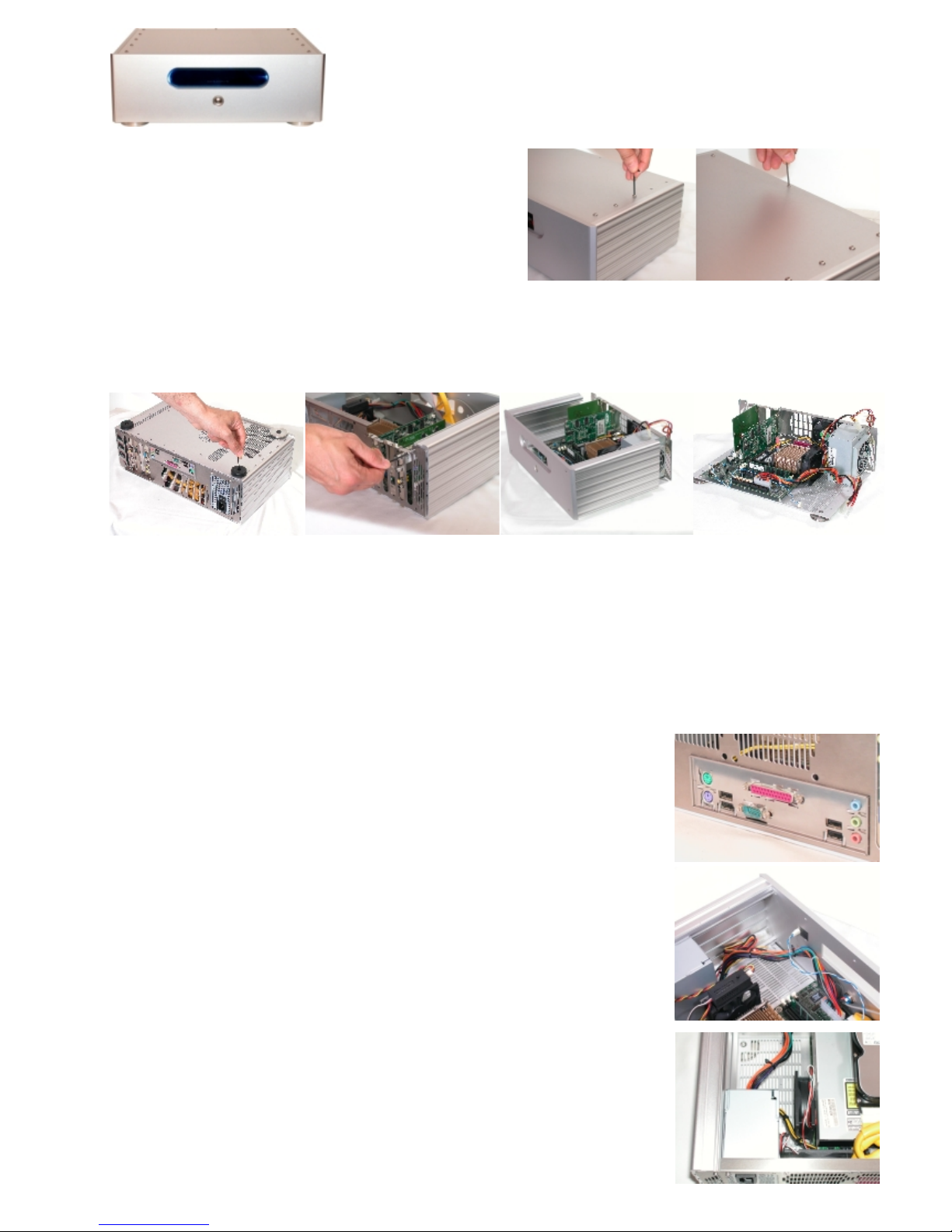
Remove the top lid by using the larger 2.5mm allen key on the 10
button head screws and use the 2mm allen key on the rear smaller
button head screw. Place these in a safe place noting where they
have come from. Now slide the lid back and up to expose the
inside.
RECOMMENDED BUILD PROCESS
Motherboard
connections cover in place
Whilst it is possible to populate the case with the PC components at this stage it is recommended that the sides and front fascia
are detached as a unit from the bottom and rear chassis. This allows better access during the build process and testing of the PC
components prior to full assembly.
1. Carefully turn the case over so the bottom is exposed, do this on soft surface which will not damage the case. Remove the six
screws from the base, two of which hold the rear feet in place. Place in a safe place and note where they have come from. The
front stainless steel feet DO NOT need to be removed, these can be left attached to the base plate.
2. Rear panel removal - remove the four outermost rear cap head screws with the 2.5mm allen key.
3. The front and sides can now be slid carefully away from the chassis and stored in a safe place.
1.
2.
3.
Populating chassis:
Refer to your motherboards handbook and place the stainless steel motherboard cover into the rectangular slot cut inside the
rear skin see pic. As instructed in motherboard handbook insert the CPU and install the
CPU heatsink. (For recommended heatsinks contact Stands Unique). Install recommended
memory as per handbook instructions.
Place motherboard connection panel (supplied with motherboard) into rectangular cutout in
Claritas rear panel.
Carefully align your motherboard over the spacer pillars on the bottom chassis taking care
to feed the motherboard connections through the rear access panel. Use the M3 button
head screws supplied with the 2mm allen key to secure the motherboard.
Remove the stainless steel clamping strip from the top of the rear panel over the PC slots
using the smaller 2mm allen key. Install your AGP graphics card if required as per the
graphics card handbook.
Install any other PCI cards as per instructions provided with each card.
Cooling Fan - IT IS VERY IMPORTANT THE FAN IS MOUNTED AS SHOWN.
Locating the fan:
The chassis must be carefully moved to an upright position as shown in the picture ensuring
maximum distance from power supply to rear of fan - the fan must be blowing air onto the
heatsink.
(a fan speed controller is recommended in-between the motherboard connection and fan
connection - such as Zalman Fanmate or equivalent ensuring optimised fan speed/noise ratio.)
These are available form Stands Unique.
For more powerful processors P4 2.6Ghz and above then an 80mm chassis fan may be
required to pull warm air out of the case, a fan controller is recommended to keep noise to an
absolute minimum.
Populate

At this stage you can decide to either attached the sides and fascia to the base and back to
complete the build of the case, or alternatively we recommend configuring the PC by
connecting the peripherals (hard disc /optical drive DVD or CD-RW etc.) and booting up to
check the system p.o.s.t.s . Fully installing your operating system is now recommended.
Note: to switch the system on without the front fascia switch, this is possible by shorting the
‘on/off’ pins on the motherboard for a fraction of a second as shown in the motherboard
handbook.
Once everything is configured switch off and disconnect the peripherals leaving the cables on
the motherboard.
Mounting the Optical drive in the enclosure:
Remove the pair of internal brackets on the rear of the fascia. see pic.
Bring together the Claritas housing and chassis by reversing the steps 1-3.
Ensure the IDE hard drive, optical drive / serial ATA cables are in place.
Ensure the l.e.d. ‘power on’ light is attached to the motherboard ‘power on’ pins and attached
to the l.e.d. on the rear of the fascia.
Ensure the ‘power switch’ cable is attached on the motherboard pins.
Replace clamping strip over the top of the PC cards using the smaller 2mm allen key with the
3mm button head screws.
Attaching the optical drive:
Attach optical drive to the brackets (see pic) taking care to ensure the front of the drive is
aligned to the front of the bracket. Now insert the optical drive by using the four M4 x 6mm
allen screws with the larger 2.5mm allen key. Now attach power cable and ribbon cable the
red stripe on the ribbon cable should be next to the power connector.
Attaching the hard disc:
Place the hard disc on top of the optical drive either to the left or right (recommend left) and
use two of the 6-32 Philips head screws to secure the drive. see pic. Now attach power and
ribbon cable.
For more info on finishes and availability contact Rod Keith at Stands Unique on 01933 412227 email: claritas@standsunique.com
please note some detail on pictures may be different on production items
Stands Unique reserve the right to change specifications without prior notice due to continued product improvement and development.
Attaching the optical drive cover
Use the supplied double sided sticky pads to attach the drawer cover to the front of the optical
drive tray. Note that the drive tray front attached to the tray is easily removable by gently
pulling the bottom part forward and at the same time pushing it upwards.
The drawer cover should be adhered so there is a even concentric gap all the way round the
outside. Placing the Claritas on its rear should make this easier to ‘eye up’.
Optical drives do vary in design of the front panel and tray cover so check how many pads are
required prior to fixing the cover. The pads should just be proud of the fascia front for them to
work efficiently and enable the edgelight effect to work at its best.
Start your computer and eject the drive using your operating software. (tip: In Windows a right
click on the drive icon will achieve this.)
Once the tray is open one of the supplied silicon buffer pads is used to mate with the eject
button on the optical drive, again Fix this to the rear of the
drawer cover as shown. A simple light push to the bottom portion of the drawer cover then
manually ejects the tray from the drive.
Now you are ready to use your computer. A silicon based spray polish is recommended for
cleaning the enclosure such as Pledge.
check which thickness is ideal.
 Loading...