


USA:
+1 866.782.6339
|
salesusa@standexmeder.com
EMEA:
+49 7731/8399-0
|
info@standexmeder.com
APAC:
+86 21/37606000
|
salesasia@standexmeder.com
standexelectronics.com
Series Datasheet
Version 02
28
Feb 2019
Page
M.
Reizner
1
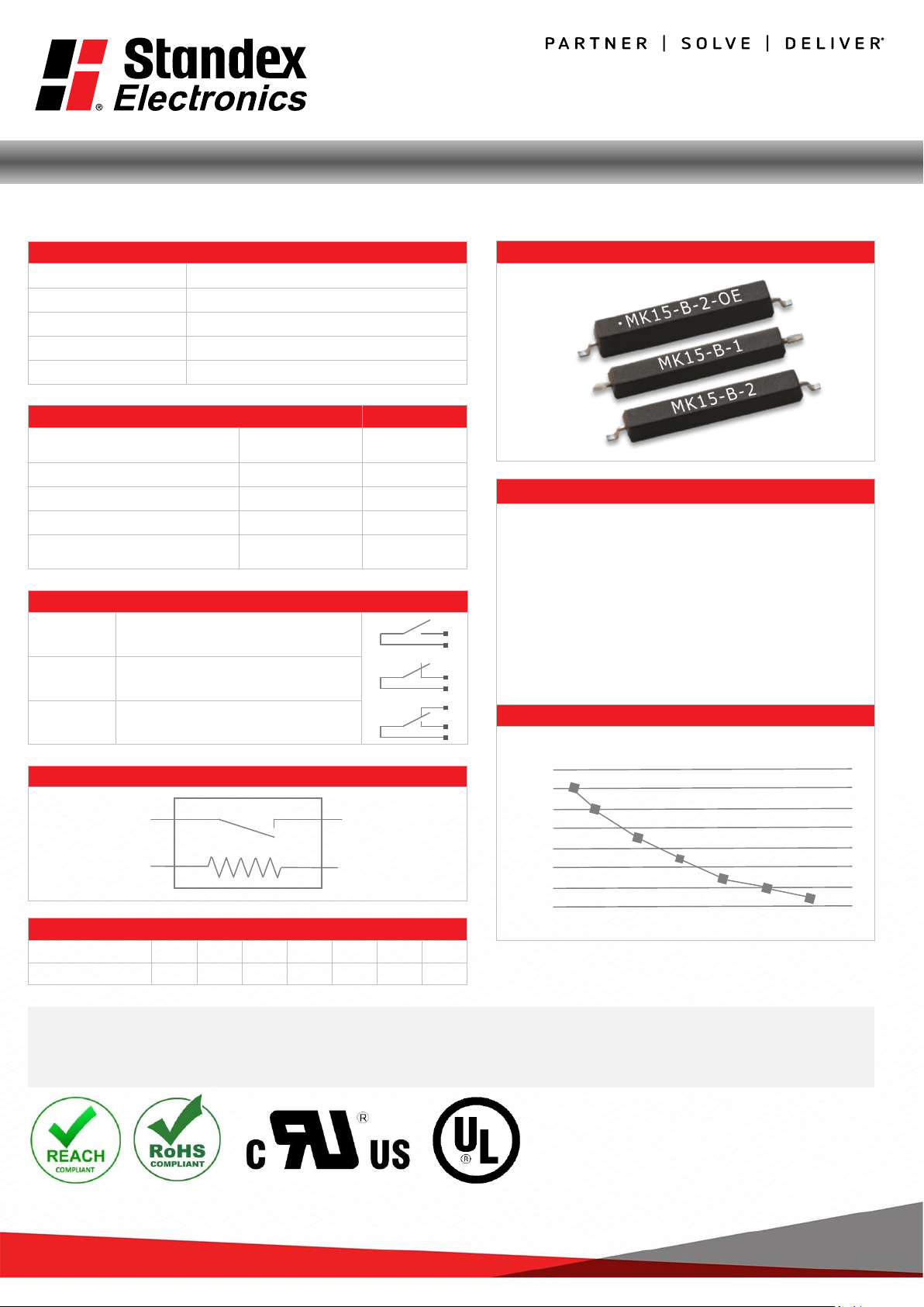
MK15 Series Reed Sensors
➢ Features: Supplied in Tape & Reel, Excellent for Low Power
Operations
➢ Applications: On/Off Control Switch, Position Detection,
Switching Element & Others
➢ Markets: Appliance, Telecommunication, Security, Medical
& Others
Part
Description: MK15- X - 0
Magnetic Sensitivity Lead Design
B, C, D, E, F, G 1, 2
Customer
Options Switch Model
Unit
Contact Data
66
Rated Power (max.)
Any DC combination of V&A not to exceed their individual max.’s
10 W
Switching Voltage (max.)
DC or peak AC
180 V
Switching Current (max.)
DC or peak AC
0.5 A
Carry Current (max.)
DC or peak AC
1.0 A
Contact Resistance (max.)
@ 0.5V & 50mA
150 mOhm
Breakdown
Voltage (min.)
According
to EN60255-5
0.2 kVDC
Operating Time (max.)
Incl. Bounce; Measured with w/ Nominal Voltage
0.5 ms
Release Time (max.)
Measured
with no Coil Excitation
0.05 ms
Insulation
Resistance (typ.)
Rh<45%, 100V Test
Voltage
10
10
Ohm
Capacitance
(typ.)
@ 10kHz
across open Switch
0.3 pF
USA:
+1 866.782.6339
|
salesusa@standexmeder.com
EMEA:
+49 7731/8399-0
|
info@standexmeder.com
APAC:
+86 21/37606000
|
salesasia@standexmeder.com
standexelectronics.com
Series Datasheet
Version 02
28
Feb 2019
Page
M.
Reizner
2
MK15 Series Reed Sensors
MK15 Reed Sensor
Housing and Lead Specifications
Housing Material Mineral Filled Epoxy
Case Color Black
Lead design 1 Flat, straight leads for PCB slot mounting
Lead design 2 Flat, bent SMD leads
Layout
Top View
Glossary Contact Form
Form A
NO = Normally Open Contacts
SPST = Single Pole Single Throw
Form B
NC = Normally Closed Contacts
SPST = Single Pole Single Throw
Form C
Changeover
SPDT = Single Pole Double Throw
Please note: All technical specifications on this series datasheet refer to the standard product range. Modifications in the sense of technical progress are reserved. For
general information only. For more specific information, please consult the product datasheet, available upon request.
This series datasheet could contain technical inaccuracies or typographical errors. Changes are periodically made to the information herein. These change will be
incorporated in future revisions.
For deviating values, most current specifications and products please contact your nearest sales office.
Glossary Magnetic Sensitivity
Sens. A B C D E F G
AT
05-10
10-15
15-20
20-25
25-30
30-35
35-40
Environmental Data
Unit
Shock Resistance (max.)
1/2 sine wave duration 11ms
30 g
Vibration Resistance (max.)
20
g
Operating Temperature
-40 to 130
°C
Storage Temperature
-50 to 130 °C
Soldering Temperature (max.)
5 sec. max.
260
°C
Handling & Assembly Instructions
➢ Use proper lead clamping or heat sinking techniques to
prevent mechanical and/or heat stress during,
soldering, and welding
➢
Mechanical shock as the result of dropping the reed
sensor typically from a distance of greater than 12”
may change it’s magnetic sensitivity and/or destroy the
sensor
➢
Reflow Soldering Conditions according to JEDEC norm
J-STD-020D.1
Life Test Data
*Load increase reduces life expectancy of Reed Switches
Load
Life time
 Loading...