

Page 1

SINGLE MOTOR
ASSEMBLY
MANUAL
F2 - SM - TS
Page 2
VIDEO ASSEMBLY GUIDE
CAUTION / INFORMATION
!
Make sure there are no obstacles in the desk’s path. Make sure the desktop is not touching any walls.
!
!
Make sure all cords are the appropriate length in order to accommodate the change in height of your desk.
!
Keep children away from fully electric standing desks, control boxes, and controllers. There is a risk of injury or electric shock.
!
Keep all electrical components away from liquids.
!
Do not sit, stand, crawl, or lie on or under the StandDesk.
!
Do not place any objects taller than 20" underneath the StandDesk.
!
Do not open any of the inner components - Legs, Control Box, Controller. There is a risk of injury or electric shock.
This product is designed with a duty cycle of 10% (2 min. on & 18 min. off).
I
www.standdesk.co/pages/faq
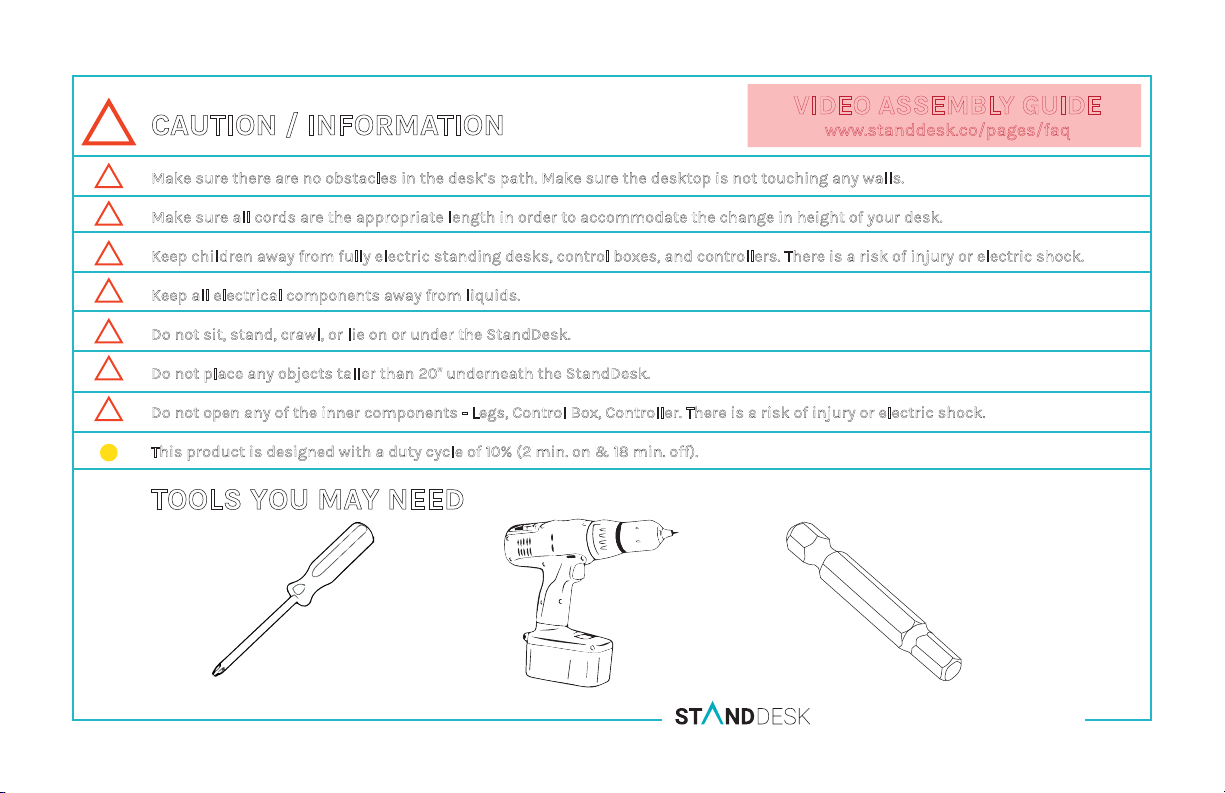
TOOLS YOU MAY NEED
Philip’s Head Screwdriver
Power Drill
5mm Allen Bit
SINGLE MOTOR ASSEMBLY MANUAL F2-SM-TS
Page 3
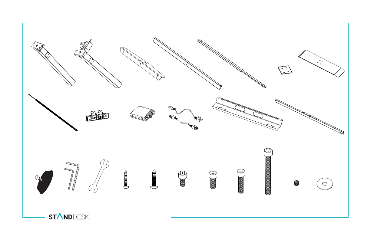
PARTS
1. Leg without Motor
8. Drive Shaft plus Rod
2. Leg with Motor
HARDWARE
Drive Shaft
Tool
Allen
Wrenches
3. Support Brace x2
9. Handset
Open Wrench
SINGLE MOTOR ASSEMBLY MANUAL F2-SM-TS
10. Control Box
M3.5x19 x2
M4.8x19 x8 M6x12 x12 M6x16 x10 M6x25 x6 M6x55 x4 M5x5 x4 Washers x4
4. Back Middle Slat
11. Power Cords x2
5. Front Middle
Slat
12. Cable Management Tray (optional)
6. Stabilizing
Foot Plate x2
7. Feet x2
13. Crossbar (optional)
Page 4
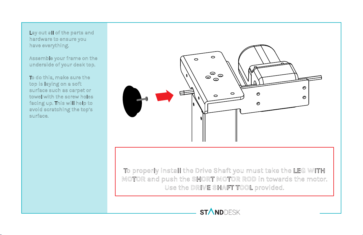
Lay out all of the parts and
hardware to ensure you
have everything.
Assemble your frame on the
underside of your desk top.
To do this, make sure the
top is laying on a soft
surface such as carpet or
towel with the screw holes
facing up. This will help to
avoid scratching the top’s
surface.
IMPORTANT
To properly install the Drive Shaft you must take the LEG WITH
MOTOR and push the SHORT MOTOR ROD in towards the motor.
Use the DRIVE SHAFT TOOL provided.
DUAL MOTOR ASSEMBLY MANUAL F2-SM-TS
Page 5
A.
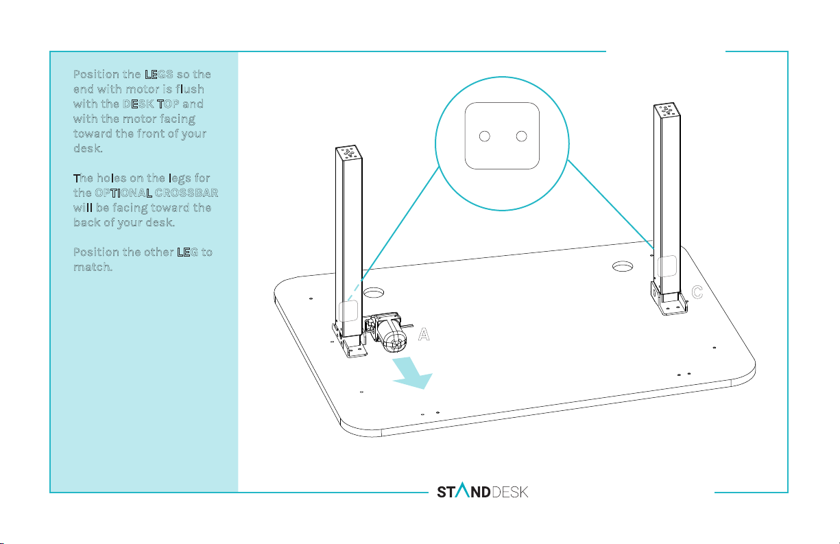
Position the LEGS so the
end with motor is flush
with the DESK TOP and
with the motor facing
toward the front of your
desk.
B.
The holes on the legs for
the OPTIONAL CROSSBAR
will be facing toward the
back of your desk.
C.
Position the other LEG to
match.
STEP ONE
BACK
B
holes for OPTIONAL
CROSSBAR
C
A
SINGLE MOTOR ASSEMBLY MANUAL F2-SM-TS
Page 6
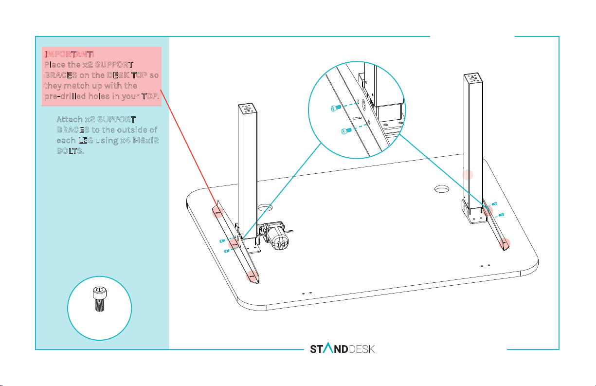
IMPORTANT!
Place the
BRACES on the DESK TOP so
they match up with the
pre-drilled holes in your TOP.
A.
x2 SUPPORT
Attach x2 SUPPORT
BRACES to the outside of
each LEG using x4 M6x12
BOLTS.
STEP TWO
x4 M6x12
SINGLE MOTOR ASSEMBLY MANUAL F2-SM-TS
Page 7
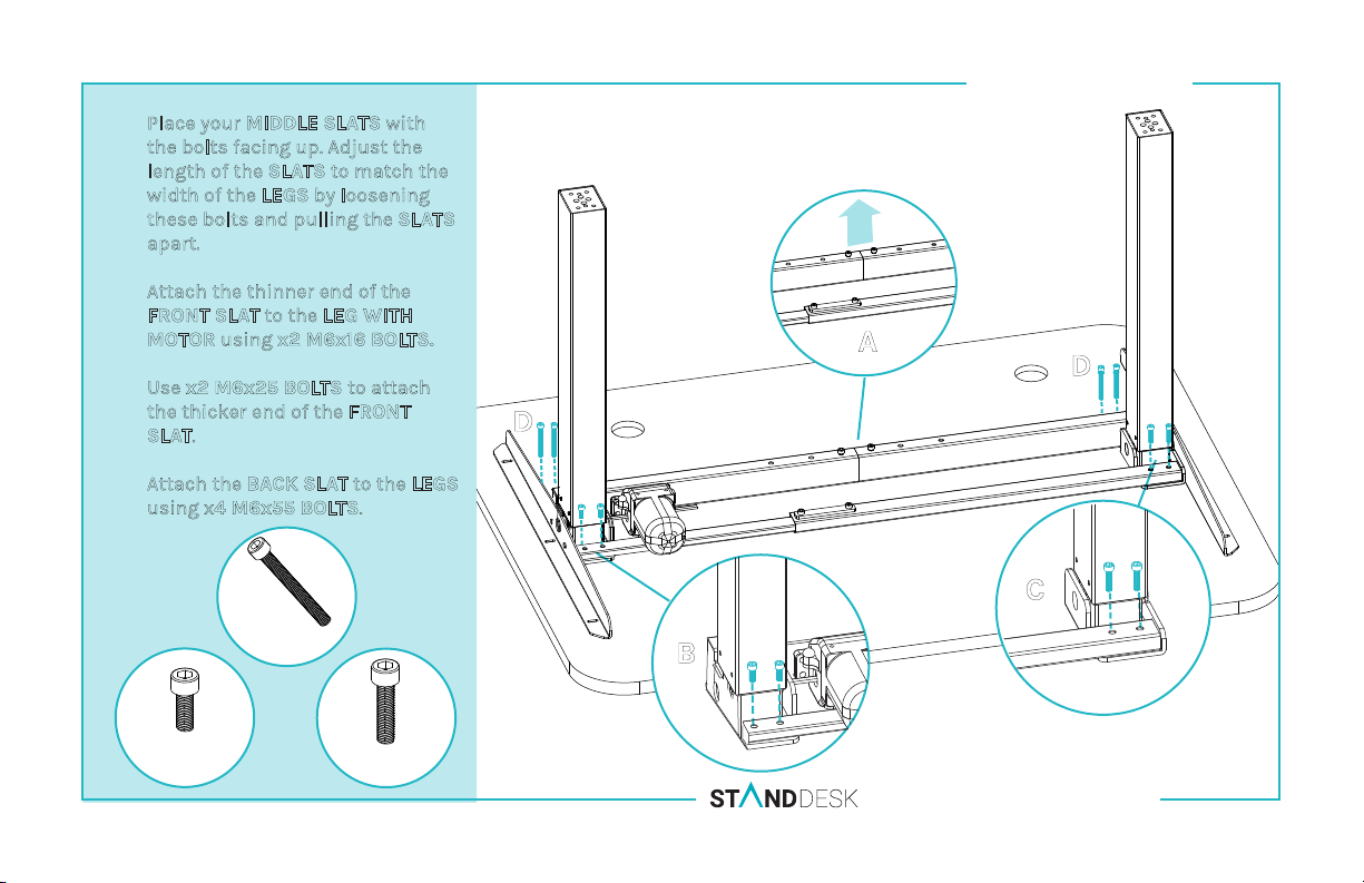
A.
Place your MIDDLE SLATS with
the bolts facing up. Adjust the
length of the SLATS to match the
width of the LEGS by loosening
these bolts and pulling the SLATS
apart.
Attach the thinner end of the
B.
FRONT SLAT to the LEG WITH
MOTOR using x2 M6x16 BOLTS.
C.
Use x2 M6x25 BOLTS to attach
the thicker end of the FRONT
SLAT.
D.
Attach the BACK SLAT to the LEGS
using x4 M6x55 BOLTS.
STEP THREE
A
D
D
x2
M6x16
x4
M6x55
C
B
x2
M6x25
SINGLE MOTOR ASSEMBLY MANUAL F2-SM-TS
Page 8
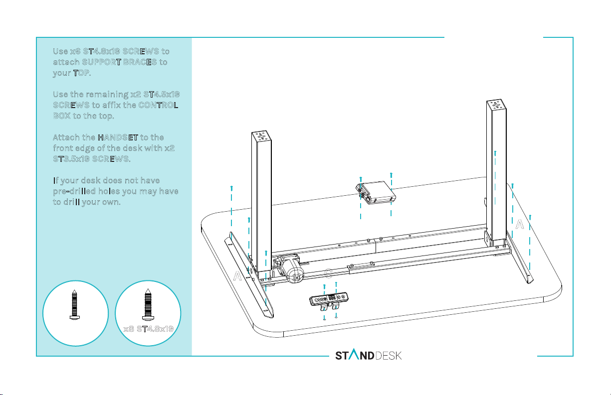
A.
Use x6 ST4.8x19 SCREWS to
attach SUPPORT BRACES to
your TOP.
Use the remaining x2 ST4.5x19
B.
SCREWS to affix the CONTROL
BOX to the top.
Attach the HANDSET to the
C.
front edge of the desk with x2
ST3.5x19 SCREWS.
If your desk does not have
*
pre-drilled holes you may have
to drill your own.
STEP FOUR
B
A
x2 ST3.5x19
x8 ST4.8x19
A
C
SINGLE MOTOR ASSEMBLY MANUAL F2-SM-TS
Page 9
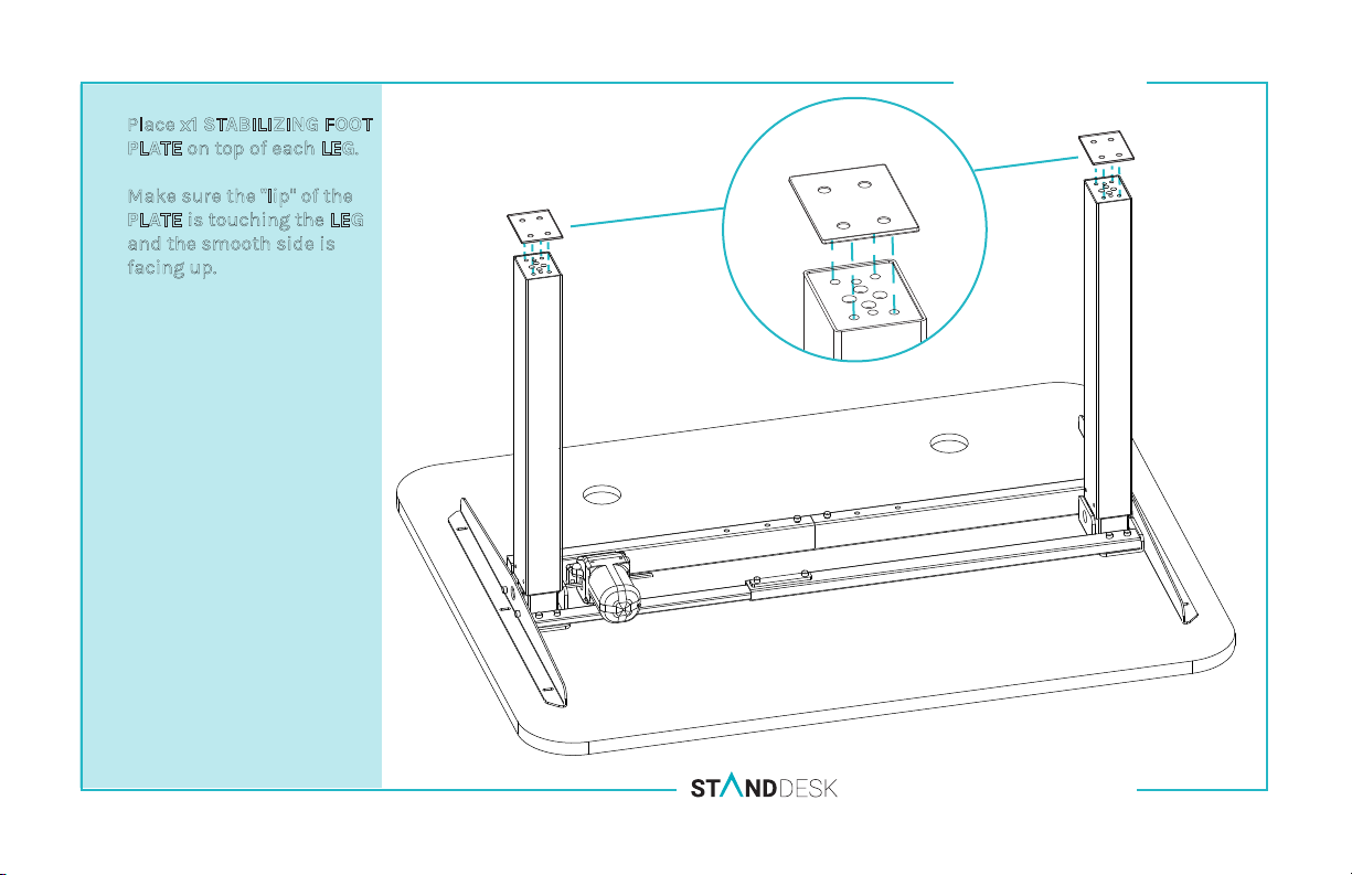
Place x1 STABILIZING FOOT
A.
PLATE on top of each LEG.
Make sure the "lip" of the
*
PLATE is touching the LEG
and the smooth side is
facing up.
STEP FIVE
SINGLE MOTOR ASSEMBLY MANUAL F2-SM-TS
Page 10
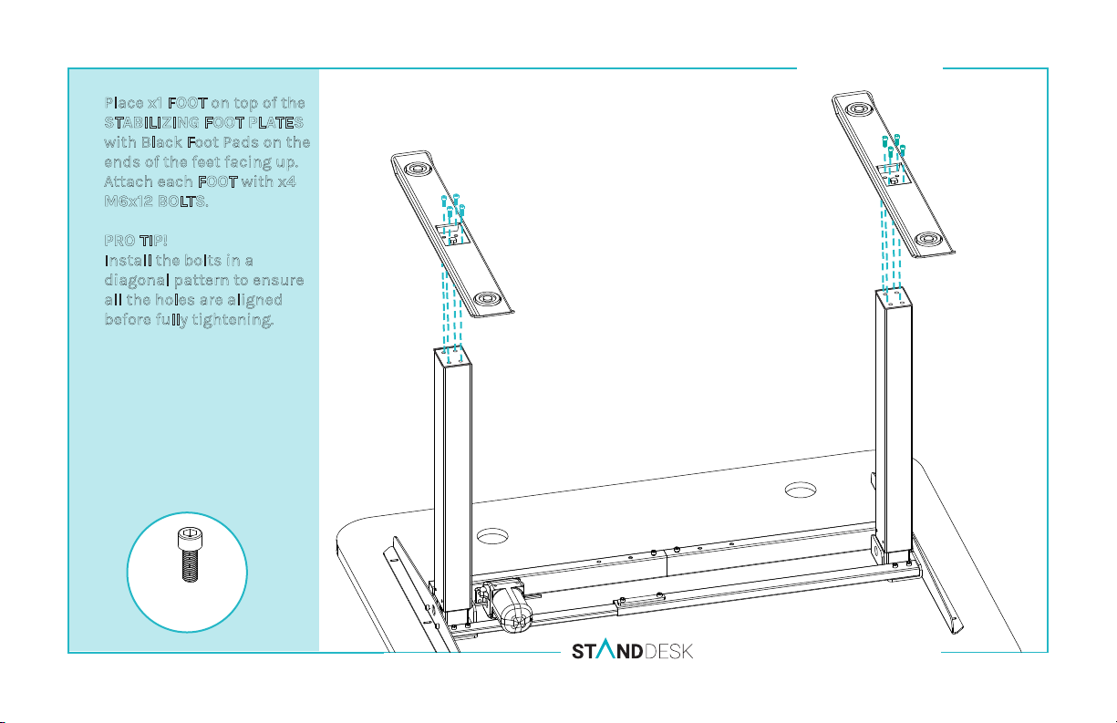
Place x1 FOOT on top of the
A.
STABILIZING FOOT PLATES
with Black Foot Pads on the
ends of the feet facing up.
Attach each FOOT with x4
M6x12 BOLTS.
PRO TIP!
Install the bolts in a
diagonal pattern to ensure
all the holes are aligned
before fully tightening.
STEP SIX
x8 M6x16
SINGLE MOTOR ASSEMBLY MANUAL F2-SM-TS
Page 11
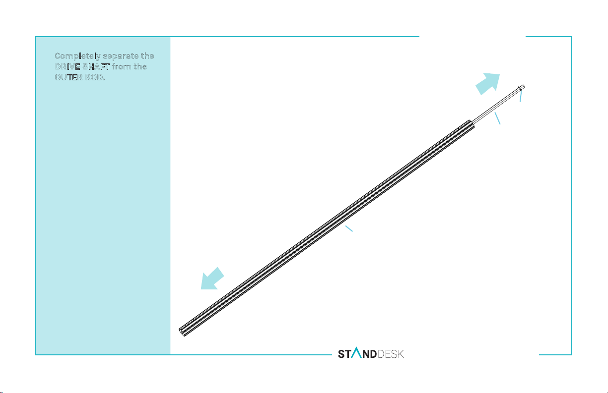
Completely separate the
A.
DRIVE SHAFT from the
OUTER ROD.
STEP SEVEN
C-Clamp
Drive Shaft
Outer Rod
SINGLE MOTOR ASSEMBLY MANUAL F2-SM-TS
Page 12
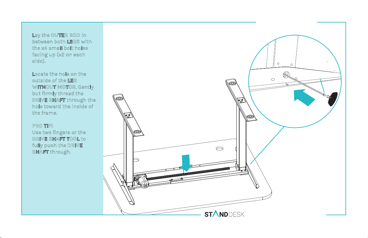
Lay the OUTER ROD in
A.
between both LEGS with
the x4 small bolt holes
facing up (x2 on each
side).
Locate the hole on the
B.
outside of the LEG
WITHOUT MOTOR. Gently
but firmly thread the
DRIVE SHAFT
hole toward the inside of
the frame.
PRO TIP!
Use two fingers or the
DRIVE SHAFT TOOL to
fully push the DRIVE
SHAFT through.
through the
STEP EIGHT
C-Clamp
B
A
SINGLE MOTOR ASSEMBLY MANUAL F2-SM-TS
Page 13
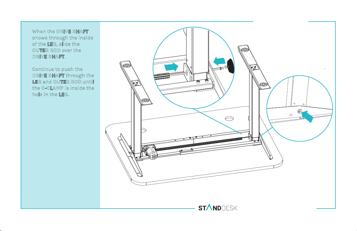
A.
When the
shows through the inside
of the LEG, slide the
OUTER ROD over the
DRIVE SHAFT.
B.
Continue to push the
DRIVE SHAFT through the
LEG and OUTER ROD until
the C-CLAMP is inside the
hole in the LEG.
DRIVE SHAFT
STEP NINE
A
B
SINGLE MOTOR ASSEMBLY MANUAL F2-SM-TS
Page 14
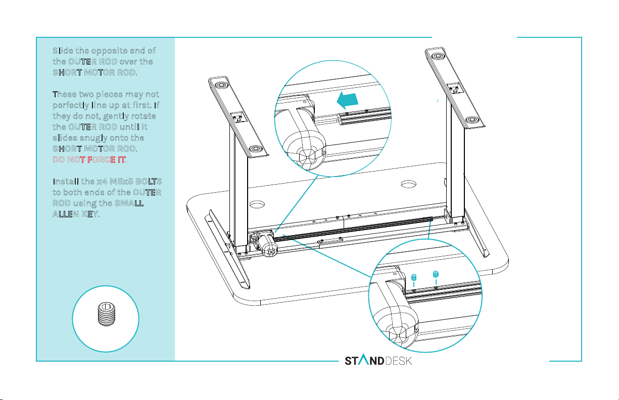
Slide the opposite end of
A.
the OUTER ROD over the
SHORT MOTOR ROD.
These two pieces may not
*
perfectly line up at first. If
they do not, gently rotate
the OUTER ROD until it
slides snugly onto the
SHORT MOTOR ROD.
DO NOT FORCE IT.
Install the x4 M5x5 BOLTS
B.
to both ends of the
ROD using the SMALL
ALLEN KEY.
OUTER
STEP TEN
A
B
x4 M5x5
SINGLE MOTOR ASSEMBLY MANUAL F2-SM-TS
Page 15
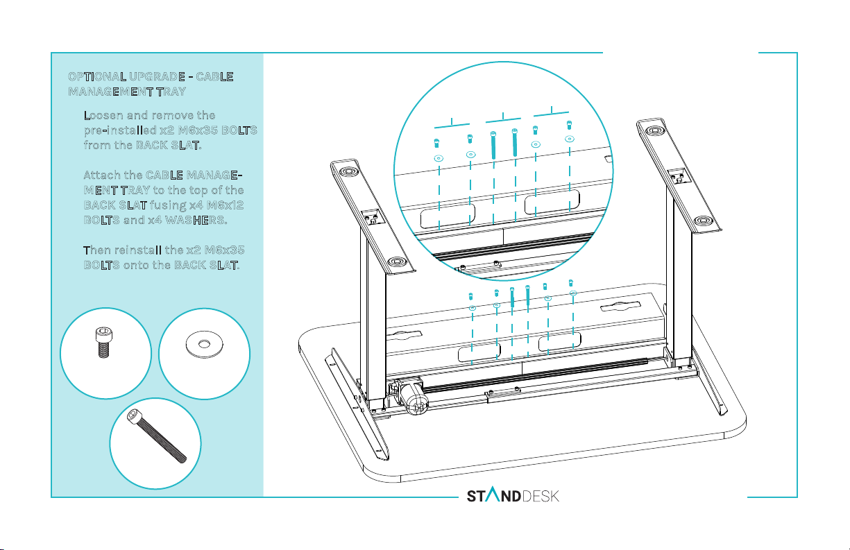
OPTIONAL UPGRADE - CABLE
MANAGEMENT TRAY
Loosen and remove the
A.
pre-installed x2 M6x35 BOLTS
from the
Attach the CABLE MANAGE-
B.
MENT TRAY to the top of the
BACK SLAT fusing x4 M6x12
BOLTS and x4 WASHERS.
Then reinstall the x2 M6x35
BOLTS onto the BACK SLAT.
BACK SLAT.
B
A
STEP ELEVEN
B
x4 M6x12
x4 Washers
x2 M6x35
SINGLE MOTOR ASSEMBLY MANUAL F2-SM-TS
Page 16
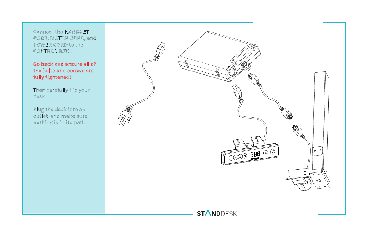
A.
Connect the HANDSET
CORD, MOTOR CORD, and
POWER CORD to the
CONTROL BOX .
Go back and ensure all of
B.
the bolts and screws are
fully tightened!
Then carefully flip your
C.
desk.
D.
Plug the desk into an
outlet, and make sure
nothing is in its path.
STEP TWELVE
SINGLE MOTOR ASSEMBLY MANUAL F2-SM-TS
Page 17
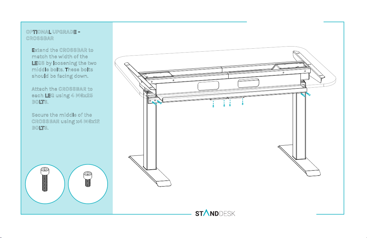
OPTIONAL UPGRADE CROSSBAR
Extend the CROSSBAR to
A.
match the width of the
LEGS by loosening the two
middle bolts. These bolts
should be facing down.
Attach the CROSSBAR to
B.
each LEG using 4 M6x25
BOLTS.
C.
Secure the middle of the
CROSSBAR using x4 M6x12
BOLTS.
STEP THIRTEEN
B
B
C
x4 M6x25
x4 M6x12
SINGLE MOTOR ASSEMBLY MANUAL F2-SM-TS
Page 18
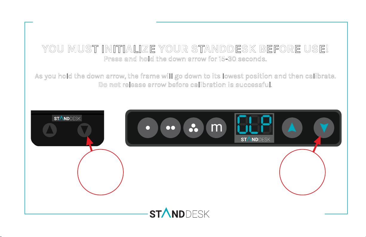
INITIALIZING YOUR STANDDESK
YOU MUST INITIALIZE YOUR STANDDESK BEFORE USE!
Press and hold the down arrow for 15-30 seconds.
As you hold the down arrow, the frame will go down to its lowest position and then calibrate.
Do not release arrow before calibration is successful.
OR
PRESS
AND HOLD
15-30 SEC
DUAL MOTOR ASSEMBLY MANUAL F2-SM-TS
PRESS
AND HOLD
15-30 SEC
Page 19
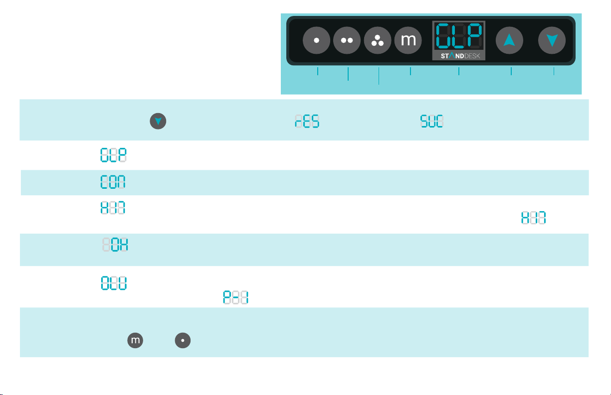
MEMORY HANDSET
MANUAL
Wake:
To wake press any buon.
Seng One
Seng Two
Seng Three
Menu
LED Display
Up Arrow
Down Arrow
Calibrate
or Reset:
GLP:
CON:
HIT:
OH:
OLU:
Set
Preferred
Heights:
PRESS/HOLD LED Display shows 15 seconds
stands for Go to Lowest Posion. This means your desk must be re-calibrated.
stands for Connecon. One of the frame legs are not working properly. Unplug the device and plug it back in.
stands for HIT. This protects your desk against collisions that could lead to damage.
if something hits your frame while it is raising or lowering, it will automacally stop and Memory Handset will read
stands for Overheat. This will show up if the desk has had two minutes of constant usage. To resolve, wait 15 minutes for
your desk to cool down.
stands for Overload, this means there is too much weight on your frame. Either remove some weight or change the load
capacity on your frame in seng
ADJUST to 1st preferred height
PRESS PRESS REPEAT steps for remaining settings.
HOLD until Display shows
RELEASE then Display shows 24.
Page 20
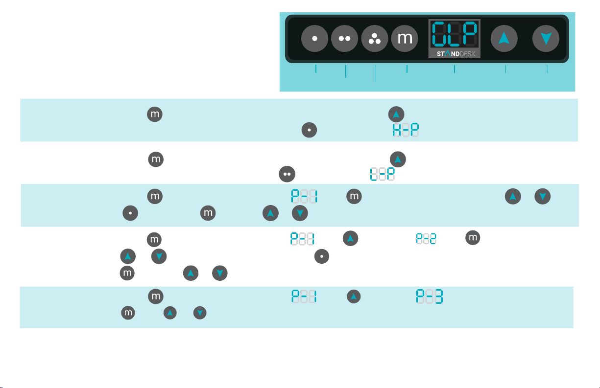
MEMORY HANDSET
MANUAL (CONTINUED)
Seng One
Seng Two
Seng Three
Menu
LED Display
Up Arrow
Down Arrow
Set Max
Height:
Set Min
Height:
Set Max/Min
Load Capacity:
Measurement
Conversion:
Collision
Sensivity:
PRESS/HOLD 15 seconds RELEASE WHEN LED Display blinks PRESS/HOLD
When desk raises to highest point (47) RELEASE PRESS LED Display shows
PRESS/HOLD 15 seconds
When desk reaches lowest point RELEASE PRESS
PRESS/HOLD PRESS
PRESS
PRESS/HOLD 20 seconds
PRESS OR
PRESS
PRESS/HOLD 20 seconds
PRESS
20 seconds
to exit or PRESS to choose a dierent (P) setting
then
PRESS OR to adjust sensitivity (5-30)
PRESS
to go from inches (1) and cm (0)
PRESS to choose a dierent (P) setting OR
RELEASE WHEN LED Display blinks PRESS/HOLD
LED Display shows
LED Display will show
then
LED Display will show
LED Display will show
OR
PRESS
PRESS to exit or
PRESS twice to show
15 is standard, lower the number the more sensitive.
ADJUST max/min load capacity using
once to show
OR
PRESS
 Loading...