

Page 1
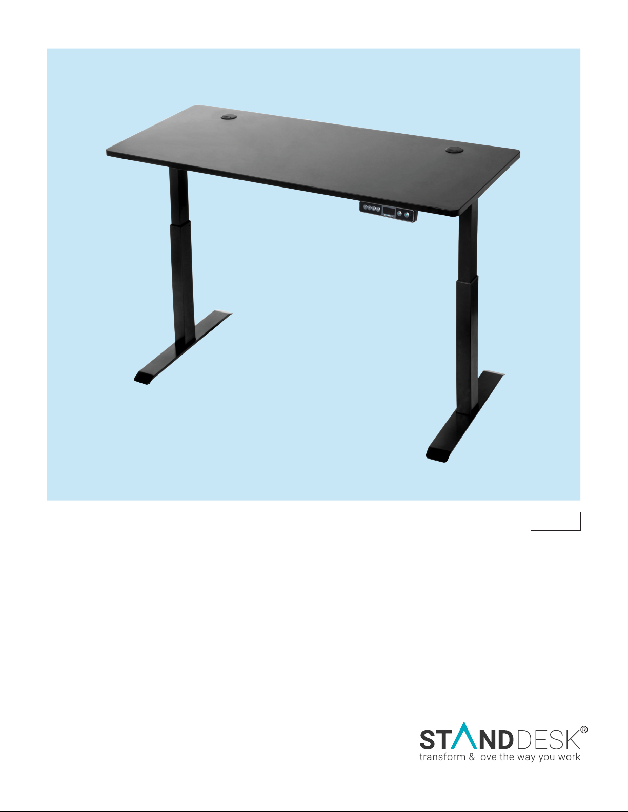
SIMPLE
ASSEMBLY MANUAL
Single Motor Dual Segment Frame
2017
Page 2
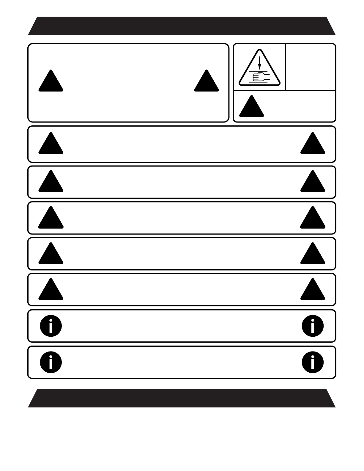
CAUTION/INFORMATION
Make sure no obstacles
around you are in the desk’s
path. Make sure the desktop is
not touching any walls. Make
sure all cords are appropriate
length to accommodate the
change in height.
Keep children away from electric height-adjustable desks,
control units and handsets. There is a risk of injury and
electric shock.
!!
WARNING
!
Pinch Point
Keep hands and
fingers clear
!!
Keep all electrical components away from liquids.
Do not sit, stand, crawl, or lie on or under the StandDesk.
Do not place any object taller than 20” underneath the
StandDesk
Do not open any of the components - the Legs, Control Box,
or Handset. There is a danger of electric shock.
This product is designed with a duty cycle of 10%
(2 min. on, 18 min. off)
!!
!!
!!
!!
In the event of a power outage or if the power cord is
unplugged, a manual reset may be necessary.
This StandDesk is height adjustable so that it can be positioned at the most
ergonomically suitable height. Any other use is at your risk.
Under no circumstances does StandDesk accept warranty claims or liability claims
for damages caused from improper use or handling of the desk frame.
USE / LIABILITY
Page 3

!
WATCH ASSEMBLY VIDEO
www.standdesk.co/pages/faq
CLICK ON
StandDesk Simple Assembly
HIGHLY RECOMMENDED
Page 4
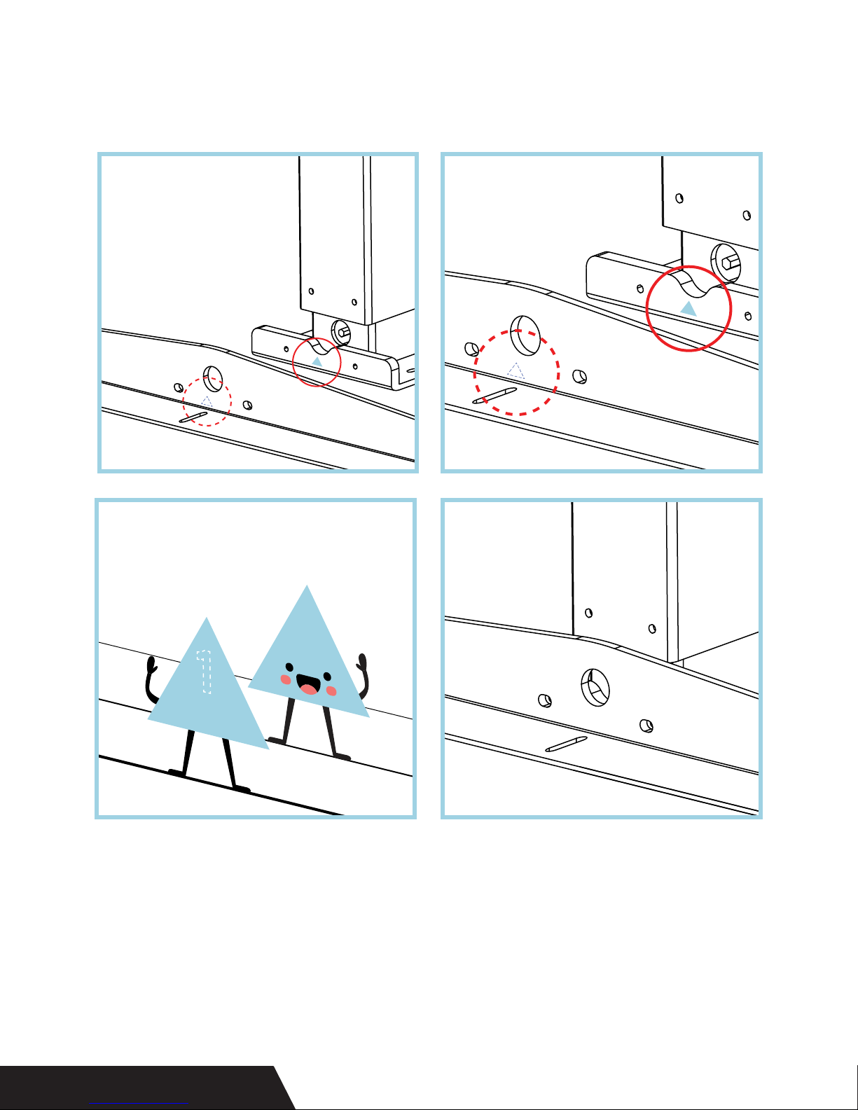
If you have the stickers, make sure their color and number
1
match up, like so.
PERFECT MATCH
Your desk might not have the sticker system to match up and
align parts. But not to worry, the assembly process is just the
same.
Now we’re ready to get familiar with all the pieces.
STICKER SYSTEM
Page 5
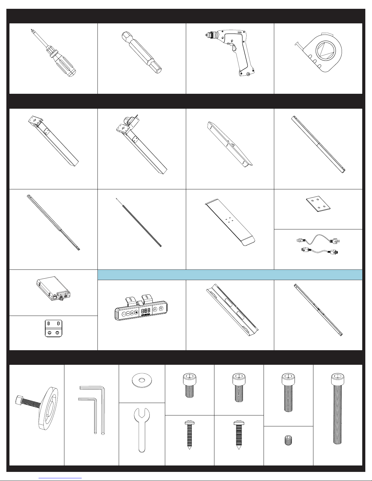
TOOLS REQUIRED
TOOLS
4mm Hex Bit (Optional)Phillips Head Screwdriver Power Drill (Optional) Tape Measure
COMPONENTS
P1
Leg without Motor Leg with Motor Support Braces (x2) Back Middle Slat
P5
P2 P3 P4
P6 P7 P8
Stabilizing Foot Plates (x2)
P9
Front Middle Slat
P10
Control Box
P11
Standard Handset
H1
Drive Shaft plus Rod Feet (x2)
P12 P13 P14
Memory Handset
(REPLACES STANDARD HANDSET IF ORDERED)
H2 H3
Washers (x4)
H4
OPTIONAL UPGRADES
Cable Management Tray Crossbar
HARDWARE
H8
M6x12 (x12)
H5 H6
H9 H10
M6x16 (x10)
M6x25 (x6)
H7
Power Cords (x2)
H11
Drive Shaft Tool
Open WrenchAllen Wrench (x2)
ST3.5x19 (x2)
ST4.8x19 (x8)
M5x5 (x4)
M6x55 (x4)
Page 6
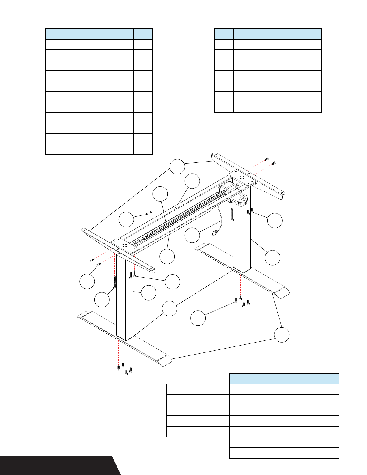
No.
Component Name
P1
Leg without Motor
P2
Leg with Motor
P3
Support Braces
Back Middle Slat
P4
Front Middle Slat
P5
P6
Drive Shaft plus Rod
Feet
P7
P8
Stabilizing Foot Plates
P9
Power Cords
Qty
1
1
2
1
1
1
2
2
2
No.
H5
H6
H7
H8
H9
H10
H11
Component Name
ST 3.5 x 19 Screws
ST 4.8 x 19 Screws
M5 x 5 Bolts
M6 x 12 Bolts
M6 x 16 Bolts
M6 x 25 Bolts
M6 x 55 Bolts
Qty
2
8
4
12
10
6
4
P10
P11
Control Box
Standard Handset
H8
H11
H7
1
1
P3
P4
P6
H9
P9
P5
H10
P2
P1
P8
H9
PARTS DIAGRAM
Height Range
Base Width
Travel Speed
Weight Capacity
Duty Cycle
P7
Specifications
26.4 in (67 cm) - 46 in (117 cm)
43 in (109 cm) - 58 in (147 cm)
1.01 in/sec (2.57 cm/sec)
308.6 lbs (140 kgs)
10% max. 2 mins on, 18 mins off
Soft start/stop
Adjustable leveling studs
Page 7
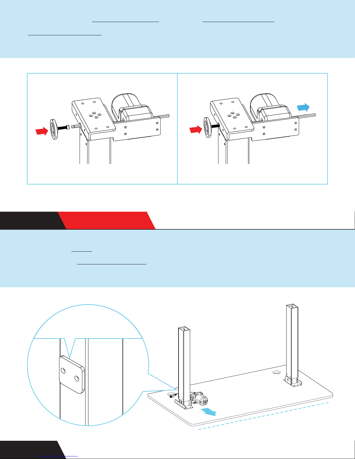
Start with the leg with motor. Use the drive shaft tool to push the
short motor rod that’s sticking out in toward the motor and all
the way through until it stops.
STEP 1 IMPORTANT
Place the legs upside down on the underside of your desktop.
Ensure the leg with motor is facing towards the front of your
desk, where you’ll be standing.
Crossbar
plates facing BACK
STEP 2
FRONT
Page 8
1
PRO TIP
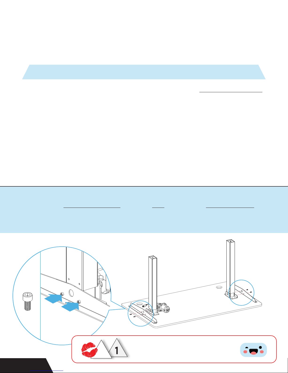
If you’re using a StandDesk top, place the support braces
on the desk so they line up with the pre-drilled holes. It’ll
make it easier for you later on.
Attach the support braces to each leg using four M6x12 bolts.
Ensure the flat side is touching the desktop.
H8
STEP 3
1
Match up the triangles so they kiss
1
!
Page 9
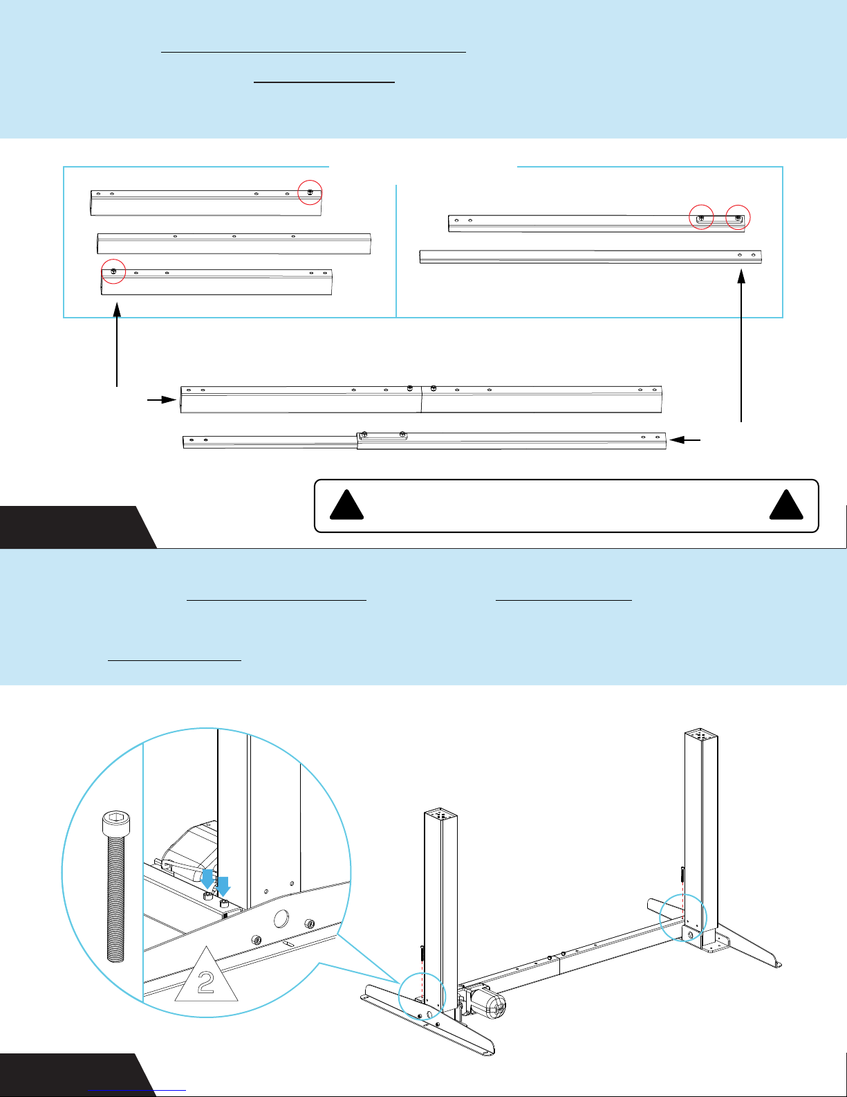
Find the front and back middle slats. Loosen but don’t remove
any pre-installed M6x12 bolts. Here’s what the two slats look like
in case they’re disassembled.
DISASSEMBLED
ASSEMBLED
BACK
FRONT
STEP 4
Attach the back middle slat using four M6x55 bolts. If you are
using a medium or large top, you will need to extend the width of
the middle slats.
H11
! !
The middle slat bolts may or may not be pre-installed.
2
STEP 5
Page 10
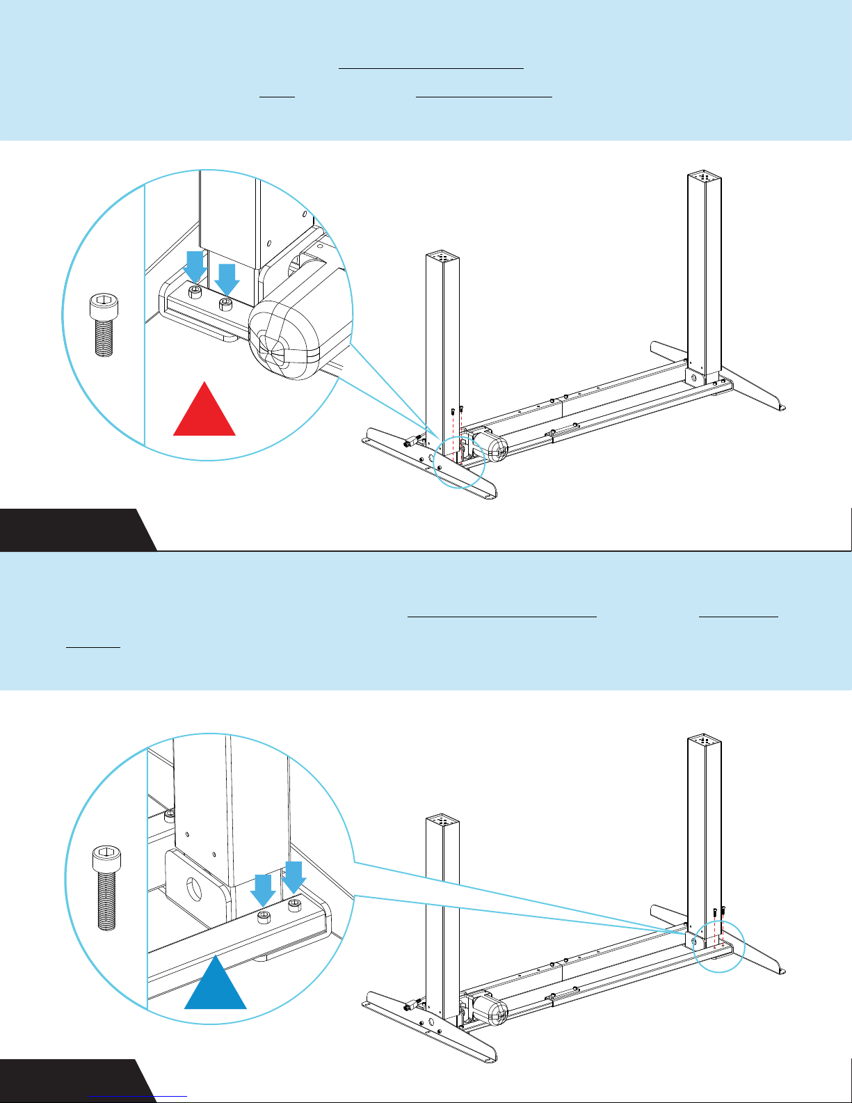
Slide the thin part of the front middle slat underneath the motor
and attach to the leg using two M6x16 bolts.
H9
2
STEP 6
Attach the opposite end of the front middle slat with two M6x25
bolts.
H10
2
STEP 7
Page 11
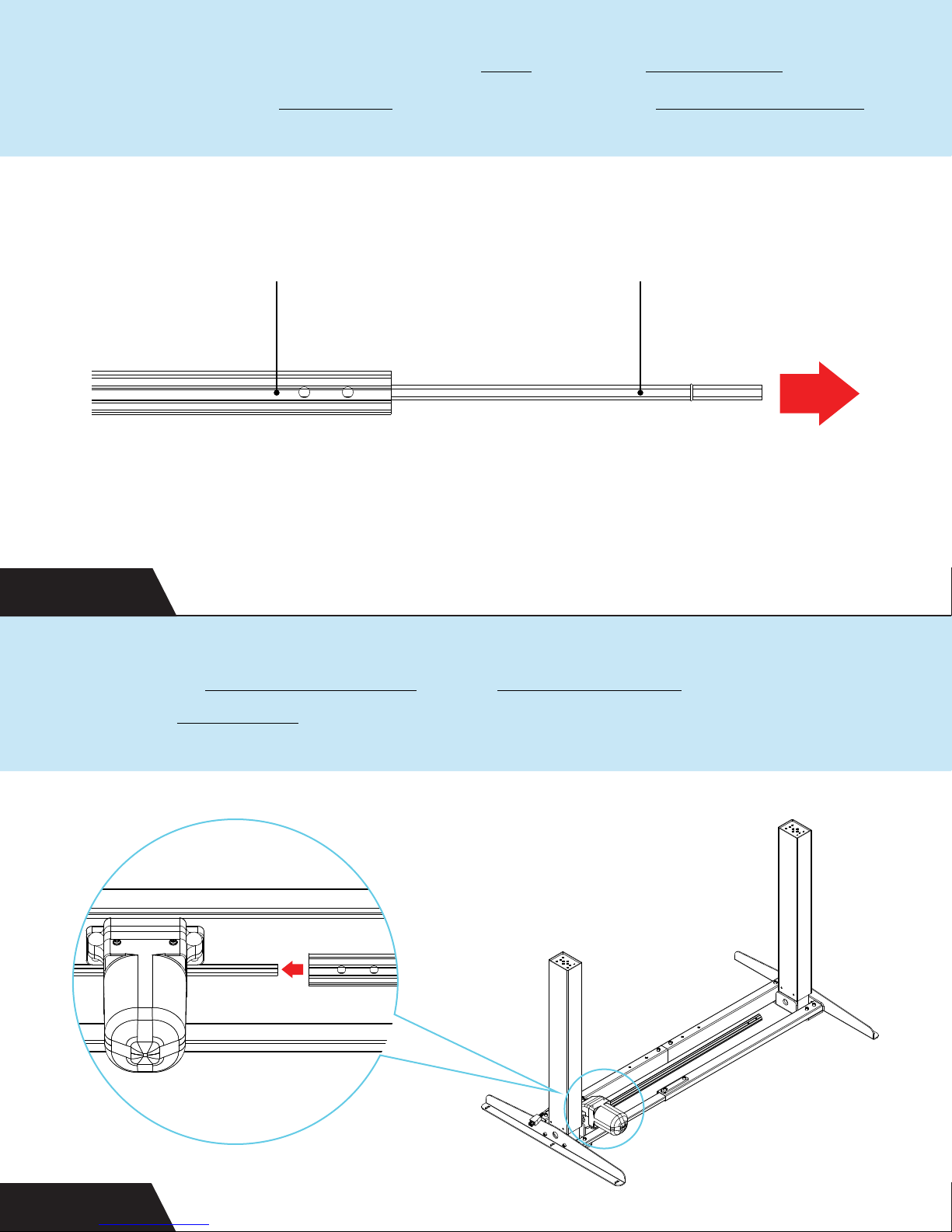
Now it’s time to connect the two legs with the drive shaft. Start
by removing the inner rod completely from the white drive shaft.
STEP 8
Attach the white drive shaft to the leg with motor by sliding it
over the motor rod.
DRIVE SHAFT
INNER ROD
STEP 9
Page 12
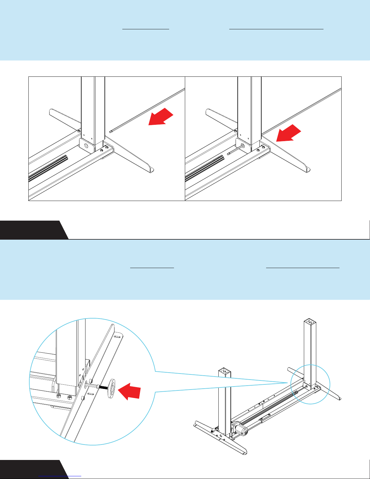
Carefully thread the inner rod through the leg without a motor. Be
gentle and use two fingers to align.
STEP 10
Continue to push the inner rod through, using the drive shaft tool
until it stops.
STEP 11
Page 13
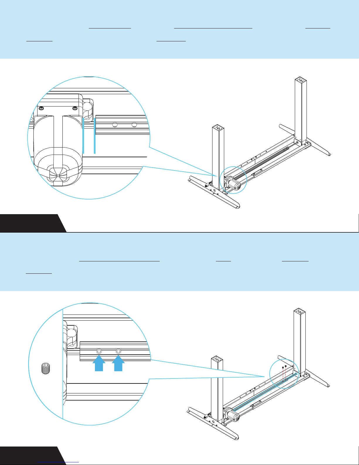
Now that the inner rod is in the white drive shaft, adjust the drive
shaft so it’s 1/2 inch off the motor.
1/2”
!
STEP 12
Secure the white drive shaft to the inner rod using two M5x5
bolts.
H7
STEP 13
Page 14
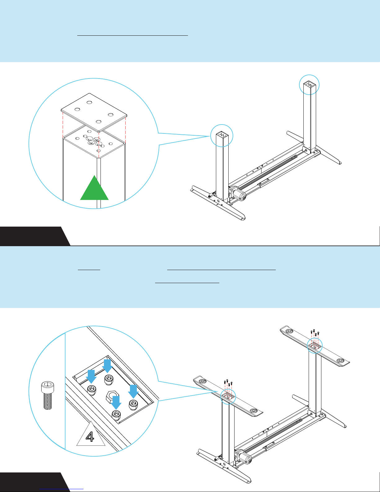
Place the stabilizing foot plates on top of each leg.
3
STEP 14
Place the feet on top of the stabilizing foot plates and align the
holes. Finger tighten four M6x16 bolts in a diagonal pattern for
best fit. Once all bolts are aligned, fully screw them in.
H9
4
STEP 15
Page 15
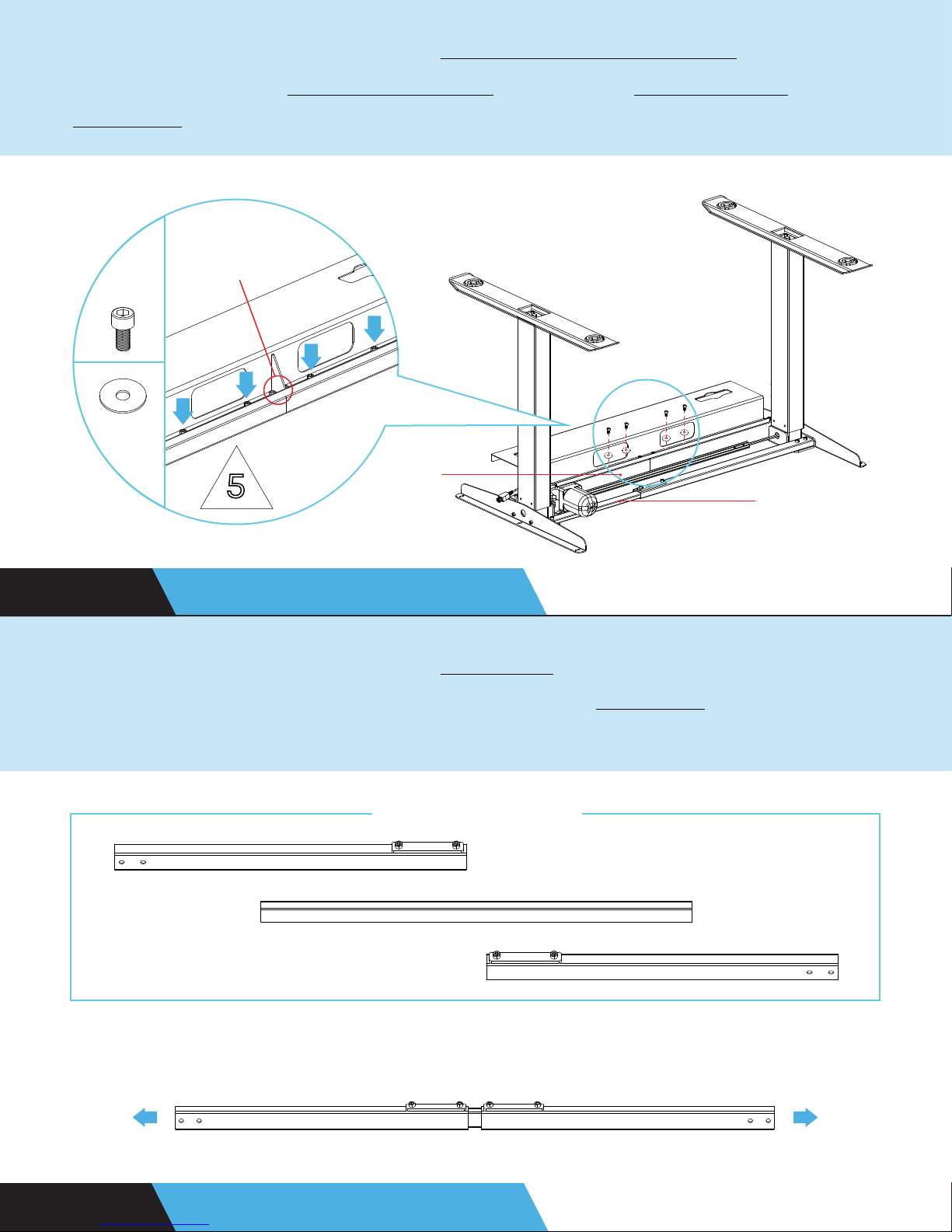
If you purchased the optional cable management tray, attach it
face down to the back middle slat using four M6x12 bolts and
washers.
M6x30 BOLTS
H8
H3
BACK
5
MIDDLE
SL AT
FRONT
MIDDLE
SL AT
STEP 16 OPTIONAL UPGRADE
If you purchased the optional crossbar, assemble it by loosening
the pre-installed bolts in the middle of the crossbar. Then, adjust
the width.
DISASSEMBLED
ASSEMBLED
! ! ! !
STEP 17 OPTIONAL UPGRADE
Page 16
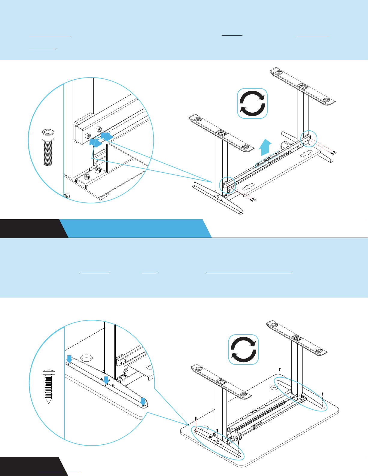
Ensure that the raised bolt holes are facing out. Attach the
crossbar to the holes on the back of the legs using four M6x25
bolts. Tighten the middle bolts once done.
H10
STEP 18 OPTIONAL UPGRADE
Attach the frame to the top using six ST 4.8x19 screws.
H6
STEP 19
Page 17
PRO TIP
If your top does not have pre-drilled holes, you can use a
drill or a power tool to attach your top. Here’s a separate
video to help you out.
http://bit.ly/standdesktop
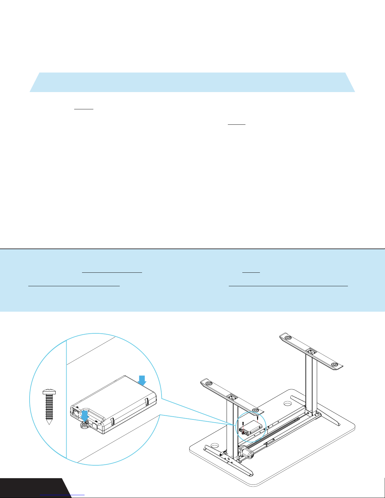
Attach the control box to the middle of the top using two
ST 4.8x19 screws. It can also sit on the cable management tray
if you upgraded to one.
H6
STEP 20
Page 18
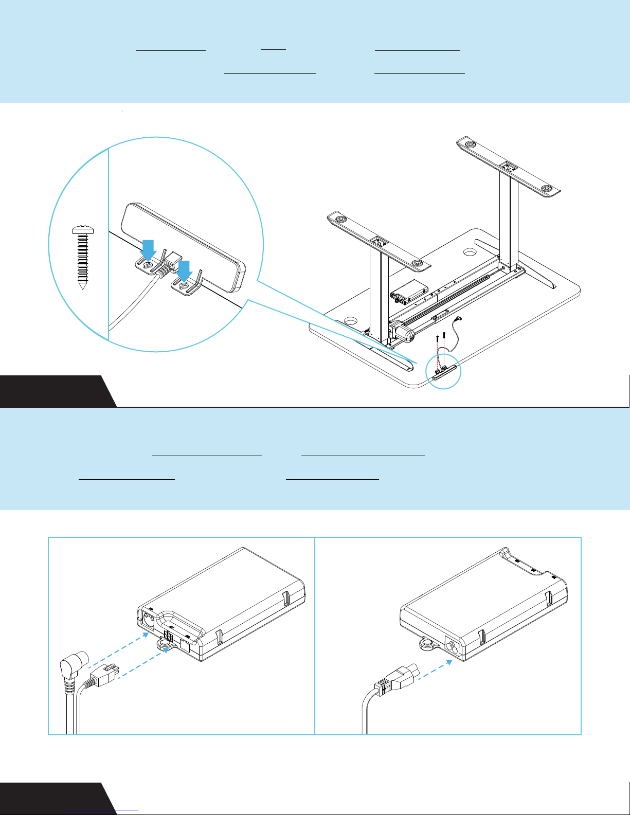
Attach the handset to the top using two ST 3.5x19 screws.
Attach the remaining M5x5 bolts to the drive shaft.
H5
STEP 21
Connect the handset cord and extension cord to the front side of
the control box. Connect the power cord to the back.
STEP 22
FRONT BACK
Page 19
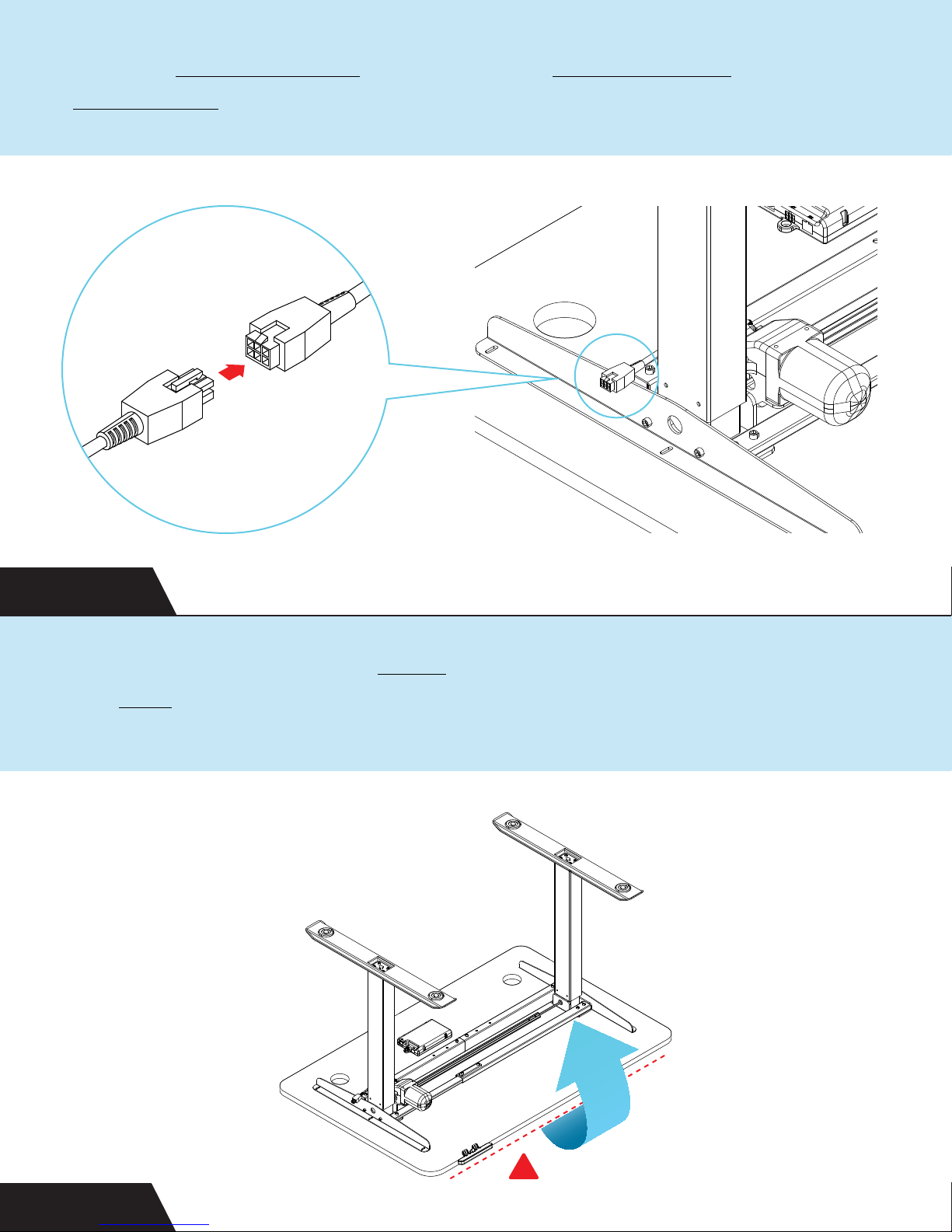
Use the extension cord to connect the leg with motor and
control box.
STEP 23
Be sure to tighten all the bolts. Carefully flip the desk over onto
the feet. Flip the desk over by raising the front side up first, so
you don’t damage the handset.
STEP 24
MIND THE HANDSET
!
Page 20
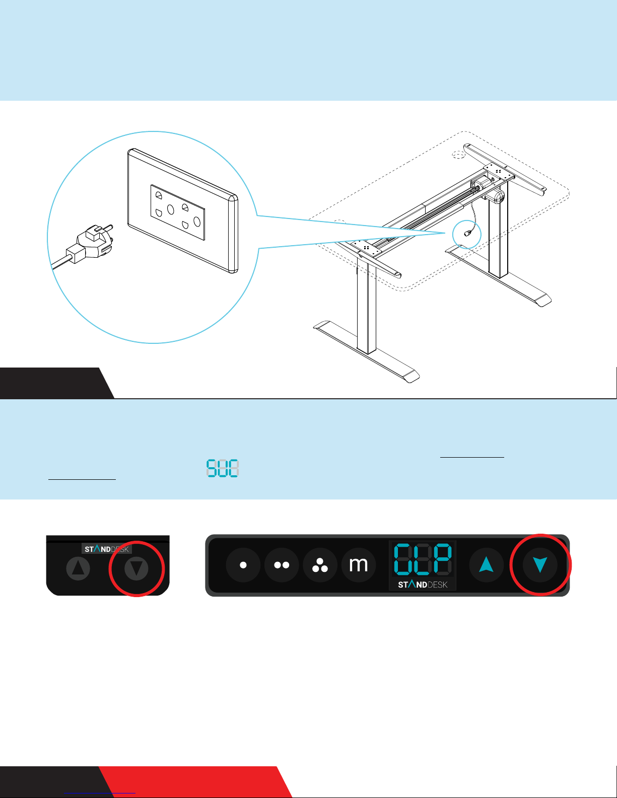
Almost there. Plug in your very own StandDesk!
STEP 25
Finally, it’s time to turn the desk on by holding the down button
until it reaches the lowest position. If you have a memory
handset, it will say for SUCCESS.
We have two kinds of handsets, but the same instructions apply.
A B
DON’T FORGETSTEP 26
Page 21
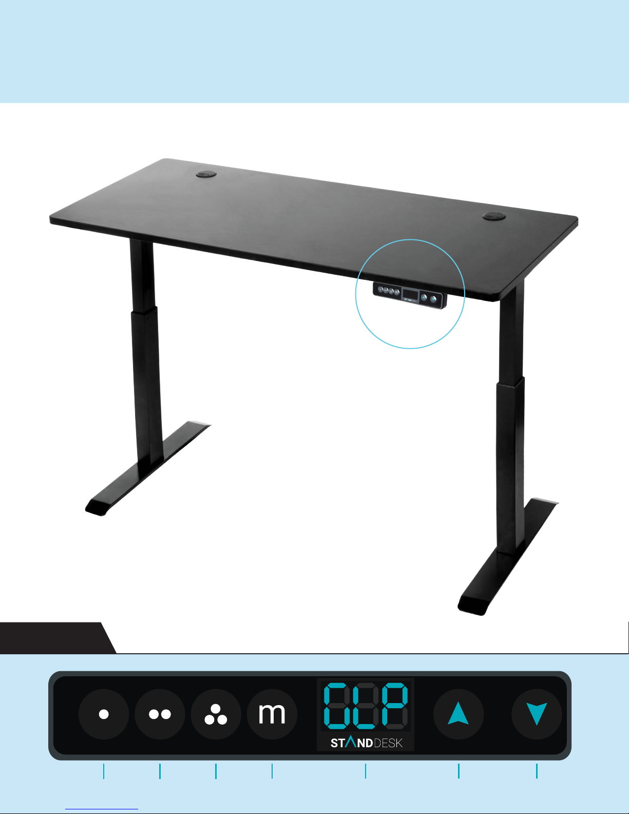
You’re done! Time to celebrate - here’s to standing for your
health, happiness and productivity!
FINISH
Setting 1 Setting 2 Setting 3 Menu LED Display Up Arrow Down Arrow
Page 22
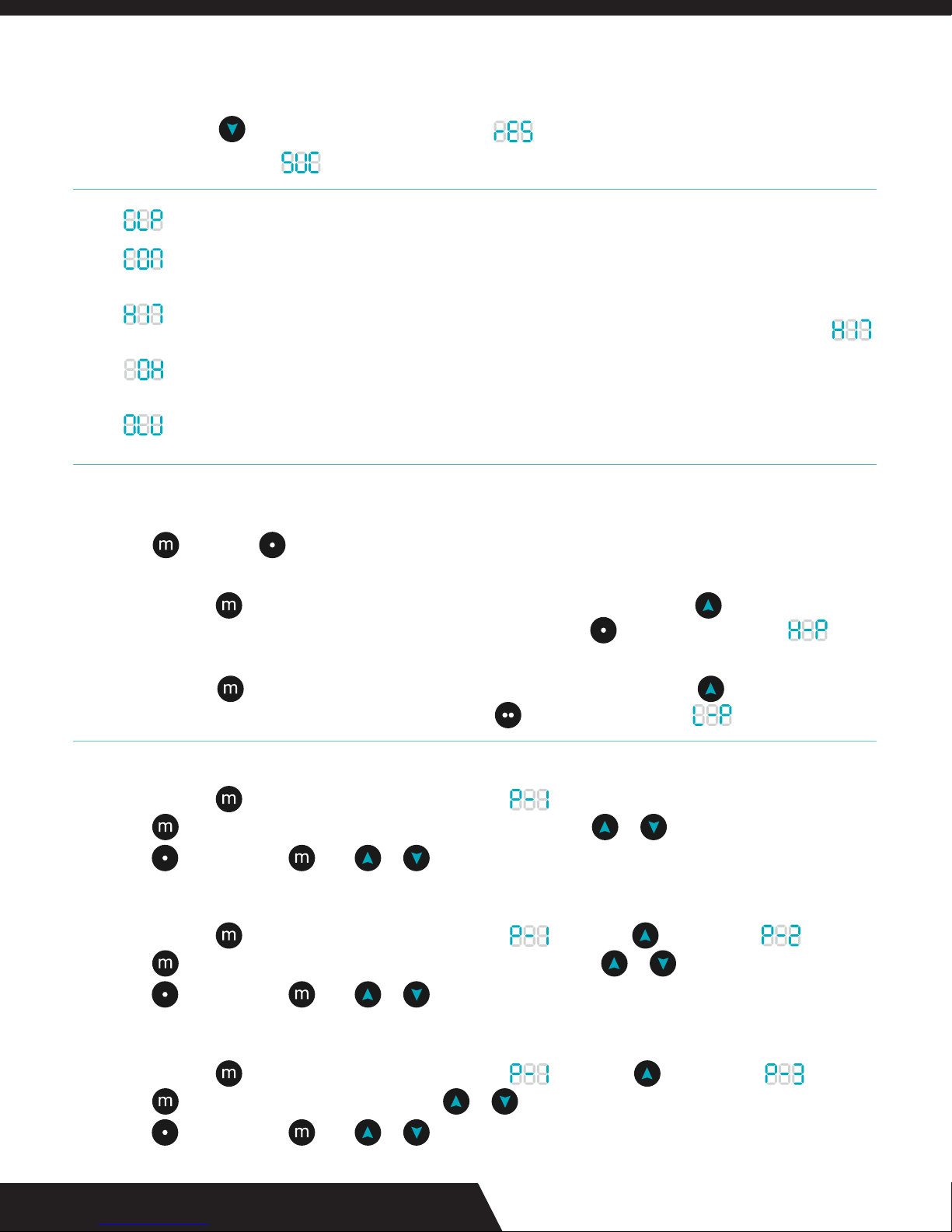
WAKE UP:
Press any button!
CALIBRATE OR RESET:
Press and hold for 15 seconds. Led display shows .
Hold until display shows . Release; the display shows 24”.
GLP:
CON:
HIT:
OH:
OLU:
SET PREFERRED HEIGHTS:
To save your first preferred height; elevate your desk to your desired height with the up/down buttons.
Press then press to save. Repeat steps for remaining two preferred heights.
SET MAXIMUM HEIGHT:
Press and hold for 15 seconds. Release when LED display blinks. Press and hold ; when the desk
reaches your hightest desired height (max is 49”), release. Then press until LED display shows .
SET MINIMUM HEIGHT:
Press and hold for 15 seconds. Release when LED display blinks. Press and hold ; when the desk
reaches your lowest desired height, release. Then press until LED display shows .
Stands for go to lowest position to tell you that your desk must be re-set. See above.
Stands for connection if one of the frame legs is not working properly. Unplug the device and plug it
back in.
Stands for hit. This protects your desk against collisions that could lead to damage. If something hits
your frame while it is raising or lowering, it will automatically stop and memory handset will read .
Stands for overheat if the desk has had two minutes of constant usage. To resolve, wait 15 minutes for
your desk to cool down.
Stands for overload or too much weight on your frame. Either remove some weight or change the load
capacity on your frame in settings (see max/min load capacity).
SET MAX/MIN LOAD CAPACITY:
Press and hold for 20 seconds. LED display will show .
Press then adjust maximum and minimum load capacity by using or .
Press to exit or press then or to choose a different (P) setting.
MEASUREMENT CONVERSION:
Press and hold for 20 seconds. LED display will show , then press once to show .
Press then switch between inches (1) and centimeters (0) by using or .
Press to exit or press then or to choose a different (P) setting.
COLLISION SENSITIVITY:
Press and hold for 20 seconds. LED display will show , then press twice to show .
Press then adjust sensitivity (5-30) by using or . Standard is 15; the lower means more sensitive.
Press to exit or press then or to choose a different (P) setting.
MEMORY HANDSET MANUAL
Page 23
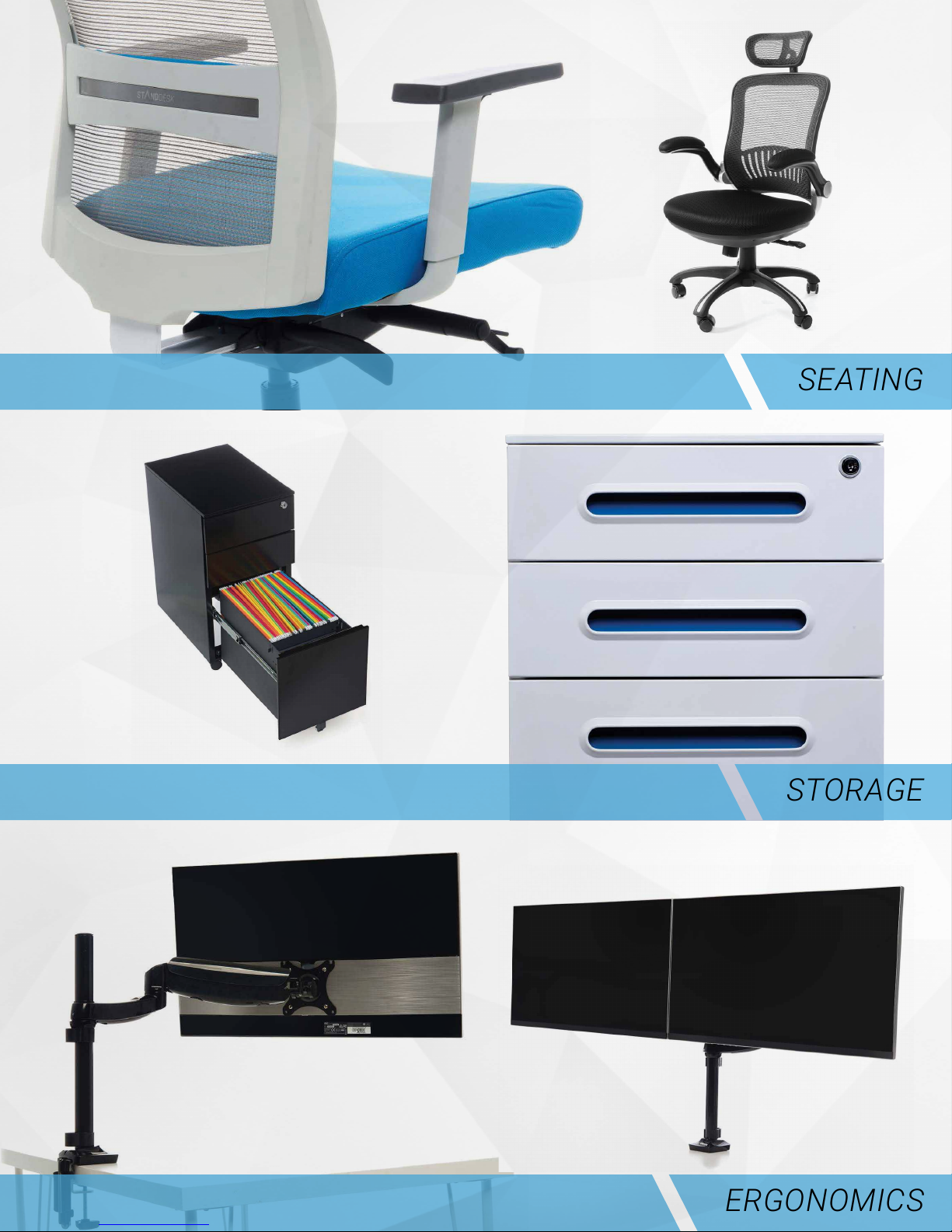
SEATING
STORAGE
ERGONOMICS
Page 24
10% OFF ALL ACCESSORIES
OPTIMIZE10%
PROMO CODE
To learn more about our products,
visit our website at www.standdesk.co
facebook.com/thestanddesk
instagram.com/thestanddesk
twitter.com/thestanddesk
 Loading...