

Standart Horizon GX1850GPS, GX1850GPS/E, GX1800, GX1850, GX1800GPS Owner's Manual
...
Owner’s Manual
EXPLORER NMEA2000 GPS
GX1850GPS GX1850GPS/E
(
European Version
)
EXPLORER NMEA2000
GX1850
EXPLORER GPS
GX1800GPS GX1800GPS/E
(
European Version
)
EXPLORER
GX1800
z International ITU-R M.493-13 Class D DSC (Digital Selective Calling)
(European Version: Meets ITU-R M.493-14)
z NMEA 2000 Compatible (GX1850GPS, GX1850GPS/E and GX1850 only)
z Input and Output of GPS information to NMEA 0183 compatible devices
z Integrated 66 Channel Internal GPS receiver (GX1850GPS, GX1850GPS/E,
GX1800GPS and GX1800GPS/E only)
z Automatic DSC polling of up to 6 ships GPS positions*
z Auto DSC channel selection & DSC test call
z GPS Compass Page*, Enter and Save Waypoints*, Navigate Routes to Locations*
z Automatic Distress Messaging*, MOB Report & Location*, MOB Location Navigation*
z Large Viewable Display, Easy to Mount, Submersible IPX8 (5 feet or 1.5 m for 30 minutes)
z Noise canceling microphone with channel change, 16/S and H/L key buttons
z SSM-70H Remote-Access RAM4 Microphone Second Station & Intercom
z ATIS Mode for European Inland Waterways (GX1850GPS/E and GX1800GPS/E only)
*External GPS device required for GX1850 and GX1800.

TABLE OF CONTENTS
QUICK REFERENCE ........................................... 2
1 GENERAL INFORMATION ............................ 3
2 PACKING LIST ............................................... 3
3 OPTIONAL ACCESSORIES .......................... 3
4 ONLINE WARRANTY REGISTRATION ......... 4
5 Safety Precautions (Be Sure to Read) ........ 4
6 GETTING STARTED ...................................... 6
6.1 ABOUT VHF RADIO .................................................... 6
6.2 SELECTING AN ANTENNA ......................................... 6
6.3 COAXIAL CABLE ......................................................... 6
6.4 DISTRESS AND HAILING (CHANNEL 16) .................. 7
6.5 CALLING ANOTHER VESSEL (CHANNEL 16 OR 9) ... 8
6.6 Accuracy of COG ......................................................... 8
7 CONTROLS AND INDICATORS .................... 9
7.1 FRONT PANEL ............................................................ 9
7.2 MICROPHONE .......................................................... 11
7.3 REAR PANEL ............................................................. 12
8 INSTALLATION ............................................ 13
8.1 SAFETY / WARNING INFORMATION ....................... 13
8.2 LOCATION ................................................................. 13
8.3 MOUNTING THE RADIO ........................................... 13
8.3.1 Supplied Mounting Bracket ................................................ 13
8.3.2 Optional MMB-97 Flush Mount Bracket ............................. 14
8.4 ELECTRICAL CONNECTIONS .................................. 15
8.5
CONNECTION OF EXTERNAL DEVICES TO THE RADIO
8.5.1 Connecting the NMEA 0183/NMEA 0183-HS to the Radio ..... 16
8.5.2 Accessory Cables .............................................................. 17
8.5.3 Connection to External GPS or Chart Plotter ..................... 18
8.5.4 GPS Input - optional SCU-31 External GPS Antenna ........ 18
8.5.5 Connection to External Speaker ........................................ 18
8.5.6 Connecting the SCU-38 External GPS Antenna to
the Radio (GX1850GPS, GX1850GPS/E, GX1800GPS and
GX1800GPS/E only)
8.5.7 Optional SSM-70H (RAM4) Microphone ............................ 19
......................................................... 19
8.6 INITIAL SETUP REQUIRED WHEN TURNING ON
THE POWER FOR THE FIRST TIME ... 21
8.6.1 Maritime Mobile Service Identity (MMSI) ........................... 21
8.7
CONFIRMING GPS SIGNAL (GPS STATUS DISPLAY)
8.8 GPS CONFIGURATION ............................................. 23
8.8.1 Setting the GPS Time ........................................................ 23
8.8.2 Setting the Time Area ......................................................... 24
8.8.3 Setting the Time Format ..................................................... 24
8.8.4 Setting COG to True or Magnetic ....................................... 25
9 BASIC OPERATION ..................................... 26
9.1 TURNING THE TRANSCEIVER ON AND OFF ......... 26
9.2 RECEPTION .............................................................. 26
9.3 TRANSMISSION ........................................................ 26
9.3.1 Transmit Power .................................................................. 27
9.4 BASIC OPERATION OF THE SETUP MENU ............ 27
9.5 TRANSMIT TIME-OUT TIMER (TOT) ........................ 28
9.6 SIMPLEX/DUPLEX CHANNEL USE .......................... 28
9.7 CHANNEL GROUP .................................................... 28
9.8
NOAA WEATHER CHANNELS (in USA and Canada only)
9.8.1 NOAA Weather Alert (USA version only) ........................... 29
9.8.2 NOAA Weather Alert Testing .............................................. 30
9.9 MULTI WATCH (TO PRIORITY CHANNEL) .............. 30
9.9.1 Setup the Multi Watch Operation ....................................... 30
9.9.2 Starting Dual Watch ........................................................... 30
... 16
... 22
... 29
9.10 SCANNING ............................................................. 31
9.10.1 Selecting Scan Type ........................................................ 31
9.10.2 Programming Scan Memory ............................................ 31
9.10.3 Memory Scanning (M-SCAN) .......................................... 32
9.10.4 Priority Scanning (P-SCAN) ............................................. 32
9.11 PRESET CHANNELS: INSTANT ACCESS ............ 33
9.11.1 Programming ................................................................... 33
9.11.2 Operation ......................................................................... 33
9.11.3 Deletion ............................................................................ 34
9.12 MOB OPERATION .................................................. 34
9.13 INTERCOM OPERATION ....................................... 35
9.13.1 Communication ................................................................ 35
9.13.2 Calling .............................................................................. 35
9.14 DEMO MODE ......................................................... 35
10 GPS OPERATION ........................................ 37
10.1 DISPLAYING POSITION INFORMATION .............. 37
10.1.1 GPS Information Numerical Display ................................ 37
10.1.2 GPS Information Compass Display ................................. 37
10.2 CHECKING GPS STATUS ...................................... 37
11 DIGITAL SELECTIVE CALLING (DSC) ....... 38
11.1 GENERAL ............................................................... 38
11.2 DISTRESS ALERT ................................................. 38
11.2.1 Transmitting a Distress Alert ............................................ 38
11.2.2 Receiving a Distress Alert ................................................ 41
11.3 ALL SHIPS CALL .................................................... 42
11.3.1 Transmitting an All Ships Call .......................................... 42
11.3.2 Receiving an All Ships Call .............................................. 43
11.4 INDIVIDUAL CALL .................................................. 44
11.4.1 Setting up the Individual / Position Call Directory ............ 44
11.4.2 Setting up the Individual Call Reply ................................. 45
11.4.3 Enabling the Individual Call Acknowledgment ................. 46
11.4.4 Transmitting an Individual Call ......................................... 46
11.4.5 Receiving an Individual Call ............................................. 48
11.4.6 Setting up the Individual Call Ringer ................................ 49
11.5 GROUP CALL ......................................................... 50
11.5.1 Setting up a Group Call .................................................... 50
11.5.2 Transmitting a Group Call ................................................ 52
11.5.3 Receiving a Group Call .................................................... 54
11.5.4 Setting up the Group Call Ringer ..................................... 54
11.6 POSITION REQUEST ............................................ 55
11.6.1 Setting up a Position Request Reply .............................. 55
11.6.2 Transmitting a Position Request to Another Vessel ......... 56
11.6.3 Receiving a Position Request .......................................... 57
11.6.4 Manual Input of Position Information ............................... 58
11.6.5 Setting up a Position Request Ringer .............................. 58
11.7 POSITION REPORT ............................................... 59
11.7.1 Transmitting a DSC Position Report Call ......................... 59
11.7.2 Receiving a DSC Position Report Call ............................. 60
11.7.3 Navigating to the Reported Position ................................ 60
11.7.4 Saving the Reported Position as a Waypoint ................... 61
11.7.5 Setting up a Position Report Ringer ................................. 62
11.8 AUTO POSITION POLLING ................................... 62
11.8.1 Setting up the Polling Operation ...................................... 62
11.8.2 Setting up the Polling Time Interval ................................. 62
11.8.3 Selecting Vessels to be Automatically Polled ................... 63
11.8.4 Enabling/Disabling Auto POS Polling ............................... 63
11.9 DSC TEST .............................................................. 64
11.9.1 Programming MMSI into Individual Directory ................... 64
11.9.2 Transmitting a DSC Test to Another Vessel ..................... 64
11.9.3 Receiving a DSC Test Call ............................................... 65

TABLE OF CONTENTS
11.10 DSC LOG OPERATION .......................................... 65
11.10.1 Reviewing and Resending a Transmitted Logged Call ... 66
11.10.2 Reviewing a Logged DSC RX Distress Alert and
acknowledgement ... 66
11.10.3 Reviewing Other Logged Calls ...................................... 66
11.10.4 Deleting Logged Calls from the DSC Log Directory ....... 67
11.11 DSC LOOP BACK OPERATION ............................. 67
12 NAVIGATION ................................................ 68
12.1 WAYPOINT OPERATION ....................................... 68
12.1.1 Starting and Stopping Navigation .................................... 68
12.1.2 Setting Up Waypoint Directory ......................................... 69
12.1.3 Selecting the Display Range ............................................ 71
12.1.4 Selecting the Arrival Range .............................................. 71
12.2 ROUTING OPERATION ......................................... 72
12.2.1 Setting Up Routing Directory ........................................... 72
12.2.2 Starting and Stopping Route Navigation .......................... 74
12.2.3 Changing the Destination ................................................. 74
12.2.4 Selecting Automatic or Manual Routing ........................... 74
13 GM OPERATION .......................................... 75
13.1 SETTING UP GM OPERATION .............................. 75
13.1.1 Setting Up GM Group Directory ....................................... 75
13.1.2 Setting Up the Polling Time Interval ................................. 76
13.1.3 Enabling/Disabling Transmission during GM Operation .... 76
13.2 STARTING GM OPERATION ................................. 77
13.2.1 Changing the GM Group Being Monitored ....................... 77
13.2.2 Transmitting a DSC Call to a Group Member .................. 77
13.2.3 Starting Navigation to a Group Member .......................... 78
14 NMEA 2000 SETUP (GX1850 series only) ... 79
14.1 SELECT DEVICE ................................................... 79
14.2 DEVICE NUMBER .................................................. 79
14.3 SYSTEM NUMBER ................................................ 80
14.4 SUMMARY OF THE NMEA 2000 SETUP .............. 80
14.5 COMPATIBLE NMEA 2000 PGN LIST .................... 80
15 CONFIGURATION SETUP ........................... 81
15.1 DISPLAY MODE ..................................................... 81
15.2 DIMMER ADJUSTMENT ........................................ 81
15.3 DISPLAY CONTRAST ............................................ 81
15.4 KEY BEEP .............................................................. 82
15.5 SOFT KEYS ............................................................ 82
15.5.1 Key Assignment ............................................................... 82
15.5.2 Key Timer ......................................................................... 83
15.6 RESET .................................................................... 84
15.6.1 Reset the USER MMSI and ATIS CODE ......................... 84
15.7 SUMMARY OF THE CONFIGURATION SETUP .... 86
16 CHANNEL FUNCTION SETUP .................... 87
16.1 CHANNEL GROUP ................................................. 87
16.2 WEATHER ALERT (USA version only) ................... 87
16.3 SCAN MEMORY ..................................................... 87
16.4 SCAN TYPE ........................................................... 87
16.5 SCAN RESUME ..................................................... 87
16.6 MULTI WATCH ....................................................... 87
16.7 PRIORITY CHANNEL ............................................. 88
16.8 SUB CHANNEL ...................................................... 88
16.9 CHANNEL NAME ................................................... 88
16.10 RX LED DIMMER ADJUSTMENT .......................... 89
16.11 SUMMARY OF THE CANNEL FUNCTION SETUP 89
17 DSC SETUP ................................................. 90
17.1 INDIVIDUAL DIRECTORY ...................................... 90
17.2 INDIVIDUAL REPLY ............................................... 90
17.3 INDIVIDUAL ACKNOWLEDGMENT ....................... 90
17.4 INDIVIDUAL RINGER ............................................. 90
17.5 GROUP DIRECTORY ............................................. 90
17.6 POSITION REPLY .................................................. 91
17.7 AUTO POSITION POLLING ................................... 91
17.8 AUTO POSITION INTERVAL .................................. 91
17.9 AUTO CHANNEL CHANGE ................................... 91
17.10 NO ACTION TIMER ................................................ 92
17.11 WAIT TIME FOR POSITION FIX ............................ 92
17.12 DSC BEEP .............................................................. 92
17.13 SUMMARY OF THE DSC SETUP MENU .............. 92
18 GPS SETUP ................................................. 94
18.1 ORDER OF PRIORITY (GX1850 series only) ........ 94
18.2 COMPASS DIRECTION ......................................... 94
18.3 LOCATION FORMAT .............................................. 94
18.4 TIME OFFSET ........................................................ 95
18.5 TIME AREA ............................................................. 95
18.6 TIME FORMAT ....................................................... 95
18.7 UNITS OF MEASURE ............................................ 95
18.8 MAGNETIC VARIATION ......................................... 95
18.9 NMEA 0183 IN/OUT ............................................... 95
18.9.1 Data Speed ...................................................................... 95
18.9.2 Output Sentences ............................................................ 96
18.10 Position Data Output ............................................... 97
18.11 INTERNAL GPS UNIT ............................................ 97
18.11.1 Unit Power ..................................................................... 97
18.11.2 Pinning ........................................................................... 98
18.11.3 Differential GPS ............................................................ 98
18.12 SUMMARY OF THE GPS SETUP .......................... 99
19 ATIS SETUP
(GX1850GPS/E and GX1800GPS/E only) ... 100
19.1 ATIS CODE PROGRAMMING .............................. 100
19.2 ATIS CH GROUP .................................................. 101
20
SSM-70H (RAM4) REMOTE MIC OPERATION
20.1 REMOTE MIC CONTROLS .................................. 102
20.2 RAM4 SOFT KEY ASSIGNMENT ......................... 105
20.2.1 Key Assignment ............................................................. 106
... 102
21 MAINTENANCE ......................................... 107
21.1 REPLACEMENT PARTS ...................................... 107
21.2 FACTORY SERVICE ............................................ 107
21.3 TROUBLESHOOTING CHART ............................ 108
22 CHANNEL ASSIGNMENTS ....................... 109
22.1 GX1850GPS, GX1850, GX1800GPS and GX1800 ... 109
22.2 GX1850GPS/E and GX1800GPS/E ......................... 112
23 SPECIFICATIONS ...................................... 114
23.1 DIMENSIONS ....................................................... 116
24 FCC RADIO LICENSE INFORMATION ..... 11 7
24.1 STATION LICENSE ................................................ 11 7
24.2 RADIO CALL SIGN ................................................ 11 7
24.3 CANADIAN SHIP STATION LICENSING ............... 117
24.4 FCC / IC INFORMATION ........................................ 117
25 FCC NOTICE .............................................. 118
STANDARD HORIZON Limited Warranty ...... 120
TEMPLATE ...................................................... 121
QUICK REFERENCE
Press and hold the key to turn the radio ON or OFF.
Rotate the VOL knob to adjust the speaker audio volume.
Rotate the SQL knob clockwise to squelch or counterclockwise to
un-squelch the radio.
Press the ▲/▼ keys (or press the microphone ▲/▼ keys) to select the
operating channel.
Press the H/L key to toggle the transmit power between High (25W) and
Low (1W).
Press the 16/S key on the radio or the microphone to select channel 16.
Press and hold the 16/S key on the radio or the microphone to select sub
channel. Press the 16/S key again to revert to the previously selected
channel.
To transmit: place the microphone about 2 cm away from your mouth and
speak in a normal voice level while pressing the PTT switch.
2

1 GENERAL INFORMATION
The STANDARD HORIZON GX1850/GX1800 Marine VHF/FM Marine transceiver is designed to be used in International, USA, Canadian and other Region
Marine channels. The GX1850/GX1800 series can be operated from 11 to 16
VDC and has a switchable RF output power of 1 watt or 25 watts.
The GX1850/GX1800 series is capable of DSC (Digital Selective Calling)
ITU-R M.493 Class D operation with a 66-channel internal GPS (GX1850GPS,
GX1850GPS/E, GX1800GPS and GX1800GPS/E only). Class D operation
allows continuous reception of Digital Selective Calling functions on channel 70
even while receiving calls on the voice channels. The GX1850/GX1800 series
operates on all currently-allocated marine channels and is switchable for use
with International, USA, or Canadian regulations. Emergency channel 16 can
be immediately selected from any other channel by pressing the [16/S] key.
Other features of the GX1850/GX1800 series include: NMEA 2000 compatibility
(GX1850GPS, GX1850GPS/E and GX1850 only) and high expandability. It is
capable of being connected to the optional wired SSM-70H (RAM4) microphone, which provides full remote control of all VHF and DSC functions. It also
includes an intercom feature providing communication between the radio and
the RAM4 microphone, scanning functions, priority scanning, dual watch, DSC
position polling up to 6 vessels, high and low voltage warning, and repeatability
of received GPS location information.
2 PACKING LIST
Open the package and verify it contains the following items:
Transceiver
DC Power Cord
Mounting Bracket and Hardware
Owner’s Manual
DSC Warning Sticker
(GX1850GPS, GX1850, GX1800GPS and GX1800 Only)
3 OPTIONAL ACCESSORIES
Dust Cover (white) ....................................................................... HC1600
Flush-Mount Bracket ................................................................... MMB-97
Remote-Access Microphone (RAM4 Microphone)*1 .................... SSM-70H
*1(The SSM-70H rmware must be Ver. 2.00.00 or later.)
External GPS Antenna with 16 ft (5 m) of Cable (for GX1850GPS,
GX1850GPS/E, GX1800GPS and GX1800GPS/E only)
External GPS Antenna with 49 ft (15 m) of Cable*2 ..................... SCU-31
*2(Built-in GPS Receiver. Refer to section 8.5.4 for connections.)
23 ft (7 m) Extension Cable for SSM-70H (RAM4 Microphone)
External Loud Speaker ................................................................ MLS-300
....... SCU-38
... CT-100
3
4 ONLINE WARRANTY REGISTRATION
Please visit www.standardhorizon.com - Owner’s Corner to register the
GX1850/GX1800 Marine VHF Transceiver.
NOTE: Visiting the STANDARD HORIZON website from time to time may be
benecial. When new products are released, information will appear on the
website.
5 Safety Precautions (Be Sure to Read)
Be sure to read these important precautions, and use this product safely.
Yaesu is not liable for any failures or problems caused by the use or misuse of this
product by the purchaser or any third party. Also, Yaesu is not liable for damages
caused through the use of this product by the purchaser or any third party, except in
cases where ordered to pay damages under the laws.
Types and meanings of the marks
DANGER
WARNING
CAUTION
Types and meanings of symbols
These symbols signify prohibited actions, which must not be done to use this product
safely. For example: indicates that the product should not be disassembled.
These symbols signify required actions, which must be done to use this product safely.
For example:
This mark indicates an imminently hazardous situation, which, if not
avoided, could result in death or serious injury.
This mark indicates a potentially hazardous situation, which, if not
avoided, could result in death or serious injury.
This mark indicates a potentially hazardous situation, which, if not
avoided, may result in minor or moderate injury or only property damage.
indicates the power plug should be disconnected.
Do not operate the device when flammable gas
is generated.
Doing so may result in fire and explosion.
Do not transmit with this device while carrying
or using a medical appliance such as a cardiac
pacemaker. When transmitting, use an external
antenna and keep as far as possible away from
the external antenna.
The radio wave emitted by the transmitter can
cause the medical device to malfunction and result
in injury or death.
4
DANGER
If thunder and lightning develop nearby when
an external antenna is used, immediately turn
this transceiver OFF, and disconnect the exter
nal antenna from it.
A fire, electrical shock, or damage may result.
Do not touch any liquid leaking from the liquid
display with your bare hands.
There is a risk of chemical burns occurring when
the liquid comes into contact with the skin or gets
into the eyes. In this case, seek medical treatment
immediately.
-
WARNING
Do not power this transceiver with a voltage
other than the specified power supply voltage.
A fire, electric shock, or damage may result.
Do not make very long transmissions.
The main body of the transceiver may overheat,
resulting component failure or operator burns.
Do not disassemble or make any alteration to
this product.
An injury, electric shock, or failure may result.
Never touch the antenna during transmission.
This may result in injury, electric shock and
equipment failure.
Do not handle the power plug and connector
etc. with wet hands. Also do not plug and un
plug the power plug with wet hands.
This may result in injury, liquid leak, electric
shock and equipment failure.
Disconnect the power cord and connection
cables before incorporating items sold sepa
rately or replacing the fuse.
This may result in fire, electric shock and equipment failure.
When smoke or strange odors are emitted
from the radio, turn off the power and discon
nect the power cord from the socket.
This may result in fire, liquid leak, overheating,
damage, ignition and equipment failure. Please
contact our company customer support or the retail store where you purchased the device.
Keep the power plug pins and the surrounding areas clean at all time.
This may result in fire, liquid leak, overheating,
breakage, ignition etc.
Never cut the fuse holder off of the DC power
cord.
This may cause a short circuit and result in ignition and fire.
Use only the specified type fuses.
Use of an incorrect fuse may result in fire and
equipment failure.
When connecting a DC power cord, be certain
the positive and negative polarities are correct.
Reverse connection will result in equipment damage.
Do not use DC power cords other than the
one enclosed or specified.
This may result in fire, electric shock and equipment malfunctions.
Do not bend, twist, pull, heat and modify the
power cord and connection cables in an un
reasonable manner.
-
-
-
This may cut or damage the cables and result in
fire, electric shock and equipment failure.
Do not pull the cable when plugging and unplugging the power cord and connection cables.
Always hold the plug or connector when unplugging; if not, a fire, electric shock and equipment
failure may result.
Do not use the device when the power cord
and connection cables are damaged, or when
the DC power connector cannot be plugged
in tightly.
Contact Yaesu Amateur Customer Support or
the retail store where this transceiver was purchased for assistance, as this may result in fire,
electric shock and equipment failure.
Follow the instructions provided when installing
items sold separately and replacing the fuse.
This may result in fire, electric shock and equipment failure.
Use only the provided or specified screws.
Using screws of a different size, may result in
fire, electric shock and component damage.
-
CAUTION
Do not place the transceiver on an unsteady
or sloping surface, or in a location with extreme vibration.
The transceiver may fall or drop, resulting in fire,
injury and equipment damage.
Stay as far away from the antenna as possible
during transmission.
Long-term exposure to electromagnetic radiation
may have a negative effect on the human body.
Do not wipe the case using thinner and benzene etc.
Use only a soft, dry cloth to wipe stains from the
case.
Keep this product out of the reach of children.
Injury to the child, or damage to the transceiver
may result.
Do not put heavy objects on top of the power
cord and connection cables.
This may damage the power cord and connection
cables, resulting in fire and electric shock.
Do not use any products other than the specified options and accessories.
Failure or miss operation may result.
For safety reasons, switch off the power and
pull out the DC power cord connected to the
DC power connector when the device is not
going to be used for a long period of time.
If not, this may result in fire and overheating.
Do not throw the transceiver, or subject it to
strong impact forces.
Physical abuse may result in component damage
and equipment failure.
Keep magnetic cards and videotapes away
from the transceiver.
The data recorded on cash cards or videotapes
may be erased.
Do not stand on top of the product, and do not
place heavy objects on top or insert objects
inside it.
If not, this may result in equipment failure.
5

6 GETTING STARTED
6.1 ABOUT VHF RADIO
The radio frequencies used in the VHF marine band lie between 156 and 158
MHz with some shore stations available between 161 and 163 MHz. The marine
VHF band provides communications over distances that are essentially “line of
sight” (VHF signals do not travel well through objects such as buildings, hills or
trees). Actual transmission range depends much more on antenna type, gain and
height than on the power output of the transmitter. On a xed mount 25 W radio
transmission expected distances can be greater than 25 km, for a portable 5 W
radio transmission the expected distance can be greater than 8 km in “line of sight”.
6.2 SELECTING AN ANTENNA
Marine antennas are made to radiate signals equally in all horizontal directions,
but not straight up. The objective of a marine antenna is to enhance the signal
toward the horizon. The degree to which this is accomplished is called the
antenna gain. It is measured in decibels (dB) and is one of the major factors
in choosing an antenna. In terms of effective radiated power (ERP), antennas
are rated on the basis of how much gain they have over a theoretical antenna
with zero gain. A 1 m, 3 dB gain antenna represents twice as much gain over
the imaginary antenna.
Typically, a 1 m 3 dB gain stainless steel whip is used on a sailboat mast. The
longer 2.5 m 6 dB berglass whip is primarily used on power boats that require
the additional gain.
3dB
6dB
9dB
6.3 COAXIAL CABLE
VHF antennas are connected to the transceiver by means of a coaxial cable
– a shielded transmission line. Coaxial cable is specied by its diameter and
construction.
For runs less than 20 feet (6 m), RG-58/U (about 0.25" (6 mm) in diameter),
is a good choice. For runs over 20 feet (6 m) but less than 50 feet (15 m), the
larger RG-8X or RG-213/U should be used. For cable runs over 50 feet (15 m)
RG-8X should be used. For installation of the connector onto the coaxial cable
refer to the gure.
6
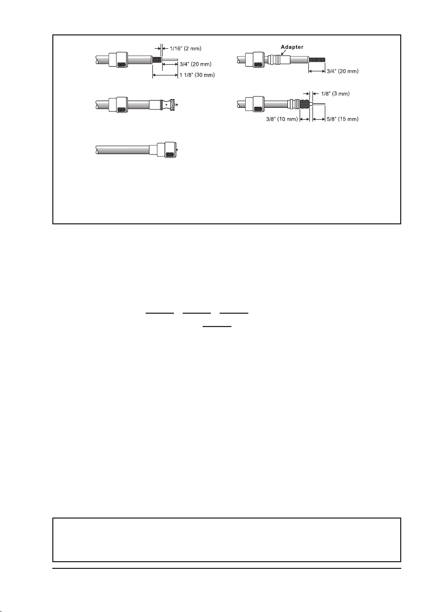
To get the coax cable through a tting and into the boat’s interior, you
may have to cut the end plug off and reattach it later. Follow the directions that come with the connector to attach it. Be sure to make good
soldered connections.
6.4 DISTRESS AND HAILING (CHANNEL 16)
Channel 16 is known as the Hail and Distress Channel. An emergency may be
dened as a threat to life or property. In such instances, be sure the transceiver
is ON and set to CHANNEL 16. Then use the following procedure:
1. Press the microphone push-to-talk switch and say “Mayday, Mayday,
Mayday. This is , , ” (your vessel’s name).
2. Then repeat once: “Mayday, ” (your vessel’s name).
3. Now report your position in latitude/longitude, or by giving a true or magnetic
bearing (state which) to a well-known landmark such as a navigation aid
or geographic feature such as an island or harbor entry.
4. Explain the nature of your distress (sinking, collision, aground, re, heart
attack, life-threatening injury, etc.).
5. State the kind of assistance your desire (pumps, medical aid, etc.).
6. Report the number of persons aboard and condition of any injured.
7. Estimate the present seaworthiness and condition of your vessel.
8. Give your vessel’s description: length, design (power or sail), color and other
distinguishing marks. The total transmission should not exceed 1 minute.
9.
End the message by saying “OVER”. Release the microphone switch and listen.
10. If there is no answer, repeat the above procedure. If there is still no response,
try another channel.
NOTE
The transceiver has the DSC Distress calling, that can transmit a
distress call digitally to all ships with compatible DSC radios. Refer to
section “11 DIGITAL SELECTIVE CALLING (DSC)”.
7

6.5 CALLING ANOTHER VESSEL (CHANNEL 16 OR 9)
Channel 16 may be used for initial contact (hailing) with another vessel.
However, its most important use is for emergency messages. This channel
must be monitored at all times, except when actually using another channel.
It is monitored by the U.S. and Canadian Coast Guards and by other vessels.
Use of channel 16 for hailing must be limited to initial contact only. Calling should not exceed 30 seconds, but may be repeated 3 times at 2-minute
intervals. In areas of heavy radio trafc, congestion on channel 16 resulting
from its use as a hailing channel can be reduced signicantly in U.S. waters
by using channel 9 as the initial contact (hailing) channel for non-emergency
communications. Here, also, calling time should not exceed 30 seconds but
may be repeated 3 times at 2-minute intervals.
Prior to contacting with another vessel, refer to the channel charts in this manual,
and select an appropriate channel for communications after initial contact. For
example, Channels 68 and 69 of the U.S. VHF Charts are some of the channels available to non-commercial (recreational) boaters. Monitor the desired
channel in advance to make sure you will not be interrupting other trafc, and
then go back to either channel 16 or 9 to make initial contact.
When the hailing channel (16 or 9) is clear, press the PTT switch on the mic and
state the name of the other vessel you wish to call and then “this is” followed by
the name of your vessel and your Station License (Call Sign) then release the
PTT switch on the mic. When the other vessel returns your call, immediately
request another channel by pressing the PTT switch on the mic and saying “go
to,” the number of the other channel, say “over” and release the PTT switch on
the mic. Then switch to the new channel. When the new channel is not busy,
call the other vessel.
After a transmission, say “over,” and release the microphone’s push-to-talk
(PTT) switch. When all communication with the other vessel is completed, end
the last transmission by stating your Call Sign and the word “out.” Note that
it is not necessary to state your Call Sign with each transmission, only at the
beginning and end of the contact.
Remember to return to Channel 16 when not using another channel. Some
radios automatically monitor Channel 16 even when set to other channels or
when scanning.
6.6 Accuracy of COG
The error in the COG (the path of the antenna position over ground) due to the
actual ship’s speed over ground shall not exceed the following values:
Speed range (knots) Accuracy of COG output to user
0 to ≤1 knot Unreliable or not available
>1 to ≤17 knots ±3°
>17 knots ±1°
8
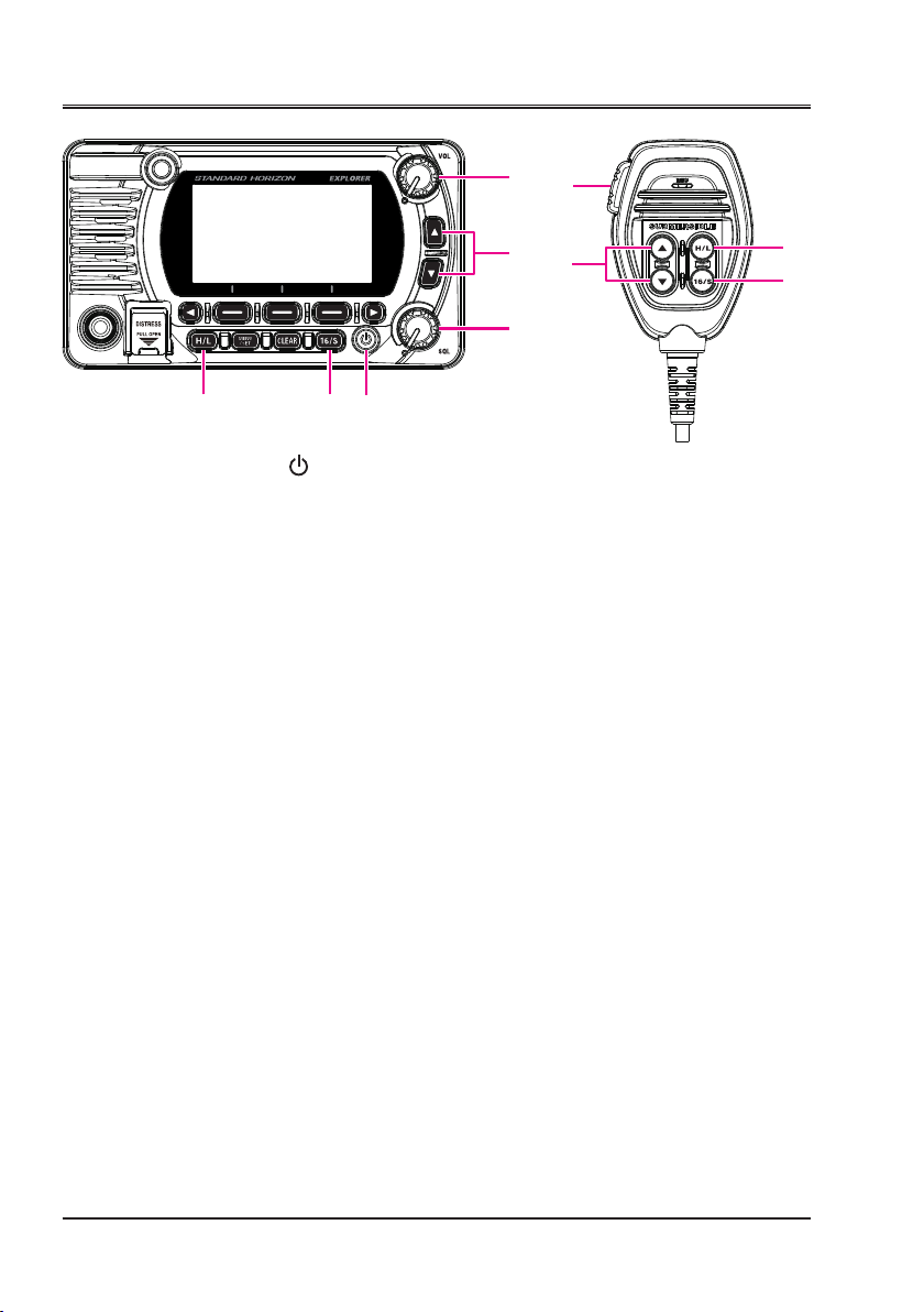
7 CONTROLS AND INDICATORS
⑤
⑥⑦⑧
⑨
This section denes each control of the transceiver. See illustration below for
location of controls. For detailed operating instructions refer to chapter 9 of
this manual.
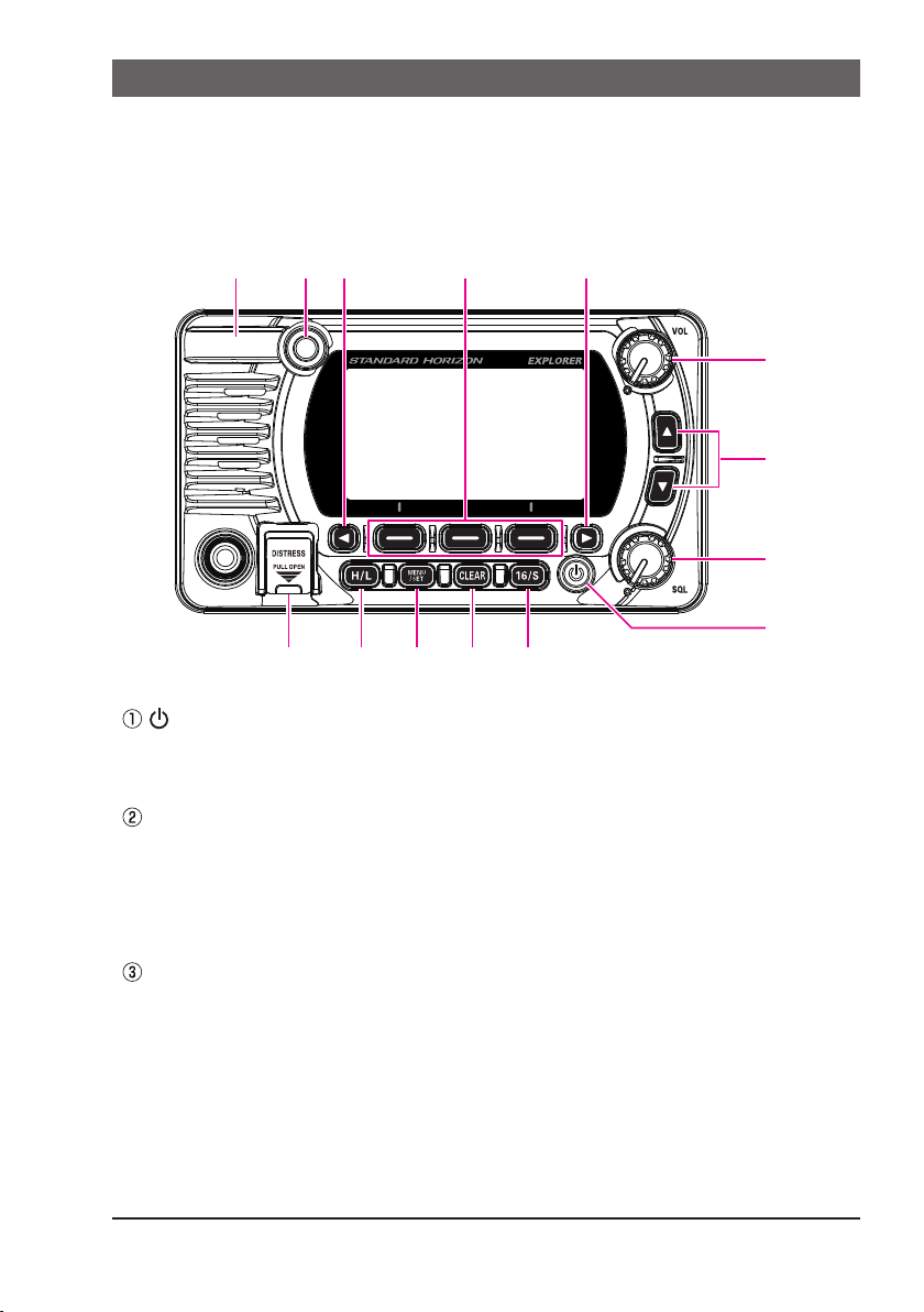
7.1 FRONT PANEL
④
③
②
①
⑩
(Power) key
Press and hold to toggle the radio ON or OFF. When the power is turned
ON, the transceiver is set to the last selected channel.
⑪ ⑫ ⑬ ⑭
SQL knob (Squelch control)
Adjusting this control clockwise, sets the point at which random noise on
the channel does not activate the audio circuits but a received signal will
be heard. This point is called the squelch threshold. Further adjustment of
the squelch control will degrade reception of wanted transmissions.
▲&▼ key
These keys are used to change the operating channel. The Up/Down keys
on the microphone can also be used to change the operating channel.
Press the key momentarily to increase or decrease the channel one step.
Holding the key increases or decreases the channels continuously.
Secondary uSe
While the MENU screen is displayed, press the key to slide the on-screen
menu upward/downward.
9

VOL knob (Volume control)
Adjusts the audio volume level.
Clockwise rotation of this knob increases the internal and speaker microphone volume.
◄ & ► key
/
When the soft keys are displayed, press these keys to switch the function of soft keys.
Secondary uSe
While the MENU screen is displayed, press the key to slide the on-screen
menu to the right/left side.
Soft keys
Press these keys to display the soft keys.
The 3 programmable soft keys can be customized by the Setup Menu
described in section “15.5 SOFT KEYS”.
BUSY Indicator LED
This indicator glows green when the squelch opens.
GPS Antenna (GX1850GPS, GX1850GPS/E, GX1800GPS and
GX1800GPS/E only)
Built in GPS antenna is located here.
DISTRESS key
Used to send a DSC Distress Call. To send the distress call, refer to section
“11.2.1 Transmitting a Distress Alert”.
H/L key
Press this key to toggle between 25 W (High) and 1 W (Low) power. When
the TX output power is set to “Low” while the transceiver is on channel 13 or
67 (USA Channel group only), the output power will temporarily switch from
“Low” to “High” power until the PTT switch of the microphone is released.
This key is not available on transmit inhibited and low power only channels.
MENU/SET key
Press to access MENU.
Press and hold to access SETUP MENU. For details, refer to section
“9.4 BASIC OPERATION OF THE SETUP MENU”.
CLEAR key
Press this key to cancel a menu selection.
16/S key
Pressing this key immediately recalls channel 16 from any channel location.
Holding down this key selects the SUB channel (The default SUB channel
setting is channel 9). Pressing this key again reverts to the previous selected
working channel.
10

7.2 MICROPHONE
①
③
④
②
⑤
PTT (Push-To-Talk) switch
When in radio mode and the PTT switch is pressed, the transmitter is
enabled for voice communications to another vessel.
When an optional SSM-70H Microphone RAM4 is connected and intercom
mode is selected, pressing the PTT switch enables voice communications
from the transceiver to the SSM-70H second station microphone RAM4.
▲ & ▼ key
These keys on the microphone are used to select channels and to choose
menu items.
Microphone
The internal microphone transmits your voice and reduces background
noise using Clear Voice Noise Reduction Technology.
When transmitting, position the microphone about 2 cm away from your
mouth. Speak slowly and clearly into the microphone.
H/L key
Press this key to toggle between 25 W (High) and 1 W (Low) power. When
the TX output power is set to “Low” and the transceiver is on channel 13 or
67 (USA Channel group only), the output power will temporarily switch from
“Low” to “High” power until the PTT switch of the microphone is released. High
power TX is not available on transmit inhibited and low power only channels.
16/S key
Pressing this key immediately selects channel 16 from any channel location.
Holding down this key selects the Sub channel (The default SUB channel
setting is channel 9). Pressing this key again reverts to the previous selected
working channel.
11
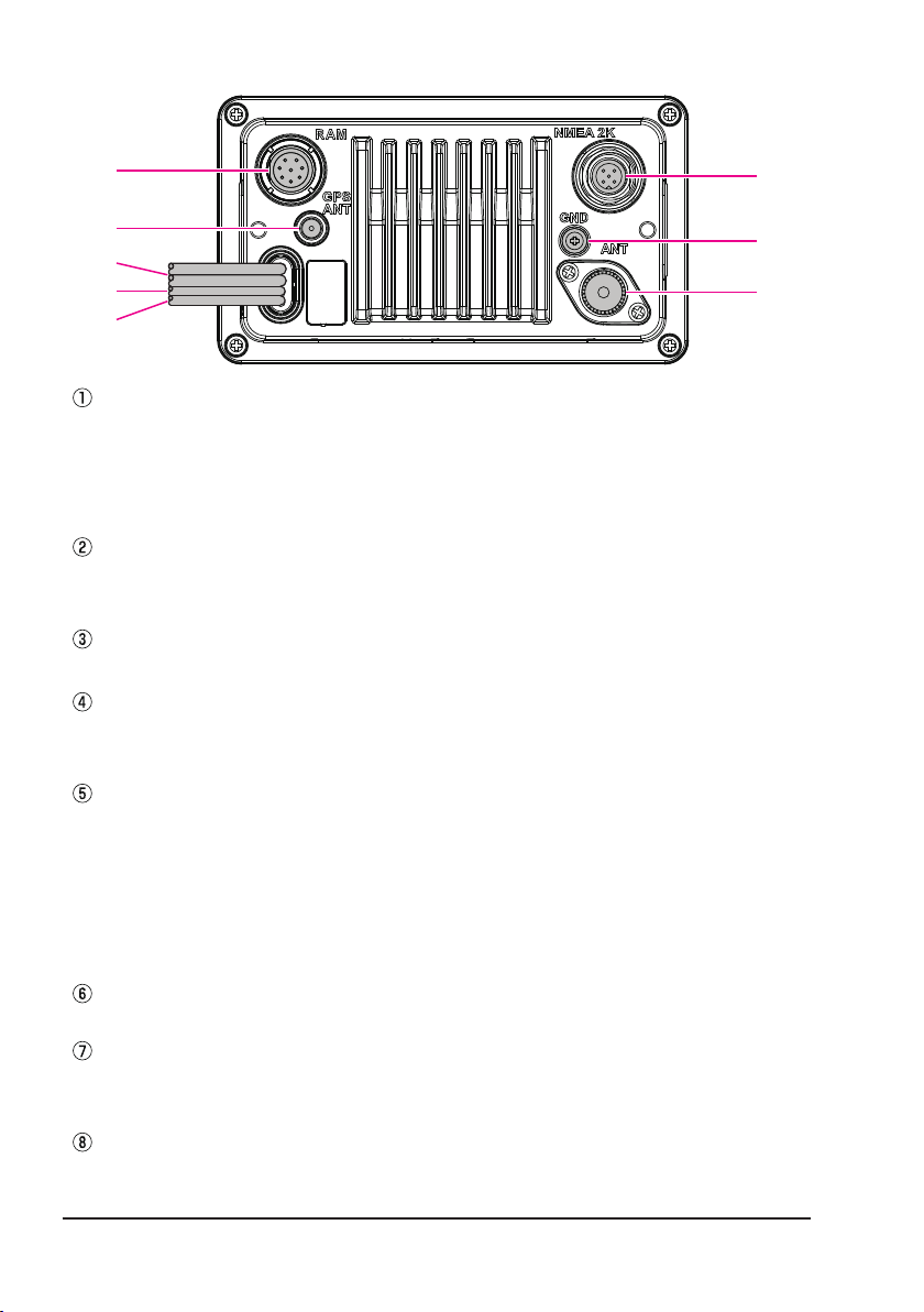
7.3 REAR PANEL
①
②
⑥
⑦
③
④
⑧
⑤
RAM Remote Access Microphone Connector
Connects the SSM-70H (RAM4) Remote Station Microphone. Refer to
section “20 SSM-70H (RAM4) REMOTE MIC OPERATION” for details.
NOTE: It is not allowed to connect the SCU-30 Wireless Access Point to
this connector.
GPS ANT Connector (GX1850GPS, GX1850GPS/E, GX1800GPS and
GX1800GPS/E only)
Connects the optional SCU-38 External GPS Antenna.
DC Input Cable
Connects the transceiver to a DC power supply capable of delivering 11 to 16 VDC.
Accessory Connection Cable (Yellow, Green, Gray and Brown)
Connects the transceiver to a GPS chart plotter. Refer to section “8.5.2
Accessory Cables”.
EXTERNAL Speaker Connection Cable (White & Shield)
Connects the transceiver to an optional external speaker. Refer to section
“3 OPTIONAL ACCESSORIES” for the available optional STANDARD
HORIZON accessories.
Speaker connections:
White: External Speaker (+)
Shield: External Speaker (−)
NMEA 2K Connector (GX1850GPS, GX1850GPS/E and GX1850 only)
Connects to the NMEA 2000 network.
GND Terminal (Ground Terminal)
Connects the transceiver to ships ground, for safe and optimum performance.
Use the screw supplied with the transceiver only.
VHF ANT Jack (VHF antenna jack)
Connects an antenna to the transceiver. Use a marine VHF antenna with
an impedance of 50 ohms.
12

8 INSTALLATION
8.1 SAFETY / WARNING INFORMATION
Operation of this radio is restricted to occupational use, work related operations
only where the radio operator must have the knowledge to control the exposure
conditions of passengers and bystanders by maintaining the minimum separation distance of 3 feet (1 m). Failure to observe these restrictions will result in
exceeding the FCC RF exposure limits.
Antenna Installation:
The antenna must be located at least 3 feet (1 m) away from passengers in
order to comply with the FCC RF exposure requirements.
8.2 LOCATION
The radio can be mounted at any angle. Choose a mounting location that:
• complies with the compass safe distances shown in the table below to
prevent interference to a magnetic compass
Transceiver Unit 1.0 m
Handset 0.5 m
• provides accessibility to the front panel controls
• allows connection to a power source and antennas
• has nearby space for installation of a microphone hanger
• is at least 3 feet (1 m) away from the radio’s antenna
• the signals from the GPS satellites can be adequately received
NOTE: To insure the radio does not affect the compass or radio’s performance
is not affected by the antenna location, temporarily connect the radio in the
desired location and:
a. Examine the compass to see if the radio causes any deviation
b. Connect the antenna and key the radio. Check to ensure the radio is
operating correctly by requesting a radio check.
8.3 MOUNTING THE RADIO
8.3.1 Supplied Mounting Bracket
The supplied mounting bracket allows desktop mounting.
Use a 13/64" (5.2 mm) bit to drill the holes to a surface which is more 0.4 inch
(10 mm) thick and can support more than 3.3 lbs (1.5 kg) and secure the bracket
with the supplied screws, spring washers, at washers, and nuts.
13
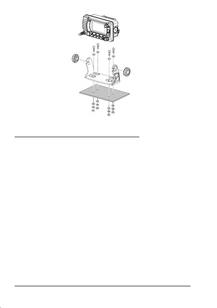
Desktop Mounting
8.3.2 Optional MMB-97 Flush Mount Bracket
A GPS receiver and antenna are located in the front panel of the GX1850GPS,
GX1850GPS/E, GX1800GPS and GX1800GPS/E. In many cases the radio
may be ush mounted, however before cutting holes to ush mount the radio
it is recommended to temporarily connect the radio to power and turn it ON
in the location where it will be ush mounted to conrm on the display that it
is able to receive a GPS location. If the radio is not able to receive a location,
a connection to a GPS Chart plotter with NMEA 0183 output, or the optional
SCU-38 External GPS Antenna may be needed to receive GPS satellite signals.
1. Use the template (page 121) to mark the location where the rectangular
hole is to be cut. Conrm the space behind the dash or panel is deep enough
to accommodate the transceiver (at least
There should be at least 1/2 inch (1.3 cm) between the transceiver’s heat-
sink and any wiring, cables or structures.
2. Cut out the rectangular hole and insert the transceiver.
3. Fasten the brackets to the rear panel of the transceiver (see illustration).
4. Turn the adjusting screw to adjust the tension so that the transceiver is tight
against the mounting surface.
3.74
inches (95 mm) deep).
14
Adjusting Screw
GPS Navigation Receiver
Optional SCUExternal GPS Antenna
6.42″ (163 mm)
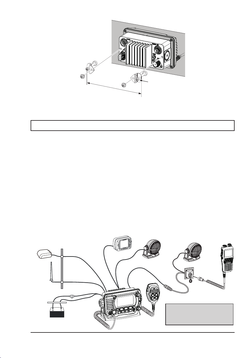
8.4 ELECTRICAL CONNECTIONS
CAUTION
Reverse polarity battery connections will damage the radio!
Connect the power cord and antenna to the radio. Antenna and Power Supply
connections are as follows:
1. Mount the antenna at least 3.28 feet (1 m) away from the radio. At the rear
of the radio, connect the antenna cable. The antenna cable must have
a PL259 connector attached. RG-8/U coaxial cable must be used if the
antenna is 25 feet (7.6 m) or more from the radio. RG58 cable can be used
for distances less than 25 feet (7.6 m).
2. Connect the red power wire to a 13.8 VDC ±20% power source. Connect
the black power wire to a negative ground.
3.
If an optional external speaker is to be used, refer to section 8.5 for connections.
4. It is advisable to have a Certied Marine Technician check the power output
and the standing wave ratio of the antenna after installation.
Optional MLS-300
38
External Speaker
Optional MLS-300
External Speaker
Optional SSM-70H
(RAM4) Remote MIC
Antenna
Red
Power Source
Water proof
Deck Outlet
Fuse
Black
Accessory Cables
Ensure that the SCU-38, the
MLS-300 and the SSM-70H are
located at a distance that does not
affect the magnetic compass.
15
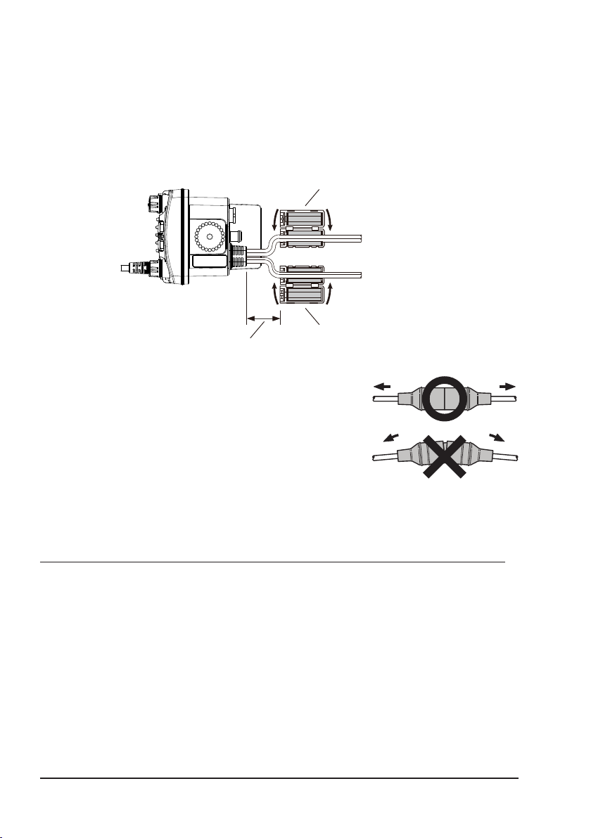
Ferrite Cores
To suppress RF interference that can cause abnormal operation of the transceiver, attach the supplied two ferrite cores as shown below: one to the accessory
cable and the DC Power code together, and other to the NMEA Cable and the
Speaker Cable together. Then snap the two halves of each ferrite core together.
Attach each ferrite core as close as possible to the transceiver body.
Finally, wind some plastic tape around each ferrite core, to prevent vibration
from causing the two halves to split apart.
Ferrite Core
Snap together
{
DC Power Code
{
Accessory Cable /
Speaker Cable
Snap together
Ferrite Core
As close as possible
Fuse Replacement
To remove the fuse from the fuse holder, hold both
ends of the fuse holder and pull the fuse holder apart
without bending the fuse holder. When replacing the
fuse, conrm that the fuse is tightly xed into the metal
contact located inside the fuse holder. If the metal
contact holding the fuse is loose, the fuse holder may
heat up.
8.5 CONNECTION OF EXTERNAL DEVICES TO THE RADIO
8.5.1 Connecting the NMEA 0183/NMEA 0183-HS to the Radio
External GPS Device Connections (NMEA 0183 4800 baud or NMEA 0183-HS
38400 baud)
The GX1850/GX1800 series can select the NMEA baud rate between “4800
bps” and “38400 bps”. Refer to section “18.9 NMEA 0183 IN/OUT” for selection.
NMEA Input (GPS Information)
• The transceiver can read NMEA 0183 version 2.0 or higher, and NMEA
0183-HS version 1.01 or higher.
• The NMEA 0183 input sentences are GLL, GGA, RMC, GNS, GSA, and
GSV (RMC sentence is recommended).
16

• If 4800 baud (default) is selected:
The Yellow and Green input wires are at 4800 baud.
• If 38400 baud is selected:
The Yellow and Green input wires are at 38400 baud.
NMEA Output (DSC and GPS information)
• The NMEA 0183 output sentences are DSC and DSE.
• If 4800 baud (default) is selected:
The Gray and Brown wires output DSC and DSE sentences.
• If 38400 baud is selected:
The Yellow and Brown output wires are at 38400 baud and include
DSC (DSC, DSE) sentences.
• GSA, GSV, GLL, GGA, and RMC sentences can be output from the trans-
ceiver using settings in the GPS setup menu (refer to section “18.9 NMEA
0183 IN/OUT”).
For further information on interfacing and setting up GPS operation, contact
the manufacturer of the externally connected GPS receiver.
If you have further questions, please contact your Dealer.
8.5.2 Accessory Cables
The image and table below show the wires of the transceiver and the connections to optional devices such as an external GPS antenna and a GPS chart
plotter.
CAUTION
Care must be taken not to touch any of the NMEA wires to positive 12
VDC or the radio may be damaged.
When connecting the Chart Plotter, External GPS receiver, or External Speaker
strip off about 1" (2.5 cm) of the specied wire’s insulation, then splice the ends
together.
The transceiver uses NMEA 0183/-HS protocol to share coordinates and DSC
information to and from a GPS chart plotter.
Wire Color/Description Connection Examples
Yellow: NMEA GPS Input (+) NMEA (+) output of GPS
Green: NMEA GPS Input (−)*
White: NMEA DSC Output (+) NMEA (+) input of GPS
Brown: NMEA DSC Output (−)*
NOTE: *1Some GPS chart plotters have a single wire for NMEA signal ground. In this
case, connect the NMEA input (−) to the GPS chart plotter’s single NMEA signal ground
wire, and leave the NMEA output (−) open. In case the assignment of power supply and
ground of a GPS chart plotter to be used is different from that of the radio, connect the
signal ground wire of the GPS chart plotter to the ground terminal (GND) on the rear
panel of the radio.
1
NMEA (−) output or common ground of GPS
1
NMEA (−) input or common ground of GPS
17
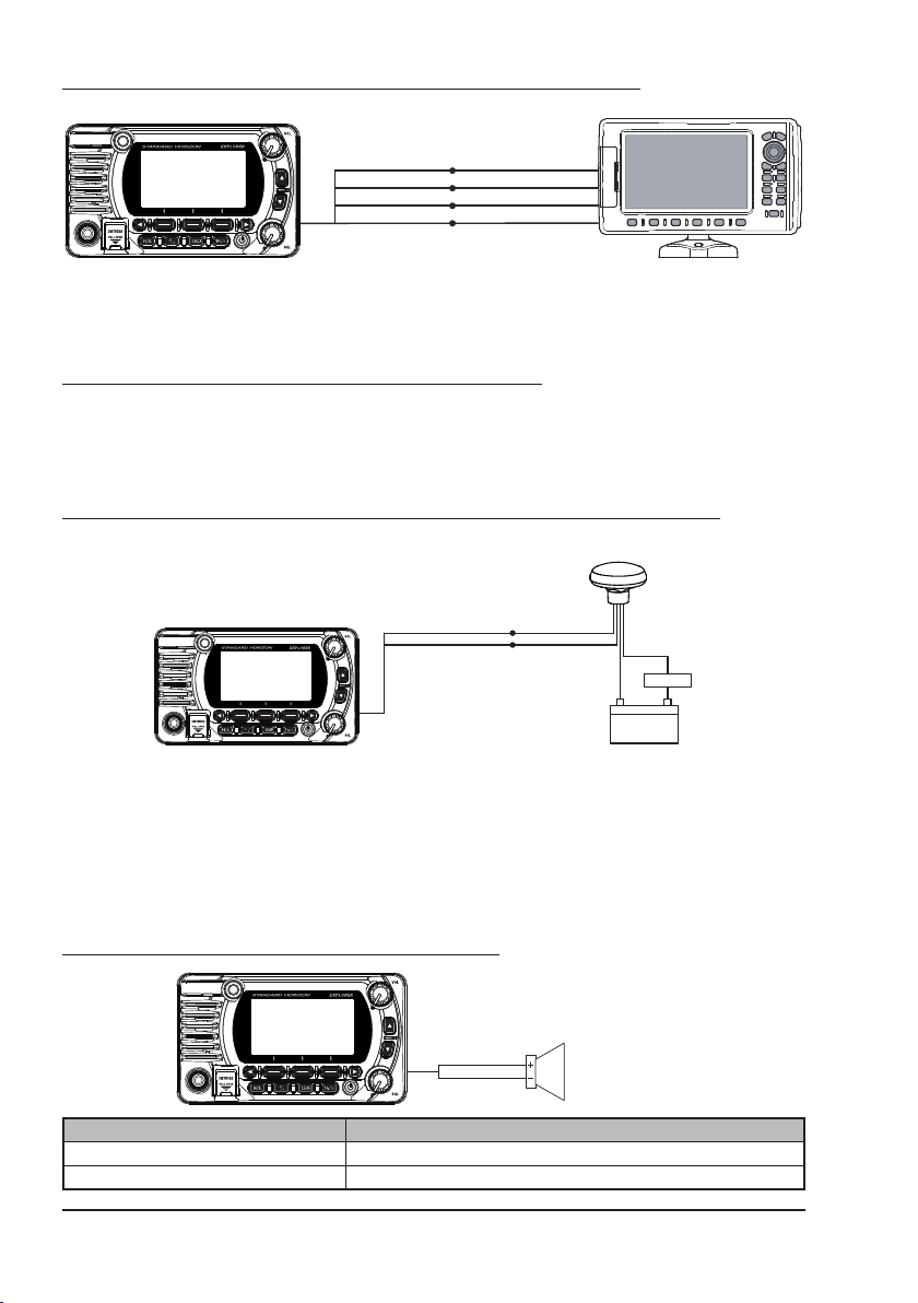
8.5.3 Connection to External GPS or Chart Plotter
GPS Chart Plotter
Plotter ConnectionRadio Wires
2
Yellow: NMEA IN
Green: NMEA IN (−
White: NMEA OUT
Brown: NMEA OUT (−
(+)*
2
)*
(+)
)
NMEA OUT
NMEA OUT (−
(+)
NMEA IN
NMEA IN (−
(+)
)
)
NOTE: *2To input the GPS coordinates from an external GPS device to the transceiver,
the NMEA GPS input (+) (yellow) and the NMEA GPS input (-) (green) wires may be
connected to the NMEA output of the external GPS antenna or GPS chart plotter.
To connect with an external device at 38400 baud
To connect with an external device at 38400 baud, the transceiver may be setup
to receive GPS coordinates and send DSC signals at 38400 baud. Refer to
section “18.9 NMEA 0183 IN/OUT” for details.
8.5.4 GPS Input - optional SCU-31 External GPS Antenna
External GPS Antenna
SCU-31
Radio Wires
Yellow: NMEA IN(+)
Green: NMEA IN(−)
Brown
Black
Black
2A Fuse
(−) (+)
12V Battery
Red
The SCU-31 External GPS Antenna (Built-in GPS receiver) is supplied with
49 feet (15 m) of cable and a connector. To connect the SCU-31 to the transceiver, cut off the 6 pin antenna connector, strip the white insulation to expose
the Red, Black and Brown wires and connect as shown in the diagram. All
other wires are not used and may be cut off. The 2 amp fuse is not included.
8.5.5 Connection to External Speaker
White
Shield
Wire Color/Description Connection Examples
White: External Speaker (+) Positive wire of external 4 Ohm External speaker
Shield: External Speaker (−) Negative wire of external 4 Ohm External speaker
18
External Speaker
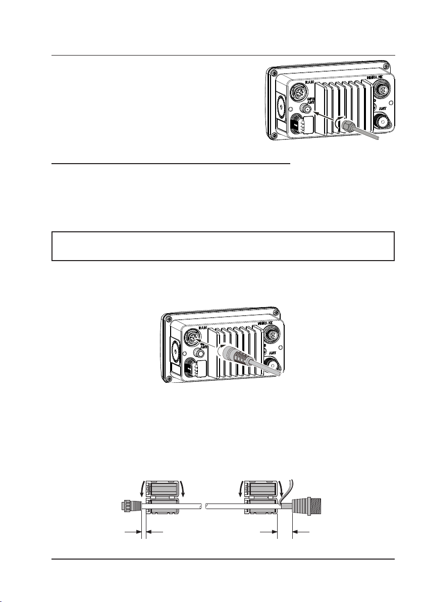
8.5.6 Connecting the SCU-38 External GPS Antenna to the Radio
External Speaker
(GX1850GPS, GX1850GPS/E, GX1800GPS and GX1800GPS/E only)
Connect the SCU-38 cable to the coaxial GPS
ANT connector on the rear panel, then tighten
the cable nut (see illustration at the right).
NOTE: The SCU-38 External GPS Antenna is
always more preferred than the internal GPS
antenna.
8.5.7 Optional SSM-70H (RAM4) Microphone
The transceiver is capable of using an SSM-70H (RAM4) Remote Station
Microphone to control all the Radio functions. In addition, the transceiver can
operate as a full function intercom system between the SSM-70H microphone
and the transceiver.
WARNING
Do not connect or remove the SSM-70H (RAM4) microphone while
the radio is powered ON. This may result in equipment failure.
1. Connect the Routing Cable (supplied with the SSM-70H) to the RAM
connector (eight pins) on the rear panel, then tighten the cable nut (see
the below illustration).
2. Install the two ferrite cores (supplied with the SSM-70H Remote Station
Microphone) to the routing cable or the CT-100 extension cable, then snap
the halves together. These cores should be installed near the connectors
of the transceiver and the microphone ends of the cable.
3. Attach the ferrite cores as close as possible to the plugs, as shown below.
{
Connections
As close as possible
to SSM-70H
(RAM4)
to GX1800
Ferrite Core
As close as possible
Ferrite Core
Routing Cable or
CT-100 Extension Cable
19
NOTE
Caution!: Before cutting the cable, it must be disconnected from the rear
panel of the transceiver.
The routing cable can be cut and spliced, however care needs to be taken
when reconnecting the wires to ensure water integrity.
After cutting you will notice there are the following wires:
Yellow, Green, White, Brown and Red/Shield
4. Finally, wind some plastic tape
around each ferrite core, to
prevent vibration from causing
the two halves to split apart.
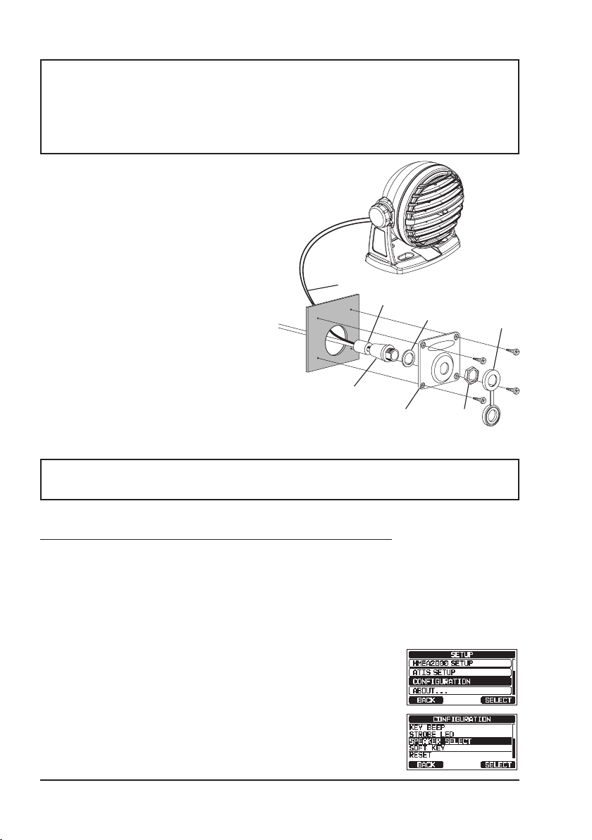
5. Referring to the illustration at the
right, make a 30 mm hole in the
wall, then insert the extension
cable into this hole. Connect the
gasket and mount base to the
extension cable connector using
External Speaker Connections
Ferrite Core
Gasket
the nut.
6. Drill the four screw holes (approx. 2 mm)
into the wall, then install the mounting
base to the wall using four screws.
7. Put the rubber cap onto the nut.
The installation is now complete.
Wall
Routing Cable
Mounting Bracket
WARNING
Cap
Nut
It is not recommended to plug or unplug the SSM-70H (RAM4) Remote
Station Microphone into the routing cable while the radio is powered ON.
Connecting an External Speaker to the RAM4 Mic Cable
In noisy locations and the MLS-300 optional external speaker may be connected
to the white speaker wires on the RAM4 routing cable. The RAM4 can drive
either the internal speaker or the external speaker one at a time. When connecting an external speaker, follow the procedure below to turn the RAM4 audio OFF
and enable the external speaker connected to the RAM4 routing cable wires.
1.
On the RAM4 microphone, press and hold the [MENU] key.
2. Rotate the DIAL/ENT knob to select “CONFIGURA-
TION”, then press the [SELECT] soft key.
3. Rotate the DIAL/ENT knob to select “SPEAKER
SELECT”, then press the [SELECT].
20
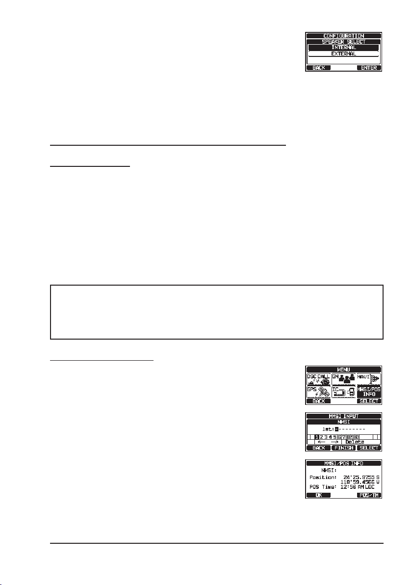
4. Rotate the DIAL/ENT knob to select “INTERNAL” or
“EXTERNAL”, then press the [SELECT] soft key.
5. Press the [CLEAR] key to return to radio operation.
8.6 INITIAL SETUP REQUIRED WHEN TURNING ON THE
POWER FOR THE FIRST TIME
8.6.1 Maritime Mobile Service Identity (MMSI)
What is an MMSI?
An MMSI is a nine-digit number used on marine transceivers capable of using
Digital Selective Calling (DSC) signal transmission. This number is used like
a telephone number to selectively call other vessels.
THIS NUMBER MUST BE PROGRAMMED INTO THE RADIO TO OPERATE
DSC FUNCTIONS.
How can I obtain an MMSI assignment?
Contact the Radio Licensing Authority for your country for information on obtaining an
MMSI number.
WARNING
The MMSI can be input only once, be careful not to input the incorrect MMSI number. If the MMSI number needs to be reset, contact
Standard Horizon to obtain the required reset code. Refer to section
“15.6.1 Reset the USER MMSI and ATIS CODE”.
Programming the MMSI
1. Press the [MENU/SET] key to display “MENU”.
2. Press the [▲] or [▼] key to select “MMSI/POS INFO”,
then press the [SELECT] soft key. (To cancel, press
the [BACK] soft key.)
3. The “MMSI INPUT” screen is displayed if the MMSI
has not yet been input.
When the transceiver entry has been completed, it is
only possible to check the MMSI on this screen.
*********
4. Press the [▲]/[▼]/[◄]/[►] keys to select the rst
number of your MMSI, then press the [SELECT] soft
key to step to the next number.
21
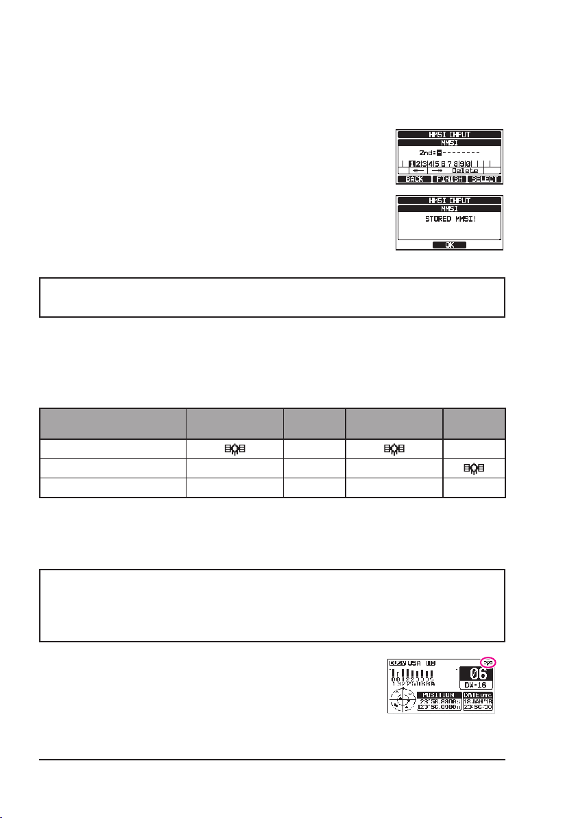
5. Repeat step 4 to set your MMSI number (9 digits).
If a mistake is made entering in the MMSI number,
press the [▲]/[▼]/[◄]/[►] keys to select “←” or “→”,
press the [SELECT] soft key until the incorrect character is selected, then perform step 4.
6. When nished programming the MMSI number, press
the [FINISH] soft key. The radio will ask you to input
the MMSI number again. Perform steps 4 through 6
above.
7. After the second number has been input, press the
[FINISH] soft key to store the MMSI.
*********
8. Press the [OK] soft key to return to radio operation.
NOTE
To check the MMSI after programming to ensure it is correct, perform
steps 1 to 2. The current MMSI number is shown on the display.
8.7 CONFIRMING GPS SIGNAL (GPS STATUS DISPLAY)
When the GX1850/GX1800 series receives the GPS signal from the internal
GPS receiver or the NMEA 2000 or NEMA 0183, an icon will appear on the
display as shown below.
Receive GPS signal from
Internal GPS Receiver
NMEA 0183 I/O I/O I/O
NMEA 2000 2K 2K – –
GX1850GPS
GX1850GPS/E
GX1850
– –
GX1800GPS
GX1800GPS/E
GX1800
If there is a problem with the NMEA connection between the radio and the GPS,
the GPS icon will blink continuously until the connection is corrected.
NOTE
Using the GPS position information from an external source (NMEA
0183 or NMEA 2000) is preferred, rather than relying on the internal
GPS receiver. To check the status of the Internal GPS receiver, do not
input signals from the external device.
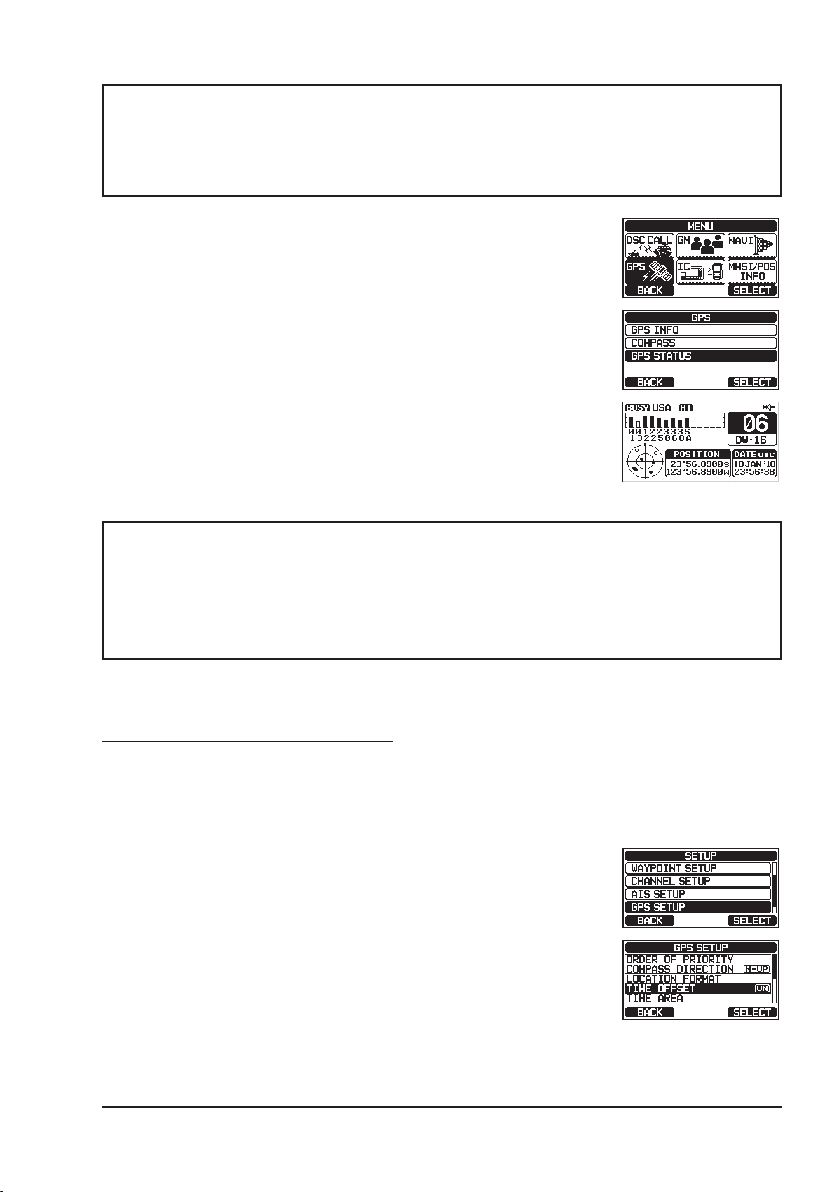
The transceiver has a GPS status display which shows
the satellites currently being received, along with a
graphical (bar-graph) representation of the relative
signal strengths from the satellites.
(GPS Status Display mode)
22
NOTE
When the GPS reception is limited, such as the ush mounting of the
GX1850GPS, GX1850GPS/E, GX1800GPS and GX1800GPS/E, it is
recommended to connect the optional External GPS Antenna SCU-38
to the GPS ANT connector on the rear panel.
1. Press the [MENU/SET]key to display “MENU”.
2. Press the [▲] or [▼] key to select “GPS”, then press
the [SELECT] soft key.
3. Press the [▲] or [▼] key to select “GPS STATUS”,
then press the [ENTER] soft key to display the GPS
status currently being received.
4. Press the [CLEAR] key to return to radio operation.
NOTE
For the transceiver to properly show the GPS status page when an
external GPS receiver or a chart plotter is connected, the external
device must be setup to output GSA and GSV NMEA 0183 sentences.
When using the equipment of NMEA 2000, it must be able to output
PGN No.129540 (GNSS Sats in View).
8.8 GPS CONFIGURATION
8.8.1 Setting the GPS Time
The transceiver shows GPS satellite time or UTC (Universal Time Coordinated)
time in factory default. A time offset is needed to show the local time in your
area. The time offset must be changed in order for the radio to display the
current time in your area.
1. Press and hold the [MENU/SET]key.
2. Press the [▲] or [▼] key to select “GPS SETUP”, then
press the [SELECT] soft key.
3. Press the [▲] or [▼] key to select “TIME OFFSET”,
then press the [SELECT] soft key.
23
4. Press the [▲] or [▼] key to select time offset of your
location. If “00:00” is assigned, the time is the same
as UTC or GPS satellite time.
5. Press the [ENTER] soft key to store the time offset.
6. Press the [CLEAR] key to return to radio operation.
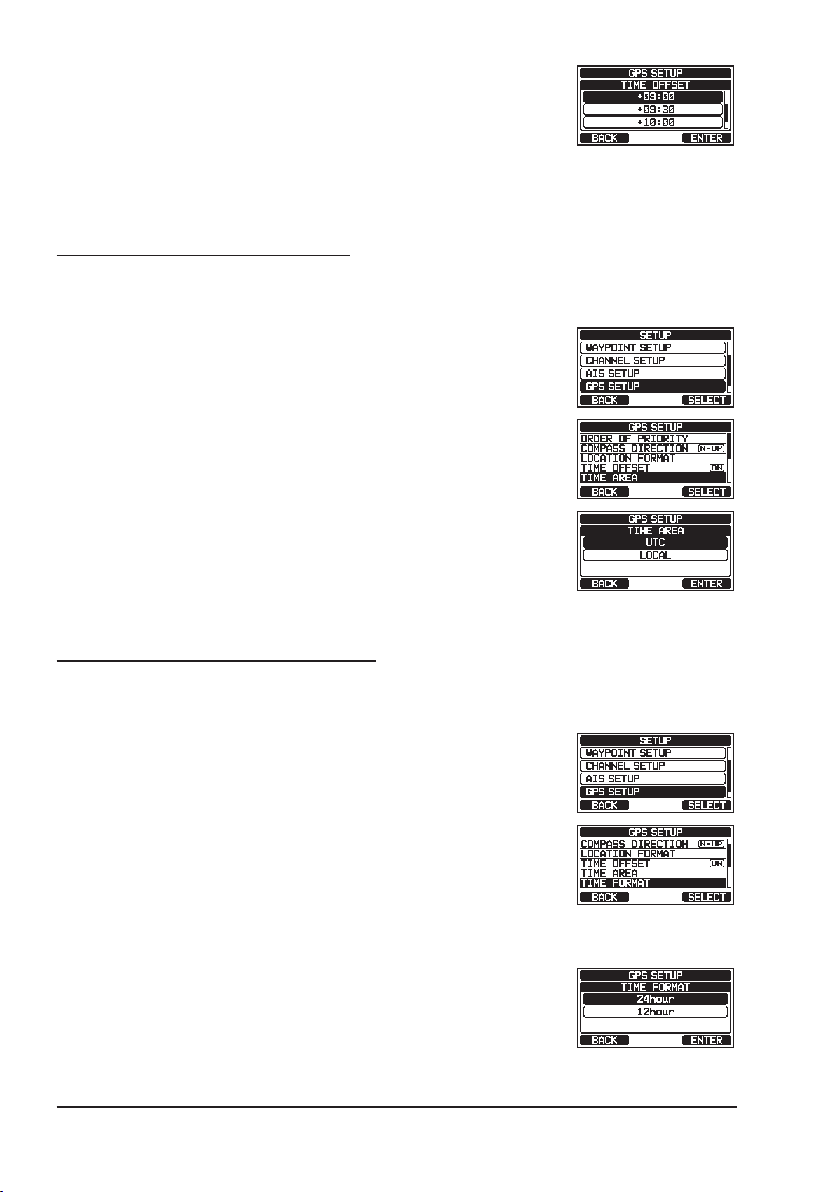
8.8.2 Setting the Time Area
This menu selection allows the transceiver to show UTC time or local time
with the offset.
1. Press and hold the [MENU/SET] key.
2. Press the [▲] or [▼] key to select “GPS SETUP”, then
press the [SELECT] soft key.
3. Press the [▲] or [▼] key to select “TIME AREA”, then
press the [SELECT] soft key.
4. Press the [▲] or [▼] key to select “UTC” or “LOCAL”.
5. Press the [ENTER] soft key to store the selected
setting.
7. Press the [CLEAR] key to return to radio operation.
8.8.3 Setting the Time Format
This menu selection allows the transceiver to be setup to show time in 12-hour
or 24-hour format.
1. Press and hold the [MENU/SET] key.
2. Press the [▲] or [▼] key to select “GPS SETUP”, then
press the [SELECT] soft key.
3. Press the [▲] or [▼] key to select “TIME FORMAT”,
then press the [SELECT] soft key.
4. Press the [▲] or [▼] key to select “24hour” or
“12hour”.
5. Press the [ENTER] soft key to store the selected
setting.
6. Press the [CLEAR] key to return to radio operation.
24
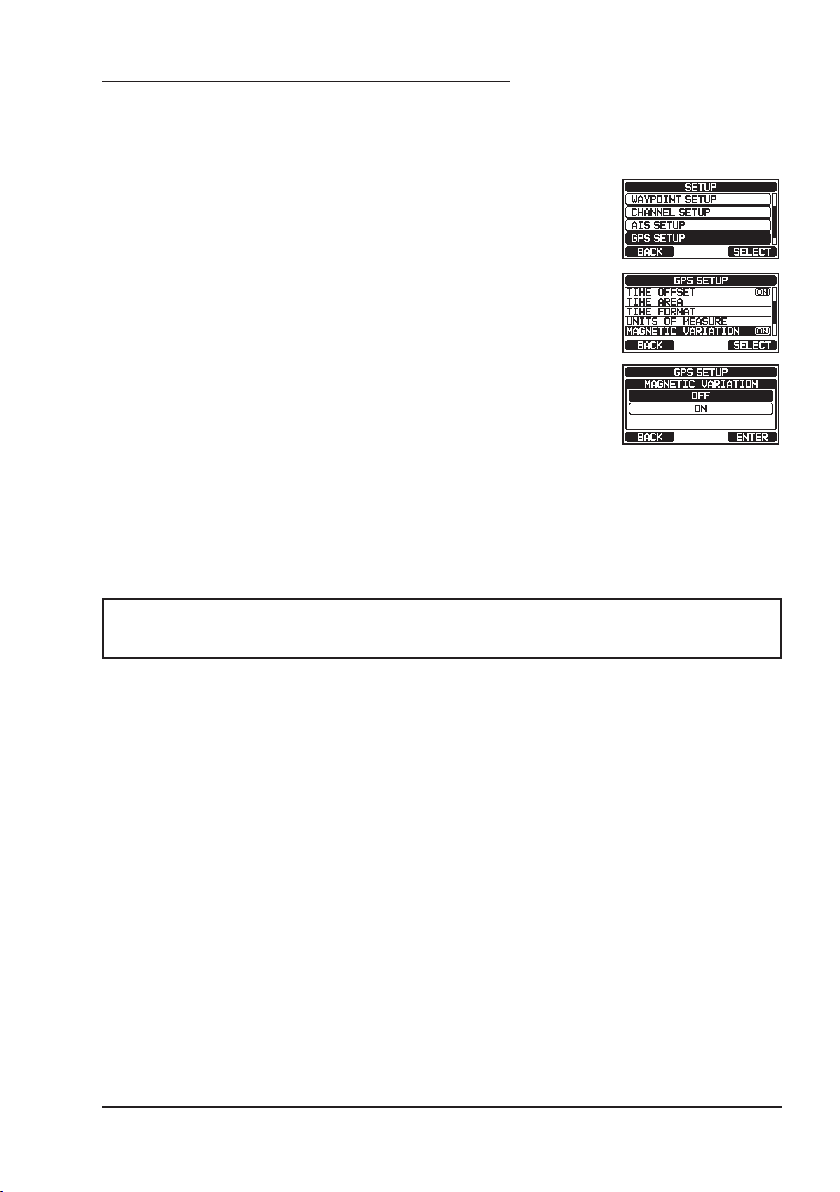
8.8.4 Setting COG to True or Magnetic
The GPS COG (Course Over Ground) and the BRG from a Waypoint Target
magnetic variation may be selected to show in ON or OFF. Factory default is
“OFF” however by following the steps below the COG can be changed to “ON”.
1. Press and hold the [MENU/SET] key.
2. Press the [▲] or [▼] key to select “GPS SETUP”, then
press the [SELECT] soft key.
3. Press the [▲] or [▼] key to select “MAGNETIC
VARIATION”, then press the [SELECT] soft key.
4. Press the [▲] or [▼] key to select “OFF” or “ON”.
5. Press the [ENTER] soft key to store the selected
setting.
6. Press the [CLEAR] key to return to radio operation.
NOTE
The “ON” setting is effective only when the RMC sentences with magnetic data are input from external devices such as a GPS Chart Plotter.
25

9 BASIC OPERATION
9.1 TURNING THE TRANSCEIVER ON AND OFF
1. After the transceiver has been installed, ensure that the power supply and
antenna are properly connected.
2. Press and hold the
3. Press and hold the key again to turn the radio OFF.
9.2 RECEPTION
1.
Rotate the SQL knob fully counterclockwise. This state is known as “squelch off”.
2. Turn up the VOL knob until noise or audio from the speaker is at a comfortable level.
3. Rotate the SQL knob, clockwise until the random noise disappears. This
state is known as the “squelch threshold”.
4. Press the [▲] or [▼] key to select the desired channel.
Refer to the channel chart on page 109 for available
channels.
5. When a signal is received, adjust the volume to the
desired listening level. The BUSY Indicator Lamp
glows green, and the “BUSY” indicator on the display
indicates that communications are being received.
9.3 TRANSMISSION
1. Perform steps 1 through 4 of RECEPTION.
2. Before transmitting, monitor the channel to ensure it is clear.
THIS IS AN FCC REQUIREMENT!
3. Press the microphone’s PTT (push-to-talk) switch.
The “TX” indicator on the LCD is displayed.
4. Speak slowly and clearly into the microphone.
5. When the transmission is nished, release the microphone PTT switch.
key to turn the radio ON.
NOTE
Position your mouth about 2 cm away from the microphone and speak
in a normal voice.
26

9.3.1 Transmit Power
The TX output power of the transceiver is set to high (25 W) in factory default,
and the “HI” indicator is displayed on the top part of the screen.
To switch the TX output power:
1. Press the [H/L] key on the front panel or the microphone to switch between HI (25 W) or LO (1 W) output
power.
NOTE: When the TX output power is set to “Low” while
the transceiver is on channel 13 or 67 (USA Channel
group only), the output power will temporarily switch
from “Low” to “High” power until the PTT switch of the
microphone is released. This soft key is not function
on transmit inhibited and low power only channels.
9.4 BASIC OPERATION OF THE SETUP MENU
Using the setup menu, the various functions of the transceiver can be customized to match the user’s needs and preferences. Items to be adjusted
may be selected from the respective lists and the appropriate settings made
for the various intended operations.
1. Press and hold the [MENU/SET] key on the operation
mode screen.
2. Press the [▲] or [▼] key to select the function item,
then press the [SELECT] soft key.
3. Press the [▲] or [▼] key to select the setting item,
then press the [SELECT] soft key.
4. Press the [▲] or [▼] key to select the desired setting.
5. Press the [ENTER] soft key to store the selected
setting.
6. Press the [CLEAR] key to return to radio operation.
(The display can also be returned to the previous
screen by pressing the [BACK] soft key.)
The above process is used when making the Setup Menu adjustments that
follow in this Operating Manual.
[
Press & hold
]
“DSC SETUP” “INDIVIDUAL DIRECTORY”
27
9.5 TRANSMIT TIME-OUT TIMER (TOT)
When the PTT switch on the microphone is held down, transmit time is limited
to 5 minutes. This limits unintentional transmissions due to a stuck microphone.
About 10 seconds before automatic transmitter shutdown, a warning beep will
be heard from the speaker(s). The transceiver will automatically go to receive
mode, even if the PTT switch is continually held down. Before transmitting
again, the PTT switch must rst be released and then pressed again.
NOTE
Once the transmitter is shut down by the TOT, transmission on the
channel is only allowed 10 seconds after the shutdown.
9.6 SIMPLEX/DUPLEX CHANNEL USE
Refer to the VHF MARINE CHANNEL CHART (Page 109) for instructions on
use of simplex and duplex channels.
NOTE
All channels are factory-programmed in accordance with FCC (USA),
ISED (Canada), and International and region regulations. Mode of
operation cannot be altered from simplex to duplex or vice-versa.
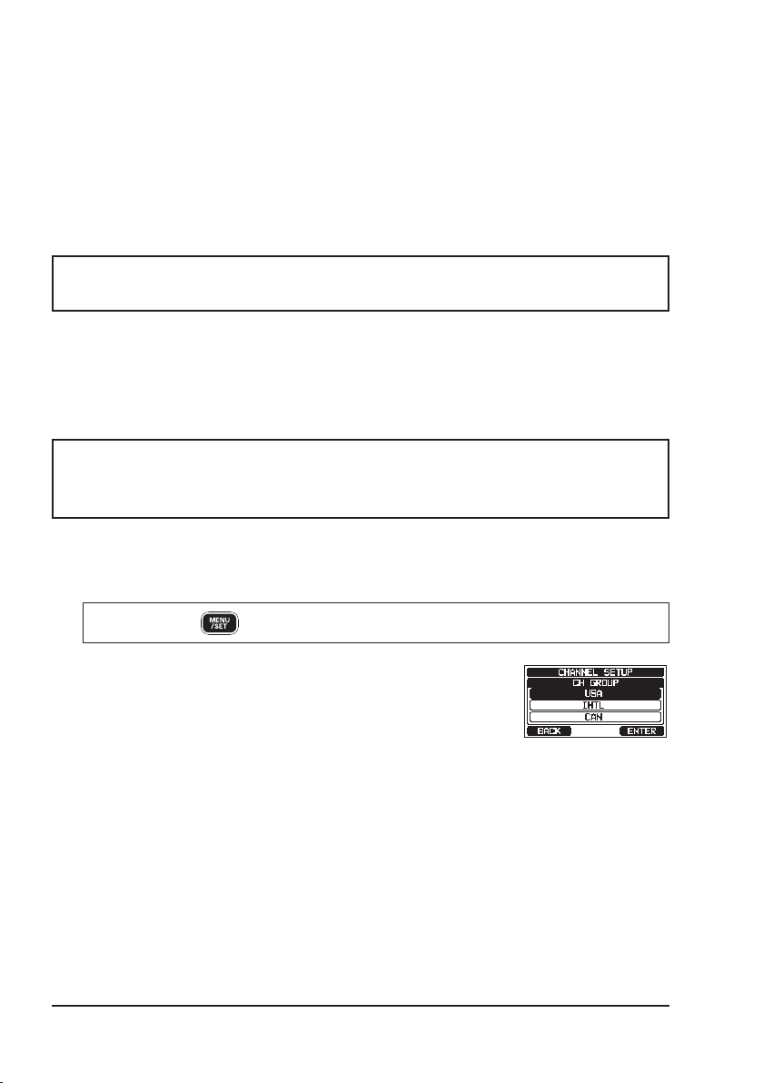
9.7 CHANNEL GROUP
Set the Channel Group according to the region:
[
Press & hold
1.
]
“CHANNEL SETUP” “CHANNEL GROUP”
2. Press the [▲] or [▼] key to select the desired channel
1
group “USA”, “INTL”, or “CAN”
*
.
*1In the European version, when setting the region, the
selected European Channel Group will be displayed
instead of “CAN” group. For details, refer to the “Note
on the Setting the Region” on the separate yellow
insert sheet.
3.
Press the [ENTER] soft key to store the selected setting.
4. Press the [CLEAR] key to return to radio operation.
Refer to the “22 CHANNEL ASSIGNMENTS” (page 109) for allocated channels in each mode.
28
 Loading...