

Standart Horizon FF525 Installation Manual
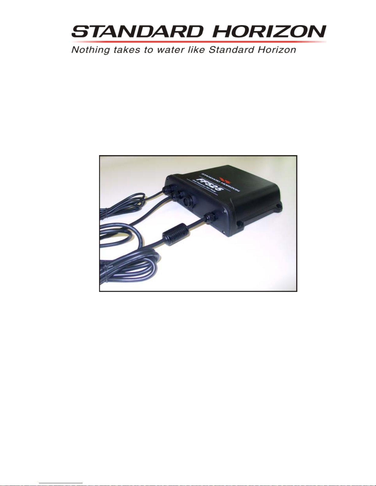
FF525 BLACK BOX FISH FINDER
INST ALLATION MANUAL

Page 4 FF525 Installation Manual
FCC Compliance Statement
This device complies with Part 15 of the FCC limits for Class A digital devices. This
equipment generates, uses and can radiate radio frequency energy and, if not
installed or used in accordance with the instructions may cause harmful interference
with radio communications.
There is no guarantee that interference will not occur in a particular instance. If this
equipment does cause harmful interference to other equipment, try to correct the
problem by relocating the equipment.
Consult an authorized STANDARD HORIZON dealer or other qualified service
technician if the problem cannot be corrected. Operation is subject to the following
conditions: (1) This device cannot cause harmful interference, and (2) this device
must accept any interference received, including interference that may cause
undesired operation.
CAUTION
- The FF525 contains dangerous high-voltage circuits which only experienced
technicians can handle.
- STANDARD HORIZON will not be liable for errors contained herein, or for
incidental or consequential damages in connection with the performance or use of
this material.
- Because we frequently update our software and applications, the pictures shown
through this Owner’s Manual may be slightly different from what you see.
WARNING
- When plugging in or unplugging a transducer to the FF525 make sure power is
turned off.
Copyright 2012. YAESU MUSEN CO., LTD. All rights reserved. Printed in Italy.
No portion of this manual may be reproduced without the permission of YAESU MUSEN CO., LTD.
CODE: Installation Manual - Issue C - 100212e

FF525 Installation Manual Page 5
TABLE OF CONTENTS
1. INTRODUCTION ...................................................................................................................6
1.0 GENERAL INFORMATION...............................................................................6
1.1 PACKING LIST ................................................................................................. 7
1.1.0 Replacement Parts .............................................................................. 7
2. MOUNTING THE FF525 ....................................................................................................... 8
2.0 INSTALLATION.................................................................................................8
2.1 CONNECTIONS................................................................................................8
2.2 POWER CONNECTIONS.................................................................................9
2.3 GPS CHART PLOTTER CONNECTIONS ....................................................... 9
2.3.1 TEE Cable ............................................................................................9
2.4 OPTIONAL CONNECTIONS ..........................................................................11
2.4.0 NMEA Output .....................................................................................11
2.4.1 Alarm Buzzer......................................................................................11
2.4.2 Temperature Sensor ..........................................................................11
3. TRANSDUCER ...........................................................................................................12
3.0 TRANSDUCER MOUNTING .......................................................................... 12
3.0.0 Power Boats .......................................................................................12
3.0.1 Sailboats.............................................................................................12
3.0.2 Transducer Types .............................................................................. 13
3.0.3 Low Profile Thru-Hull..........................................................................13
3.0.4 Transom (power boats only) .............................................................. 13
3.0.5 Fairing Block.......................................................................................13
3.0.6 In-hull..................................................................................................13
3.0.7 Optional Transducer ID Sensors ......................................................13
3.0.8 Fish Finder Basics..............................................................................14
4. FF525 SPECIFICATIONS ..........................................................................................15
5. INSTALLATIONS TIPS .............................................................................................. 16
INDEX ...................................................................................................................................... 17

Page 6 FF525 Installation Manual
1. INTRODUCTION
This manual provides installation of the FF525 and associated 600W or 1kW transducers.
For operations, refer to the FF525 Operation Manual for
CP180/CP180i, CP190i, CP300/CP300i,
CPV350, CP500, CPV550, CP590
and the FF525 Operation Manual for CPN700i, CPN1010i.
1.0 GENERAL INFORMATION
The FF525 advanced features include:
· 16/256 colors display user selectable
· A-Scope (displays Sonar Echo in real time)
· Preset modes (Fish, Cruise)
· 2x and 4x Zoom (capability to magnify any part of the Fish Finder image of a fixed rate)
· Bottom Lock (capability to magnify a user defined range around the bottom)
· White Line (help distinguish between fish and bottom, when fish are swimming close
to the bottom)
· Sensitivity Time Control (STC) reduces Surface Clutter shown on the display by
reducing echoes from water disturbances
· Surface Noise Filter (suppresses the displaying of Surface Clutter)
· Interference Rejection (allows reducing interference from other boats/Fish Finders)
· Noise Filter
· Fish Symbol feature
· Transducer ID (automatically selects power output and parameters for best performance).
· Dual Frequency: 50 and 200kHz with the capability to display the two frequencies at the
same time.
· Dual Power output: 600/1000W (4800/8000Wpp) depending on the transducer connected. Refer to Par. 3.0.7 "Optional Transducers ID Sensors".
· Max Depth*: 1KW - 1200Ft (365m) at 200kHz, 4000Ft (1219m) at 50kHz
600W - 700Ft (213m) at 200kHz, 1500Ft (457m) at 50kHz
· Min Depth: 2.5Ft (0.8m) at 200kHz, 5Ft (1.6m) at 50kHz
· Max Typical*:1KW - 980Ft (299m) at 200kHz, 2700Ft (823m) at 50kHz
600W - 600 Ft (183m) at 200kHz, 1350Ft (411m) at 50kHz
NOTE*
This is not a guaranteed specification. The actual maximum depth capability of the system depends
on the type of transducer fitted, the reflectivity of the bottom, water condition, etc.
· Speed through water (if available on transducer)
· Dual temperature inputs Sensor (One channel TEMP1, Optional second channel
TEMP2) - if available on transducer
· Trip Log
· External buzzer connections (buzzer not supplied)
· Alarms - Shallow, Depth, Temp Upper and Lower
NOTE
The following STANDARD HORIZON transducers will only operate with the FF525: DST520,
DST521, DST523, DST525, DST526, DST527 and DST528A.

FF525 Installation Manual Page 7
Performance of the FF525 used in conjunction with optional transducers (sold separately)
will vary based on water conditions, bottom composition, boat hull, vessel speed, installation, and specific transducer model. This includes but is not limited to both minimum and
maximum depth performance.
1.1 PACKING LIST
When the package containing the FF525 is first opened, please check for the following
contents.
1.1.0 Replacement Parts
Replacement part Item
S8101640 Tee cable FF525
S8101641 Power cable FF525
EM040X104 FF525 Operation Manual (for CP180/CP180i, CP190i, CP300/CP300i, CPV350, CP500,
CPV550 and CP590)
EM040X152 FF525 Operation Manual (for CPN700i and CPN1010i)
EM040X502 FF525 Installation Manual
XUAIR0029 DST521 Paddlewheel repair kit
XUAIR0030 DST521 Mounting bracket
XUAIR0018 DST526 Paddlewheel repair kit

Page 8 FF525 Installation Manual
2. MOUNTING THE FF525
The FF525 must be properly installed according the following instructions to get the best
possible performance.
NOTE
TRANSDUCER: refer to Chapter 3 and to the Installation Manual supplied with the Transducer.
2.0 INSTALLATION
The FF525 is designed to be mounted horizontally or vertically to enable it to be installed in
the most convenient position. After the cables have been run, mount the FF525 in the desired
location using the supplied hardware.
-
4.56” [ ]116 mm
7.20” [ ]183 mm
Figure 2.0 - The FF525 Installing
2.1 CONNECTIONS
Figure 2.1 - The FF525
 Loading...