

Standard Pump SP-CPVC, SP-CPVC-HH, SP-PP, SP-PHT, SP-PHT-HH Operating Instructions Manual
...
Standard Pump Operating Instructions and Parts Manual (OIPM-IND-0713)
Standard Pump
Industrial Drum Pump Models:
SP-PP, SP-PHT, SP-CPVC, SP-AL, SP-PVDF & SP-SS
Description
Standard’s Drum Pumps are designed to
transfer a variety of materials from 55 gallon
drums and tanks. Standard Pump offers
several different pumps, each designed
for specific applications. Before operating,
please confirm that the pump’s materials of
construction are suitable for the application.
Unpacking
Cartons should be handled with care to avoid
damage from dropping, etc. After unpacking,
inspect carefully for any damage that may
have occurred during transit. Check for loose,
damaged or missing parts.
General Safety Information
The responsibility for safe assembly,
installation, and operation ultimately rests
with the operator. Read and understand ALL
safety precautions and operating instructions
before operation. Careless pump operation
can result in serious injury.
1. Before operating the pump, read and
understand these operating instructions.
2. The operator should wear suitable
protective clothing including the
following: face mask, safety shield or
goggles, gloves, apron, and safety
shoes.
3. Before operating, verify the materials
being pumped are compatible with the
pump’s “wetted components."
4. All Federal, State, and local safety codes
should be followed.
5. Verify that the motor voltage
corresponds to proper electrical supply.
6. Before plugging motor into power
supply, make sure the motor switch is in
the OFF position. For Air Motors ensure
inlet valve is closed before attaching air
line.
7. Before operation, confirm all pump
connections are properly tightened.
8. First pump clean water in order to
familiarize yourself with the pump’s
operation, flow rate, discharge pressure
and motor speed.
9. Before starting the pump, confirm the
discharge hose is securely fastened to
the receiving vessel in order to prevent
splashing.
10. Never leave pump unattended during
operation.
11. Do not submerge the motor in any liquid.
12. When finished using the pump, flush
the pump by pumping water or an
appropriate cleaning solution. Do not
use flammable or combustible cleaning
solutions.
13. Never carry the motor by the power
cord.
14. Never store pump in container. Always
rinse pump thoroughly and hang on wall
bracket or ensure pump tube is stored in
an upright and vertical position.
When pumping
flammable or
combustible products or operating in a
hazardous duty environment, the SP-AL
or SP-SS Series pump must be used in
conjunction with an explosion proof
motor. Please contact the factory or an
authorized distributor with any questions
regarding this matter.
Assembly
1. Remove the pump and motor from
packaging.
2. Inspect all contents for damage.
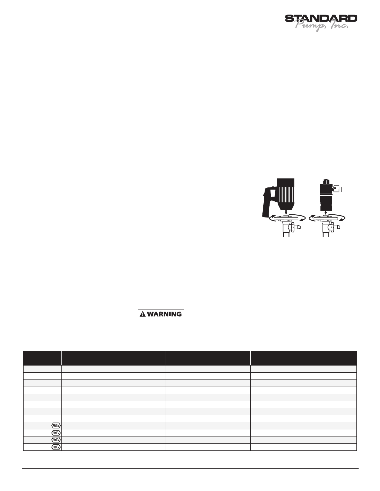
3. Couple the motor to the pump tube by
using the Hand Wheel. (See figure 1).
Figure 1
Drum Pump Specications
Model
SP-CPVC CPVC 190º F (90º C) CPVC, Carbon, Hastelloy C, PVDF, PTFE 35 gpm (132 l/min) 16 psi (1,1 bar)
SP-CPVC-HH CPVC 190º F (90º C) CPVC, Carbon, Hastelloy C, PVDF, PTFE 16 gpm (60 l/min) 32 psi (2,2 bar)
SP-PP Polypropylene 130º F (55º C) PP, Carbon, Hastelloy C, PTFE 35 gpm (132 l/min) 16 psi (1,1 bar)
SP-PP-HH Polypropylene 130º F (55º C) PP, Carbon, Hastelloy C, PTFE 16 gpm (60 l/min) 32 psi (2,2 bar)
SP-PHT Polypropylene 175º F (80º C) PP, Carbon, Hastelloy C, PTFE 35 gpm (132 l/min) 16 psi (1,1 bar)
SP-PHT-HH Polypropylene 175º F (80º C) PP, Carbon, Hastelloy C, PTFE 16 gpm (60 l/min) 32 psi (2,2 bar)
SP-PVDF PVDF (Kynar®) 175º F (80º C) PVDF, Carbon, Hastelloy C, PTFE 35 gpm (132 l/min) 16 psi (1,1 bar)
SP-PVDF-HH PVDF (Kynar®) 175º F (80º C) PVDF, Carbon, Hastelloy C, PTFE 16 gpm (60 l/min) 32 psi (2,2 bar)
*SP-SS SS316 175º F (80º C) SS316, Carbon, PTFE 35 gpm (132 l/min) 16 psi (1,1 bar)
*SP-SS-HH SS316 175º F (80º C) SS316, Carbon, PTFE 16 gpm (60 l/min) 32 psi (2,2 bar)
*SP-AL Aluminum 175º F (80º C) Aluminum, Carbon, PTFE & SS316 35 gpm (132 l/min) 16 psi (1,1 bar)
*SP-AL-HH Aluminum 175º F (80º C) Aluminum, Carbon, PTFE & SS316 16 gpm (60 l/min) 32 psi (2,2 bar)
* When operating in Hazardous Duty applications a pump must be used in conjunction with an explosion proof motor or air motor.
Material of
Construction
Maximum Liquid
Temperature
Wetted Materials Maximum Flow Rate
1
Discharge
Pressure

Standard Pump Operating Instructions and Parts Manual (OIPM-IND-0713)
Industrial Drum Pumps Models:
SP-PP, SP-PHT, SP-CPVC, SP-AL, SP-PVDF & SP-SS
Pump Package Specications
Electric Motor Pump Packages
Model HP Voltage Phase Meter Wetted Components
9400 1 110V 1 No Polypropylene, Carbon, Hastelloy C, PVC, Viton®, PTFE 39" (1000 mm) 6 ft. (1,83 meters) Polypropylene
9401 1 220V 1 No Polypropylene, Carbon, Hastelloy C, PVC, Viton®, PTFE 39" (1000 mm) 6 ft. (1,83 meters) Polypropylene
9402 1 110V 1 No Polypropylene, Carbon, Hastelloy C, PVC, Viton®, PTFE 47" (1200 mm) 6 ft. (1,83 meters) Polypropylene
9403 1 220V 1 No Polypropylene, Carbon, Hastelloy C, PVC, Viton®, PTFE 47" (1200 mm) 6 ft. (1,83 meters) Polypropylene
9414 1 110V 1 No SS316, PTFE, Carbon, PVC, PTFE 39" (1000 mm) 6 ft. (1,83 meters) SS316
9415 1 220V 1 No SS316, PTFE, Carbon, PVC, PTFE 39" (1000 mm) 6 ft. (1,83 meters) SS316
9416 1 110V 1 No SS316, PTFE, Carbon, PVC, PTFE 47" (1200 mm) 6 ft. (1,83 meters) SS316
9417 1 220V 1 No SS316, PTFE, Carbon, PVC, PTFE 47" (1200 mm) 6 ft. (1,83 meters) SS316
9420 1 110V 1 No PVDF, Carbon, Hastelloy C, Alphasyn, Viton®, PTFE 39" (1000 mm) 6 ft. (1,83 meters) PVDF
9421 1 220V 1 No PVDF, Carbon, Hastelloy C, Alphasyn, Viton®, PTFE 39" (1000 mm) 6 ft. (1,83 meters) PVDF
9422 1 110V 1 No PVDF, Carbon, Hastelloy C, Alphasyn, Viton®, PTFE 47" (1200 mm) 6 ft. (1,83 meters) PVDF
9423 1 220V 1 No PVDF, Carbon, Hastelloy C, Alphasyn, Viton®, PTFE 47" (1200 mm) 6 ft. (1,83 meters) PVDF
9430 1 110V 1 No
9431 1 220V 1 No
9432 1 110V 1 No
9433 1 220V 1 No
9500 1 110V 1 Ye s
9501 1 220V 1 Ye s
9502 1 110V 1 Ye s
9503 1 220V 1 Ye s
9510 1 110V 1 Ye s
9511 1 220V 1 Ye s
9512 1 110V 1 Ye s PVDF, Carbon, Hastelloy C, Alphasyn, PTFE 47" (1200 mm) 6 ft. (1,83 meters) PVDF
9513 1 220V 1 Ye s
9460 1 110V 1 No Aluminum, Carbon, PTFE & SS316 39" (1000 mm) 6 ft. (1,83 meters) Aluminum
9461 1 220V 1 No Aluminum, Carbon, PTFE & SS316 39" (1000 mm) 6 ft. (1,83 meters) Aluminum
9462 1 110V 1 No Aluminum, Carbon, PTFE & SS316 47" (1200 mm) 6 ft. (1,83 meters) Aluminum
9463 1 220V 1 No Aluminum, Carbon, PTFE & SS316 47" (1200 mm) 6 ft. (1,83 meters) Aluminum
9610 1 110V 1 No SS316, Carbon, PTFE 39" (1000 mm) 6 ft. (1,83 meters) SS316
9611 1 220V 1 No SS316, Carbon, PTFE 39" (1000 mm) 6 ft. (1,83 meters) SS316
9612 1 110V 1 No SS316, Carbon, PTFE 47" (1200 mm) 6 ft. (1,83 meters) SS316
9613 1 220V 1 No SS316, Carbon, PTFE 47" (1200 mm) 6 ft. (1,83 meters) SS316
CPVC, Polypropylene, Carbon, Hastelloy C, PVC,
Viton®, PVDF, PTFE
CPVC, Polypropylene, Carbon, Hastelloy C, PVC,
Viton®, PVDF, PTFE
CPVC, Polypropylene, Carbon, Hastelloy C, PVC,
Viton®, PVDF, PTFE
CPVC, Polypropylene, Carbon, Hastelloy C, PVC,
Viton®, PVDF, PTFE
Polypropylene, Carbon, Hastelloy C, PVC, Viton®,
Ceramic, PVDF, Halar, PTFE
Polypropylene, Carbon, Hastelloy C, PVC, Viton®,
Ceramic, PVDF, Halar, PTFE
Polypropylene, Carbon, Hastelloy C, PVC, Viton®,
Ceramic, PVDF, Halar, PTFE
Polypropylene, Carbon, Hastelloy C, PVC, Viton®,
Ceramic, PVDF, Halar, PTFE
PVDF, Carbon, Hastelloy C, Alphasyn, Viton®, Ceramic,
Halar, PTFE
PVDF, Carbon, Hastelloy C, Alphasyn, Viton®, Ceramic,
Halar, , PTFE
PVDF, Carbon, Hastelloy C, Alphasyn, Viton®, Ceramic,
Halar, PTFE
Immersion
Length
39" (1000 mm) 6 ft. (1,83 meters) Polypropylene
39" (1000 mm) 6 ft. (1,83 meters) Polypropylene
47" (1200 mm) 6 ft. (1,83 meters) Polypropylene
47" (1200 mm) 6 ft. (1,83 meters) Polypropylene
39" (1000 mm) 6 ft. (1,83 meters) Polypropylene
39" (1000 mm) 6 ft. (1,83 meters) Polypropylene
47" (1200 mm) 6 ft. (1,83 meters) Polypropylene
47" (1200 mm) 6 ft. (1,83 meters) Polypropylene
39" (1000 mm) 6 ft. (1,83 meters) PVDF
39" (1000 mm) 6 ft. (1,83 meters) PVDF
47" (1200 mm) 6 ft. (1,83 meters) PVDF
Hose Length
Nozzle
Material
Air Motor Pump Packages
Model HP Air Consumption Meter Wetted Components Immersion Length Hose Length Nozzle Material
9604 0.5 22 CFM (10.4 L/sec) @ 90 psi (6,2 ba r) No SS316, PTFE, Carbon, UHMWPE, PTFE 39" (1000 mm) 6 ft. (1,83 meters) SS316
9605 0.75 28 CFM (13.2 L/sec) @ 90 psi (6,2 bar) No SS316, PTFE, Carbon, UHMWPE, PTFE 39" (1000 mm) 6 ft. (1,83 meters) SS316
9606 0.05 22 CFM (10.4 L/sec) @ 90 psi (6,2 bar) No SS316, PTFE, Carbon, UHMWPE, PTFE 47" (1200 mm) 6 ft. (1,83 meters) SS316
9607 0.75 28 CFM (13.2 L/sec @ 90 psi (6,2 bar) No SS316, PTFE, Carbon, UHMWPE, PTFE 47" (1200 mm) 6 ft. (1,83 meters) SS316
9464 0.75 28 CFM (13.2 L/sec @ 90 psi (6,2 bar) No Aluminum, Carbon, PTFE & SS316 39" (1000 mm) 6 ft. (1,83 meters) Aluminum
9465 0.75 28 CFM (13.2 L/sec @ 90 psi (6,2 bar) No Aluminum, Carbon, PTFE & SS316 47" (1200 mm) 6 ft. (1,83 meters) Aluminum
®
Viton is a registered trademark of DuPont Dow Elastomers.
2
Standard Pump Operating Instructions and Parts Manual (OIPM-IND-0713)
Industrial Drum Pumps Models:
SP-PP, SP-PHT, SP-CPVC, SP-AL, SP-PVDF & SP-SS
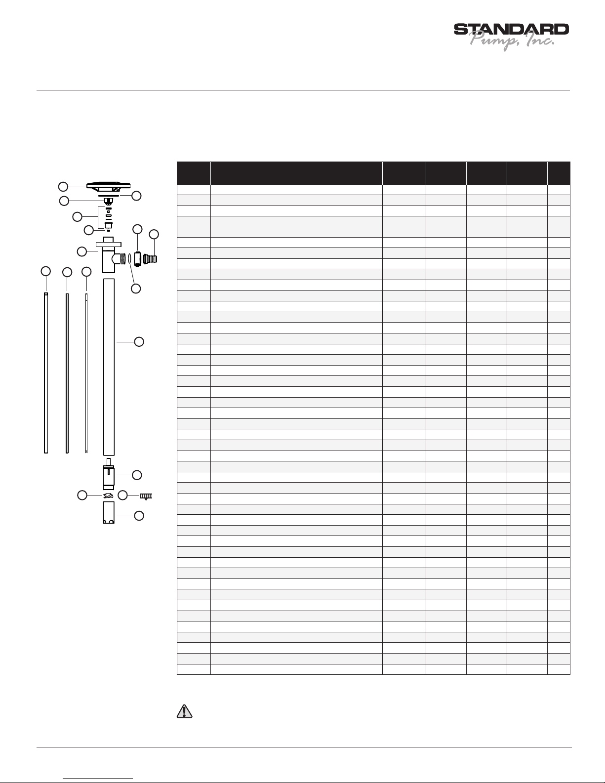
SP-PP, SP-PHT, SP-CPVC, SP-PVDF Spare Parts List
Ref.
1
2
4
5
3
9
10
Number
1 Hand Wheel, Polypropylene 1842 1842 1842 1842 1
2 Pump Coupling, Nylon 1004* 1004* 1004* 1004* 1
3 Snap Ring, Steel 1508 1508 1508 1508 1
Bearing Unit Assembled – 2 each
4
Viton shielded bearings, spacer, snap ring, bearing can
5 V-Seal, Viton
8
11
6
7
18
V-Seal, PTFE - 4000 4000 4000
6 Drive Shaft, Hastelloy
27" (700 mm) 1543 1543 1543 1543 1
39" (1000 mm) 1544 1544 1544 1544 1
Description
®
P/N for
SP-PP
P/N for
SP-PHT
P/N for
SP-CPVC
P/N for
SP-PVDF
1038* 1038* 1038* 1038* 1
1000 - - - 1
Qty
47" (1200 mm) 1545 1545 1545 1545 1
50" (1270 mm) 1549 1549 1549 1549 1
60" (1500 mm) 1546 1546 1546 1546 1
72" (1800 mm) 1547 1547 1547 1547 1
12
7 Guide Sleeve, PTFE
27"(700 mm) 1516 1516 1516 1516 1
39" (1000 mm), 47" (1200 mm), 50" (1270 mm) 1514 1514 1514 1514
60" (1500 mm), 72" (1800 mm) 1661 1661 1661 1661 1
8 Discharge Housing 1028 6028 5028 4028 1
9 Wing Nut 1106 6106 5106 4106 1
10 Hose Barb
.75" (19 mm) 1051 6051 5051 4051 1
1" (25 mm) 1082 6082 5082 4082 1
11 Inner Tube,
27" (700 mm) 1600 6600 5600 4600 1
39" (1000 mm) 1601 6601 5601 4601 1
47" (1200 mm) 1602 6602 5602 4602 1
50" (1270 mm) 1623 6623 5623 4623 1
60" (1500 mm) 1615 6615 5615 4615 1
72" (1800 mm) 1616 6616 5616 4618 1
27" (700 mm) 1604 6604 5604 4604 1
14 15
13
16
12 Outer Tube,
39" (1000 mm) 1603 6603 5603 4603 1
47" (1200 mm) 1605 6605 5605 4605 1
50" (1270 mm) 1624 6624 5624 4622 1
60" (1500 mm) 1617 6617 5617 4617 1
72" (1800 mm) 1618 6618 5618 4619 1
13 Pump Housing (Includes Carbon Bushing) 1524* 6524* 5524* 4607* 1
14 High Volume Impeller, Polypropylene 1608* 6608* 5608* 4608* 1
15 High Pressure Impeller, PTFE 4608 HH 4608 HH 4608 HH 4608 HH 1
16 High Volume Pump Foot, Polypropylene 1609* 6609* - - 1
High Volume Pump Foot, PVDF - - 5609* 4609* 1
High Pressure Pump Foot, Polypropylene & PTFE 1609 HH 6609 HH - - 1
High Pressure Pump Foot, PVDF & PTFE - - 5609 HH 4609 HH 1
17 Repair Kit (*Includes Items 2, 5, 10, 13, & 14) 9050 9053 9052 9051 1
18 O-Ring, Viton
®
- 6695 - - 1
SP-PP, SP-PHT, SP-CPVC, SP-PVDF pumps should not be used to pump flammables.
3

Standard Pump Operating Instructions and Parts Manual (OIPM-IND-0713)
Industrial Drum Pumps Models:
SP-PP, SP-PHT, SP-CPVC, SP-AL, SP-PVDF & SP-SS
10
11
9
12
SP-AL Spare Parts List
Ref.
Number
Description
P/N for
SP-AL
Qty
1 Hand Wheel, Polypropylene 1842 1
13
1
2
3
4
5
6
2 Snap Ring, Steel 1508 1
3 Pump Coupling, Nylon 1004* 1
Bearing Unit Assembled - 2 each Viton® Shielded Bearings,
4
Spacer, Snap Ring, Bearing Can
1038* 1
5 V-Seal, PTFE 4000 1
6 Connection Flange, Aluminum 3723 1
7 Drive Shaft, SS316
27" (700 mm) 2027 1
39" (1000 mm) 2028 1
47" (1200 mm) 2029 1
60" (1500 mm) 2709 1
72" (1800 mm) 2710 1
8 Guide Sleeve, PTFE
7
27" (700 mm) 2031 1
39" (1000 mm) / 47" (1200 mm) 2032 1
60" (1500 mm) 2711 1
72" (1800 mm) 2712 1
8
14
9 Discharge Housing, Aluminum 3724 1
10 Seal, PTFE 2195* 1
11 Wing Nut, Aluminum 3709 1
12 Hose Barb, Aluminum
.75" (19 mm) 3708 1
1" (25 mm) 3707 1
13 Inner Tube, Aluminum
27" (700 mm) 3712 1
39" (1000 mm) 3714 1
47" (1200 mm) 3716 1
60" (1500 mm) 3718 1
72" (1800 mm) 3720 1
14 Seal, PTFE 730 1
15 Outer Tube, Aluminum
27" (700 mm) 3713 1
39" (1000 mm) 3715 1
15
47" (1200 mm) 3717 1
60" (1500 mm) 3719 1
72" (1800 mm) 3721 1
16 O-Ring, Viton (2 per set) 2707 1
17 Pump Housing, Aluminum 3725* 1
(Includes Carbon Bushing)
18 High Volume Impeller, PTFE 2706* 1
16
17
18
19
19 High Pressure Impeller, PTFE 4608HH 1
20 High Volume Pump Foot, Aluminum 3726 1
High Pressure Pump Foot, Aluminum 3726HH 1
21 Repair Kit (*Includes Items 3,4,10,17 & 18) 9057 1
20
When pumping flammables or combustible liquids, this pump must be used in conjunction with an explosion proof motor.
4

Standard Pump Operating Instructions and Parts Manual (OIPM-IND-0713)
Industrial Drum Pumps Models:
SP-PP, SP-PHT, SP-CPVC, SP-AL, SP-PVDF & SP-SS
SP-SS Spare Parts List
Ref.
Number
1
3
4
5
7
2
9
11
10
1 Hand Wheel, Polypropylene 1842 1
2 Snap Ring, Steel 1508 1
3 Pump Coupling, Nylon 1004* 1
4 Bearing Unit Assembled – 2 each 1038* 1
Viton® shielded bearings, spacer, snap ring, bearing can
5 V-Seal, PTFE 4000 1
6 Drive Shaft, SS316
27" (700 mm) 2027 1
39" (1000 mm) 2028 1
Description
P/N for
SP-SS
Qty
47" (1200 mm) 2029 1
60" (1500 mm) 2709 1
72" (1800 mm) 2710 1
6
12
8
7 Connection Flange, SS316 8102 1
8 Guide Sleeve, PTFE
27" (700 mm) 2031 1
39" (1000 mm) / 47" (1200 mm) 2032 1
60" (1500 mm) 2711 1
72" (1800 mm) 2712 1
9 Wing Nut, SS316 8068 1
10 Seal, PTFE 2195 1
11 Hose Barb, SS316
.75" (19 mm) 2197 1
1" (25 mm) 2196 1
12 Inner/Outer Tube Assembly, SS316
13
27" (700 mm) 2700 1
39" (1000 mm) 2701 1
14 15
16
13 Pump Housing with Carbon Bushing, SS316 2704* 1
47" (1200 mm) 2702 1
60" (1500 mm) 2713 1
72" (1800 mm) 2714 1
14 High Volume Impeller, PTFE 2706*
15 High Pressure Impeller, PTFE 4608 HH 1
14 O-Ring, Viton (2 per set) 2707 1
16 High Volume Pump Foot, SS316 2708 1
High Pressure Pump Foot, SS316 2708 HH 1
17 Repair Kit (*Includes Items 1, 2, 9, 12 & 13) 9054 1
When pumping flammables or combustible liquids, this pump must be used in conjunction with an explosion proof motor.
5
Standard Pump Operating Instructions and Parts Manual (OIPM-IND-0713)
Industrial Drum Pumps Models:
SP-PP, SP-PHT, SP-CPVC, SP-AL, SP-PVDF & SP-SS
Hazardous Duty
Operation
When pumping
flammable or
combustible products or operating in a
hazardous duty environment, the
SP-8600, SP-8700, SP-8800, SP-8900,
SP-AL or SP-SS Series pump must be
used in conjunction with an explosion
proof motor. Please contact the factory
or an authorized distributor with any
questions regarding this matter.
SP-420 EX & SP-A1 Series
When operating in Hazardous Duty
applications SP-420EX or SP-A1 must
be used in conjunction with an SP-SS,
SP-AL, SP-8600 or SP-8800 Series pump
and properly bonded and grounded. Refer
to the Motor specification chart for motor
information.
Special Conditions for
Safety Use
• Only for conductive liquids (gases groups IIA
and IIB).
• The flashpoint for the flammable media
shall be 50°C higher than the maximum
temperature T4 (135°C).
• The SP-AL versions may not be used in an
area where rusty particles or rusty iron is
present.
• The tube shall regular be inspected for
damage and corrosions. If there is any
damage or corrosions the equipment and the
tube shall be taken out of service.
• The grounding clamp and wire on the pump
shall be connected to the liquid container
before and after pump start.
• The pumps must not be exposed to pumping
hard solid particles which can create sparks.
• Demands for inspections, maintenance and
repair according to the instructions.
• The pump is only for hand held operation and
may not be running dry.
• The SP-AL version may only be used with
the PTFE impeller parts no. 2706 and
4608HH.
Drum Pump Installation
SP-410EX
• Install the Pump and Static Protection Kit as
described in Figure 2 on page 7.
• Connect Ground Wire assembly to earth
ground using supplied clamp.
• Connect Ground Wire between drum and
earth ground.
• Connect Ground Wire between receiving
container and earth ground (or use bonding
wire to connect to drum).
Check electrical
continuity of all
components before pumping. All should
be one (1) ohm or less.
Operation and Safety
Guidelines
• Use only metallic pump tubes with
explosion proof motors to transfer
flammable or combustible liquids.
• Area for use must comply with NFPA 30
guidelines for safe storage and use of
flammable and combustible liquids.
• All containers and other equipment must be
metal and grounded.
• Follow NGPA 77 guidelines for control of
static electricity.
• Avoid splashing. Splash filling can create
static electricity and is extremely hazardous.
• Fluid velocity must be 3 feet/second (0.91
meters/second) maximum 7 GPM in 1"
hose (26.5 LPM in 25 mm hose).
Use Of Air Motors In
Hazardous Atmospheres
SP-A1 Series & SP-A2 Series
At the present time, there are no known
standards governing the operation of air
motors in hazardous atmospheres. However,
there are several points regarding the safety
of air motors.
First of all, an air motor is not a source of
electric sparks. However, it is possible that
an article which is not part of the air motor
(e.g., wrenches, hammers, etc.) could create
a spark by sharply impacting a cast iron or
aluminum case or the steel shaft of the air
motor. (Note that electric motor enclosures
for both class I and II hazardous locations
can be made of “...iron, steel, copper, bronze,
or aluminum..." (UL 674, Electric Motors and
Generators – Hazardous Locations, June 23,
1989; paragraph 4.2, page 6).Second, an air
motor housing is not designed to contain an
internal explosion as is an explosion-proof
electric motor. The only possible internal
source of ignition in an air motor is a contact
between the station housing components
and the rotating elements that might create
a spark. The likelihood of this occurring is
reduced by the fact that the contact must
be made at precisely the same time as a
flammable or explosive gas is introduced
into the air motor in a sufficient quantity to
achieve a flammable or explosive mixture
while overcoming the positive pressure of
the driving gas. In other words, although
highly improbable, an internal explosion in an
air motor is possible. Finally, an air motor is
designed to be operated by compressed air,
the expansion of which in normal operation
creates a cooling effect. As a result, the
temperature of the air motor will not exceed
the height of the temperatures of the
surrounding atmosphere or the air delivered
to the inlet.
We do not guarantee the safety of every
application, but to ensure the safe operation
of an air motor in your application, always
follow the product direction and consult
with a qualified engineer. (Source: Gast
Manufacturing, Air Motors Handbook, page
2) Note: This statement is only applicable in
North America.
When using an SP-A1
or SP-A2 Series motor,
Standard Pump recommends the use of a
Filter Lubricator Regulator (FLR) in order
to ensure a moisture free supply of air to
the motor.
SP-A1 and SP-A2
Series motors must be
lubricated daily to ensure proper
functionality
Grounding Procedures
Transferring of
flammables or use in
hazardous duty. Bonding is an electrical
connection between a primary metal vessel
and a metal receiving vessel. See schematic.
Grounding is an electrical connection
between a metal vessel, pump, motor and a
constant ground; i.e. a metal rod driven into
the earth.
Bonding and grounding are required when
pumping flammable materials or in hazardous
duty environments. Failure to bond and
ground properly can cause a discharge of
static electricity resulting in fire, injury or
death. Follow NFPA 77 and 30 procedures
at all times. If in doubt, do not start pump!
Be sure bonding and grounding wires are
secure before starting operation. (Ground
and bond wires must have less than one ohm
resistance for safe usage. Check continuity
before starting). Always check with a safety
engineer when any question arises and
periodically check safety procedures with a
safety engineer (see Figure 2, page 7).
6

Standard Pump Operating Instructions and Parts Manual (OIPM-IND-0713)
Industrial Drum Pumps Models:
SP-PP, SP-PHT, SP-CPVC, SP-AL, SP-PVDF & SP-SS
Grounding Procedures
(Continued)
Air Line
Exhaust Line
Ground Wire
(Not Included)
Rod
Earth Ground
Figure 2 - Static Protection Kit
Bond Wire
(Not Included)
Optionals:
Solvent resistant safety
hose with ground wire
Metal Drum
No Splashing
Ground Wire
Rod
Earth Ground
Bond Wire
Solvent resistant safety
hose with wir
e ground
Metal Drum
Air MotorElectric Motor
7

Standard Pump Operating Instructions and Parts Manual (OIPM-IND-0713)
Industrial Drum Pumps Models:
SP-PP, SP-PHT, SP-CPVC, SP-AL, SP-PVDF & SP-SS
8

Standard Pump Operating Instructions and Parts Manual (OIPM-IND-0713)
Warranty
Declarations
Declaration of Conformity When this unit is used as a stand alone unit it complies with:
Machinery Directive 98/37/EC EN60204,
EN60335-2-41, EN60335-1, Low Voltage Directive 73/23/Eec
EN61010-1, EMC Directive 89/336/Eec EN55014, EN 550104,
EN50081-1, EN50082-1
Declaration of Incorporation When this pump unit is to be installed into machine
or is to be assembled with other machines for
installations, it must not be put into service until
the relevant machinery has been declared in
conformity with Machine Directive 98/37/EC
EN60204, EN60335-2-41, EN60335-1.
Responsible person: Donald M. Murphy, President, Standard Pump, Inc.
1540 University Drive, Auburn, Georgia 30011
Ph: 001-770-307-1003 Fax: 001-770-307-1009
e-mail: info@standardpump.com
www.standardpump.com
Three year limited warranty
Standard Pump, Inc. warrants, subject to the conditions below, through either Standard Pump, Inc., it’s subsidiaries, or
its authorized distributors, to repair or replace free of charge, including labor, any part of this equipment which fails within
three years of delivery of the product to the end user. Such failure must have occurred because of defect in material or
workmanship and not as a result of operation of the equipment other than in accordance with the instructions given in this
material. Specic exceptions include:
• Consumable items such as motor brushes, bearings, couplings and impellers. (Motor brushes typically have a life
span of approximately 700 hours. This will vary with the manner in which the motor is used)
Conditions of exceptions include:
• Equipment must be returned by prepaid carriage to Standard Pump, Inc., its subsidiary or authorized distributor.
• All repairs, modications must have been made by or with express written permission by Standard Pump, Inc.,
it’s subsidiary or authorized distributor.
• Equipment which have been abused, misused, or subject to malicious or accidental damage or electrical surge are
excluded.
Warranties purporting to be on behalf of Standard Pump, Inc. made by any person, including representatives of Standard
Pump, Inc, its subsidiaries, or its distributors, which do not fall within the terms of this warranty shall not be binding upon
Standard Pump, Inc. unless expressly approved in writing by a Director or Manager of Standard Pump, Inc. Information for
returning pumps Equipment which has been contaminated with, or exposed to, bodily uids, toxic chemicals or any other
substance hazardous to health must be decontaminated before it is returned to Standard Pump, Inc, or its distributor. A
returned goods authorization number (RGA #) issued by Standard Pump, Inc., its subsidiary or authorized distributor, must
be included with the returned equipment. The RGA # is required if the equipment has been used. If the equipment has
been used, the uids that have been in contact with the pump and the cleaning procedure must be specied along with a
statement that the equipment has been decontaminated.
1540 University Drive, Auburn, Georgia 30011 USA
TOLL FREE 1-866-558 -8611 • Phone 770–307–1003 • Fax 770–307–1009
STANDARD PUMP
e-mail: info@standardpump.com
www.standardpump.com
9
 Loading...