

Standard Pump SP-800DD, SP-800SR, SP-8900, SP-8800, SP-8200 Operating Instructions And Parts Manual
...
Standard Pump Operating Instructions and Parts Manual (OIPMS0611)
Operating Instructions and Parts Manual
Sanitary Pump Models: SP-8100, SP-8200, SP-8800, SP-8900
SP-800SR & SP-800DD
Metering Systems Models: 8300, 8320 & 8500
TABLE OF CONTENTS
PAGE
General Safety Information .....................................................2
SP-8100 & SP-8200 Series .......................................................2
SP-8800 & SP-8900 Series .......................................................6
SP-800SR Series ..............................................................10
SP-800DD Series ..............................................................11
Ultra Mass 8500 Series .........................................................16
Ultra Mag 8300 Series..........................................................18
Flow Meter & Pump Systems 8320 Series ...........................................20
Motors .....................................................................22
Hazardous Duty Environments...................................................26
Warranty ...................................................................27
3-A Certificate ...............................................................28
1540 University Drive, Auburn, Georgia 30011 USA
TOLL FREE 866–558–8611 • Phone 770–307–1003 • Fax 770–307–1009
(OIPMS0611)
STANDARD PUMP
e-mail: info@standardpump.com
www.standardpump.com
1
Standard Pump Operating Instructions and Parts Manual (OIPMS0611)Standard Pump Operating Instructions and Parts Manual (OIPMS0611)
Standard Pump
Sanitary Pump Models:
SP-8100, SP-8200, SP-8800, SP-8900, SP-800SR & SP-800DD
Description
Standard’s Drum Pumps are designed to transfer a variety of
materials from 55 gallon drums and tanks. Standard Pump
offers several different pumps, each designed for specific
applications. Before operating, please confirm that the pump’s
materials of construction are suitable for the application.
Unpacking
Cartons should be handled with care to avoid damage from
dropping, etc. After unpacking, inspect carefully for any
damage that may have occurred during transit. Check for
loose, damaged or missing parts.
General Safety Information
The responsibility for safe assembly, installation, and operation
ultimately rests with the operator. Read and understand ALL
safety precautions and operating instructions before operation.
Careless pump operation can result in serious injury.
1. Before operating the pump, read and understand these
operating instructions.
2. The operator should wear suitable protective clothing
including the following: face mask, safety shield or
goggles, gloves, apron, and safety shoes.
3. Before operating, verify the materials being pumped are
compatible with the pump’s “wetted components.”
4. All Federal, State, and local safety codes should be
followed.
5. Verify that the motor voltage corresponds to proper
electrical supply.
6. Before plugging motor into power supply, make sure the
motor switch is in the OFF position.
7. Before operation, confirm all pump connections are
properly tightened.
8. First pump clean water in order to familiarize yourself with
the pump’s operation, flow rate, discharge pressure and
motor speed.
9. Before starting the pump, confirm the discharge hose is
securely fastened to the receiving vessel in order to prevent
splashing.
10. Never leave pump unattended during operation.
11. Do not submerge the motor in any liquid.
12. When finished using the pump, flush the pump by
pumping water or an appropriate cleaning solution. Do not
use flammable or combustible cleaning solutions.
13. Never carry the motor by the power cord.
SP-8100 & SP-8200 SERIES
Specifications
Models SP-8100 & SP-8200
Maximum Liquid
Temperature ....................175º F (79º C)
Pump Type .......................Centrifugal
Pump Speed .....................10,000 RPM
Max. Flow Rate SP-8100 .................. 32 GPM (121 LPM)
SP-8200 .................... 15 GPM (57 LPM)
Max. Discharge Pressure SP-8100 ........................ 16 psi (1,1 bar)
SP-8200 ........................ 32 psi (2,2 bar)
Wetted Materials ............SS 316, Buna & Teflon
Immersion Length ........... 47" (1200 mm) (Tanks)
39" (1000 mm) (Drums & Barrels)
Discharge Port .................... 1.0" (25 mm) Hose Barb &
1.5" (38 mm) Tri-Clamp
Motors .............................SP-280P Series, SP-ENC Series,
SP-A1FP, SP-A2 Series
Note: Flow rates are based on water. As viscosity increases, the flow
rate will decrease.
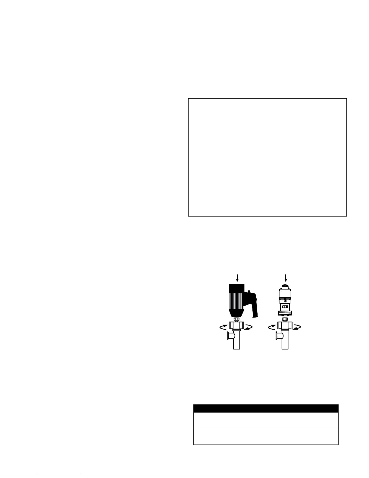
Assembly
1. Remove the pump and motor from packaging.
2. Inspect all contents for damage.
3. Couple the motor to the pump tube by using the Hex Nut
(see Figure 1).
Electric
Figure 1
4. It is recommended to thoroughly clean and sanitize models
SP-8100 & SP-8200 before operation.
5. First pump clean water in order to familiarize yourself with
the pump’s operation, flow rate, discharge pressure and
motor speed.
Model Air Connection Consumption
SP-A1FP .125" (3,2 mm) 28 CFM @ 90 psi
13.2 L/sec @ 6,2 bar
SP-A2L .25" (6,3 mm) 28 CFM @ 90 psi
SP-A2 13.2 L/sec @ 6,2 bar
Note: For optimum performance make sure proper size air
lines are installed.
2
Air
Standard Pump Operating Instructions and Parts Manual (OIPMS0611)
Do not use these pumps for the transfer of
flammable or combustible products or in an
environment where flammable or combustible fumes are
present unless used in conjunction with an Explosion Proof
Motor, SP-A1FP or SPA2 Series air motor. Please contact the
factory or authorized distributor with any questions regarding
this matter (see page 24).
General Operation Guide (SP-8100 & SP-8200)
1. Use closed top drum or other cover to prevent possible
contamination.
2. Once the pump is fully cleaned, assembled and all
connections are securely fastened, insert the pump into the
drum or tank.
Air Line
Air Exhaust
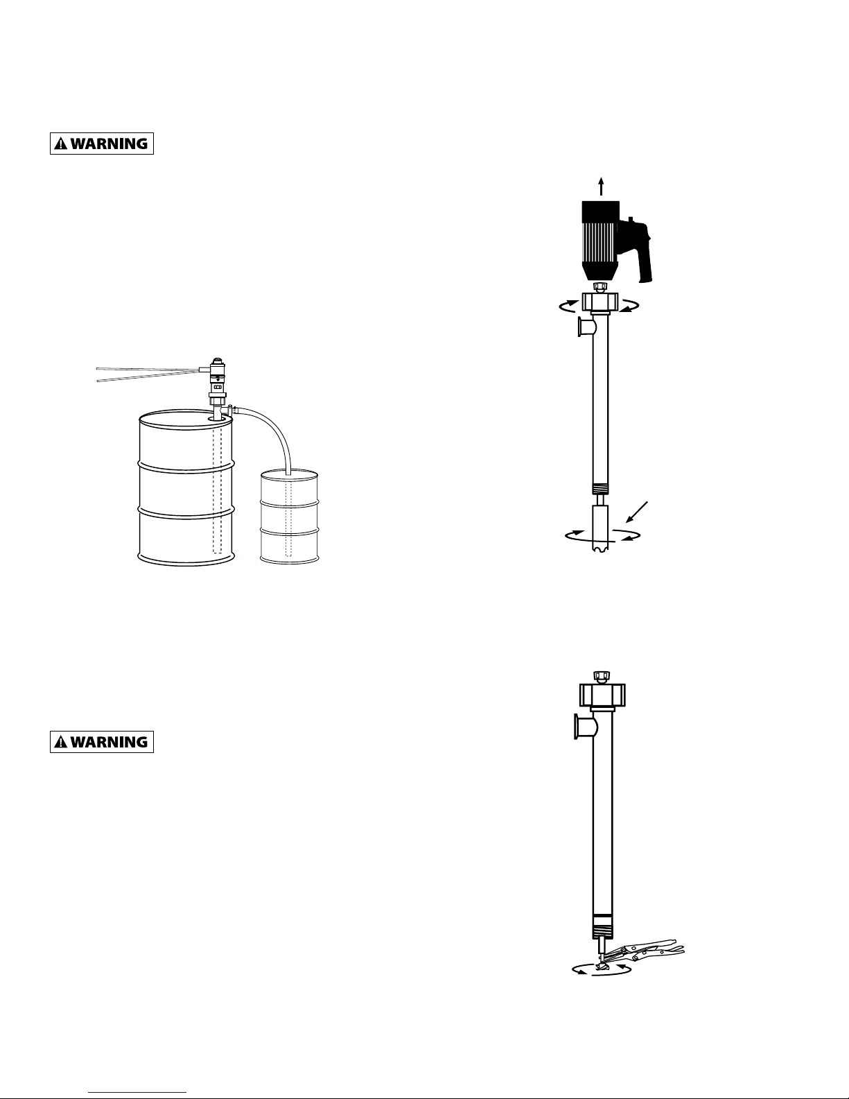
3. Remove the pump foot (P/N: 8108 or 8108HH) by turning
clockwise (see Figure 2).
Pump Foot
Note: Recommend plumbing exhaust air away from drum or
tank to avoid possible contamination. Left port is air intake,
right port is air exhaust.
3. It is recommended to attach a suitable hose or pipe to the
pump discharge.
4. If you opt to use a hose, fasten the hose to the hose
barb with a suitable hose clamp that exceeds the pump
discharge pressure.
Make sure the hose meets the pump
discharge pressure requirements (SP-8100
= 16 psi (1,1 bar)) / (SP-8200 = 32 psi (2,2 bar). It is
recommended to use a hose that is rated 4 x the pump
discharge pressure.
Ex: 32 x 4 = 128 psi (9 bar).
5. Turn the motor to the “ON” position.
6. After use, clean the pump and store vertically.
Disassembly / Cleaning Procedures
(SP-8100 & SP-8200)
1. In order to clean a majority of the residue from the pump
tube, immerse the pump into a 55 Gallon Drum of water
or a non-flammable, food safe cleaning agent. Allow the
pump to circulate the water for 3 minutes.
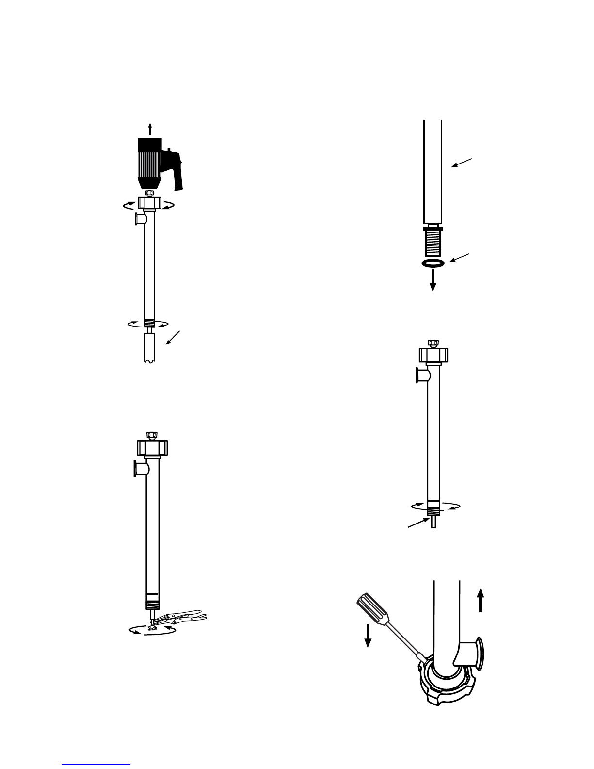
2. For a more thorough cleaning remove the motor from the
pump tube by loosening the connection nut (P/N: 8842)
(see Figure 2).
Figure 2
4. While holding the drive shaft (P/N: 2028 or 2029) with
pliers (Factory suggests grip-locks to avoid scarring shafts)
remove the impeller (P/N: 2706 or 4608HH) (see Figure 3).
Figure 3
NOTE: Use grip-lock pliers to hold shaft while removing
impeller counter clockwise.
3
Standard Pump Operating Instructions and Parts Manual (OIPMS0611)
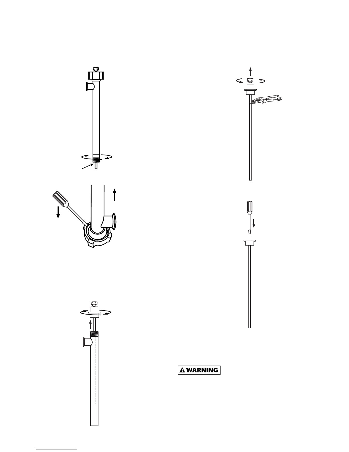
5. Remove the Pump Housing (P/N: 8107) by turning clockwise
(see Figure 4).
Figure 4
6. Remove the connection nut (P/N: 8842) (see Figure 5).
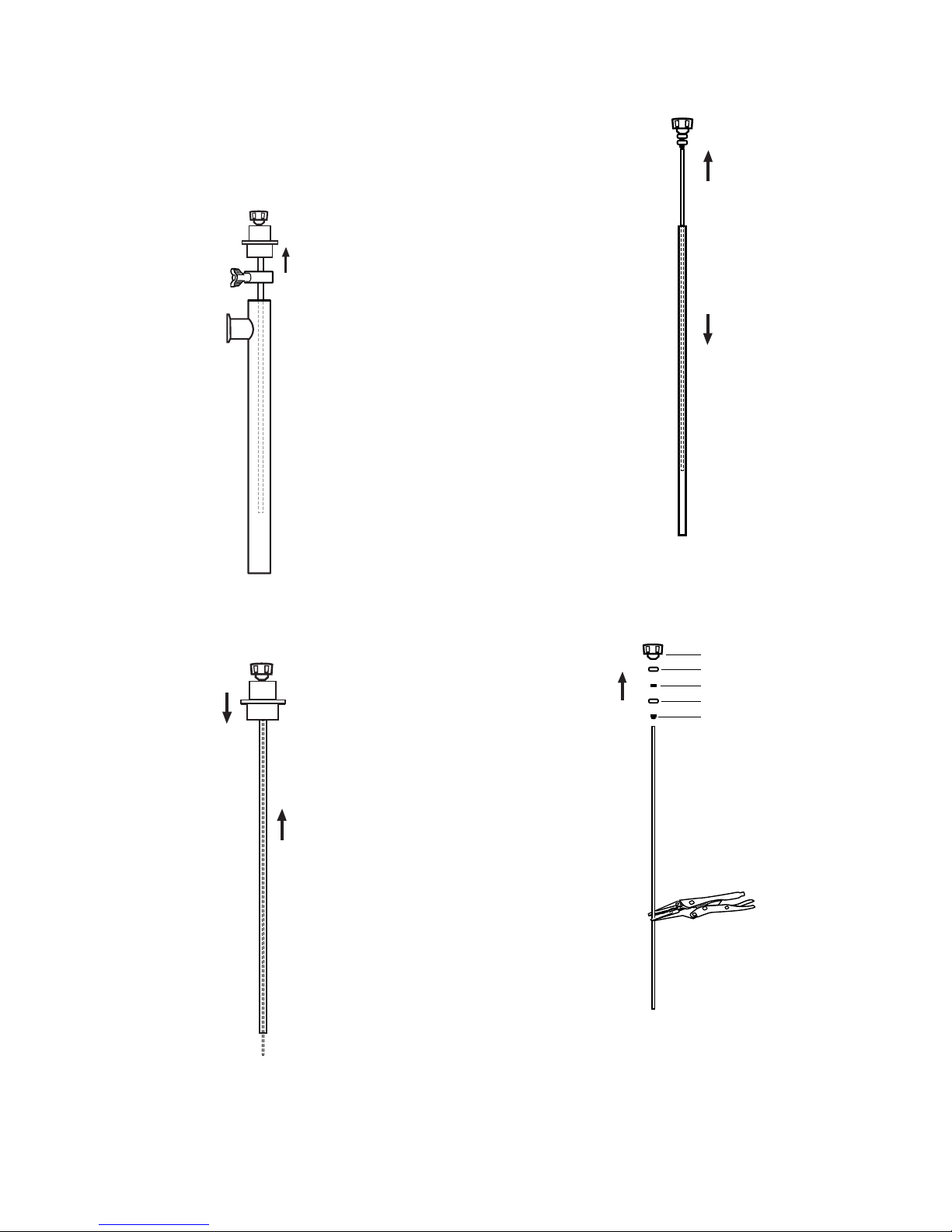
8. Secure drive shaft (P/N: 2028 or 2029) with grip-locks. Remove
coupling counter clockwise (P/N: 1004) (see Figure 7).
Figure 7
9. Insert screwdriver through bearing unit (P/N: 1038) (see
Figure 8).
Figure 5
7. Loosen connection flange from inner/outer assembly
by turning clockwise. Pull straight up separating the
connection flange (P/N: 8102) and drive shaft (P/N: 2028 or
2029) from the inner / outer tube assembly (P/N: 8104 or P/N:
8105) (see Figure 6).
Figure 6
Figure 8
NOTE: Ensure screwdriver is maintained inside bearing unit
so spacer and seal are stationary and aligned properly for
reassembly.
When replacing the drive shaft in the
bearing unit (P/N: 1038) during reassembly,
make sure the drive shaft is inserted through the spacer in
between the bearings inside the bearing unit. Failure to do so
could cause the bearing unit to prematurely fail.
10. Use a non-flammable, food safe cleaning agent to
manually clean remainder of pump tube.
11. After thoroughly inspecting all components, reassemble
in the reverse order of disassembly steps. Make sure all
components are clean, secure and undamaged.
4
Standard Pump Operating Instructions and Parts Manual (OIPMS0611)
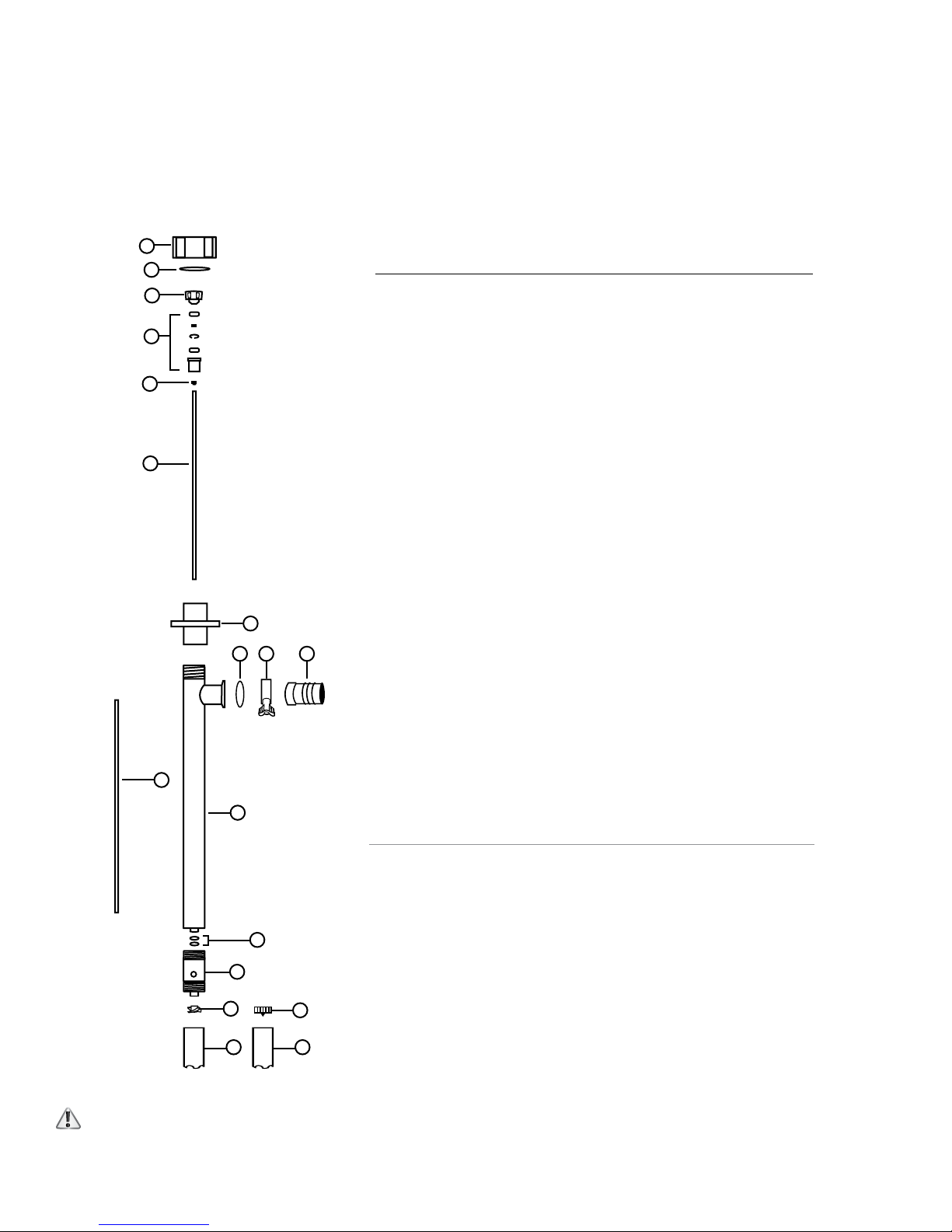
SP-8100 SERIES PARTS
SP-8200 SERIES PARTS
1
2
3
4
5
ITEM DESCRIPTION PART
NUMBER NUMBER
1
2
3
4
Connection Nut, SS316
Snap Ring, SS316
Pump Coupling
Bearing Unit Assembled — 2 each
8842
8208
1004
1038
Viton shielded bearings,
spacer, snap ring, bearing can
5
6
6
7
8
9
10
8
9
1110
11
12
13
14
15
7
16
17
12
18
V-Seal, PTFE
Drive Shaft, SS316
39" (1000 mm)
47" (1200 mm)
Guide Sleeve, PTFE
39" (1000 mm) /47" (1200 mm)
Connection Flange, SS316
O-Ring, Buna
Tri-Clamp, SS316
Hose Barb, SS316, 1" (25 mm)
Inner/Outer Tube Assembly, SS316
39" (1000 mm)
47" (1200 mm)
O-Ring, Buna (2 per set)
Pump Housing, SS316 w/ PTFE Bushing
Impeller, High Volume, PTFE (SP-8100)
Impeller, High Pressure, PTFE (SP-8200)
Pump Foot, High Volume, SS316 (SP-8100)
Pump Foot, High Pressure, SS316 (SP-8200)
4000
2028
2029
8106
8102
836
833
8833
8104
8105
8103
8107
2706
4608HH
8108
8108HH
13
14
15
17
16
18
When pumping flammable or combustible liquids, this pump must be used in conjunction with an explosion proof motor,
SP-A1FP or SP-A2 Series air motor (see page 26).
5

Standard Pump Operating Instructions and Parts Manual (OIPMS0611)
SP-8800 & SP-8900 SERIES
Specifications
Models SP-8800 & SP-8900
Maximum Liquid
Temperature ....................175º F (79º C)
Pump Type .......................Centrifugal
Pump Speed .....................10,000 RPM
Max. Flow Rate SP-8800 .................. 32 GPM (121 LPM)
SP-8900 .................... 15 GPM (57 LPM)
Max. Discharge Pressure SP-8800 ........................ 16 psi (1,1 bar)
SP-8900 ........................ 32 psi (2,2 bar)
Wetted Materials ............SS 316, Buna & Teflon
Immersion Length ........... 47" (1200 mm) (Tanks)
39" (1000 mm) (Drums & Barrels)
Discharge Port .................... 1.0" (25mm) Hose Barb &
1.5" (38 mm) Tri-Clamp
Motors .............................SP-280P Series, SP-ENC Series,
SP-A1FP, SP-A2 Series
Note: Flow rates are based on water. As viscosity increases, the flow
rate will decrease.
Assembly
1. Remove the pump and motor from packaging.
2. Inspect all contents for damage.
3. Couple the motor to the pump tube by using the Hex Nut
(see Figure 1).
Do not use these pumps for the transfer of
flammable or combustible products or in an
environment where flammable or combustible fumes are present
unless used in conjunction with an Explosion Proof Motor or
SP-A1FP / SP-A2 Series air motor. Please contact the factory or
authorized distributor with any questions regarding this matter
(see page 24).
General Operation Guide (SP-8800 & SP-8900)
1. Use closed top drum or other cover to avoid possible
contamination.
2. Once the pump is fully cleaned, assembled and all
connections are securely fastened, insert the pump into the
drum or tank.
Air Line
Air Exhaust
Electric
Figure 1
Air
4. First pump clean water in order to familiarize yourself with
the pump’s operation, flow rate, discharge pressure and
motor speed.
5. It is recommended to thoroughly clean and sanitize models
SP-8800 & SP-8900 before operation.
Model Air Connection Consumption
SP-A1FP .125" (3,2 mm) 28 CFM @ 90 psi
13.2 L/sec @ 6,2 bar
SP-A2L .25" (6,3 mm) 28 CFM @ 90 psi
SP-A2 13.2 L/sec @ 6,2 bar
Note: For optimum performance make sure proper size air
lines are installed.
Note: Recommend plumbing discharge air away from drum or
tank to prevent possible contamination. Left port is air intake,
right port is air exhaust.
3. It is recommended to attach a suitable hose or pipe to the
pump discharge.
4. If you opt to use a hose, fasten the hose to the hose
barb with a suitable hose clamp that exceeds the pump
discharge pressure.
Make sure the hose meets the pump
discharge pressure requirements (SP-8800
= 16 psi (1,1 bar)) / (SP-8900 = 32 psi (2,2 bar). It is
recommended to use a hose that is rated 4 x the pump
discharge pressure. Ex: 32 x 4 = 128 psi (9 bar).
5. Turn the motor to the “ON” position.
6. After use, clean the pump and store vertically.
Disassembly / Cleaning Procedures
(SP-8800 & SP-8900)
1. In order to clean a majority of the residue from the pump
tube, immerse the pump into a 55 Gallon Drum of water
or a non-flammable, food safe cleaning agent. Allow the
pump to circulate the water for 3 minutes.
2. For a more thorough cleaning remove the motor from the
pump tube by loosening the connection nut (P/N: 8842)
(see Figure 2).
6
Standard Pump Operating Instructions and Parts Manual (OIPMS0611)
5. Remove O-ring (P/N: 8830) from drive shaft (P/N: 8806 or 8807)
3. Remove the pump foot (P/N: 8826 or P/N: 8926) by turning
Figure 4
located behind impeller (P/N: 8827 or P/N: 8927 (see Figure 4).
Drive Shaft
O-Ring
Pump Foot
Figure 2
clockwise (see Figure 2).
4. While holding the drive shaft (P/N: 8806 or P/N: 8807) with
pliers (Factory suggests grip-locks to avoid scarring shafts)
remove the impeller (P/N: 8827 or P/N: 8927) (see Figure 3).
6. Remove the Pump Housing (P/N: 8824) by turning clockwise
(see Figure 5).
Figure 5
7. Remove the connection nut (P/N: 8842) (see Figure 6).
Figure 3
NOTE: Use grip-lock pliers to hold shaft while removing
impeller counter clockwise.
Figure 6
7
Standard Pump Operating Instructions and Parts Manual (OIPMS0611)
8. Remove tri-clamp fitting (P/N: 833).
9. Pull straight up separating the inner tube assembly (P/N:
8819 or P/N: 8820) from outer tube assembly (P/N: 8814 or
8815) (see Figure 7).
Figure 7
10. Secure inner tube assembly (P/N: 8819 or P/N: 8820). Lightly
tap drive shaft (P/N: 8806 or P/N: 8807) up through inner
tube assembly (see Figure 8).
Figure 9
12. Secure drive shaft (P/N: 8806 or P/N: 8807) with grip-
locks. Remove coupling (P/N: 1004), bearings (P/N:
1038-2),bearing spacer (P/N: 1038-4) and secondary seal
(P/N: 8803) (see Figure 10).
Coupling
Bearing
Spacer
Bearing
Seal
Figure 8
11. Remove guide sleeve (P/N: 8811) from drive shaft (P/N: 8806
or P/N: 8807) (see Figure 9).
Figure 10
13. Use a non-flammable, food safe cleaning agent to
manually clean remainder of pump tube.
14. After thoroughly inspecting all components, reassemble
in the reverse order of disassembly steps. Make sure all
components are clean, secure and undamaged.
8
Standard Pump Operating Instructions and Parts Manual (OIPMS0611)
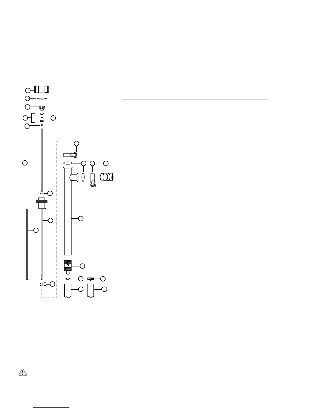
SP-8800 SERIES PARTS
SP-8900 SERIES PARTS
1
2
3
4
6
7
9
5
13
12 1413
8
10
11
15
16
17
19
18
20
ITEM DESCRIPTION PART
NUMBER NUMBER
1
2
3
4
5
6
7
8
9
10
11
12
13
14
15
16
17
18
19
20
Connection Nut, SS316
Snap Ring, SS316
Pump Coupling
Bearing
Bearing Spacer
Secondary Seal, PTFE
Drive Shaft, SS316
39" (1000 mm)
47" (1200 mm)
O-Ring, Buna
Guide Sleeve, PTFE
39" (1000 mm) /47" (1200 mm)
Inner Tube Assembly, SS316
39" (1000 mm)
47" (1200 mm)
O-Ring, Buna, (2 Per Set)
O-Ring, Buna
Tri-Clamp, SS316
Hose Barb, SS316 1.00" (25 mm)
Outer Tube Assembly, SS316
39" (1000 mm)
47" (1200 mm)
Pump Housing w/ PTFE Bushing
Impeller, High Volume, SS316 (SP-8800)
Impeller, High Pressure, SS316 (SP-8900)
Pump Foot, High Volume, SS316 (SP-8800)
Pump Foot, High Pressure, SS316 (SP-8900)
8842
8208
1004
1038-2
1038-4
8803
8806
8807
8830
8811
8819
8820
8823
836
833
8833
8814
8815
8824
8827
8927
8826
8926
When pumping flammable or combustible liquids, this pump must be used in conjunction with an explosion proof motor,
SP-A1FP or SP-A2 Series air motor (see page 26).
9
 Loading...