

Page 1
SmartVentInstallationGuide
WelcometotheFlaircommunity!
Our users are energy nerds, home automation gurus, and HVAC Pros. If you have any questions, feel free to
check out the forums at forum.flair.co.
If you don’t see what you are looking for there, you can reach us at one of the following:
[email protected]
+1 (800) 590 6943
Monday-Friday, 9am to 5pm PST
What’sintheBox?
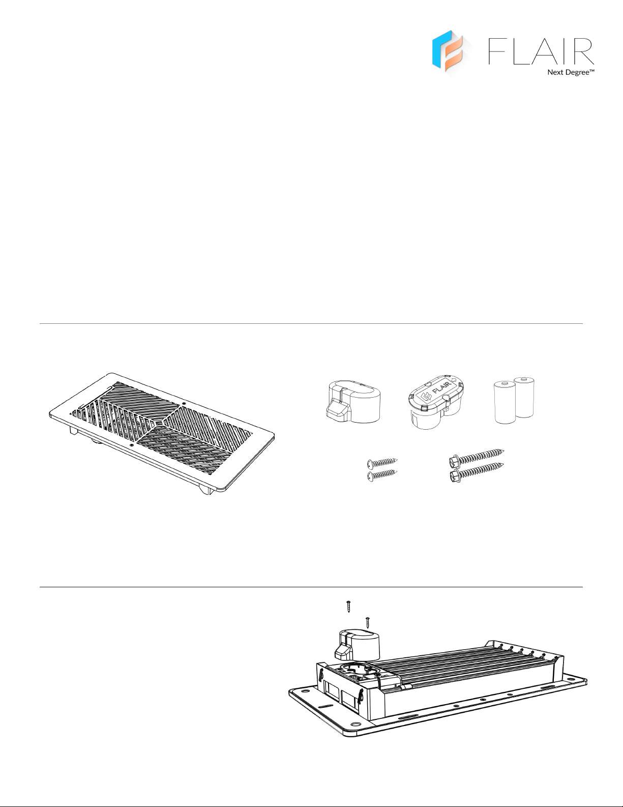
A. Smart Vent
C. 2 C Cell Batteries
E. Top Battery Holder
B. 2 Mounting Screws
D. Bottom Battery Holder
F. Battery Holder Screws
AssemblyandInstallation
1. Attach Bottom Battery Holder
Insert the Bottom Battery Holder into the back of the vent. Screw
in the two Battery Holder Screws. Ensure the screws are fully
inserted and snug but do not over tighten as you might strip the
plastic.
Over →
1
Page 2
2. Insert Batteries
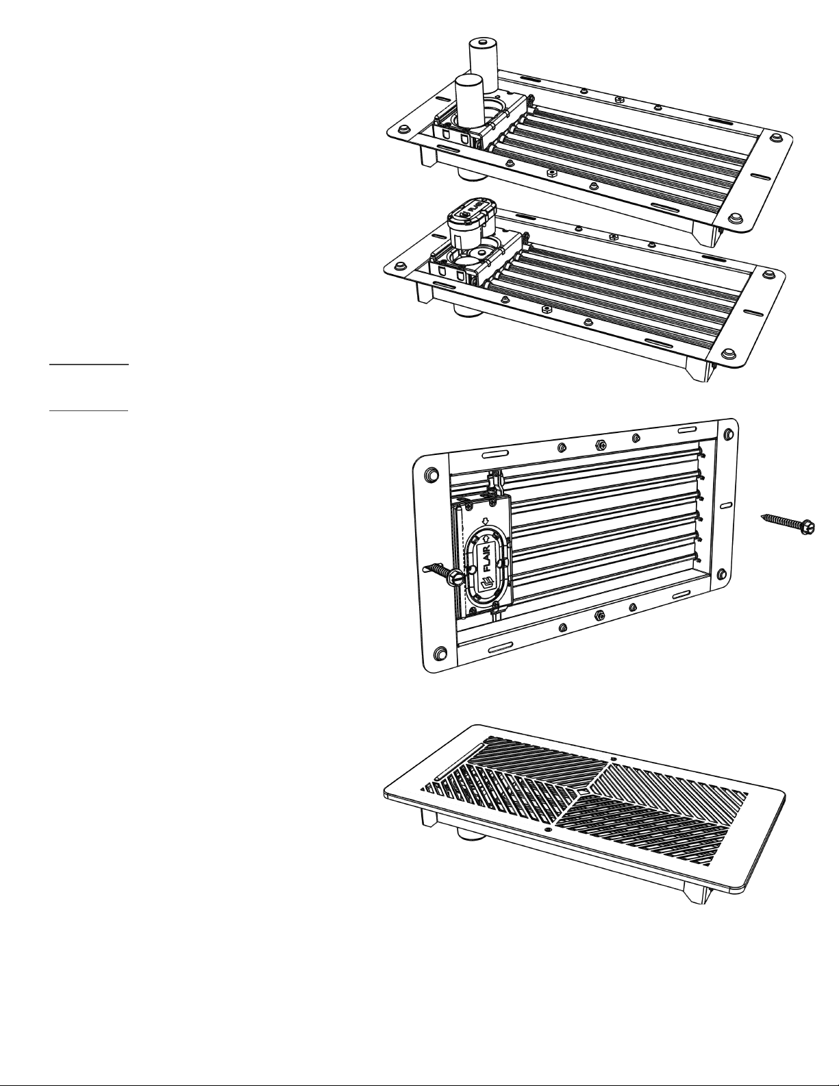
Remove faceplate if attached. Note the battery orientation and
insert the two batteries.
If you plan to wire in your vents, DO NOT insert batteries. For
further instructions on
the wired installation, see the wired installation instructions.
3. Attach Top Battery Holder
Align the arrow on the Top Battery Holder with the arrow on the
main vent body.
Push the Top Battery Holder down over the batteries and screw in
both both screws. These screws are attached to the Top Battery
Holder already unlike the ones from step 1. Upon insertion, you
should see the lights turn on briefly.
4. Mount or Insert
Floor installation
Place the vent into the duct opening on the floor.
Wall and Ceiling
Insert the vent into the wall or ceiling. Using the supplied mounting
screws, insert the screws into the mounting holes on the two ends of the
vent. Closest to the middle of the vent is the best location in the slot but
you may need to insert the screws farther from the center of the vent to
align with existing holes.
In most cases, your existing holes should work great. If however the
mounting holes are stripped or loose, you have options. You can add
drywall anchors to the existing holes or you can use the alternative
mounting holes on the sides of the vent. If you opt for using the side
mounting holes, we recommend using drywall anchors (not included)
and using 4 screws (not included).
Be sure that the vent is securely fixed to the wall or ceiling. If unsure,
contact a handyman or contracting service. Flair is not liable or
responsible for damage or injury resulting from vents falling from the
wall or ceiling.
5. Attach Faceplate
Attach the faceplate with the two screws and you are all finished.
Install any other vents and move over to the digital setup via the
Flair App or my.flair.co.
6. Digital Installation
For initial setup of your Flair System, be sure to refer to the Puck
Installation Guide. Once you are ready to associate the vent with
a room, the light bar should show a unique code. If you don’t
see any lights on your vent’s light bar or if you are adding
this vent to an already configured system, go to Home
Settings → Flair Devices and enable Setup Mode.
2
Page 3
WiredInstallation
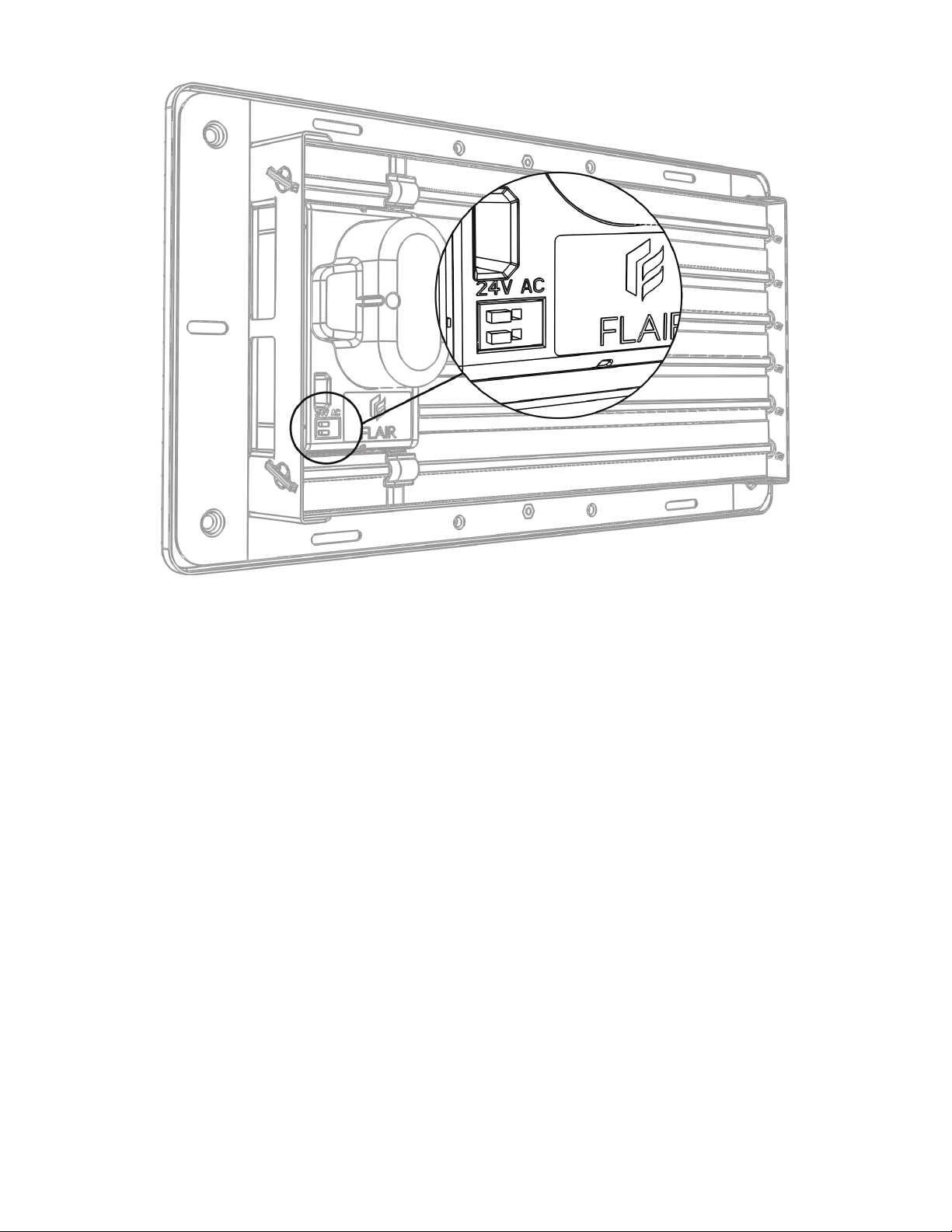
24V AC Optional Power Port
Use with: 20AWG Plenum Rated Solid 2 Conductor Wire
@24VAC: less than 1mA continuous, max 50mA Intermittent
1. Follow Instructions from Assembly and Installation but DO NOT insert batteries.
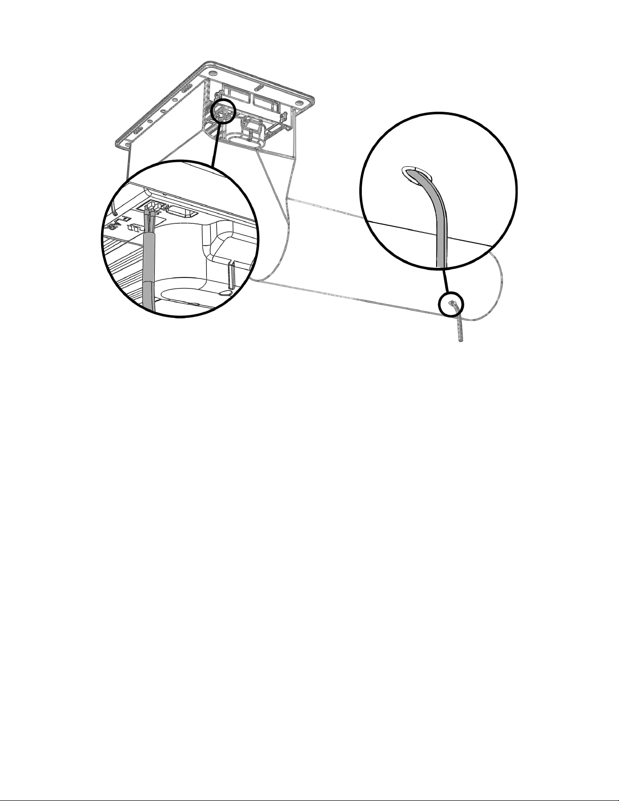
2. Drill a hole in the boot or duct near the vent, wherever convenient. The hole size should be large enough for 20AWG Plenum
Rated Solid (2 Conductor) wire.
3. Slide 20AWG Plenum Rated Solid (2 Conductor) wire through the hole into the boot or duct.
4. Pull enough wire through to reach the back of the vent (boot dependent) - if you pull some extra, you can trim it later. When
pulling the wire through, be careful to avoid stripping the wire on the metal boot or duct as this could lead to a short.
5. With the wire in place,use high quality Duct Tape or Mastic to seal the hole in the boot or duct.
6. Strip insulation, press the terminal block buttons, and insert each conductor into the 24VAC port on the back side of Vent
(either wire can go in either hole, polarity does not matter).
7. If there is excessive wire in the boot or duct, trim the wire repeat step 5. Ensure that the wire doesn’t interfere with the Vent’s
louvre movement. Also ensure the two wires are fully separated and cannot short near the vent terminal block. In case of
excess exposed wire at the vent terminal block, press the release buttons on the terminal block and pull the wires out. Trim
exposed wire as needed and reinsert.
8. Connect the other end of wire to a 24VAC transformer/power supply (note that you will not need to wire to the ground
pin/terminal if one is available).
9. Continue with regular installation.
10. Plug in or power 24VAC power supply/transformer.
11. You can now continue with the Digital Installation.
Electrical Notes:
● Flair Vents operate with very low power requirements and operate at different times hence a 40VAC (@24V) will suffice for in
excess of 10 vents. Beyond 10 Vents, it is recommended that you consider additional power supplies due to the length of the
wire runs becoming very long.
● Grounding is not needed.
3
Page 4
FCC STATEMENT
Changes or modifications not expressly approved by the party responsible for compliance could void the user’s authority to operate the equipment.
This equipment has been tested and found to comply with the limits for a Class B digital device, pursuant to Part 15 of the FCC Rules. These limits are
designed to provide reasonable protection against harmful interference in a residential installation. This equipment generates, uses and can radiate radio
frequency energy and, if not installed and used in accordance with the instructions, may cause harmful interference to radio communications. However,
there is no guarantee that interference will not occur in a particular installation.
If this equipment does cause harmful interference to radio or television reception, which can be determined by turning the equipment off and on, the user
is encouraged to try to correct the interference by one or more of the following measures:
-- Reorient or relocate the receiving antenna.
-- Increase the separation between the equipment and receiver.
-- Connect the equipment into an outlet on a circuit different from that to which the receiver is connected.
-- Consult the dealer or an experienced radio/TV technician for help.
This equipment complies with FCC radiation exposure limits set forth for an uncontrolled environment. This equipment should be installed and operated
with minimum distance 20cm between the radiator and your body. This transmitter must not be co-located or operating in conjunction with any other
antenna or transmitter.
Canada Statement
This device complies with Industry Canada license-exempt RSS standard(s). Operation is subject to the following two conditions: (1) this device may not
cause interference, and (2) this device must accept any interference, including interference that may cause undesired operation of the device.
Le présent appareil est conforme aux CNR d'Industrie Canada applicables aux appareils radio
exempts de licence. L'exploitation est autorisée aux deux conditions suivantes : (1) l'appareil ne
doit pas produire de brouillage, et (2) l'utilisateur de l'appareil doit accepter tout brouillage
radioélectrique subi, même si le brouillage est susceptible d'en compromettre le fonctionnement.
This equipment complies with FCC/IC RSS-102 radiation exposure limits set forth for an uncontrolled environment. This equipment should be installed
and operated with minimum distance 20cm between the radiator & your body.
Ce matériel est conforme aux limites de dose d'exposition aux rayonnements, fac / ic rss-102 énoncée dans un autre environnement.cette equipment
devrait être installé et exploité avec distance minimale de 20 entre le radiateur et votre corps.
4
 Loading...