

Standa 8SMC5-USB User Manual

Download user manual in pdf
For quick simple questions you can contact us via Telegram.
The official technical support channel @SMC5TechSupport ( https://t.me/SMC5TechSupport).
Available online Mon-Fri 8:00-16:00 UTC.
8SMC5-USB User Manual
1. About
1. General information
2. Benefits
3. Table of specifications
4. Specifications
2. Safety instructions
3. Overview and getting started
1. One axis configuration
2. Example of a motor connection
3. Manual profile setting
4. Calculation of the nominal current
5. Possible problems and solutions
4. Technical specification
1. Appearance and connectors
1. Controller board
2. One axis system
3. Two axis system
2. Kinematics and rotation modes
1. Predefined speed rotation mode
2. Rotation for predefined point
3. Predefined displacement mode
4. Acceleration mode
5. Backlash compensation
6. Rotation reversal
7. Recommendations for accurate rotation
8. PID-algorithm for DC engine control
9. Stop motion modes
10. PID-algorithm for BLDC engine control
3. Main features
1. Supported motor types
2. Motor limiters
3. Limit switches
4. Automatic Home position calibration
5. Operation with encoders
6. Revolution sensor
7. Steps loss detection
8. Power control
9. Critical parameters
10. Saving the parameters in the controller flash memory
11. User defined position units
4. Safe operation
5. Additional features
1. Operating modes indication
2. Operations with magnetic brake
3. Joystick control
4. Left-Right buttons control
5. TTL synchronization
6. Design of multi-axis system
7. General purpose digital input-output
8. General purpose analog input
9. External driver control interface
10. Serial port
11. Saving the position in controller's FRAM memory
12. The Standa stages detection
6. Secondary features
1. Zero position adjustment
2. User-defined position adjustment
3. Controller status
4. USB connection autorecovery
5. XILab application User's guide
1. About XILab
2. Main windows of the XILab application
1. XILab Start window
2. XILab Main window in single-axis control mode
3. XILab Main window in multi-axis control mode
4. Application Settings
5. Charts
6. Scripts
Page 1 / 345
Page 1 / 345

7. XiLab Log
3. Controller Settings
1. Settings of kinematics (Stepper motor)
2. Motion range and limit switches
3. Critical board ratings
4. Power consumption settings
5. Home position settings
6. Synchronization settings
7. Brake settings
8. Position control
9. Settings of external control devices
10. UART settings
11. General purpose input-output settings
12. Motor type settings
13. Settings of kinematics (DC motor)
14. Settings of PID control loops
15. About controller
16. Settings of kinematics (BLDC motor)
4. XILab application settings
1. XILab general settings
2. General motor settings
3. Attenuator settings
4. Cyclical motion settings
5. Log settings
6. Charts general settings
7. Charts customization
8. User units settings
9. About the application
5. Positioner specifications
1. Positioner name
2. Positioner general characteristics
3. Motor characteristics
4. Encoder specifications
5. Hall sensor characteristics
6. Reducing gear specifications
7. Accessories specifications
6. Correct shutdown
7. Working over network
8. XILab installation
1. Installation on Windows
1. Installation on Windows XP
2. Installation on Windows 7
3. Installation on Windows 8
2. Installation on Linux
3. Installation on MacOS
6. Programming
1. Programming guide
1. Working with controller in Labview
2. Working with controller in Matlab
2. Communication protocol specification
3. 8SMC1-USBhF software compatibility
4. Libximc library timeouts
5. XILab scripts
7. Files
1. Configuration files
1. Translation Stages
1. 8MT160 - Motorized Delay Line
2. 8MT295 - Long-Travel Motorized Linear Stages
3. 8MT195 - Long-Travel Motorized Linear Stages
4. 8MT167 - Motorized Translation Stage
5. 8MT173 - Motorized Translation Stages
6. 8MT173DC - Motorized Translation Stages
7. 8MT50 - Motorized Translation Stages
8. 8MT30 - Narrow Motorized Translation Stages
9. 8MT175 - Motorized Translation Stages
10. 8MT177 - Motorized Translation Stage
11. 8MT184 - Motorized Translation Stage
12. 8MT193 - Motorized Translation Stage
13. 8MT200 - Motorized Translation Stages
14. 8MTF - Motorized XY Scanning Stage
15. 8MTF2 - Motorized Fiber Coupling Stage
16. 8MTFV - Motorized Translation Stage
17. 8MT60 - Motorized Translation Stage
2. Rotation Stages
1. 8MR151 - Motorized Rotation Stages
2. 8MR170 - Motorized Rotation Stages
Page 2 / 345
Page 2 / 345

3. 8MR174 - Motorized Rotation Stage
4. 8MR190 - Motorized Rotation Stage
5. 8MR191 - Motorized Rotation Stage
6. 8MRB250 - Large Motorized Rotation Stage
7. 8MRU - Universal Motorized Rotation Stages
8. 8MPR16-1 - Motorized Polarizer Rotator
9. 8MRH240 - Large High Capacity Rotary Stage
3. Vertical Translation Stages
1. 8MVT100 - Vertical Translation Stage
2. 8MVT120 - Vertical Translation Stage
3. 8MVT188 - Vertical Translation Stage
4. 8MVT40 - Vertical Translation Stage
5. 8MVT70 - Vertical Translation Stage
4. Screws and actuators
1. 8MS00 - Motorized Screws
2. 8CMA06 - Motorized Actuator
3. 8CMA20 - Compact Motorized Actuator
4. 8CMA28 - Motorized Linear Actuator
5. 8CMA16DC - Motorized Linear Actuator
5. Motorized Goniometers
1. 8MG00 - Motorized Goniometers
2. 8MG99 - Motorized Goniometer
6. Mirror Mounts
1. 8MTOM2 - Motorized Two Axis Translation Optical Mount
2. 8MUP21 - Motorized Optical Mount
3. 8MBM24 - Motorized Mirror Mounts
4. 8MMA60 - Motorized Mirror Mounts
5. 8MBM57 - Large Aperture Motorized Mirror Mount
6. 8MKVDOM - Motorized Vertical drive optical mount
7. Motorized Attenuators
1. 10MCWA168 - Motorised Closed Variable Wheel Attenuator
2. 10MWA168 - Motorized Variable Wheel Attenuator
8. Motorized Iris Diaphragms
1. 8MID98 - Motorized Iris Diaphragm
2. Software
8. Related products
1. Ethernet adapter
1. Overview
2. Administration
Page 3 / 345
Page 3 / 345

1. About
1. General information
2. Benefits
3. Table of specifications
4. Specifications
Page 4 / 345
Page 4 / 345
1.1. General information
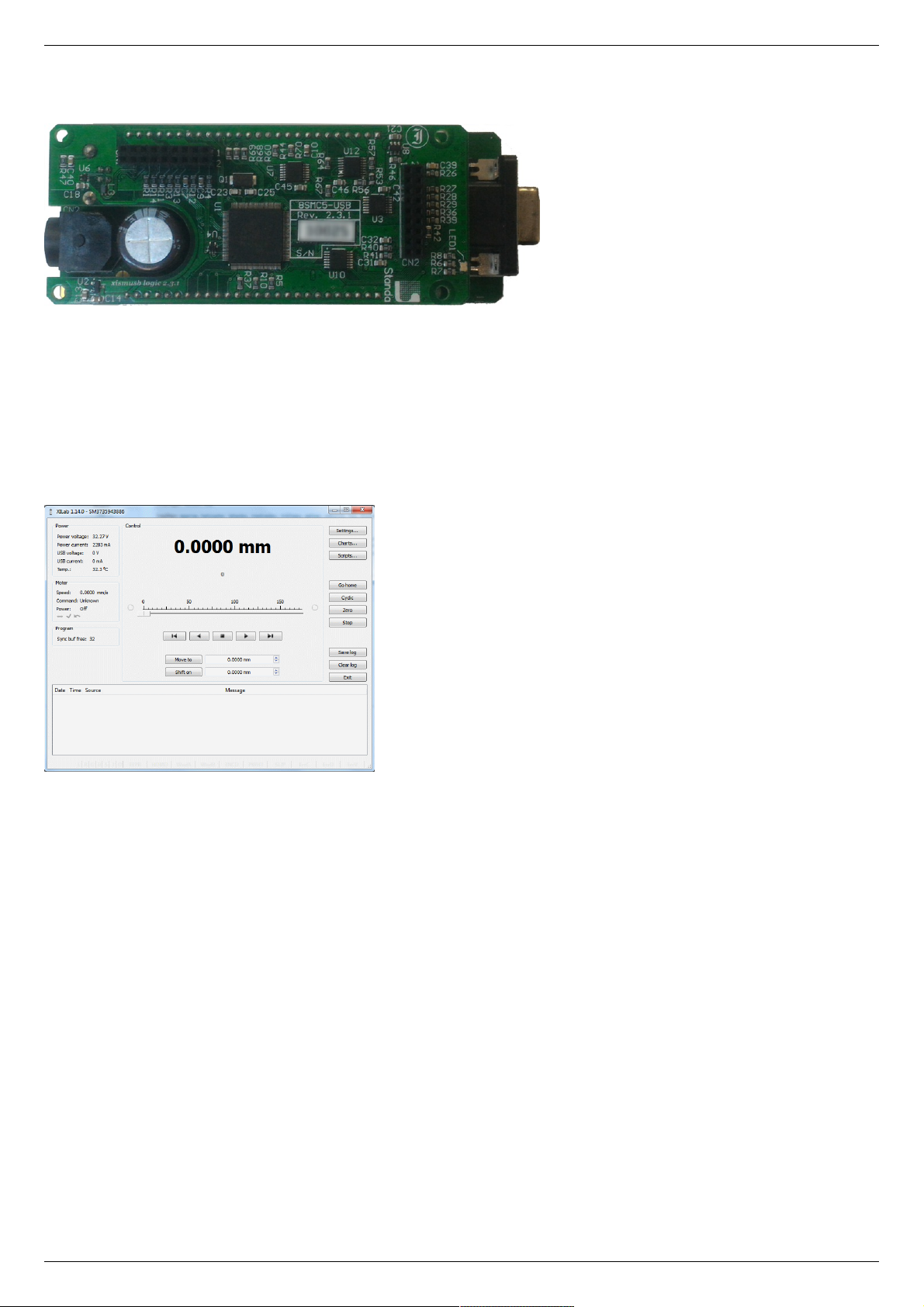
Controller board.
We offer an inexpensive and ultra-compact servo-drive with USB interface for stepper motors with external power supply.
Forget about cumbersome and expensive servo-drives! All you need is a stepper motor, a controller, a USB cable and any stabilized
external power supply. That is all! Forget about active coolers as well. Controller's board is about the same size as a notepad or a
cellphone, therefore, you may just put it down on the worktable without any assembly procedures. The controller works with any type
of compact stepper motors with the rated winding current of up to 3A. Controller works with stepper motors with no feedback as well
as with ones equipped with encoders in feedback loop, including linear encoders on the stages. The motor connector on the controller
board is the same as one used by Standa company and it fits to all the Standa stages. USB connector provides easy communication
and work with computer. Several controllers can be connected to one computer either via USB ports or through a special backplane
supplied with multiaxis systems. The controller is fully compatible with the majority of operating systems, e.g., Windows, Mac OS X,
Linux, etc.
XILab main window.
All the necessary software including all configuration files are supplied with the controller. It allows you to start working with it the
controller right out of the box, according to "plug-and-play" principle. We continuously develop additional configuration files for newly
supported motors. Therefore, all you need is to download the file for your stage from Configuration files chapter, open it with XILab
software and hit Apply. Your controller is now fully configured! Just issue movement commands and controller will do whatever you
want.
Page 5 / 345
Page 5 / 345

1.2. Benefits
Main benefits
Compact and powerful! The controller's dimensions are 47x25x125 mm including all connectors. The device is adapted to all
stepper motors with rated winding current of up to 3A.
Compatible with 8SMC1-USBh After updating the MicroSMC driver, all the software for 8SMC1-USBh will be working with
8SMC5-USB.
Compatible with all the Standa stages! Have you got a Standa stage? Just plug and play, we have already done the rest for
you!
It does remember all! Do not worry about saving the current position on the computer: the controller does it itself using its
own nonvolatile memory that works even after a sudden power cut.
It works with peripherals! It supports a quadrature encoder, magnetic brake, a joystick, limit switches, a zero position sensor
– all included, just plug and work!
Built-in zero calibration! Using the limit switches, the revolution sensor, the external signal or their combination, the zero
calibration is performed by a single command!
It works with all computers! All the supplied software is compatible with Windows 8, Windows 7, Windows Vista, Windows XP
SP3, Linux, Mac OS X, including 64-bit versions.
All benefits
Really powerful! It is adapted to all the stepper motors with rated winding current of up to 3A.
Compatible with 8SMC1-USBh After updating the MicroSMC driver, all the software for 8SMC1-USBh will be working with
8SMC5-USB.
Compatible with all the Standa stages! Have you got a Standa stage? Just plug and play, we have already done the rest for
you!
It knows its own set! A built-in feature for downloading the configuration file right from the stage memory is available! The
stage's support of such memory is required.
Choose your interface! Both USB and serial port are built-in and ready to use.
Really fast! Up to 35,000 steps per second for any microstep mode!
Precise! The microstep modes from full step to 1/256 of the step on all the speeds.
It does remember all! Do not worry about saving the current position on the computer: the controller does it itself using its
own nonvolatile memory that works even after a sudden power cut.
It works with peripherals! It supports a quadrature encoder, magnetic brake, a joystick, limit switches, a zero position sensor
– all included, just plug and work! Additional stabilized output for peripherals (5V, 100mA) is available.
Built-in zero calibration! Using the limit switches, the revolution sensor, the external signal or their combination, the zero
calibration is performed by a single command!
Stand-alone! Would you like to work in the stand-alone mode? Just go ahead! An external joystick, a keypad or their
combination is supported.
Energy conserving! Programmable current reduction in the motor windings in the hold mode with 1% accuracy.
Silent! Smooth movement at lower speeds and no extra noise at higher speeds.
Protected! An ESD protection on all pins of external connectors and additional short circuit protection for the motor windings.
Attentive! It controls the temperature of the processor and the power driver as well as both currents and voltages for the power
supply and USB.
Modern! The firmware in the nonvolatile memory of the controller can be updated via USB interface.
Controlling and controllable! The built-in synch input and output allow to start the rotation to desired position by the
incoming external signal and/or to transmit the outgoing signal after the desired position is reached. The analog common input
and the digital common input/output are built in as well.
Comprehensible! The status LED displays the power supply and the controller's state. For convenience of use both signals
doubled at the external LEDs as well as the state of the limit switches.
Multiaxis machine! The multiaxis systems are designed by using standard USB hubs, either external or mounted at a special
backplane. There may be up to 32 axis in the system.
It works with all computers! All the supplied software is compatible with Windows 8, Windows 7, Windows Vista, Windows XP
SP3, Linux, Mac OS X, including 64-bit versions.
Examples for all programming languages! Controllers are supplied with cross-platform library and examples which allow
rapid development using C++, C#, .NET, Delphi, Visual Basic, gcc, Xcode, Matlab, Java and LabVIEW.
Full-featured interface! The XILab user interface is supplied with the controller. It allows to easily control all the functions and
features of the device without any programming.
Unique scripting language! A scripting language is integrated into XILab software. It allows easy setting the sequence of
actions, including cycles and branches, without compilation or learning any programming language.
New! Stepper motor close-loop control algorithm are ready! Motion is smoother and faster than ever with innovation
encoder based close-loop on all 8SMC5-USB motor controllers. It combines advantages of BLDC motor control with cheapness of
conventional stepper motors. No hidden catch, no stall or hitch, just free move!
Page 6 / 345
Page 6 / 345

1.3. Table of specifications
Power supply external 12V - 48V DC
Current
consumption
up to 5A (depending on the voltage) from external power supply
Current in the
motor winding
up to 3A
Protection types current overload protection, voltage overload protection, short circuit protection, motor hotplug/unplug protection
Motion modes
move left/right, move to point, shift on delta, continuous speed, acceleration and deceleration ramps, backlash
compensation mode, automatic home position calibration mode
Step modes full-step, 1/2, 1/4, 1/8, 1/16, 1/32, 1/64, 1/128, 1/256
Rotation speed up to 35 000 full steps per second
Speed profile trapezoidal
Position counter 40 bit
Feedback Single-ended and differential quadrature encoder (optional)
Limit switches 2
Feedback
bandwidth
200 kHz for single-ended and 5MHz for differential encoder
Note: The controller's working voltage range is 12V to 48V DC. The voltage limits are 12V and 50V DC. If the voltage
exceeds 50V, the controller is guaranteed to fail. If the voltage falls below 12V, the controller turns off.
Page 7 / 345
Page 7 / 345

1.4. Specifications
Motor requirements
Motor type: bipolar stepper motor, DC motor.
Rated winding current: minimum 100mA.
Rated winding voltage: minimum 2V DC.
Electric specifications of the controller
Power supply modes: external.
Current in each motor winding: up to 3A.
Maximum encoder pulse frequency: 200 kHz for single-ended and 5MHz for differential encoder.
Stabilized 5V DC output (the power supply for encoder and other peripherals): 100mA maximum output current, 5% or better
output voltage stability.
ESD-protection on all pins of the output connectors (e.g., D-Sub 15 pin, mini-USB or power jack).
Winding-to-ground short circuit protection.
Winding-to-winding short circuit protection.
Motor hot-swapping protection.
Wrong power polarity protection (no more than 1s).
Voltage overload protection (no more than 1s).
USB-supplied current limitation.
External power supply current limitation.
Motor rotation speed limitation.
Programmable full winding current with 10mA precision.
Programmable winding current decrease with 1% precision for the hold mode.
Rotation control features
Microstep modes: full-step, 1/2, 1/4, 1/8, 1/16, 1/32, 1/64, 1/128, 1/256.
Noiseless at low speeds.
Minimum speed is 1/256 of the full step per second.
Maximum speed is up to 35 000 full steps per second for all microstep modes.
Minimum shift is 1/256 of the step.
Maximum shift is 2,147,483,647 full steps for all microstep modes.
Smooth start/stop mode.
40-bit position counter (32 bits for full step and 8 bits for microstep).
Motion modes: left/right move, move to point, shift on delta, continuous speed, acceleration and deceleration ramps, backlash
compensation mode, automatic home position calibration mode.
Additional firmware features
Automatic HOME calibration at firmware level.
The nonvolatile memory used for saving/downloading the controller settings.
Software update via USB interface.
Automatic position saving according to step counter and encoder with power-off protection.
Additional features available via motor connector
Processing the signals from one or two limit switches; software configurable.
The Standa stages recognition and automatic downloading of the configuration file right from the stage if the last one supports
this feature.
The "step loss" detection and position recovery using either a revolution sensor or a quadrature encoder (if the stage supports
this feature).
The position detection using a quadrature encoder. The x4 mode.
The stepper motor control using master quadrature encoder mode, providing the maximum speed without any step loss. Starting
with firmware 4.1.
Additional features available via backplane connector
USB connector on backplane that duplicates USB input on controller board.
A serial RS-232 port. TX and RX lines are available. Specifications: 9600 - 921600 baud speed, TTL 3.3V. The Ethernet,
Bluetooth, WiFi, ZigBee and other configurations based on the serial port are available by request.
Synchronization input: once the pulse is received via this pin, the controller starts rotating the motor to predetermined position
or by predetermined shift value. The triggering mode, the polarity and duration of the pulse are adjustable by user.
Specifications: TTL 3.3V.
Synchronization output: emit pulse to this pin if rotation is started or finished, or predetermined user-defined shift value is
reached. The triggering mode, the polarity and duration of the pulse are adjustable by user. Specifications: TTL 3.3V.
Left or right buttons. Once the button is pressed, the rotation in corresponding direction starts and the speed increases gradually
according to acceleration and other settings. Specifications: TTL 3.3V.
Joystick pin allowing operation with various joysticks with the voltage range no more than 0–3V.
Magnetic brake control pin providing control to magnetic brake mounted on the motor shaft. Specifications: TTL 3.3V, 5mA.
Common analog input pin allowing operation with signals within 0–3V range. Reading frequency is 1kHz. The configuration is
programmable.
Common digital input/output pin. 1kHz update frequency, software configurable. Specifications: TTL 3.3V, 5mA.
Page 8 / 345
Page 8 / 345

Limit switches indication pins designed for LED direct connection. Specifications: TTL 3.3V, 2mA.
Digital "Power" and "Status" pins duplicate the status LED and designed for direct connection of LEDs. Specifications: TTL 3.3V,
2mA.
External driver control interface allowing to control any type of external driver using three signals: enable, direction, clock.
Multiaxis systems development. The multiaxis systems are created from standard USB hubs, either external or mounted at a
special backplane. On the PC a multiaxis system is represented as a set of virtual serial ports, according to the number of
connected axes.
Programming the controller
All the software supplied with controller is compatible with Windows 8, Windows 7, Windows Vista, Windows XP SP3, Linux, Mac
OS X, including 64-bit versions.
Controllers are supplied with cross-platform library and examples which allow rapid development using C++, C#, .NET, Delphi,
Visual Basic, gcc, Xcode, Matlab, Java and LabVIEW.
The XILab user interface is supplied with the controller. It allows to easily control all the functions and features of the device
without any programming.
A scripting language, an EcmaScript language dialect, is integrated into XILab software. It allows easy setting the sequence of
actions, including cycles and branches, without compilation or learning any programming language.
Page 9 / 345
Page 9 / 345

2. Safety instructions
Power supply and grounding requirements. Connection to controller
General requirements for a controller board, systems in box ( single and double axes) are listed below.
IMPORTANT. Either the power supply unit should be plugged to grounded 220V AC socket (a three-wire connection
scheme). Make sure that the minus electrode of your power supply unit is grounded. If the power supply unit with
minus electrode disconnected from the grounding circuit is used, ground the controller board via special grounding
terminal (look at the picture below). Non-compliance with these rules may lead to the decrease in controller stability
and noise resistance.
Top view of the controller board. A grounding terminal marked with the red square
Typical connection diagram for a controller (board, systems in box):
Controller
8SMC5-USB
PC
Power
supply
Motor
USB
220 V
Controller grounded via minus electrode of power cable connection diagram
Controller
8SMC5-USB
PC
Power
supply
Motor
USB
220 V
Controller connection diagram with grounding via special terminal
Page 10 / 345
Page 10 / 345
Warning. Power supply unit should be able to supply sufficient current to rotate the motor. As an absolute minimum
it should be able to supply where is the minimum working current of
power supply unit, is the operating current in the winding, is power supply unit stabilized voltage, and
is rated operating voltage of the motor. It is recommended to use a power supply unit with operating current
equal to . The voltage should be greater than . The higher the voltage, the
faster rotation speed could be reached.
One can use power consumption of power supply unit to calculate minimum requirements instead. An absolute
minimum of power is . For example, for motor with
operating winding current of 1A and operating voltage of 5V (with 5W rated power consumption), the operating
voltage of power supply unit may be chosen at 20V with the output power of at least 10W (the maximum operating
current of power supply unit is at least 0.5A).
Controller board
IMPORTANT. It is strictly forbidden to touch the controller board without any antistatic equipment. We recommend
you to use antistatic wrist strap.
IMPORTANT. It is strictly forbidden to connect positive wire of power supply to the controller board when
ground wire is not connected. It is strictly forbidden to connect or disconnect power cable when the
power supply is on, the controller is connected to the PC and the power supply and the PC are grounded.
This may damage the PC! This is a common requirement for any electronic device with separate power source,
which is connected to the PC via USB.
Warning. Before connecting the controller board to the motor or to the PC via USB interface, it is recommended to
connect controller to power supply with proper grounding or to use separate grounding for controller with the specially
marked ground terminal (look above).
One and two axes system in box
IMPORTANT. You should not exceed maximum allowed voltage of 48V. If voltage goes over allowed value at
more than 2 volts, it can immediately and irreversibly damage the controller.
Page 11 / 345
Page 11 / 345

3. Overview and getting started
This guide describes the operation of controller for multi-axis and one-axis systems, basic parameters configuration and getting started
with XILab software for Windows 7.
One axis configuration - a brief description of the beginning of work with the controller + 8SMC5-USB for one axis +. It is also
considered quick XiLab setup and lists all necessary equipment.
Example of a motor connection - connection of stepper motor Nanotec ST5918L3008-B with encoder CUI INC AMT112S-V to
8SMC5-USB controller. It is described how to make your own cable, guided by the specification on the engine and explanation of
the specification is given.
Manual profile setting - setting of working profile for XiLab. Overview of the main features.
Calculation of the nominal current - setting of amplitude of nominal current for stepper motors.
Possible problems and solutions - description and solution of the most common problems when working with 8SMC5-USB
controller.
Page 12 / 345
Page 12 / 345

3.1. One axis configuration
Introduction
System requirements
Software installation and startup procedures
Getting started with XILab software
Functional test
Control from user applications
3.1. One axis configuration
Controller board.
Introduction
This manual describes the controller installation procedures and getting started with XILab software for Windows 7. The detailed
controller specifications are described in Specifications chapter. For developing your own applications, please read the Programming
guide 8SMC5 chapter and download the programming software package from the software chapter.
System requirements
Note. There are only brief requirements in this chapter. For detailed information please read the Specifications
chapter.
For successful installation you will need:
PC with USB port
A standard PC with USB port.
Make sure that your PC has all of the current Windows updates installed. It will help you to maintain software compatibility. If
necessary, please download the latest updates from www.microsoft.com/updates.
Software
All necessary software to work with the controller can be downloaded from software page.
USB A - mini-B cable
USB-A to mini-USB-B cable.
For detailed information about the USB cable please read the data connector chapter.
8SMC5-USB controller
Page 13 / 345
Page 13 / 345

The motor controller board.
The controller appearance may differ from the one shown on the above figure depending on its configuration and version. For
detailed information about versions please read the Appearance and connectors 8SMC5 chapter.
Positioner or motor
The stepper motor-based positioner.
The stepper motor-based positioner used in the operations is shown at the figure. The detailed motor requirements are described
in Specifications chapter. If you use your own cables for connecting the positioner to the controller, please refer to positioner
connection scheme and the controller's output connector scheme . For positioners with limited movement range, two limit
switches must be used: SW1 and SW2. These pins are used to determine the movement limits.
Power supply
Stabilized power supply unit.
Notes.
Please use the 12–36V DC stabilized power supply. Too high voltage may damage the controller. For more
information please read the Safety instructions 8SMC5 chapter. The power supply unit must provide the current
enough for sustainable rotation of the motor.
Please pay attention on the manual supplied with your controller. The more strict power voltage limitation is
possible depending on the controller model. Please check the connection of external power supply unit to the
controller carefully.
If controller is supplied inside the metal case, the case must be grounded. If controller is supplied without any
body, the grounding circuit of power supply unit is used. For more information please read the Safety
instructions 8SMC5 chapter.
If the board is operated without the casing, make sure it lays on the insulating surface and there are no
extraneous particles on the board or around it.
Software installation and startup procedures
Make sure that all controllers are disconnected from your PC.
The software installation manual is here. The installer file name is "xilab-<version_name>.exe". It automatically detects whether it is
running on 32-bit or 64-bit version of Windows and installs the appropriate version of XiLab. Launch the installation program, the
installation window will appear. (The software versions may slightly differ from each other).
Page 14 / 345
Page 14 / 345

XILab main installation window.
Press “Next>” button and follow the instructions on screen. All the necessary software including all drivers, packages and programs will
be installed automatically. After installation is finished, the XiLab software starts by default and the following window will open:
XILab "No devices found" dialogue window.
Don't press any buttons.
Connect the positioner to the controller. Connect the stabilized power supply unit to the controller. Ground the controller or power
supply unit. Connect the controller to your PC using the USB-A to mini-USB-B cable.
The LED indicator at the controller board will start flashing. The New Hardware Wizard starts working after the first connection of the
controller to PC. Please wait until Windows detects a new device and installs all necessary drivers for it.
If the automatic driver installation has failed, please select ”No, not this time” in the window being opened and press “Next>” button.
Select “Install from a list or specific location (Advanced)” in the next window and press “Next>” again. Browse the software disk
supplied with controller and find the *.inf file there or in the XiLab-install-path\driver\ folder and wait until installation is completed.
Go back to XILab "No devices found" dialog window and press "Retry" button.
If this window was closed, please go to “Start” menu, select Programs->XILab Х.Х.Х->XILab and launch it. The dialog window will
open again.
Getting started with XILab software
XILab is a user-friendly graphic interface designed for control, diagnostics and adjustment of motors. It can also be used for easy
installation and save/restore of parameters for any type of motors. This chapter describes the startup procedures with XILab software.
For complete information please refer to XILab application User's guide chapter.
Page 15 / 345
Page 15 / 345
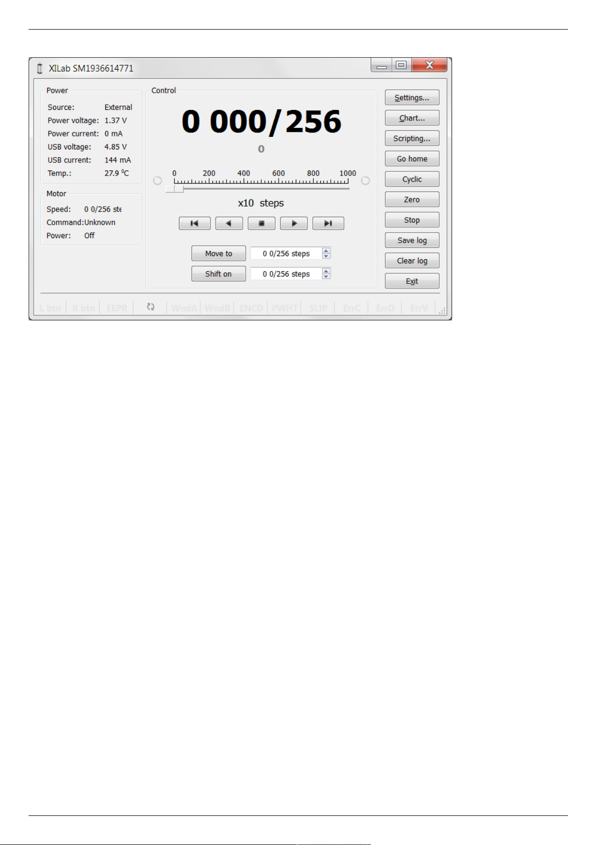
XILab main window.
Open “Settings...”, then press “Restore from file...” and select the configuration file for your positioner from the opened C:\Program
Files\XILab\profiles\ folder. The values applicable for your positioner will automatically fill all the fields of “Settings...” menu. If the
necessary file isn't found, please refer to the Configuration files chapter. If there is still no solution, please leave your request at our
customer service website.
Page 16 / 345
Page 16 / 345
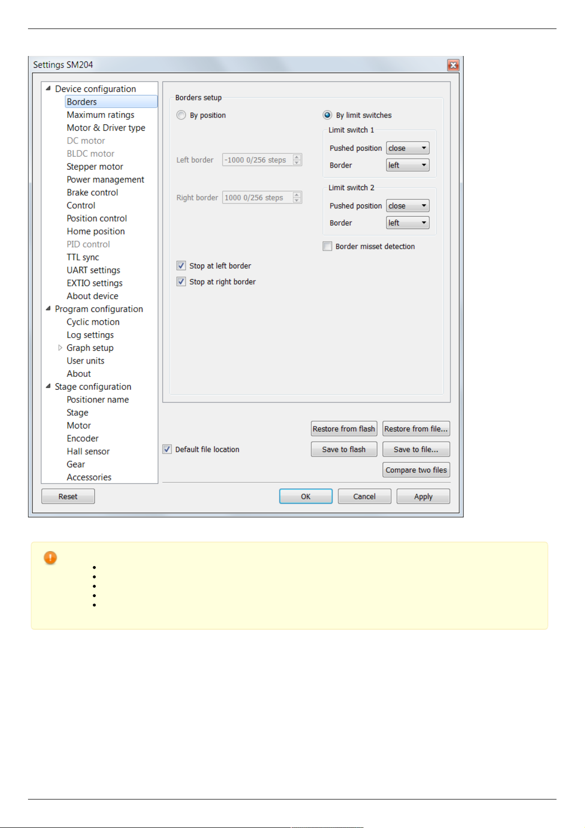
XILab, the Settings menu window.
Warning. For the controller to work with stepper motors it is required to properly set up:
working current,
displacement limits and limit switches ,
critical parameters ,
limiters,
power supply mode.
If you decide to configure your controller by yourself, please check these parameters carefully!
Congratulations, your controller is ready for operation!
Functional test
Check if the controller is configured properly by pressing left or right button in the central row of XILab main window control buttons.
The positioner has to start moving. Use the central "soft stop" button to stop the rotation. Please pay attention to the power supply
parameters of the controller in the Power section. The power voltage, working current and temperature of the controller can be set
there.
If Xilab main window is shaded red when the movement was supposed to start, that means that protection was activated and controller
entered the Alarm state. This may be caused by incorrect settings, wrong connection of the positioner or controller malfunction. For
detailed information please read the Critical parameters chapter.
Page 17 / 345
Page 17 / 345

Control from user applications
Xilab software is a convenient way to control stages connected to 8SMC5-USB controller. However, if you need to control the 8SMC5USB from your own application, you may do so by using libximc library. Programming guide 8SMC5 has several examples in C, C#,
Delphi, Java, VB.net, Matlab, LabView programming languages. If all you need is to automate a small number of control steps, then
instead of a standalone program you may find it easier to use Xilab scripting language .
Page 18 / 345
Page 18 / 345
3.2. Example of a motor connection
General case
Positioner standard connection diagrams
Example
Preparation
Connecting the motor and encoder to the
controller
3.2. Example of a motor connection
General case
To connect a motor to the controller please refer to positioner connector, and
use the scheme of positioner connection:
Positioner standard connection diagrams
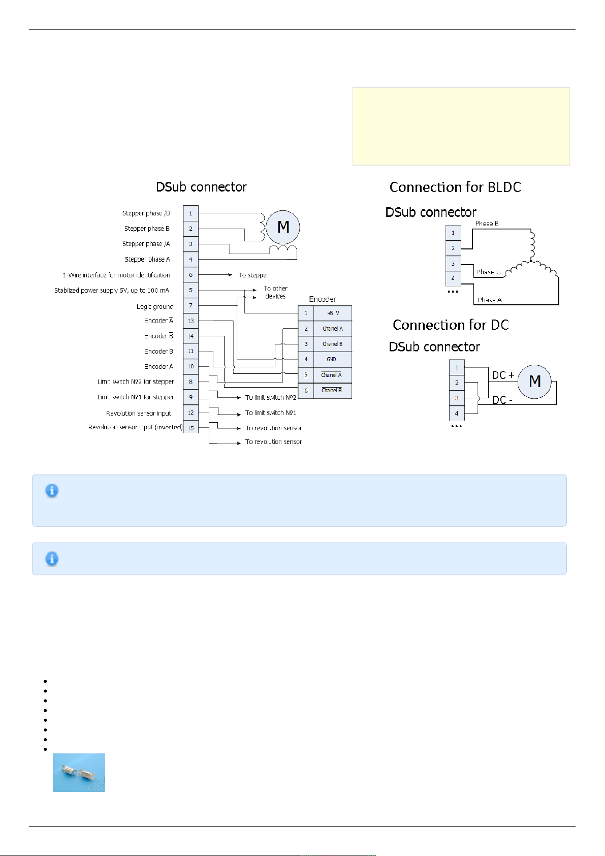
General diagram of positioner and encoder connection using Dsub connector.
Note. If A and B encoder channels work in open drain mode, some extra pull-up of encoder outputs to 5V power
voltage using the resistors may be required at high rotation speeds in order to provide the maximum signal
transmission speed (see Operation with encoders ).
Note. Only firmwares 4.1.0 and older support BLDC.
Example
Consider the connection of the two-phase stepper motor Nanotec ST5918L3008-B with encoder CUI INC AMT112S-V to controller
8SMC5-USB.
Preparation
To get started, we need:
Motor;
Encoder;
Pinout of D-SUB connector for 8SMC5-USB;
Motor datasheet ;
Encoder datasheet ;
Soldering equipment: soldering-iron, wires, flux, solder, nippers, heat shrink tubes of different sizes;
Screws M2.5x6 for fixing the encoder;
D-SUB cover + connector (male) and wires for cable manufacturing;
Page 19 / 345
Page 19 / 345
Connecting the motor and encoder to the controller
Before you begin, assemble the encoder in accordance with the appropriate instructions.
The motor without encoder. Note 2 holes M2.5 to which is usually attached an encoder
Motor with attached encoder
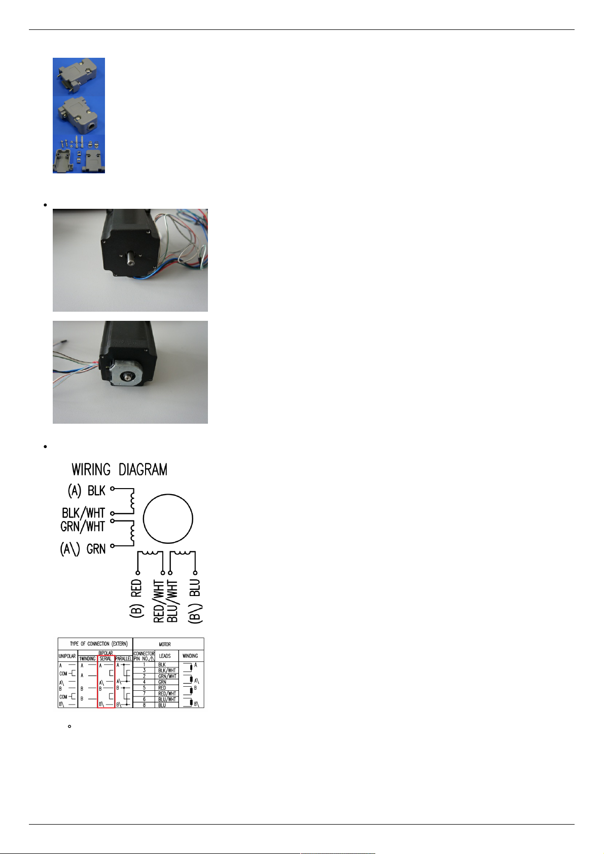
Let us look in the specification of the engine and find the wiring diagram (for Nanotec ST5918L3008-B it is at the bottom right in
the specification):
Motor contacts
Connection type
There exist serial and parallel winding connection and each type allows to obtain various characteristics for the motor. We
will connect the windings in series (red frame on the picture). To do this, wires having two colors BLK/WHT and GRN/WHT,
as well as RED/WHT and BLU/WHT must be connected to each other in pairs. Next, you need to put in accordance A, not A,
B, not B pins of controller to contacts of motor windings ST5918L3008-B: black, green, red, blue. One winding is a
connection of A and not A or B and not B. After the connection between a two-color wire, you will get that one winding of
the motor is black - green connection, other is red - blue. Therefore, matching contacts will be the follows: black - A, green
- not A, red - B, blue - not B. It can be seen in the picture above Connection type.
Page 20 / 345
Page 20 / 345
To connect encoder, open its datasheet and find 5 contacts on encoder connector: A+ (channel A), B+ (channel B, shifted
relative to A by 90 degrees), Z+ (rev counter), 5V, GND. They should be taken from the encoder as 5 separate wires and
put together with the wires from the motor as they then go to a connector. CUI INC AMT112S-V encoder has 18 pin input,
therefore it is needed to make a cable with the same connector on the end to output necessary signals:
Encoder contacts A+, B+, Z+, 5V and GND corresponds to 10, 11, 12, 5, 7 pins of D-SUB male connector respectively.
For convenience, use the next tables (the number in parentheses indicates pin on the corresponding connector):
Encoder pin D-SUB pin
A+ (10) Encoder A(10)
B+ (8) Encoder B(11)
Z+ (12) Revolution sensor input (12)
5V (6) Output 5V, 100 mA (5)
GND (4) Logical ground (7)
Motor pin D-SUB pin
A (BLK) phase А (4)
not A (GRN) phase not А (3)
B (RED) phase B (2)
not B (BLU) phase not B (1)
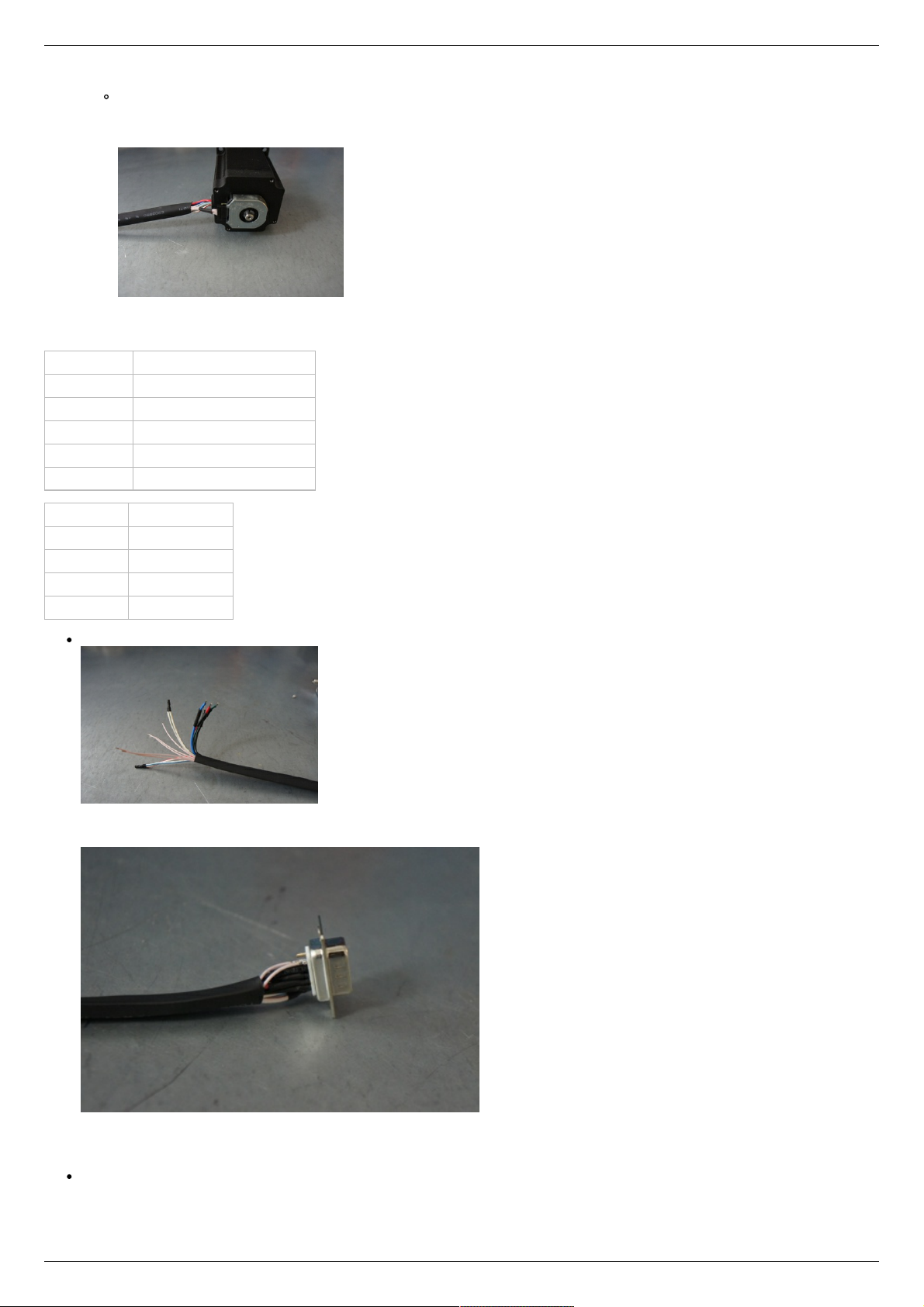
Solder the above contacts to D-SUB male connector:
The wires from the motor and encoder in a heat shrink tube. Note the presence of small heat-shrinkable tubes for wires going to
the motor windings (BLK, GRN, RED and BLU), as well as two-colored wires joined together (BLK/WHT and GRN/WHT, RED/WHT
and BLU/WHT). The thin wires are an encoder contacts (5 pcs).
Ready cable from the motor with the D-SUB connector on its end
Recommendation: use heat shrink tubes of a small diameter (2-3 mm) while soldering contacts to D-SUB connector, and large
diameter to skip through them all the wires coming from the motor and encoder. Put them before soldering.
Put D-SUB connector into the cover.
Page 21 / 345
Page 21 / 345

Now you can connect it to 8SMC5-USB.
Description and profile settings are given in the next chapter Manual profile setting .
Page 22 / 345
Page 22 / 345
3.3. Manual profile setting
Introduction
Getting started
Nominal current setting
Basic parameters setting
Hardware limit switches setting. Homing.
Encoder parameters setting
Setting the kinematic characteristics of the
controller
Working with user units
3.3. Manual profile setting
Introduction
All necessary parameters are set after motor connection (see Example of a
motor connection where the Nanotec ST5918L3008-B motor connection is
described). There we will consider the setting of the profile for Nanotec
ST5918L3008-B stepper motor.
Getting started
Install and run XiLab (see One axis configuration).
Load the profile with default settings. To do this, open + Settings ->
Restore from file ... + and select xilabdefault.cfg file from XiLab folder.
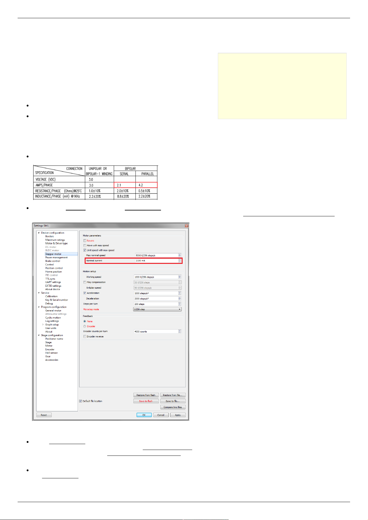
Nominal current setting
Initially, it is needed to set a correct current in motor windings:
From the specification find the phase current 2.1 A - this is the maximum current for the motor in case of serial winding
connection:
Being in the Settings window, open Stepper motor tab. There are such parameters as rotational speed, acceleration, driving
mode, etc. (seeSettings of kinematics (stepper motor) for additional information). In Motor parameters-> Nominal current field
you should specify the value of the phase current not exceeding 2.1 A:
Basic parameters setting
In the Working speed field we will specify a rotation speed. The recommended speed is not more than 1000 s/sec at the first
start. In the same window you should type Max Nominal Speed (5000 s/sec is reasonable value for majority of motors and
motorized stages) and mark Limit speed with max speed. This setting is necessary to limit the motor speed since some
mechanical systems can be designed for low speed, and fast rotation can lead to severe wear of motor/stage mechanics.
In the motor specification we find the number of steps per rotation. For our motor this value is equal to 200 steps. Specify it in
the Steps per turn field. Usually, the value of one pitch in degrees is listed in motor description, on the basis of which you can
Page 23 / 345
Page 23 / 345
calculate the number of steps per revolution, knowing that one revolution consists of 360 degrees.
Make sure that movement to the right from the main window of XiLab corresponds to the movement to the right of the stage. If
not, then check the box Reverse field Stepper motor -> Motor parameters .
Hardware limit switches setting. Homing.
Note. This section describes the using of motorized stages with hardware limit switches. If your system is not
provided with hardware limit switches, it is recommended to disable stop by limit switches in settings. To do this,
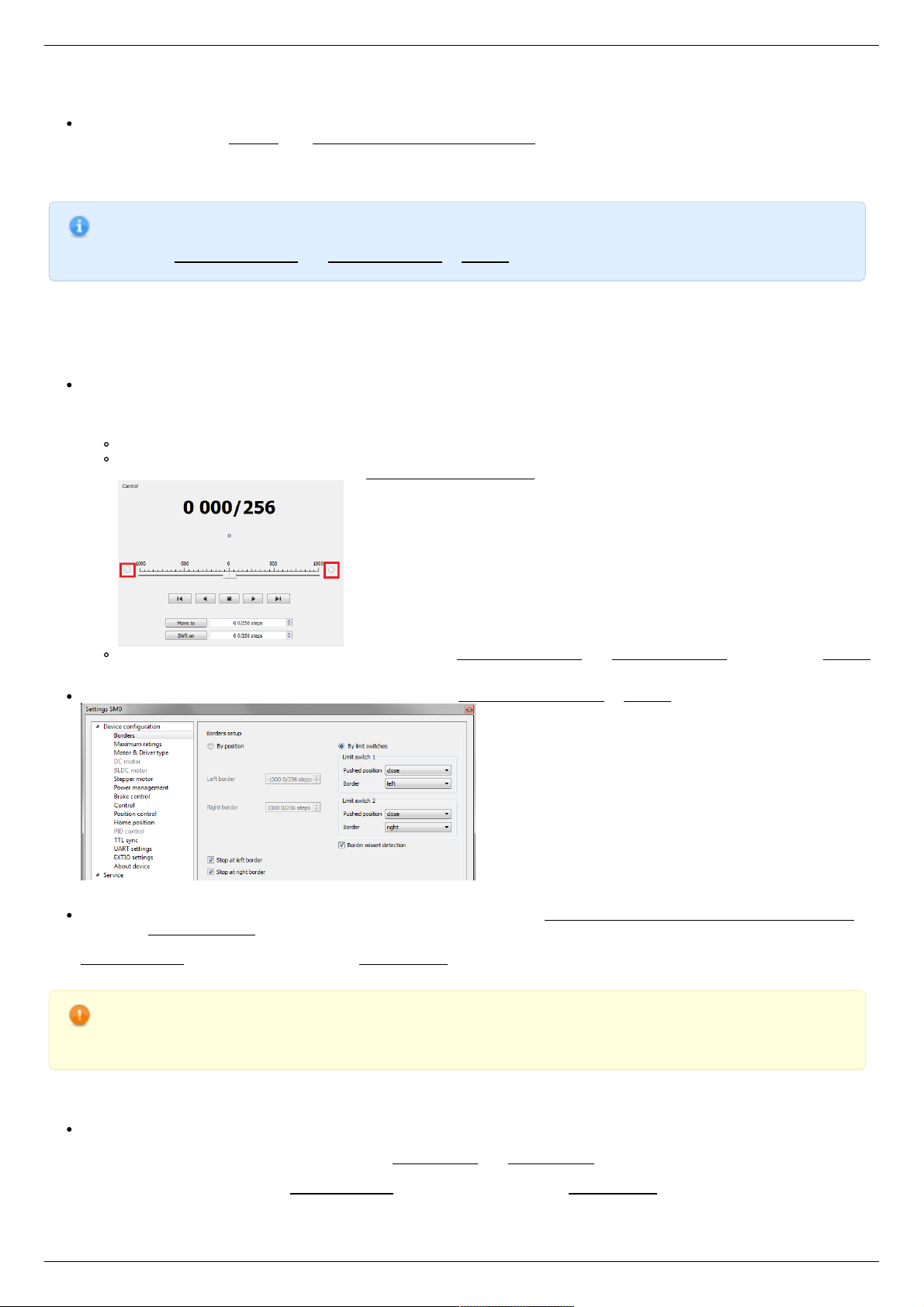
unmark Stop at right border and Stop at left border in Borders tab.
There are positioners with limited (translators) and an unlimited range of motion (rotators). The limitation of movement range can be
done by position or with limit switches using. When you work with translators if its limit switches are configured incorrectly there exists
a risk to break down mechanics, since moving part can try to go out of motion range. Rotators do not have such problem. Moreover, it
should be kept in mind that rotator may have only one limit switch.
To work with limit switches you must specify which one will be left and right. Sometimes it is unknown in advance and we only
know that both switches are connected and fire if the corresponding limit of the motion range is reached. The stage jam is
possible if the limit switches are configured improperly. Therefore, the controller supports just a simple detection of incorrectly
configured limit switches, shutting down the movement on both of them. Please make sure that:
The stage is far from limit switches;
Switches polarity is configured correctly (limit switches indicators are off in the main window of XiLab). In the case of
incorrect settings, change their polarity (Borders -> Pushed position ), indicators should go out.
Shutdown mode is activated on both of limit switches ( Stop at right border and Stop at left border are marked in Borders
tab).
Mark the flag detecting improper connection of limit switches Border misset detection in Borders tab.
Tab with limit switches settings
Controller can switch to Alarm state after false limit switch response, if Enter Alarm state when edge misset is detected is
enabled in Maximum ratings tab. It is recommended to enable it. Start the movement in any direction from the main window of
XiLab up to Alarm state or stopping by the limit switch. When an Alarm occurs you need to reverse limit switches by changing
Borders->Border with reversed values in the Stepper motor tab.
Warning. The protection against mistaken limit switches connection doesn't guarantee the complete solution of the
problem, it only makes the initial configuration procedure easier. Don't start the movement with mixed up limit
switches if any of them is active, even if the protection is on.
There are still two ways to determine which of the limit switch is right and which is the left:
You need to know how each of the limit switches is connected to the positioner. When loading a profile with the default settings,
switch connected to pin 9 of the D-SUB connector is considered as left, while switch connected to pin 8 - as right. Their location
relative to the positioner is configured in the fields Limit switch 1 and Limit switch 2 (see screenshot above). Start the system at
the low speed (<100 ш/с) when it is far away from limit switches. If the direction of movement to the switch in a real setting
differs from the expected, change Borders->Border values with reversed in the Stepper motor tab.
Page 24 / 345
Page 24 / 345
If it is possible to get limit switches activate them and note the correspondence between indicators in XiLab and each particular
switch. Then start the system at the low speed (<100 ш/с) when it is far away from limit switches and make sure that the
system moves to the right switch. Compare this to what you see in the main window of XiLab. If the direction of movement to
the switch in a real setting and in the main window differs, change Borders->Border values with reversed in the Stepper motor
tab.
For detailed information refer to motion range and limit switches .
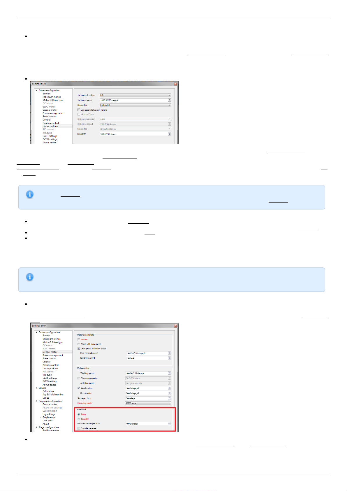
Controller has a useful function called automatic Home position calibration to set the initial position of the motorized stage.
We will consider the most simple configurations with a single phase only. Start from the setting of the 1st phase speed which is
approximately 5-10 times lower than Working speed. It is necessary for higher precision of automatic calibration procedure. In the filed
Stop after specify the limit switch to make the stage reached one of the limit switches during the calibration (direction is selected in the
1st move direction). In the field Standoff specify number in steps, for which stage must be driven away from the limit switch. Click Ok
or Apply.
Note. Standoff value is signed. Positive direction is right. That is, if the auto-calibration procedure is set up on the
right limit switch, then in order to move stage away to the left you should type negative value in Standoff field.
Start the automatic calibration by clicking Go home in the main window of XiLab. The result of it is a movement of the positioner
to the specified limit switch with a relatively low speed and the shift away from him to the value specified in the field Standoff.
After completion of the calibration process, press Zero in XiLab to set the origin of coordinate system for your stage.
Repeat the calibration process again. The stage must return to the zero position. Please pay attention that there can be slight
deviations from zero connected with calibration procedure error.
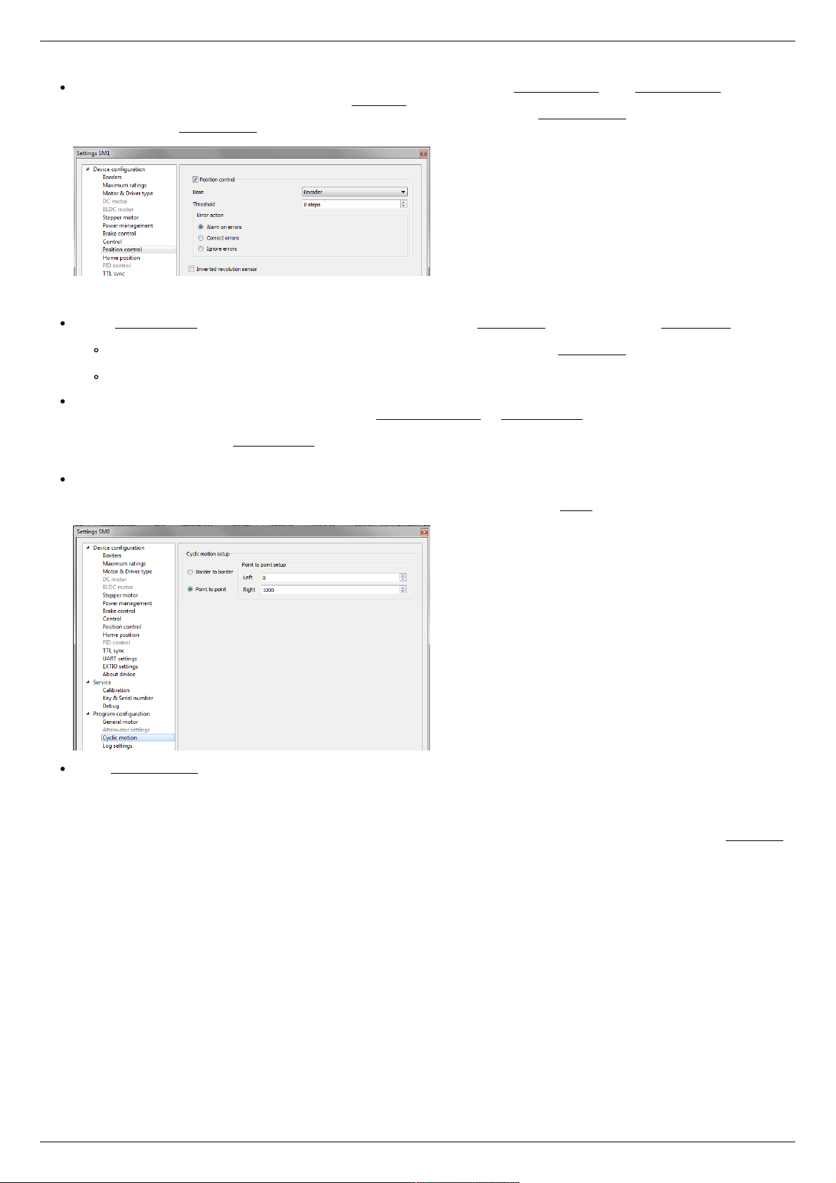
Encoder parameters setting
Note. This section describes the using of motor with encoder. If you motor without an encoder, the parameters
described below can be left unchanged.
Any encoder has Pulse Per Turn - PPT parameter (sometimes it is called PPR - Pulse Per Rotation). For correct operation of
the encoder with controller you should enter the number of encoder counts per revolution, which is equal to 4xPPT in the
Encoder counts per turn field in XiLab. For example, if your encoder has 1024 pulses per turn, specify 4096 in the Counts per
turn:
Start the motor rotation from the main window of XiLab. If everything is configured correctly, the green indicator ENCD will light
in the bottom of window. If ENCD has yellow color, you should mark Encoder reverse in the Stepper motor tab. Red color of
EDCN points to the problem with encoder position recalculation..
Page 25 / 345
Page 25 / 345
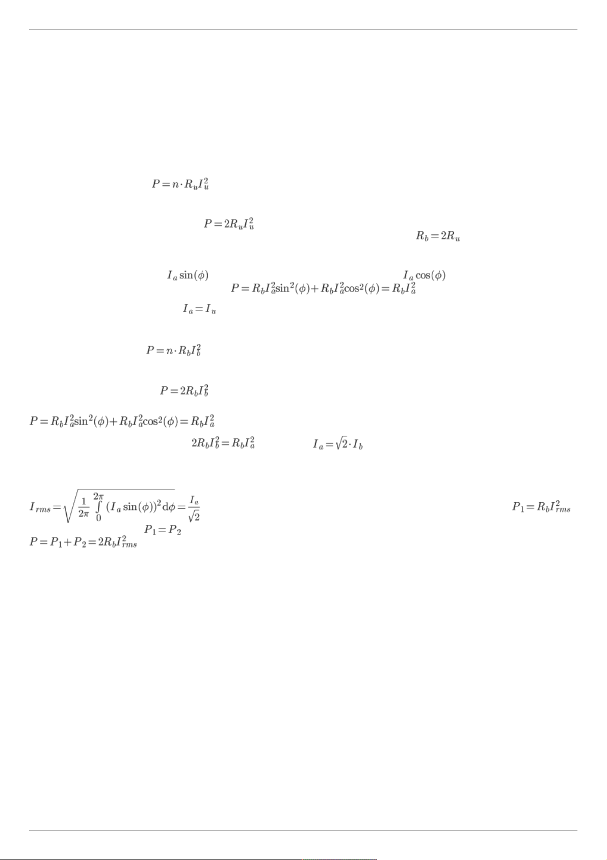
It is possible to activate the position control by encoder. To do this, in the tab Position control mark Position control and specify
allowable error in terms of encoder counts in the Threshold field. Then, when a mismatch between position and encoder counts
occurs, indicator SLIP will light in the bottom of XiLab main window. Beyond this, if Alarm on errors is marked, the controller will
go to Alarm state. Correct errors allows you to start closed loop control, when the difference between real position and encoder
position is compensated.
Setting the kinematic characteristics of the controller
In the Stepper motor tab you may specify a necessary acceleration ( Acceleration) and deceleration ( Deceleration) for your
stepper motor. The process of optimal values selection is the next:
Starting from default values make small shifts (start and fast stop) with gradual Acceleration increase until the movement
become unstable and disrupted sometimes. Take acceleration equal to about half of this value.
The deceleration can be configured about 1.5 - 2 times higher than acceleration.
If in your mechanical system moving to the desired position on the left and on the right is not the same, and there is play, it is
possible to eliminate this ambiguity. To do this mark Play compensation in Stepper motor and type number greater than play
value. The sign of this setting determines the direction of moving to the position. Positive sign means move from the left while
negative - from the right. In Antiplay speed field set the speed of compensation movement. This value should be low ( 50 s/sec
is enough) in order to avoid "drifting" during play compensation.
After the basic configuration of the positioner/motor, you can increase working speed. It can be done experimentally like the
process of acceleration setting, i.e. you should take its value about 2 times lower than value at which there is unstable
movement. To test the stability of the rotation it is recommended to use the function Cyclic in XiLab main window. Make sure
that you set it previously.
In the Microstep mode field we recommend to enter the value 1/256.
Working with user units
Often it is uncomfortable to work with the steps and microsteps and more convenient units are preferable. For this reason, the
controller can recalculate the coordinates in the usual units, for example in millimeters or degrees. It can be done in the tab User units ,
where you should specify the size of the step and the corresponding measurement unit. For more information, refer to relevant
documentation paragraph.
Configuration of the operating profile complete.
Page 26 / 345
Page 26 / 345
3.4. Calculation of the nominal current
In order to stepper engine gave maximum torque, but it does not overheat, it is important to specify such technical characteristic as
the rated current.
The greater a current in the motor winding, the greater the torque at the axis. It is important to remember that with an increase a
current flowing through the winding, thermal power released by the motor increases. So the engine could operate for a long time
allocated to thermal power (Joule heating) must be less power dissipation. Power dissipation can be calculated on the basis of
documentation on the engine.
Calculation based on the parameters of unipolar full step mode
Power dissipation is equal to , where Ru - the resistance of the winding in unipolar mode, Iu - current through the
winding in unipolar mode, n - the number of simultaneous windings.
Consider, for example, ST2818M1006. The table in the documentation shows that in full step mode simultaneously running two
phase (n = 2) in the unipolar mode, i.e. . The motor controllers support only bipolar control mode. To switch from a
unipolar to a bipolar mode, connect each phase windings in series, the resistance will increase, , where Rb - the resistance
of the series-connected windings in the bipolar control mode.
The motor controllers control algorithm is capable of operating in a microstepping mode and maintains the current so that the first
winding current varies in function , in the other winding current varies in function , where Ia - current amplitude.
Thermal power released two windings at any time
It follows from the foregoing that the
Calculation based on the parameters of bipolar full step mode
Power dissipation is equal to , where Rb - the resistance of the winding in bipolar mode, Iu - current through the winding
in bipolar mode, n - the number of simultaneous windings.
Consider, for example, ST2018S0604. The table in the documentation shows that in full step mode simultaneously running two phase
(n = 2) in the bipolar mode, i.e.
Thermal power dissipated in the motor windings that managed by motor controller, still is
We obtain the equation equating power . We find that
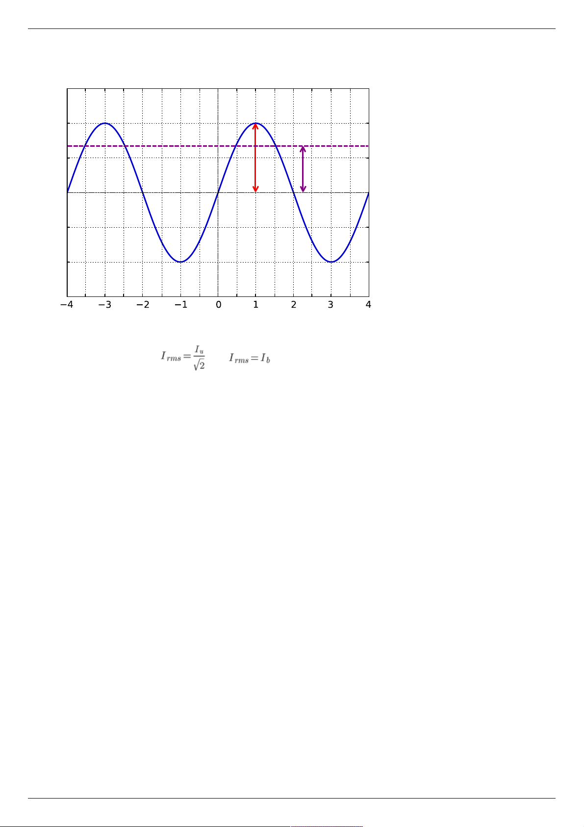
The relationship with an rms current
Alternating current in each motor winding can be characterized by its rms value in the period
. Thermal power of one winding is associated with an rms current through it .
Both windings are identical . The total thermal power of the engine that is run by control by motor controller controller
Page 27 / 345
Page 27 / 345
Steps
Current
I
a
I
rms
It follows from the foregoing that , also
Setting the nominal current
Motor controller are capable of taking the nominal current value as a current amplitude or as rms. The choice of which way to interpret
the input value of the nominal current is determined by the absence or presence corresponding flag ENGINE_CURRENT_AS_RMS in the
EngineFlags engine_settings structure. When setting the nominal current in XILab should properly specify how the current is
interpreted. Motor controllers in this case will provide the maximum torque without overheating the engine.
For all Standa motorized positioners prepared configuration files that contain the specified nominal current as rms. The corresponding
flag is set. Thus the engines operate at optimum settings.
Page 28 / 345
Page 28 / 345
3.5. Possible problems and solutions
Controller is not found in XiLab
Unable to rotate the motor by the controller
Controller has Alarm state
Motor vibrates without rotation
Mechanical jamming.
When using the libximc library and Linux with kernel version less than 3.16, there are possible hanging of the operating
system
3.5. Possible problems and solutions
Here is a list
of common
problems
and possible
solutions
that we
offer to our
users. Your
case may be
the same
mentioned
below, then you will quickly find a solution, otherwise, send your questions with a detailed description of the problem to tech support:
Ask a question
Send an e-mail: 8smc4@standa.lt
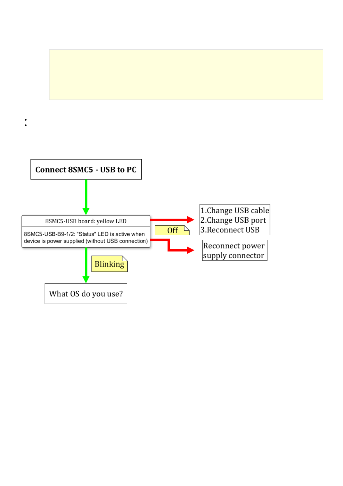
Controller is not found in XiLab
Solution:
Comment to the diagram:
8SMC5-USB-B9-1 - one axis system
8SMC5-USB-B9-2 - two axes system
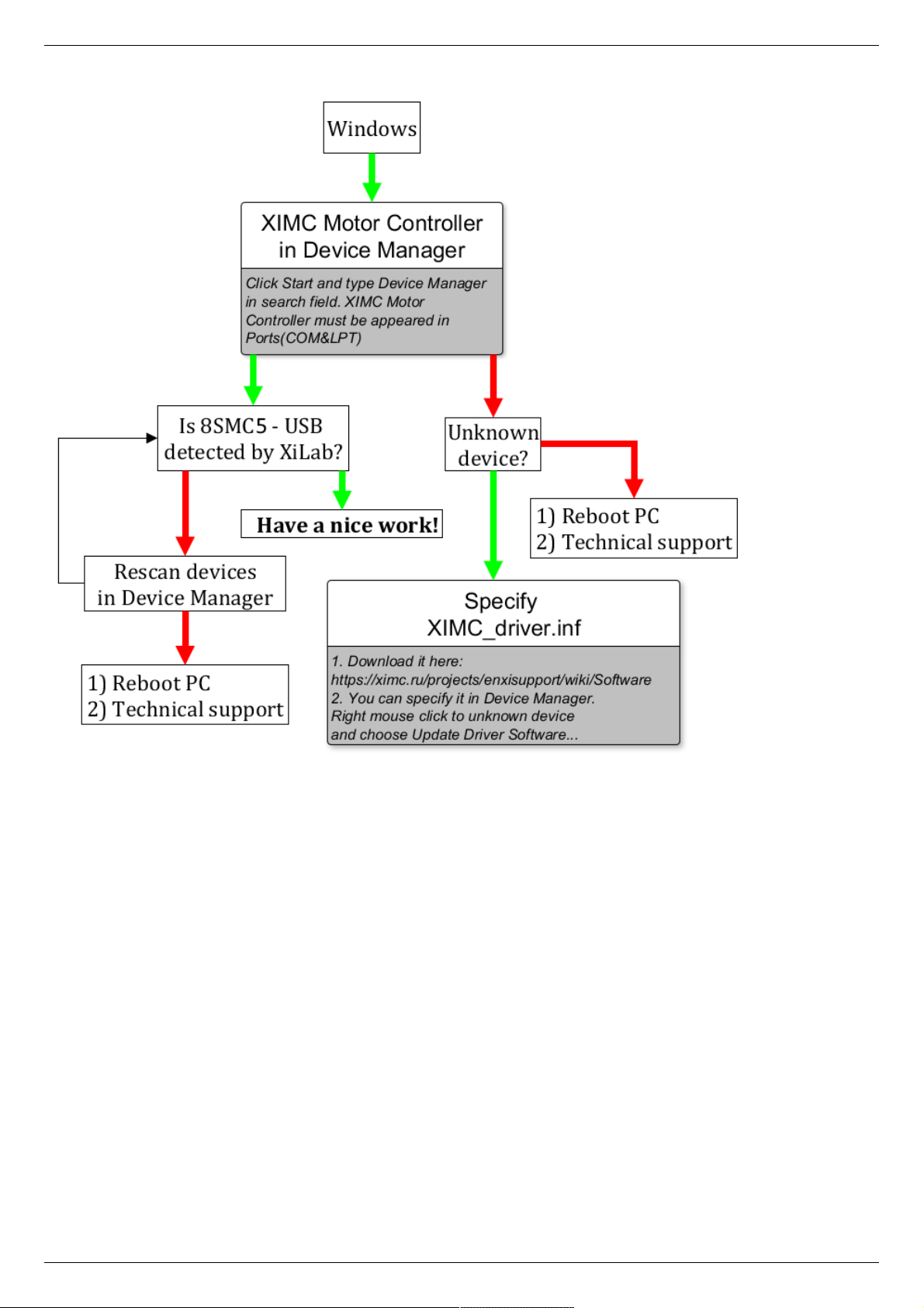
The following decision maps show the actions for different operating systems.
Windows:
Page 29 / 345
Page 29 / 345
Linux:
Page 30 / 345
Page 30 / 345
 Loading...