

STAMPFL JUNIOR 1D Assembly Manual
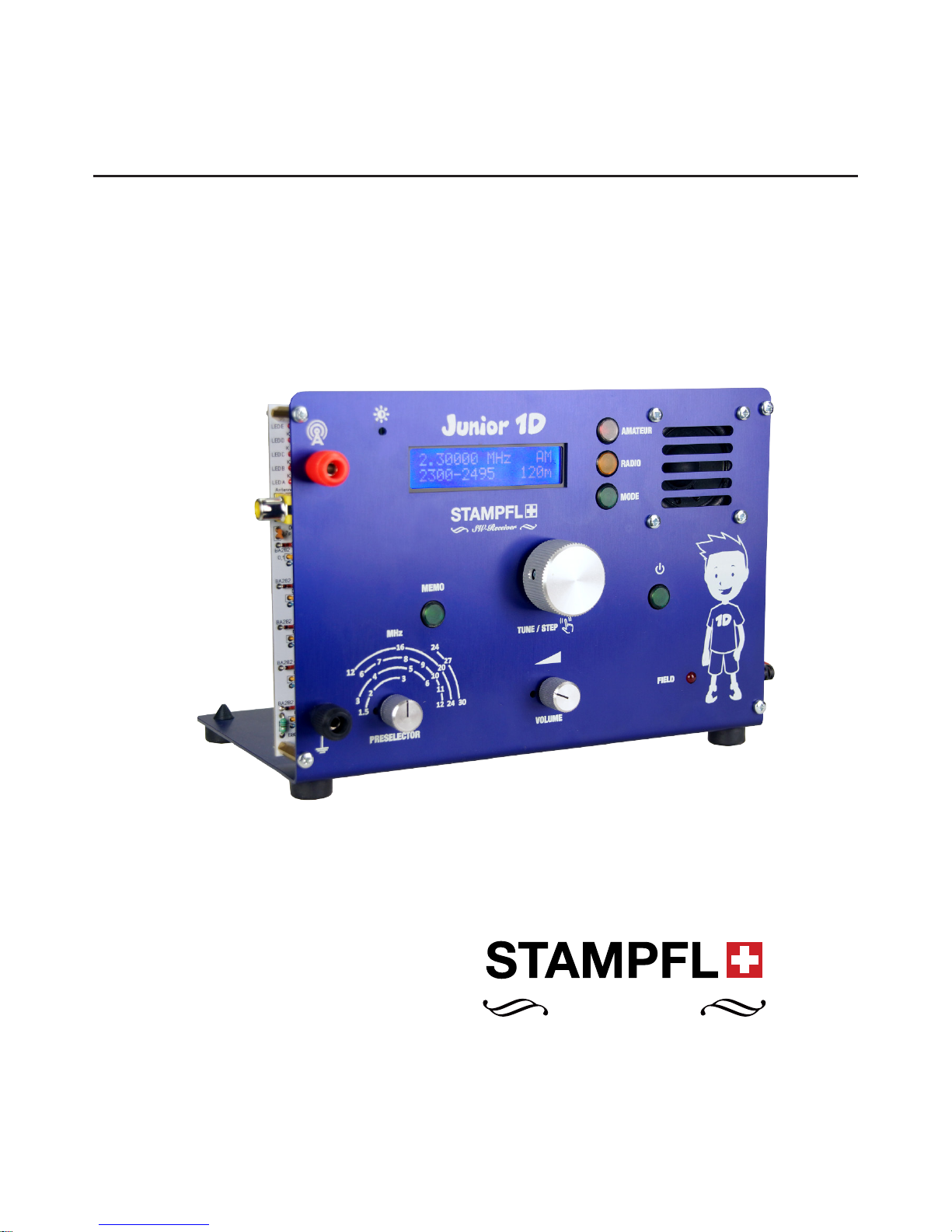
SHORTWAVE RECEIVER KIT
DOPPELSUPER, 10.7 MHZ-455 KHZ AM/SSB
1.5 - 30 MHZ
ASSEMBLY GUIDE
JUNIOR 1D
V. 1
29.08.2017
HAM ELECTRONICS
TABLE OF CONTENTS
EDITORS NOTES
TOOLS
• Screwdriver
• Flatnose Pliers
• Electric Soldering Iron
• Multimeter
• Insulated Pliers
• Small Pliers 2mm
• Fine Tweezers
• Magnifying glass
Pictures are in high
resolution and can be
enlarged.
GUIDANCE FROM:
• HB9KOC Heinz Stampfl
• HB9QN Rolf Hasler
• Mario Graf (grafdesign.ch)
• Carmen Sommer
Many thanks for the support!
THERE IS NO WARRANTY TO THE KIT!
If short circuits and smoking heads occur please use “FIRST AID”
CONTENT POINTS
ADJUST THE DISPLAY CONTRAST P 23
SYSTEM CHECK P 24
RECEPTION CHECK P 25
SPEAKER ASSEMBLY P 26
BUSHING ASSEMBLY P 27
PCB MOUNTING P 28
PCB CENTERING P 29
BATTERY PACK ASSEMBLY P 30
WIRES ON BACK P 31
PRESELECTOR BUTTON P 32
JUNIOR 1D BLOCK DIAGRAM P 33
JUNIOR 1D INPUT CIRCUITS P 34
JUNIOR 1D HF PART P 35
JUNIOR 1D DDS VFO P 36
JUNIOR 1D ON/OFF CIRCUIT P 37
CONTENT POINTS
RESISTORS P 1-4
DIODES P 5-6
BLOCKING CAPACITORS P 7
INDUCTORS P 8
CERAMIC CAPACITORS P 9
IC P 10-11
MISCELLANEOUS P 12-13
ELECTROLYTIC CAPACITORS P 14
DDS MODULE P 15
PUSHBUTTONS P 16
DISPLAY ASSEMBLY P 17
TOROIDS P 18
POTENTIOMETERS (POTI) P 19-20
BACK P 21
POWER CHECK P 22
UUUPS! SHORT, MALFUN
C
T
I
O
N, PROBLEMS? - FIRST AID (HELP INSTRUCTION GUIDE)
1. Write a detailed Report
2. Make Photos of your kit and attach it to the E-mail
2x (front and back of the print)
3. Initiate calming measures
4. Wait for Help
E-MAIL ADDRESS
info@heinzstampfl.ch
- FIRST AID - DO
N
’
T
W
O
R
R
Y
E
VERYTHING IS GO
N
N
A
B
E
F
I
N
E
- FIRST AID - DO
N
’
T
W
O
R
R
Y
E
VERYTHING IS GO
N
N
A
B
E
F
I
N
E
JUNIOR 1D
Again and again I had requests from Junior1 builders,
whether digital frequency displays or reception areas can be
extended. I advise against these interventions. The questions
motivated me, however, to develop Junior1 further. J1D is
the successor model of Junior1, specially developed for HAM
RADIO enthusiasts without HF measuring station.
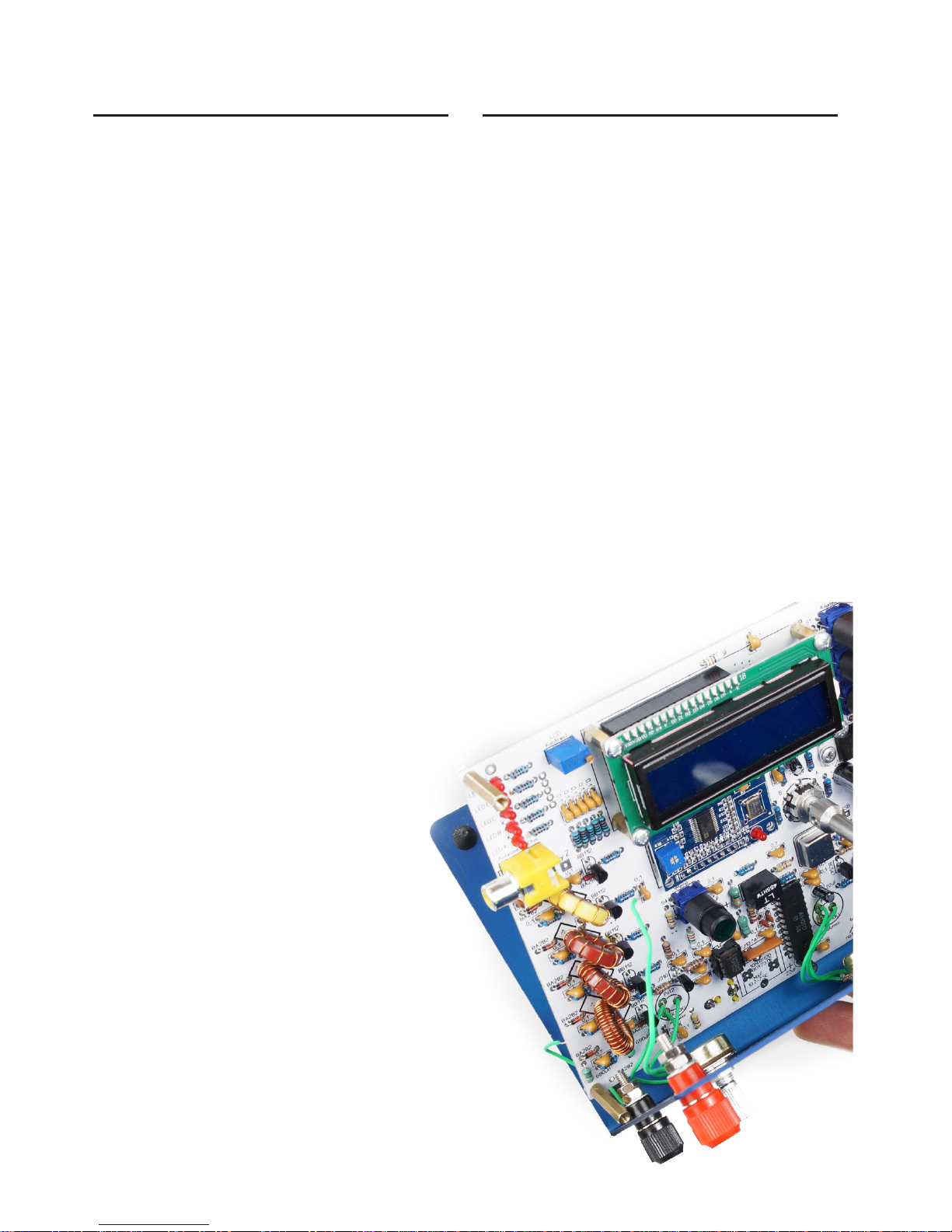
The only adjustment work is to adjust the LCD
Display contrast!
J1D shows the following changes: An Atmega AT644 microprocessor is used as a “brain”. This provides the control commands
for the DDS, the LCD display and the preselector. All buttons as
well as the redary encoder are also queried at the AT644. The
reception concept of Junior1 has proven itself, which is why it
was largely adopted in J1D. However, the large reception area
requires a completely new input circuit. The preselector realized
with high-quality ring cores provides a good mirror frequency
suppression. At the output of the preselector, the RF voltage is
converted by the field effect transistor in a low-impedance manner and supplies this voltage to the first mixer. At the output of
the mixer, the first IF is at 10.7 MHz. If you want to upgrade the
receiver, the 10.7MHz ceramic filter can be replaced by an 8-pole
quartz filter. The board is ready to handle it.
The first IF enters the A4100D. This converts the 10.7MHz to the
2nd IF of 455kHz. The automatic
Amplification control, demodulation and LF preamplification
Also takes the A4100D.
An SSB reception comes by direct radiation in the ZF amplifier.
The superimposed oscillator is realized with a BC547 and a ceramic resonator.
By this direct method, however, the control range is lower and
there is a continuous glow of the “Field LED”. In addition, distortion of the SSB reception is possible with too strong signals.
An LM380 in conjunction with a 4Ohm loudspeaker guarantees
a strong audio reproduction.
The operation of J1D is reduced to the essentials.
The tuning steps can be selected by pressing the redary encoder knob. The “MEMO button” allows you to store the last set
frequency and type of demodulation before switching off the
device. The pre-programmed reception frequencies are selected
by pressing the “Amateur” and “Radio” buttons.
The “Field LED” shows the relative reception field strength and
serves as a tuning aid for the preselector.
A new battery compartment is also available.
Conclusion: J1D is a powerful SW receiver with high sensitivity
and frequency stability in a attractive design. Before we begin
now with the construction, read these important points:
1. The pushbuttons must be used in the correct position. The
stage on the button is marked as a line on the board.
2. Check the correct resistance before soldering the resistors
Value.
3. The electrolytic capacitors are absolutely polarized
soldered. The positive pole is the longer wire and the
Negative pole is marked on the housing.
4. Take your time and follow instructions.
5. Make sure you do not create any short circuits because of
Soldering eyes.
If you want to mount the IC’s (except A4100D), which is not
absolutely necessary. Frames can be used. If so take special
caution to check all pins for alignment.
REMARKS TECHNICAL SPECIFICATIONS
As with any other electronic circuit, the development of
Junior 1D was the greatest challenge to find the best possible
compromise. At a Product of this type should also have its
advantages and disadvantages be addressed.
Local Oscillator:
The local oscillator is obtained directly from the DDS. Unfortunately, DDS oscillators in this price class have their disadvantages. In addition to the main signal, many weak secondary
frequencies are included in the spectrum. This is shown by
disturbed reception areas. On: 5.1-8-8.5-9.4-10.4-11.7MHz,
this effect is strongest. When the antenna is connected, however, most “ghost signals” disappear under the noise. A plus
is the good phase noise of the LO, because the DDS output
signal is derived directly from 125MHz clock.
SSB reception:
In SSB reception, the upper and lower side bands is received
at the same time (DSB). The bandwidth is 6kHz. Only one SSB
filter with 2.7kHz bandwidth and with the appropriate overlay
frequencies would allow real single-page reception here.
SSB Smaller dynamics:
By directly feeding the SSB superimposed frequency from
455kHz into the A4100D, the AGC (Automatic Gain Control)
“pulls” by about 40db. Exactly this value goes in the
Scope of control. This can happen with strong SSB
Stations as distorted playback. Here, only a weakening of the
input signal brings relief.
A great plus of J1D is its simple operation, a very good
powerful sound in AM and its high assembly security packed
in a pleasing appearance
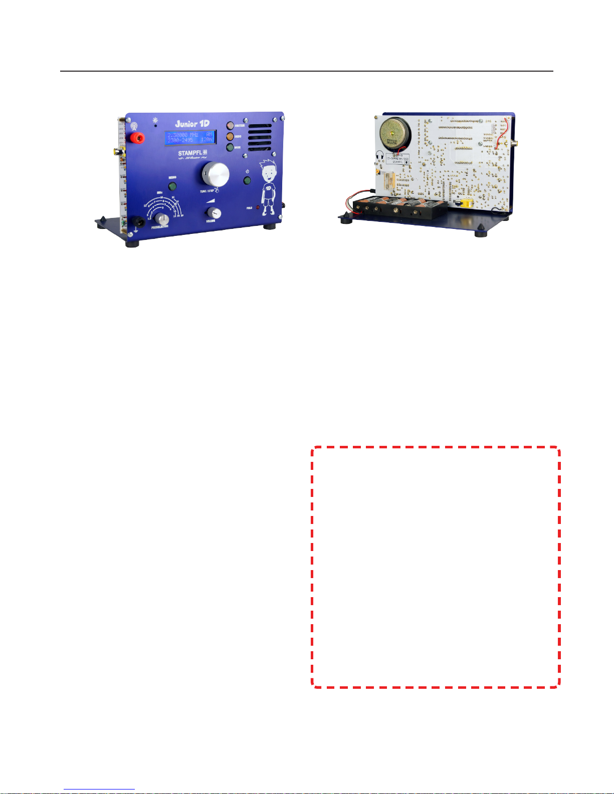
Useful tips before we start!
Put away the Speaker and not to unpack it.
Reason: The magnet can attracts small parts.
Empty all remaining plastic bags into a clean vessel.
There is no packaging system.
Have fun and success in building this Kit.
Heinz Stampfl
• reception area: 1,5-30MHz
• Modulation types: AM-DSB
• IF Filter: 10,7MHz ceramics
(Optional quartz filter 8Pol) 455kHz 6kHz BW 6Pol
• Dynamic Range AM: 95db
• Dynamic Range SSB: 55db
• SSB Method: Direct irradiation into the IF amplier
• Receiver principle: Doppelsuper 10,7MHz-455kHz
• Local oscillator: DDS(9850) 125MHz CLK
• Frequency steps: 10Hz, 100Hz, 1kHz, 5kHz, 9kHz
• Display: LCD 2x16 character
• Voltage range: 9-16V
• Power consumption: 300mA
• Battery Life: 8xAlkaline Typ AA ca.7h Akku 2100mAh ca.7h
• Height, width, depth: 150mm, 215mm, 150mm
• Weight: 0,85kg mit Batterien

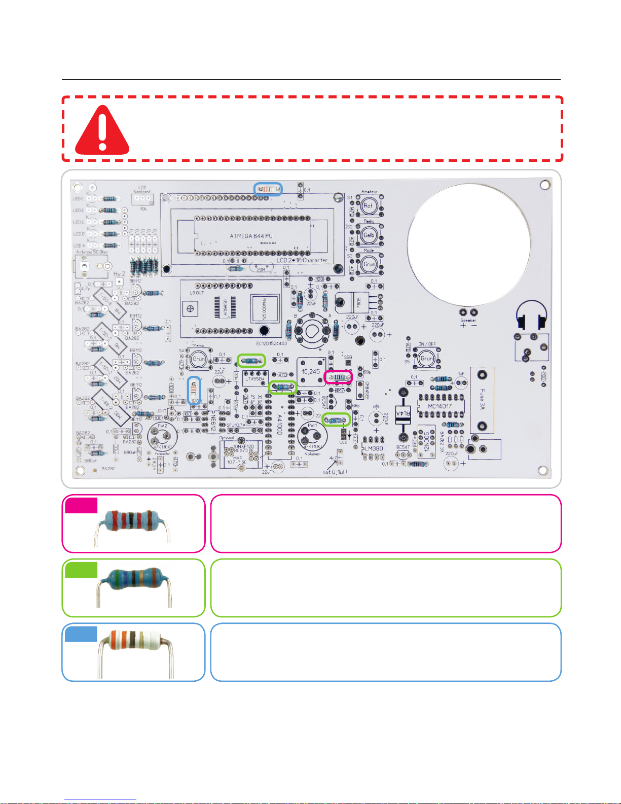
RESISTORS: 1
We first fit the flat components:
We start with the Resistors which we check for its right value before
soldering it to the Print
Metal Film Resistors: 1k
Color Code: brown | black | black | brown | brown
Metal Film Resistors: 100k
Color Code: brown | black | black | orange | brown
Metal Film Resistors: 10k
Color Code: brown | black | black | red | brown
10x
7x
12x
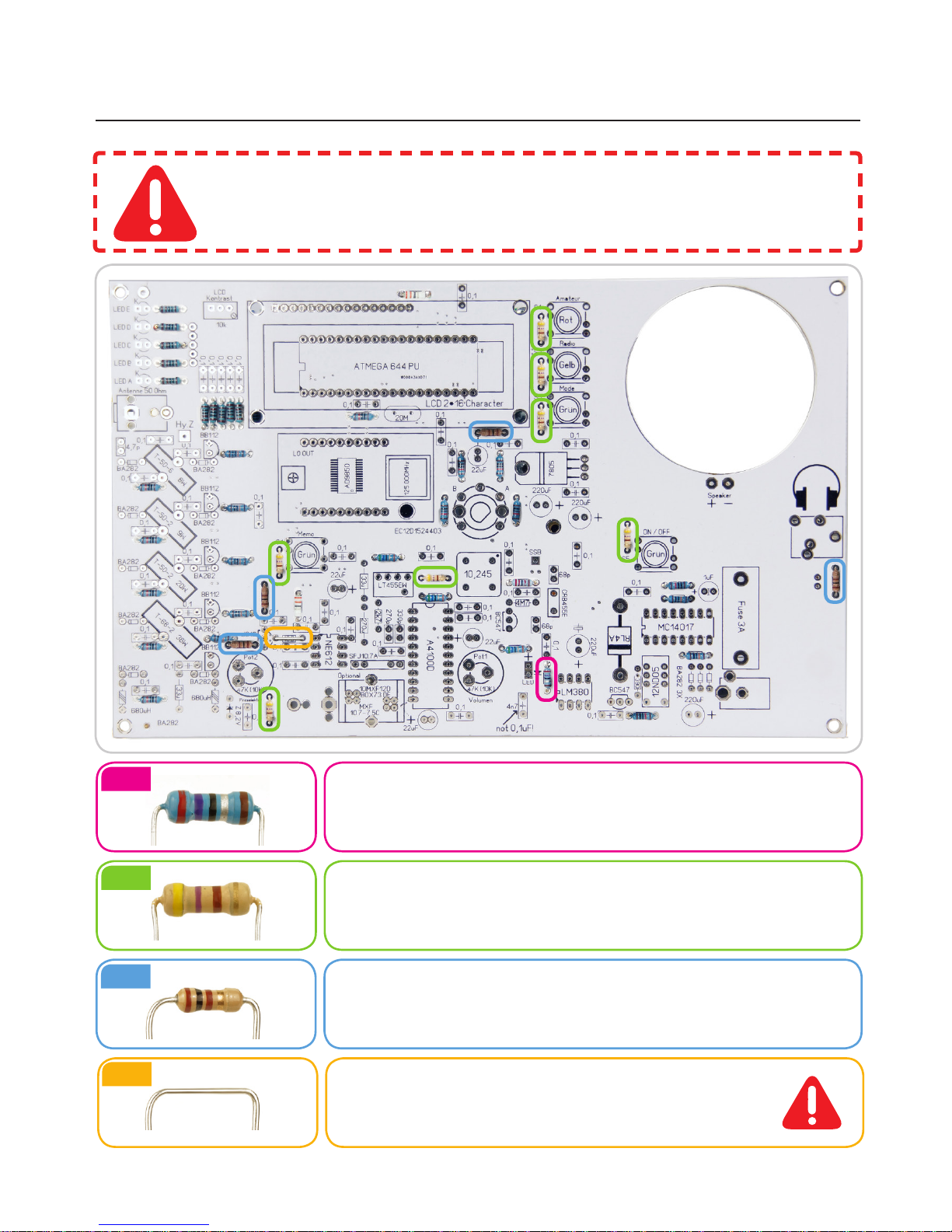
We first fit the flat components:
We start with the Resistors which we check for its right value before
soldering it to the PCB
Metal Film Resistors: 22k
Color Code: red | red | black | red | brown
Metal Film Resistors: 56R
Color Code: green | blue | black | gold | brown
Metal Film Resistors: 33R
Color Code: orange | orange | black | gold
RESISTORS: 2
1x
3x
2x
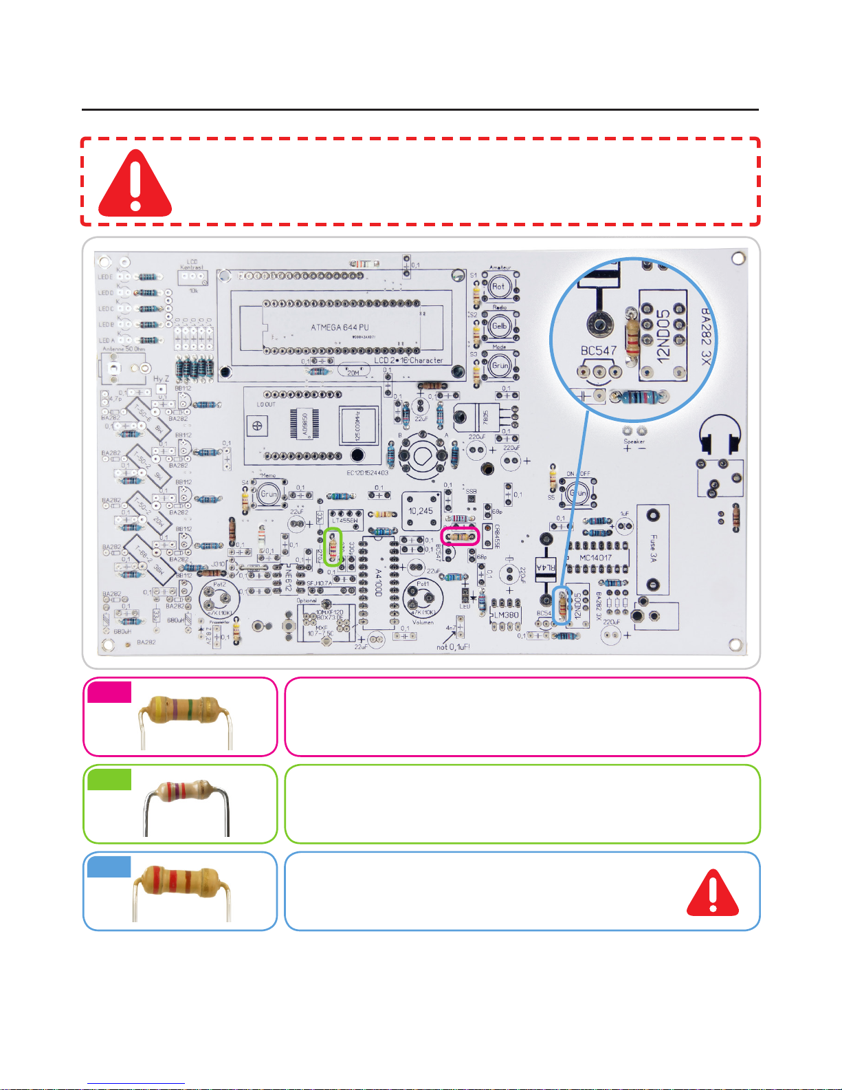
RESISTORS: 3
We first fit the flat components:
We start with the Resistors which we check for its right value before
soldering it to the PCB
Metal Film Resistors: 2,7R
Color Code: red | violet | black | silver | brown
Alignment does not matter.
Carbon Film Resistors: 470R
Color Code: yellow | violet | brown | gold
Alignment does not matter.
Carbon Film Resistors: 100R
Color Code: brown | black | brown | gold
Alignment does not matter.
1x
7x
4x
ERSATZ: Drahtbrücke
Anstelle des 100R Widerstandes!
1x
CORRECTION!:
Instead of the 390R a 220R Resistors is soldered in.
Carbon Film Resistors: 4M7
Color Code: yellow | violet | green | gold
Alignment does not matter.
Carbon Film Resistors: 2k7
Color Code: red | violet | red | gold
Alignment does not matter.
Carbon Film Resistors: 220R
Color Code: red | red | brown | gold
Alignment does not matter.
RESISTORS: 4
1x
1x
1x
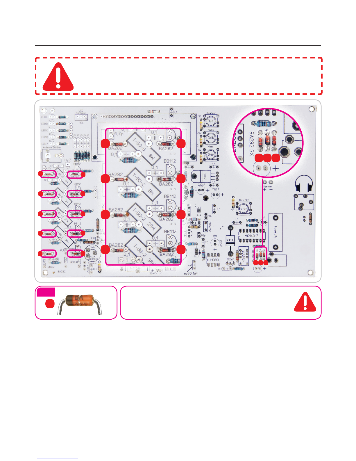
Switch diode Typ: BA282
DIODES: 5
ATTENTION!:
Keep mounting direction in mind!
13x
K
K
K
K
K
K
K
K
K
K
K
KKK
K
K
K
K K K
KK
K
K
K
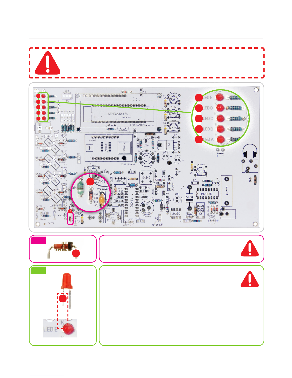
Z-Diode Type: V8V2
LED: 3mm
The shorter leg is the minus pole (C).
DIODES: 6
ATTENTION!:
Keep mounting direction in mind!
1x
5x
K
K
K
K
K
K
K
K
K
K
K
K
K
K
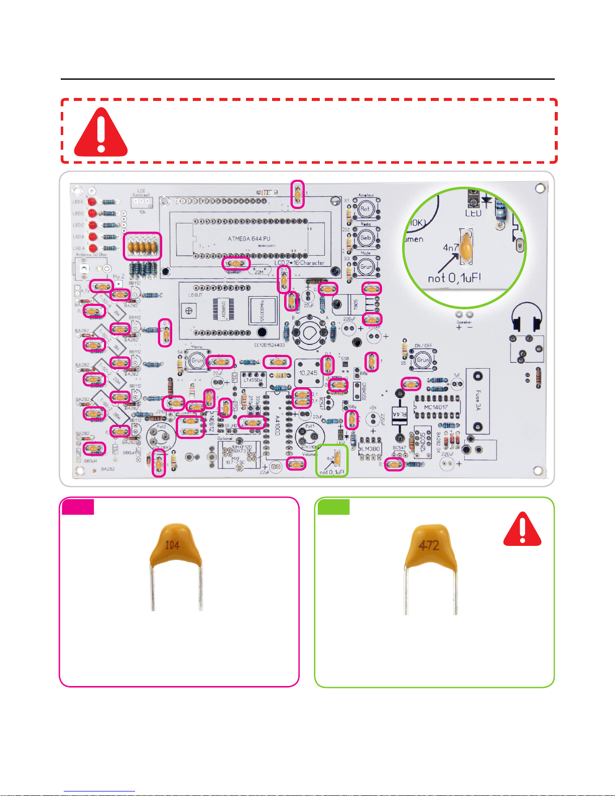
Blocking Capacitors: 0,1uF
Alignment does not matter.
In excess available!
Ceramic capacitor: 4,7nF
Alignment does not matter.
BLOCKING CAPACITORS: 7
43x 1x
ATTENTION!:
The design of the 4,7nF ist the same as the 0,1uF!
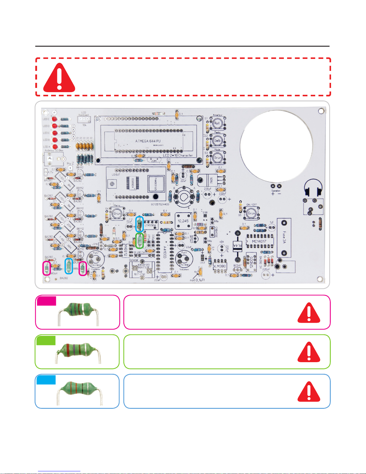
Inductors: 680uH
Color Code: blue | grau | brown | silver
Alignment does not matter.
Inductors: 33uH
Color Code: orange | orange | black | silver
Alignment does not matter.
Inductors: 270uH
Color Code: red | violet | brown | silver
Alignment does not matter.
INDUCTORS: 8
ATTENTION!:
Spool body could break!
Bend wires with care.
2x
2x
1x
2x
1x
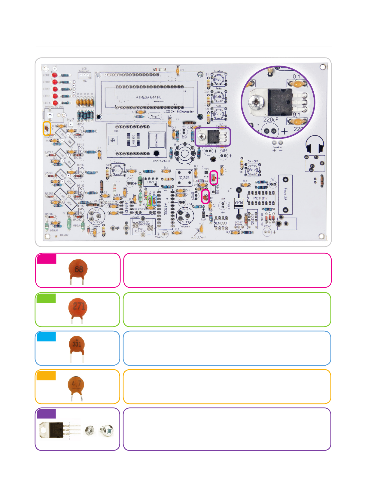
Ceramic Capacitor: 68pf
Alignment does not matter.
Ceramic Capacitor: 270pf
Alignment does not matter.
Ceramic Capacitor: 330pf
Alignment does not matter.
Ceramic Capacitor: 4,7pf
Alignment does not matter.
At the voltage regulator 7805 we bend the 3 feet at a 90
degree angle so that it is covered with the mounting hole on
the circuit board. Fix and solder using M3x5mm screw and
matching nut.
CERAMIC CAPACITOR: 9
90° 1x 1x
1x
1x
1x
 Loading...