

Stamos S-PLASMA 55H, S-PLASMA 85H, S-PLASMA 125H, S-PLASMA 85CNC, S-PLASMA 125CNC User guide
Page 1

BEDIENUNGSANLEITUNG
User manual | Manuel d´utilisation | Istruzioni per l‘uso | Manual de instrucciones | Instrukcja | Návod k použití
S-PLASMA 55H | S-PLASMA 85H
S-PLASMA 125H | S-PLASMA 85CNC
S-PLASMA 125CNC
expondo.com
Page 2

DE
INHALT | CONTENT | CONTENU | CONTENIDO | TREŚĆ
DE 3
FR
PL
EN
3
25
45
66
ES
IT
CZ
HU
87
109
131
151
Diese Bedienungsanleitung beinhaltet Beschreibungen, Bedienungsanleitungen und
grundsätzliche Wartungsvorgänge für die Stamos Germany Plasmaschneider S-Plasma
55H/85H/125H. Studieren Sie diese Bedienungsanleitung ausführlich. Ein vollständiges
Verständnis der Eigenschaften und der Einsatzmöglichkeiten des Gerätes gewährleistet
die sachgemäße Anwendung.
WARNUNG
• Schützen Sie sich selber und andere vor Verletzungen. Lesen Sie aufmerksam und
folgen Sie den Vorkehrungen.
• Nur qualizierte Personen sollten die Instandsetzung, Anwendung, Wartung und
die Reparatur des Gerätes durchführen.
• Während der Anwendung des Gerätes, halten Sie bitte jeden, speziell Kinder, vom
Einsatzort fern.
SCHNEIDEN kann Feuer oder Explosion verursachen.
Heißes Metall und Funken werden vom Plasmabogen weggeblasen.Dieser Funkenug,
heißes Metall, sowie der heiße Arbeitsgegenstand und heiße Geräteausstattung können Feuer oder Verbrennungen verursachen. Überprüfen Sie die Arbeitsumgebung
und versichern Sie sich vor der Anwendung des Gerätes, dass diese als Arbeitsplatz
geeignet ist.
• Entfernen Sie alles Brennbare innerhalb von 10,7m im Umkreis des Schweißgerätes.
• Wenn dies nicht möglich ist, decken Sie die Gegenstände penibel, mit geeigneten
Abdeckungen, ab.
• Schneiden Sie nicht da, wo Flugfunken brennbares Material treffen könnten.
• Schützen Sie sich selbst und andere vor Flugfunken und heißem Metall.
• Seien Sie aufmerksam, da Funken und heiße Materialien beim Schneiden, leicht
durch kleine Spalten und Öffnungen auf anliegende Bereiche gelangen können.
• Schauen Sie immer nach Feuer und verwahren Sie stets ein Feuerlöschgerät an
ihrer Seite.
• Seien Sie sich bewusst, dass das Schneiden an einer Decke, am Boden oder einem
Teilbereich, ein Feuer auf der gegenüberliegenden, nicht sichtbaren Seite verursachen kann.
2 3
Rev. 04.04.2022 Rev. 04.04.2022
Page 3

DE
DE
Schneiden sie nicht an geschlossenen Behältern wie z.B. Tanks oder
Fässer
Verbinden Sie die Arbeitskabel, so praktisch wie möglich, mit einer in der Nähe des
Arbeitsplatz liegenden Steckdose, um zu vermeiden, dass das Stromkabel im ganzen
Raum ausgebreitet ist und sich auf unbekanntem Untergrund benden könnte, der
einen elektrischen Schock, Funken und Feuerausbruch verursachen kann.
• Benutzen Sie den Plasma -Schneider nicht um gefrorene Rohre aufzutauen
• Schneiden Sie grundsätzlich nicht an Behältern, die möglicherweise brennbare Materialien enthalten. Diese müssen vorher geleert und ausgiebig gesäubert werden.
• Schneiden Sie nicht in Atmosphäre die explosive Staubpartikel oder Dämpfe enthalten.
• Schneiden Sie nicht in unter Druck stehende Zylinder, Leitungen oder Gefäße.
• Schneiden Sie nicht in Behälter die brennbare Stoffe aufbewahrt haben.
• Tragen Sie Öl freie Schutzbekleidung wie z.B. Lederhandschuhe, dicke Hemden, Hosen ohne Aufschlag, hohe Schuhe und eine Schutzkappe.
• Postieren Sie den Arbeitsplatz nicht auf oder über brennbaren Oberächen
• Entfernen Sie alles brennbare, wie z.B Butanfeuerzeuge oder Streichhölzer von ihrer
Person bevor Sie anfangen zu schneiden.
• Folgen Sie den Bedingungen für Brennarbeiten und verwahren Sie immer ein Feuerlöschgerät in Ihrer Nähe. Bei Berührung von aufgeladenen elektrischen Teilen kann
es zu folgeschweren Schocks oder auch schweren Verbrennungen kommen. Die Fakkel und der Arbeitskreislauf sind elektrisch aufgeladen, sobald der Strom eingeschaltet ist. Der Eingangsstromkreis und der innere Stromkreislauf der Maschine stehen
auch unter Strom sobald der Strom eingeschaltet ist.
Plasma-Bogenschneiden erfordert eine höhere Voltzahl um den Bogen zu starten und
diesen instand zu halten als es beim Schweißen die Regel ist (200 bis 400 Volt dc sind die
Regel), aber das Gerät verfügt über eine Pistole, die mit einer Sicherheitsverriegelung
ausgestattet ist, die die Maschine automatisch abschaltet, wenn sich das Schutzschild gelöst hat oder die Spitze die Elektrode innerhalb der Düse berührt hat. Unsachgemäße
Installation oder Erdung der Geräteausstattung stellt eine große Gefahr dar.
ELEKTRISCHER SCHOCK IST LEBENSGEFÄHRLICH.
• Berühren Sie nie aufgeladene elektrische Teile.
• Tragen Sie trockene, nicht durchlöcherte isolierte Handschuhe und Körperschutz.
• Isolieren Sie sich selbst von dem Gegenstand und dem Boden, indem Sie trockene
Isolierungsmatten oder Abdeckungsplanen benutzen, die groß genug sind um jegliche körperliche Kontakte mit der Arbeit oder dem Boden zu vermeiden.
• Berühren Sie keine Teile der Fackel, wenn diese gerade in Kontakt mit dem Gegenstand oder dem Boden ist.
• Schalten Sie den Strom ab, bevor Sie Teile der Pistole überprüfen, reinigen oder
wechseln.
• Schalten Sie den Eingangsstrom ab bevor Sie das Gerät installieren oder Isolieren Sie
sich selbst von dem Gegenstand und dem Boden, indem Sie trockene Isolierungsmatten oder bedienen.
• Überprüfen Sie und stellen Sie sicher, dass der Erdungsdraht des Stromkabels ordnungsgemäß mit dem Erdungs-Kontakt verbunden ist oder der Kabelstecker mit
einem ordentlich geerdeten Steckdosenausgang verbunden ist.
• Verizieren Sie immer den Erdungsanschluss.
• Bevor Sie die Eingangsverbindung vornehmen, fügen Sie erst einen geeigneten Erdleiter hinzu.
• Überprüfen Sie das Stromkabel regelmäßig hinsichtlich Schäden oder unisolierten
Teilen. Ersetzen Sie das Kabel im Falle von aufgefallenen Schäden umgehend-unisolierte Kabel können tödlich sein.
• Schalten Sie das Gerät ab wenn es nicht in Gebrauch ist.
• Inspizieren Sie die Kabel und ersetzen Sie diese umgehend, wenn Sie zu starke Gebrauchsspuren aufweisen oder beschädigt sind.
• Wickeln Sie das Gerätekabel nicht um Ihren Körper.
• Erden Sie den Arbeitsgegenstand an einen guten elektrischen Erdungs-untergrund.
• Nutzen Sie bitte nur gut erhaltene Ausstattung.
• Reparieren oder ersetzen Sie bitte umgehend beschädigte Bestandteile des Gerätes.
• Tragen Sie ein Sicherheitsgurt wenn Sie in Höhen arbeiten.
• Halten Sie alle Elemente und Abdeckungen an einem Platz.
• Halten Sie sich fern von der Pistolenspitze und dem Führungsbogen, wenn der Auslöser gedrückt wurde.
• Befestigen Sie das Arbeitskabel an einem guten metallischen Kontakt des Arbeitsgegenstandes (kein Stück, das abfallen könnte) oder Arbeitstisch so nah am Schneidegerät, wie es zweckmäßig erscheint.
• Isolieren Sie die Arbeitsklammer wenn Sie nicht mit dem Arbeitsgegenstand verbunden ist um Kontakt mit jeglichem Metall zu vermeiden.
Eine SIGNIFIKANTE GLEICHSPANNUNG besteht nach dem Entfernen des Stromkabels in der Stromquelle.
Schalten Sie das Gerät aus, trennen Sie das Stromkabel, überprüfen Sie die Spannung auf
dem Eingangs-Kondensator und versichern Sie sich, dass die Spannung nahe dem Nullpunkt liegt, bevor Sie Teile des Gerätes berühren. Überprüfen Sie die Kondensatoren
hinsichtlich der Angaben, die im Kapitel Wartung der Bedienungsanleitung beschrieben
werden, bevor Sie irgendwelche Teile des Gerätes berühren.
ELEKTRISCHER SCHOCK kann tödlich sein.
4 5
Rev. 04.04.2022 Rev. 04.04.2022
Page 4

DE
DE
Am Stromrichter können nicht betriebssichere Teile explodieren sobald diese mit
Strom versorgt werden. Tragen Sie immer einen Gesichtsschutz und ein langärmeliges
Hemd, wenn Sie den Stromrichter bedienen.
EXPLODIERENDE TEILE können Verletzungen verursachen.
Funken und Metall spritzen vom Schweißblatt ab.
FLIEGENDE FUNKEN können Verletzungen verursachen.
• Tragen Sie einen Gesichtschutz oder Sicherheitsbrille mit Seitenabdeckung.
• Tragen Sie geeigneten Körperschutz um die Haut zu schützen.
• Tragen Sie feuerfeste Ohrstöpsel oder anderen Gehörschutz um zu verhindern das
Funken in die Ohren gelangen.
• Bogenstrahlen vom Schneidvorgang produzieren immense sichtbare und unsichtbare (ultraviolette und infrarot) Strahlen, welche die Augen und die Haut verbrennen
können.
BOGENSTRAHLEN können Augen und Haut verbrennen.
• Tragen Sie einen Gesichtsschutz (Helm oder Abschirmung) mit einer geeigneten
Farbtönung, die als Filter dient um Gesicht und Augen beim Schneiden zu schützen.
• Die Sicherheitsstandards schlagen Nr. 9 Farbtönung (Nr. 8 als Minimum) für alle
Schneidestromstärken weniger als 300 Amperes vor. Geringer ltrierte Farbtönungen können benutzt werden, wenn der Bogen durch den Arbeitsgegenstand versteckt ist.
• Tragen Sie geprüfte Sicherheitsbrillen mit Seitenverkleidung unter Ihrem Helm oder
Abschirmung.
• Benutzen Sie Schutzblenden oder Abtrennungen um andere vor blendendem Licht
oder Funken zu schützen; Warnen Sie andere davor in den Lichtbogen zu schauen.
• Tragen Sie Schutzkleidung die mit widerstandsfähigem, feuersicherem Material (Leder, schwere Baumwolle oder Wolle) hergestellt wurde und geeignete Arbeitsschuhe.
der Düse mit dem Metall in Berührung kommen lassen, erzeugt diese Verbindung einen
Kreislauf. Ein kraftvoller Zündfunke wird nun zwischen der Elektrode und dem Metall
erzeugt. Während das einströmende Gas durch die Röhre ießt, erhitzt der Zündfunke das Gas bis es den vierten Zustand erreicht hat. Diese Reaktion verursacht einen
Strom von gelenktem Plasma, ca. 16,649º C heiß, oder mehr, dass sich 6,096 m/sek
fortbewegt und Metall zu Dampf und geschmolzenen Absonderungen reduzieren lässt.
Das Plasma selber leitet elektrische Stromstärke. Der Arbeitskreislauf,
der den Bogen entstehen lässt, ist so lange fortlaufend wie der Strom zur Elektrode
geführt wird und das Plasma mit dem zu bearbeitenden Metall in Kontakt bleibt. Die
Schneidedüse hat eine zweite Gruppe von Kanälen. Diese Kanäle entlassen einen konstanten Fluss an Schutzgas um den Der Druck dieses Gasusses kontrolliert den Radius des
Plasmastrahls.
Hinweis! Diese Maschine ist nur dazu konzipiert Druckluft als „Gas“ einzusetzen.
Stromregulierung
Der automatische Stromunterdrückungs-Kreislauf schützt vor Überspannung bis zu
dem im technischen Datenblatt beschriebenen Wert.
Wärmeschutz
Der Wärmeschutzkreislauf setzt sich in Gang, wenn das Gerät die Einschaltdauer überschreitet. Dies führt dazu, dass die Maschine anhält.
Duty Cycle
Die Einschaltdauer ist der Prozentsatz der Betriebsdauer (gemessen in Minuten) einer
10-minütigen Zeitperiode in der die Maschine ununterbrochen bei üblichen Temperaturbedingungen genutzt wird. Wenn Sie die Einschaltdauer-Bewertungen überschreiten,
wird dieses den Überhitzungsschutz auslösen, der das Gerät bis es auf die normale Arbeitstemperatur herabgekühlt ist, zum Stoppen bringt. Ununterbrochenes Überschreiten der Einschaltdauer-Bewertungen kann das Gerät enorm beschädigen.
PLASMA
Allgemeine Plasma-Erläuterungen: Plasma Schneider funktionieren indem sie unter
Druck gesetztes Gas, wie z.B. Luft, durch eine kleine Röhre schießen. In der Mitte die-
ses Kanals bendet sich eine negativ aufgeladene Elektrode, wobei sich die Düse direkt
unterhalb bendet. Der Wirbelring bringt das Plasma dazu sich so schnell zu drehen,
wie er es zulässt. Wenn sie die negative Elektrode mit Strom versorgen und die Spitze
6 7
Rev. 04.04.2022 Rev. 04.04.2022
Page 5
DE
DE
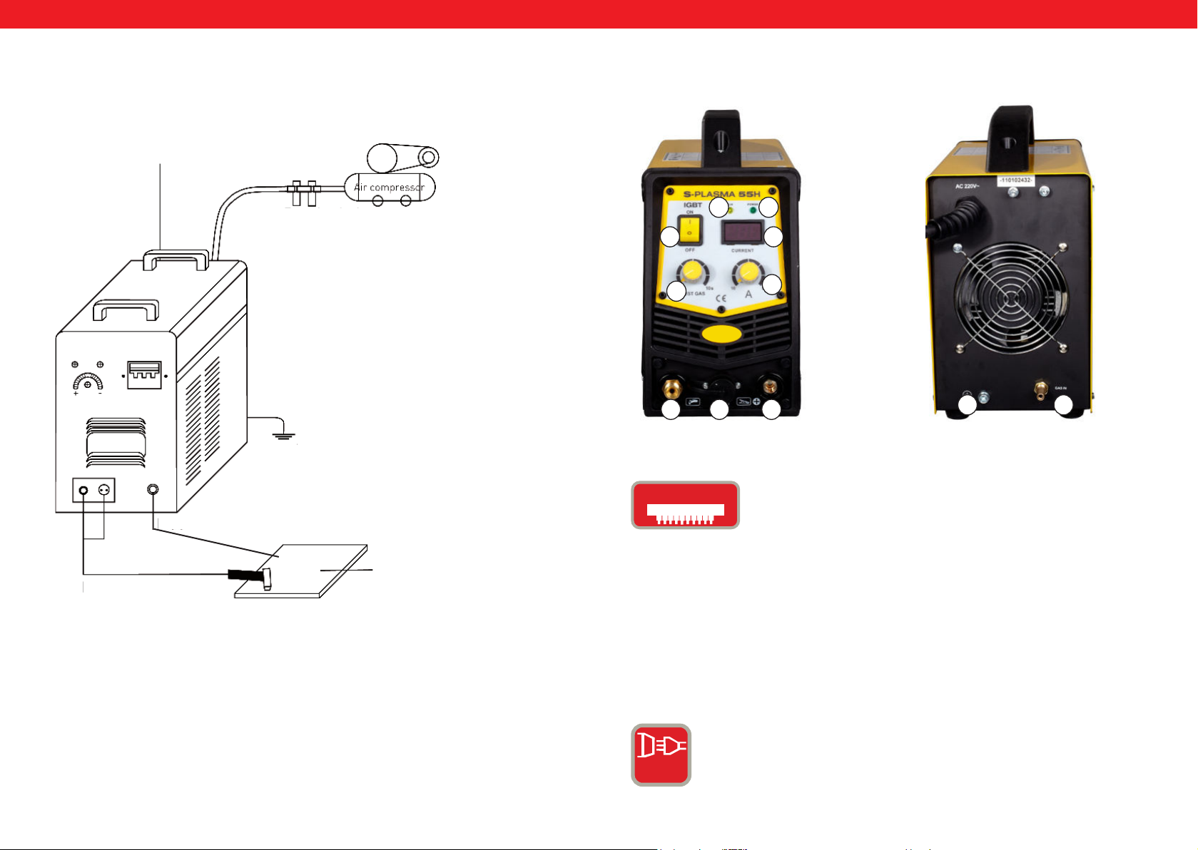
LEGENDE:
0.
On
Off
1.
2.
An- / Ausschalter
Stromregler:
CURRENT = Hauptstrom einstellbar.
Überlastung / Störfall LED:
Bei folgenden zwei Situationen geht die Lampe an:
a) Wenn die Maschine eine Fehlfunktion hat und nicht betrieben
werden kann.
b) Wenn das Schneidgerät die standardmäßige Belastungsdauer
überschreitet, setzt der Schutzmodus ein und die Maschine stellt
ihre Funktion ein. Das heißt, dass das Gerät jetzt ausläuft um die
Temperaturkontrolle wieder herstellen zu können, nachdem
das Gerät überhitzt wurde. Die Maschine kommt aus diesem
Grunde zum Stillstand. Während dieses Vorgangs leuchtet die rote
Warnleuchte an der Frontverkleidung auf. In diesem Fall müssen Sie
nicht den Stromstecker aus der Steckdose entfernen. Zum Abkühlen
der Maschine kann die Lüftung weiter arbeiten um die Kühlung
voranzutreiben. Wenn das rote Licht nicht mehr aueuchtet, ist die
Temperatur nun auf normale Betriebstemperatur gesunken und das
Gerät kann wieder in Betrieb gesetzt werden.
3.
4.
5.+6.
7.
8.
GAS
POWERSANZEIGE = Wenn man die Maschine einschaltet, geht dieses
Licht an.
LED – Display:
Zeigt die aktuelle Amperestärke an.
Anschlüsse für den Plasmabrenner:
Die hohe Energiedichte des Plasmalichtbogens erlaubt eine hohe
Schnittgeschwindigkeit bei gleichzeitig verzugsfreier Schnittqualität.
Es ist kein teures Spezialgas erforderlich, die Verwendung normaler
Druckluft und die problemlose Handhabung sind ein Garant für den
problemlosen Einsatz im Karosserie- Behälter- und Stahlbau, in der
Heizungs- Klima- und Lüftungsbranche sowie im Installations- und
Sanitärbereich.
Massekabelanschluss
GAS / Luftanschluss
AIR
8 9
Rev. 04.04.2022 Rev. 04.04.2022
Page 6
DE
DE
9.
10.
11.
12.
Erdung:
Hinter jedem Schweißgerät bendet sich
eine Schraube und eine Markierung, um
die erforderliche Erdung vorzunehmen. Vor
Bedienung ist es notwendig die Schale des
Schweißgerätes mittels eines Kabels, dessen
Einschnitt nicht kleiner sein darf als 6mm, mit der
Erde zu verbinden, um potentiellen Problemen durch
Entweichung von Elektrizität vorzubeugen.
Zusätzlicher Stromanschluss für den Plasmabrenner Schlauch
POST TIME = Gasnachströmzeit regelbar in Sekundenintervallen.Diese
Regulierung ist wichtig um das geschmolzene Schweißgut nach dem
Schweißvorgang zu kühlen und vor Oxidation zu schützen.
13.
2T/4T = Auswahlschalter
14.
POST FLOW = Mit diesen Knopf können Sie die Gasnachlaufzeit
regeln.
15.
TEST GAS = schützen.
16.
U. V LED = Under Voltage LED. Wenn die Spannung unter 330V fällt,
geht leuchtet diese LED auf
17.
O. V LED = Over Voltage LED. Wenn die Spannung über 420V steigt,
leuchtet diese LED auf.
SWITCH
ROCKER SWITCH = Wenn der Schneider(das Schneidelement ) in
einer nicht selbstxierenden Position justiert ist, halten Sie
den Startknopf am Schneidbrenner gedrückt um mit dem Schneiden
zu beginnen.
Um den Schnitt zu beenden lassen Sie den Knopf los, diese Art vom
18.
GASSHT = Wenn die Maschine keinen oder einen nicht ausreichen-
den Gasuss hat, so leuchtet diese LED auf.
Plasmaschneiden ist geeignet für kurzes Naht schneiden.
Wenn das Schneidelement in der Selbst xierenden Position justiert
ist, dann drücken Sie den Knopf am Schneidbrenner einmal und der
19.
Lichtbogen zündet. Sie können so ununterbrochen Schneiden.
Drücken Sie den Schalter erneut, um mit dem Schneiden aufzuhören,
Diese Art des Plasmaschneiden ist geeignet für langes Naht schneiden.
PHASEN STROMVERLUST = Wenn an das Gerät die 3 StromPhasen nicht angeschlossen sind, man somit nur zwei oder eine Phase
angeschlossen hat, leuchtet diese LED auf und die Maschine wird aufhören zu arbeiten.
20
CNC-Anschulss
10 11
Rev. 04.04.2022 Rev. 04.04.2022
Page 7
DE
DE
Stromkabel
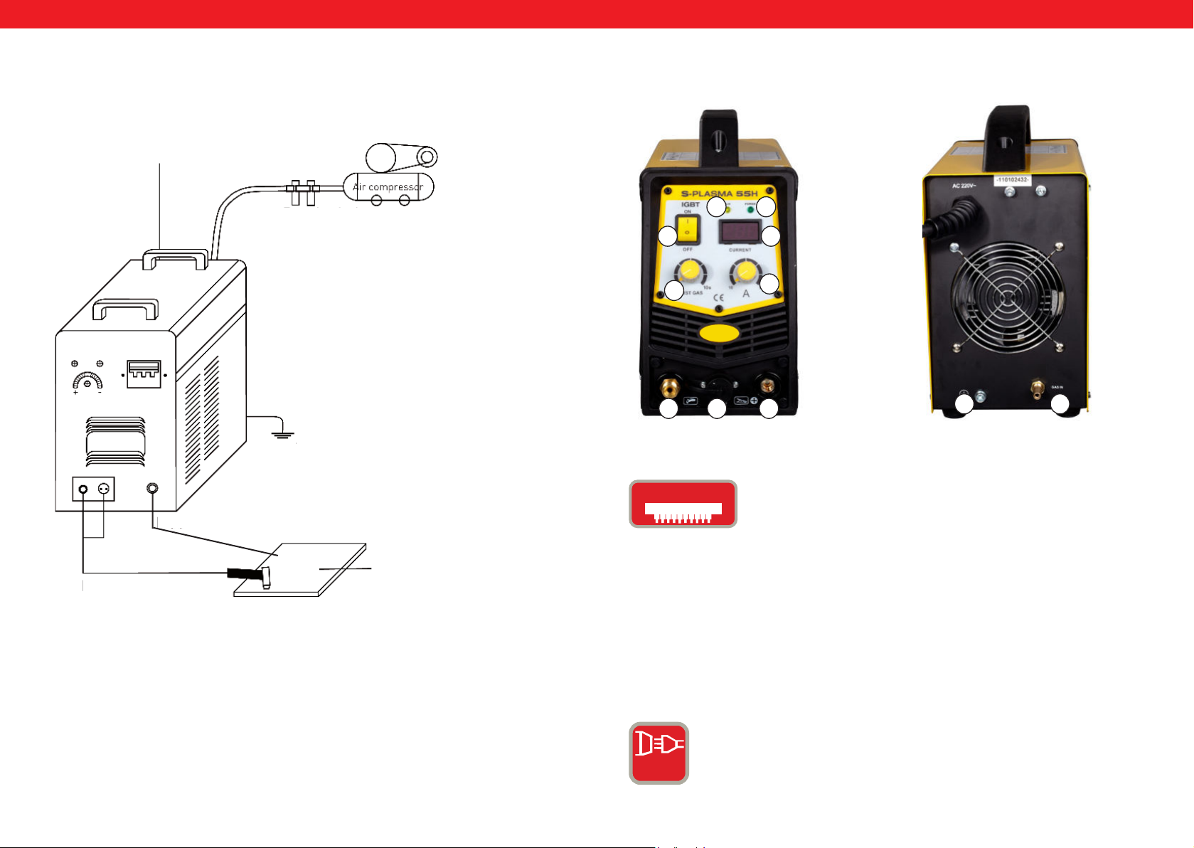
Anschlussschema S-Plasma 55H
Druckminderer
an Kompressor
Gehäuseabsicherung
Luftkompressor
S-PLASMA 55 H
VORDERANSICHT
32
0
11
4
1
567
RÜCKANSICHT
9 8
IGbT
Massekabel
Werkstück
Plasmabrenner
Ein Bipolartransistor mit isolierter Gate-Elektrode
(english Insulated Gate Bipolar Transistor, kurz IGBT)
ist ein Halbleiterbauelement, das zunehmend in der
Leistungselektronik verwendet wird, da es Vorteile des
Bipolartransistors (z.B. gutes Durchlassverhalten, hohe
Sperrspannung, Robustheit beim Schweißgeräten) und Vorteile
eines Feldeffekttransistors (nahezu leistungslose Ansteuerung)
vereinigt. Vorteilhaft ist auch eine gewisse Robustheit
gegenüber Kurzschlüssen, da der IGBT den Laststrom
begrenzt. IGBTs sind eine Weiterentwicklung des vertikalen
Leistungs-MOSFETs.
NORMALSTROM: Das Gerät arbeitet mit einem
1-Phasenanschluss (230V +/- 10%).
1 PH
12 13
Rev. 04.04.2022 Rev. 04.04.2022
Page 8
DE
DE
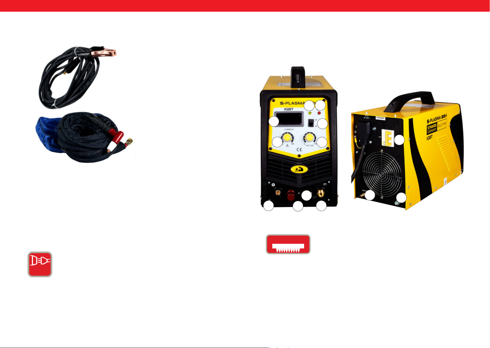
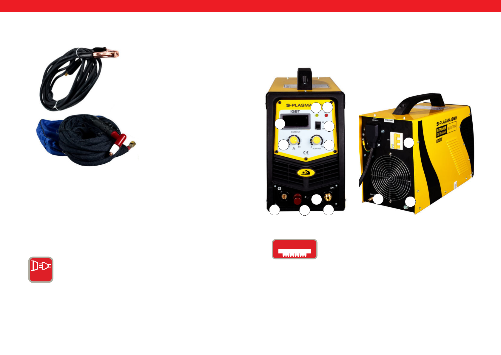
Zubehör bei Plasmaschneidern
1
1. Masseklemme
2. Plasmabrenner
2
S-PLASMA 85H | S-PLASMA 85CNC
VORDERANSICHT
19
2
4
1
12
11
RÜCKANSICHT
0
20
5
20. Nur für das Modell S-PLASMA 85CNC
NETZANSCHLUSS FÜR S-PLASMA 85H / S-PLASMA 85CNC
STARKSTROM = Diese Geräte arbeiten mit einem
3-Phasenanschluss (400V +/- 10%)
6
IGbT
3 PH
14 15
Rev. 04.04.2022 Rev. 04.04.2022
7
Ein Bipolartransistor mit isolierter Gate-Elektrode
(english Insulated Gate Bipolar Transistor, kurz IGBT)
ist ein Halbleiterbauelement, das zunehmend in der
Leistungselektronik verwendet wird, da es Vorteile des
Bipolartransistors (z.B. gutes Durchlassverhalten, hohe
Sperrspannung, Robustheit beim Schweißgeräten) und Vorteile
eines Feldeffekttransistors (nahezu leistungslose Ansteuerung)
vereinigt. Vorteilhaft ist auch eine gewisse Robustheit
gegenüber Kurzschlüssen, da der IGBT den Laststrom
begrenzt. IGBTs sind eine Weiterentwicklung des vertikalen
Leistungs-MOSFETs.
8
9
Page 9
DE
PODŁĄCZENIE CNC
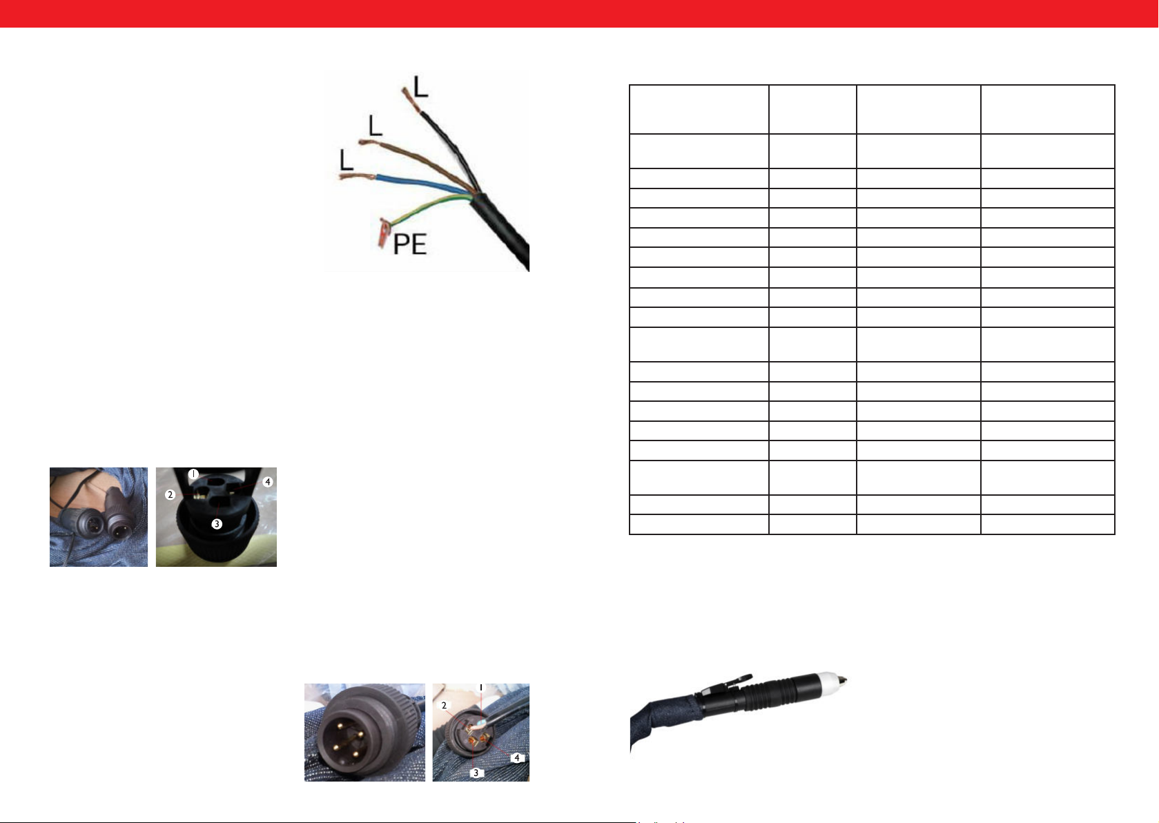
Aby podłączyć przecinarkę do maszyny CNC należy podłączyć dwa piny we
wtyczce: pin 3 oraz pin 4. CNC będzie działać w przypadku gdy maszyna CNC
będzie włączona, w przeciwnym przypadku będzie działało tylko cięcie ręczne.
Pin 1 oraz 2 są podłączone fabrycznie i jest to podłączenie tylko i wyłącznie do
cięcia ręcznego:
DE
Anschluss S-Plasma 85H + 125H / 85CNC + 125CNC
Netzanschlussplan
Die gelb-grüne Ader ist für den Schutzleiteranschluss PE vorgesehen. Die drei Phasen
(schwarz, braun und blau) können beliebig an
L1, L2 und L3 angeschlossen werden. Bitte lassen Sie diese Arbeiten nur von einer qualizierten Elektrofachkraft ausführen lassen).
Achtung!!!
Schweißgeräte mit Starkstromanschluss dürfen nur durch eine Elektrofachkraft angeschlossen werden!
CNC ANSCHLUSS S-PLASMA 125CNC
Um den Plasmaschneider an die CNC-Maschine anzuschließen, müssen die zwei Stöpsel in dem Stecker verbunden werden.
Stöpsel 4: Positiver Pol
Stöpsel 2: Negativer Pol
Technische Details
S-Plasma
55H
Eingangsspannung 230V
1-Phase
Frequenz 50Hz 50Hz 50Hz
Eingangsstrom 16A 19 A 20 A
Leerlaufspannung 230 V 280 V 300 V
Gehäuseschutzgrad IP20S IP20S IP21S
Isolationsklasse F F F
Überspannungsschutz ja ja ja
Kühlung Lüfter Lüfter Lüfter
Magnetventil ja ja ja
Einschaltdauer ED
bei max. A
A bei 100% duty cycle
Schneidstrom 10-55 A 20-85 A 10-125 A
Zündung Kontakt Non-Kontakt Non-Kontakt
Schnitttiefe 17 mm 27 mm 34 mm
Schnittbreite 1 mm 1,2 mm 1,4 mm
Kompressor Anschluss 4,5 bar,30-100
Gewicht (netto) 9.4 kg 19,5 kg 30 kg
Abmessung L/B/H (mm) 530/380/380 660/370/450 660/370/450
60% 60% 60%
42,6 65,8 96,8
1/min.
S-Plasma 85H
und
S-Plasma 85CNC*
400V
3-Phasen
5,5 bar,
175 l/min.
S-Plasma 125H
und
S-Plasma 125CNC*
400V
3-Phasen
7 bar
250 l/min
* Achtung: Die Modelle S-Plasma 85CNC sowie S-Plasma 125CNC sind mit einem
zusätzlichen CNC-Anschluss ausgestattet. Außerdem sind diese zwei Plasmaschneidermodelle mit einem einfachen Brenner ausgestattet.:
CNC ANSCHLUSS S-PLASMA 85CNC
Um den Plasmaschneider an die CNC-Maschine anzuschließen, müssen die zwei Stöpsel in dem Stecker verbunden werden: Pin 3 und Pin 4. Die CNC-Funktion funktioniert unter der Voraussetzung, dass die CNC-Maschine eingeschaltet ist. Andererseits,
für den Fall dass die CNC-Maschine ausgeschaltet ist, funktioniert nur ein manuelles
Schneiden.
Pin 3: Positiver Pol
Pin 4: Negativer Pol
16 17
Rev. 04.04.2022 Rev. 04.04.2022
Page 10
DE
DE
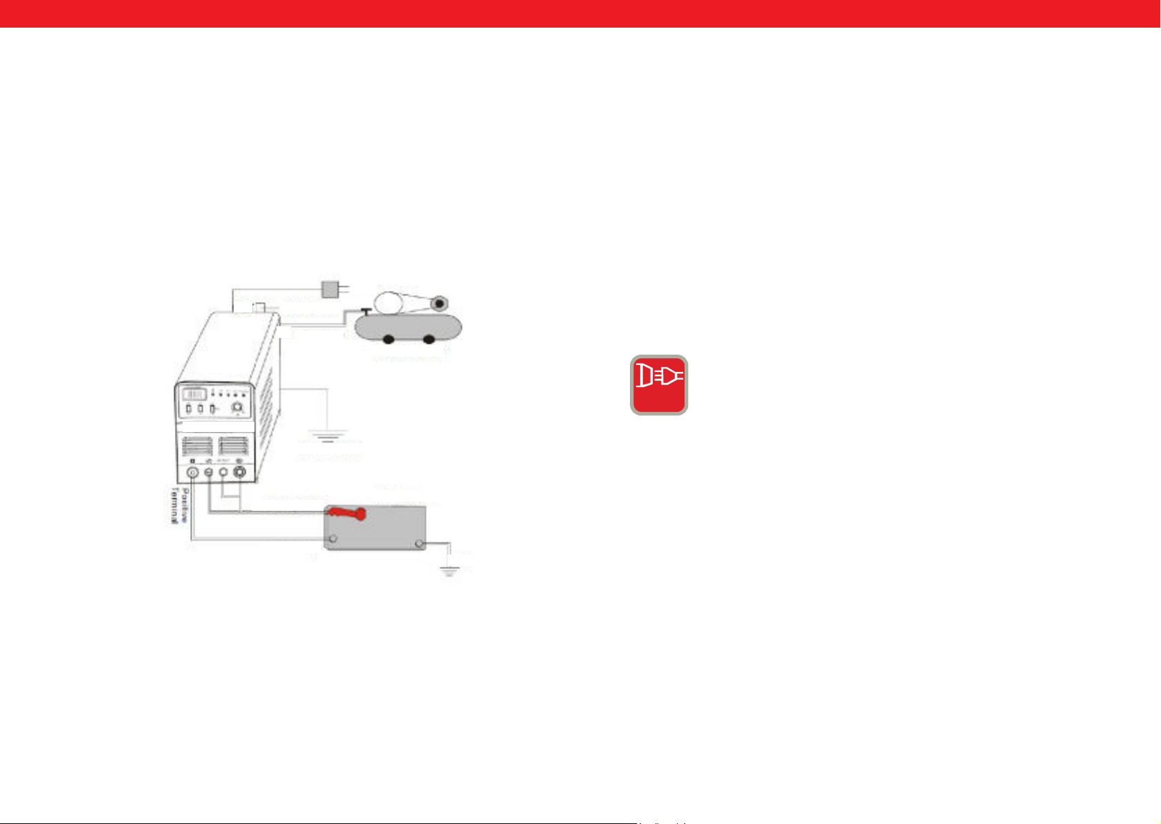
Installation
1.Jeder Plasmaschneider ist mit einem Stromkabel ausgestattet und entsprechend
der Eingangsspannung des Plasamschneiders, muss es mit der entsprechenden
Stromversorgung verbunden werden.
2.Das Stromkabel sollte gut an den Ein-Schalter oder Steckverbinder angeschlossen werden, um Oxidation zu verhindern. Wenn möglich, prüfen Sie mit
einem Messgerät, ob die Stromspannung im erforderlichen Bereich ist.
Anschluss von Zuleitungen (Installations Skizze)
400V
OUT
Luftdruckregulierung
IN
Luftschlauch
Luftkompressor
S-Plasma 125H
Gehäuseerdung
Bedienung
Schalten Sie den Einschalter auf dem hinteren Paneelfeld ein, die Kontrollleuchte
geht an und der aktuelle Strom wird angezeigt.
Stellen Sie den Gasdruck entsprechen den Anforderungen ein und öffnen Sie das
Kompressionsventil.
Drücken Sie den Steuerungsknopf auf dem Schneidbrenner, dann arbeitet das
Ventil, Sie können den Lichtbogen hören und sehen.
Stellen Sie je nach Dicke des Werkstücks den Schneidstrom ein.
Bringen Sie die Kupferdüse des Schneidbrenners auf das Werkstück auf (Kupferdüse bei Lichtbogen etwa 2 mm vom Werkstück entfernt) drücken Sie die Taste
auf dem Brenner, bis der Lichtbogen gestartet wird, dann heben Sie die Schneiddüse etwas an, etwa 1mm vom Werkstück und beginnen Sie zu schneiden.
3 PH
STARKSTROM = Diese Geräte arbeiten mit einem
3-Phasenanschluss (400V +/- 10%)
Schneidbrenner
Werkstück
Masseklemme
Erdung
18 19
Rev. 04.04.2022 Rev. 04.04.2022
Page 11
DE
DE
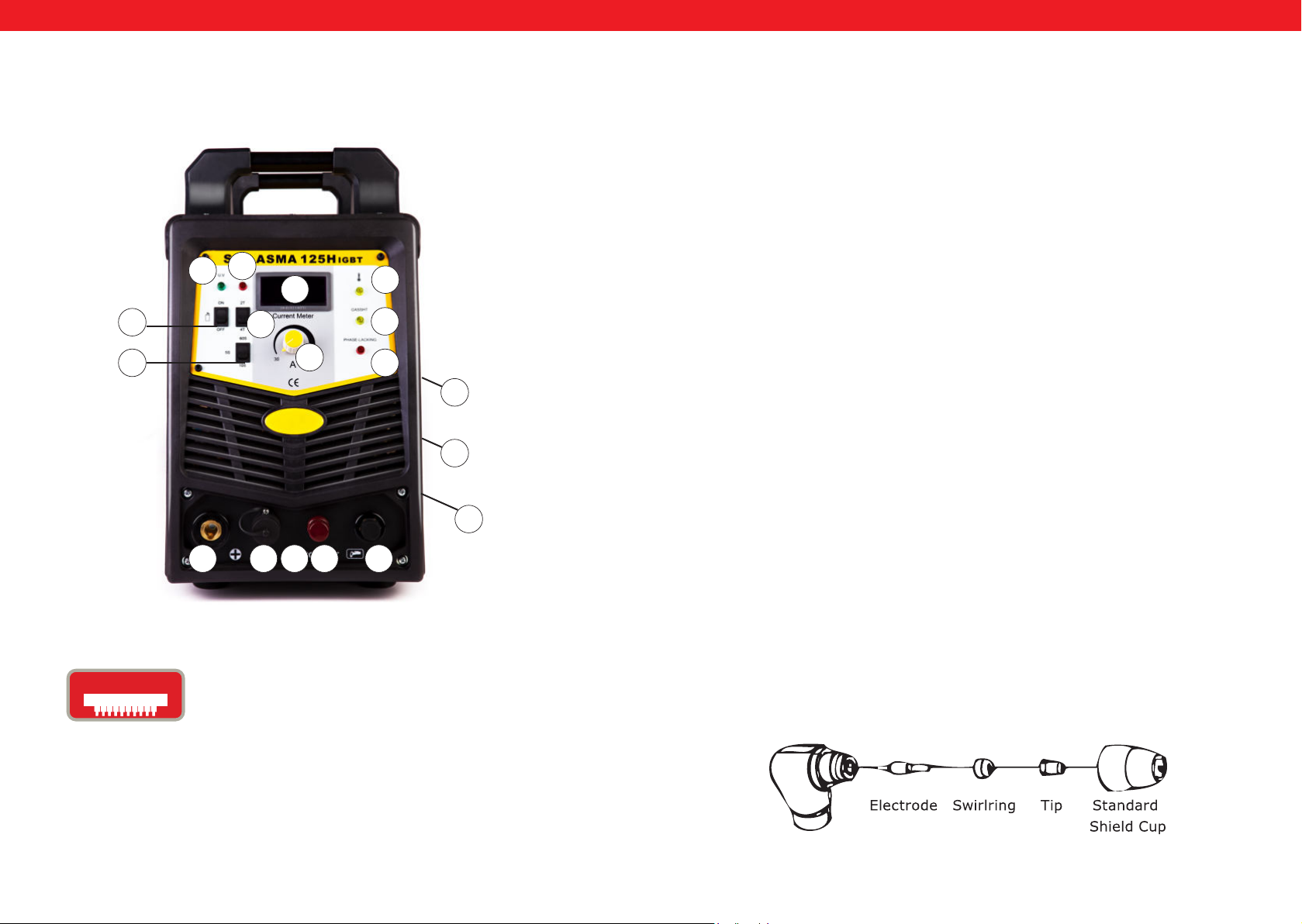
S-PLASMA 125H | S-PLASMA 125CNC
17
16
4
15
14
7
13
1
10 6 5
20
2
18
19
INSTANDSETZUNG
A. Entpackung
Entpacken Sie alle Sachen aus der Verpackung und versichern Sie sich, dass Sie alle Gegenstände, die auf der Verpackungsliste aufgelistet sind, erhalten haben.
B. Arbeitsumgebung
Stellen Sie sicher, dass der Arbeitsbereich gut belüftet ist. Das Gerät wird durch einen
Axiallüfter gekühlt, der einen Luftuss durch das hintere Bedienteil über der Elektronik
bereitstellt.
(Hinweis! Die Verkleidung muss so installiert werden, dass sich die Entlüftungslöcher
näher an der Vorderseite des Gerätes benden) Lassen Sie mindestens ca. 15 cm am
Vorderteil und 15 cm an beiden Seiten zur Säuberung frei. Wenn das Gerät ohne ausreichende Kühlung bedient wird, reduziert sich die Einschaltdauer stark.
C. Kabeleingangsverbindung
Jedes Gerät verfügt über ein Hauptstromkabel, das dafür zuständig ist, die Stromstärke
0
und Spannung für dieses Gerät herzustellen. Wenn das Gerät mit Strom verbunden ist,
der die benötigte Spannung überschreitet, oder eine falsche Phase eingestellt ist, kann
dies das Gerät schwer schädigen. Dies wird nicht innerhalb der Gewährleistungsbedingungen des Gerätes berücksichtigt, sondern geht auf Ihr eigenes Verschulden zurück.
9
D. Fackelverbindung
Verbinden Sie die Fackel mit dem Invertierer indem Sie das Luftröhrchen, das am Ende
8
der Fackel befestigt ist, an das Fackelverbindungsstück, das am Vorderteil der Maschine
angebracht ist, hereindrehen. Sichern Sie die Konstruktion noch einmal durch leichtes
Festziehen mit einem Schraubenschlüssel. Ziehen Sie es nicht zu straff zu.
PISTOLENAUFBAU
20. Nur für das Modell S-PLASMA 125CNC
IGbT
20 21
Ein Bipolartransistor mit isolierter Gate-Elektrode
(english Insulated Gate Bipolar Transistor, kurz IGBT)
ist ein Halbleiterbauelement, das zunehmend in der
Leistungselektronik verwendet wird, da es Vorteile des
Bipolartransistors (z.B. gutes Durchlassverhalten, hohe
Sperrspannung, Robustheit beim Schweißgeräten) und Vorteile
eines Feldeffekttransistors (nahezu leistungslose Ansteuerung)
vereinigt. Vorteilhaft ist auch eine gewisse Robustheit
gegenüber Kurzschlüssen, da der IGBT den Laststrom
begrenzt. IGBTs sind eine Weiterentwicklung des vertikalen
Leistungs-MOSFETs.
Rev. 04.04.2022 Rev. 04.04.2022
Page 12

DE DE
A. Vorgang des Pistolenlaufbaus
Stellen Sie die Pistole mit der Schutzkappe nach oben zeigend auf, und drehen
Sie die Schutzkappe, von der Pistole ab. (Schutzkappe hält die Spitze, den Keramikdrehungsring, und die Elektrode zusammen). Entfernen Sie die Spitze, den Keramikdrehungsring und die Elektrode. Bauen Sie die Elektrode, den Keramikdrehungsring und
die Spitze wieder zusammen. Ersetzen Sie abgenutzte Teile, wenn es notwendig ist. Bringen Sie die Schutzkappe an dem Kopf der Pistole an, und ziehen Sie diese mit der Hand
fest, bis sie straff sitzt. Wenn bei diesem Vorgang ein Widerstand bemerkt wird, prüfen
Sie die Gewinde und die Anordnung der Einzelteile, bevor Sie mit der Arbeit beginnen.
Hinweis
Bei einigen Pistolen, die keine umschaltbaren Elektroden haben, ist es notwendig die
Elektrode noch zusätzlich, durch das Anwenden einer Kneifzange festzuziehen um somit eine verlässliche elektrische Verbindung zu gewährleisten.
NUTZUNG
A. Der Anfang
Schalten Sie den Stromschalter auf die Stellung “ON”. Positionieren Sie sich so, dass Sie
den Luftdruck problemlos vom Gerät ablesen können. Drücken Sie den Pistolenschalter (Luft wird aus der Pistole ausströmen), stellen Sie das Luftregelventil auf ca. 6–7
(Bar) und lassen Sie den Pistolenschalter wieder los.
Hinweis
Der Luftdruck hat einen allgemeinen Akzeptanzbereichvon 5 bis 8 Bar. Sie können wie
gewünscht Versuche durchführen, aber es ist Vorsicht geboten, den Luftdruck nicht so
sehr herabzusenken, weil so eine Schädigung des Verbrauchsmaterials auftreten kann.
Sichern Sie die Erdungsklemme am Arbeitsgegenstand. Verbinden Sie die Klemme mit
dem Hauptteil des Arbeitsgegenstandes, nicht dem Teil, das wieder abgenommen wird.
B. Schneiden
1. Drag- Schneiden
Halten Sie die Pistolenspitze seicht über den Arbeitsgegenstand, drücken Sie den Pistolenschalter und bewegen Sie die Pistolenspitze bis es zum Kontakt mit dem Arbeitsgegenstand kommt und der Schneidebogen sich festgesetzt hat. Nachdem der
Schneidebogen generiert wurde, bewegen Sie nun die Pistole in die gewünschte Richtung, wobei die Pistolenspitze stets leicht angewinkelt ist und der Kontakt mit dem Arbeitsgegenstand beibehalten werden sollte. Diese Arbeitsmethode wird Dragschneiden
genannt. Meiden Sie zu schnelle Bewegungen. Ein Anzeichen dafür sind Funken, die von
der Oberseite des Arbeitsgegenstandes absprühen. Bewegen Sie die Pistole gerade so
schnell, dass die Funkenansammlung an der Unterseite des Arbeitsgegenstandes konzentriert und vergewissern sie sich, dass das Material komplett durchtrennt ist, bevor
sie fortfahren. Stellen Sie die drag Geschwindigkeit wie erforderlich ein.
2. Wöchentliche Maßnahmen
Überprüfen Sie, ob die Lüftung einwandfrei funktioniert Blasen oder saugen Sie Staub
oder Dreck von der ganzen Maschine, inklusive des Luftlter ab.
3. Distanzschneiden
In einigen Fällen kann es vorteilhaft sein, mit der Pistolenspitze, die ca. 1/16“ to 1/8”
über dem Arbeitsgegenstand gehalten werden sollte, zu schneiden, um
Material zu reduzieren, welches wieder zurück in die Spitze geblasen wird und um die
Durchdringung von dicken Einschnitten im Material zu maximieren. Distanz-schneiden sollte eingesetzt werden, wenn Durchdringungsschneiden, oder Furchenarbeiten
durchgeführt werden. Sie können außerdem die Distanz” Arbeitstechnik anwenden,
wenn Sie Blech schneiden, um das Risiko von zurückspritzenden Materialien, welche die
Spitze beschädigen könnten, zu minimieren.
4. Durchbohren
Zum Durchbohren, setzen Sie die Spitze ca. 3,2 mm über dem Arbeitsgegenstand an.
Halten Sie die Pistole leicht angewinkelt, um die Funken von der Pistolenspitze und
von Ihnen weg zurichten. Betätigen Sie den Hauptbogen und senken Sie die Spitze der
Pistole bis der Hauptschneidebogen ausfährt und die Funkenbildung beginnt. Starten
Sie mit der Durchbohrung an einem nicht mehr verwendbaren Versuchsgegenstand und
beginnen Sie,wenn dieses ohne Probleme funktioniert,mit dem Durchbohren an der
vorher denierten Schneidelinie.
WARTUNG
Überprüfen Sie die Pistole hinsichtlich Abnutzungsschäden, Rissen oder freigelegten
Kabelstücken. Ersetzen oder reparieren Sie jene vor Gebrauch des Gerätes. Eine stark
abgenutzte Pistolenspitze/düse trägt zur Verminderung der
Geschwindigkeit, Spannungsabfall und krummen Durchtrennung bei. Ein Indiz
für eine stark abgenutzte Pistolenspitze/-düse ist eine verlängerte oder übergroße Düsenöffnung. Das Äußere der Elektrode darf nicht mehr als 3,2mm vertieft sein. Ersetzen
Sie diese, wenn sie abgenutzter ist als die vorgegebene Abmessung angibt. Wenn die
Schutzkappe nicht einfach zu befestigen ist, überprüfen sie die Gewinde.
Achtung: Achten Sie beim Wechseln der Düse und Elektrode unbedingt immer darauf, dass das Gerät ausgeschaltet ist.
Prüfung
1. Das Gehäuse sollte immer sicher geerdet sein.
2. Prüfen Sie, ob alle Anschlüsse fest verbunden sind.
3. Prüfen Sie, ob das Stromkabel mit der richtigen Spannung versorgt wird.
4. Achten Sie darauf, dass Kabel und Schläuchen nicht beschädigt oder abgenutzt sind.
22 23
Rev. 04.04.2022 Rev. 04.04.2022
Page 13

MODE D`EMPLOI
FR
Ce mode d‘emploi comprend les descriptions, les instructions d‘emploi et les processus
d‘entretien fondamentaux pour les découpeurs plasma S-Plasma 85H/125H Stamos
Germany. Étudiez ces instructions d‘emploi en détail. Une compréhension complète
des caractéristiques et des capacités de l‘appareil en garantit une application correcte.
ATTENTION
• Travaillez en sécurité. Protégez vous ainsi que les tierces personnes de tout danger.
Lisez attentivement en respectez les consignes de sécurité.
• La mise en fonctionnement, l’utilisation ainsi que l’entretient de l’appareil doivent
être exclusivement menés par des personnes qualiées.
• Lorsque vous utilisez l’appareil, tenez à distance du lieu de travail toute personne,
en particulier les enfants.
La DECOUPE peut provoquer des feux ou des explosions.
S-PLASMA 55H | S-PLASMA 85H
S-PLASMA 125H | S-PLASMA 85CNC
S-PLASMA 125CNC
Des étincelles et des pièces de métal incandescentes sont projetées lors du soudage.
La pièce, les projections et certaines parties de l’appareil peuvent entraîner incendies
et brûlures. Assurez-vous avant emploi que le lieu de travail est indiqué pour travailler
en toute sécurité.
• Tout objet inammable doit être tenu à une distance minimale de 10,7m de
l’appareil.
• Si ce n’est pas possible, couvrez ces objets méticuleusement avec du matériel
prévu à cet effet.
• Ne procédez à aucun e découpe dans un lieu où les étincelles peuvent rencontrer
un objet inammable.
• Protégez les tierces personnes ainsi que vous-même des étincelles et projections
de métal incandescent.
• Soyez attentif, les étincelles et projections de métal chaud peuvent facilement
s’introduire dans de petites ssures et ouvertures adjacentes au champ de travail
lors du découpage.
• Faites attention aux incendies et conservez toujours un extincteur à votre portée.
• Faites attention à la surface sur laquelle vous travaillez car un feu peut se déclarer
sur le côté opposé et non visible de cette même surface de travail
expondo.de
Rev. 04.04.2022 Rev. 04.04.2022
25
Page 14

FR
FR
Ne découpez pas des récipients fermés tels que des réservoirs ou
des fûts
Branchez le cordon d’alimentation dans une prise électrique à proximité du champ de
travail, ceci an d’éviter que le cordon ne soit déroulé dans toute la pièce et qu’il ne
puisse être en contact avec une surface pouvant provoquer un choc électrique, des
étincelles ou encore un incendie.
• N‘utilisez pas le découpeur plasma pour décongeler des canalisations gelées.
• Ne découpez jamais des récipients susceptibles de contenir des matières inam-
mables. Les récipients doivent être auparavant vidés et soigneusement nettoyés.
• Ne découpez pas dans un environnement contenant des particules de poussières
ou des vapeurs explosives.
• Ne découpez pas des cylindres, des récipients ou des conduits sous pression.
• Ne découpez pas des récipients ayant contenu des substances inammables.
• Portez des vêtements de protection ne présentant aucune trace d’huile ou de tout
autre matière inammable comme par exemple des gants en cuir, une chemise épaisse, un pantalon sans revers, des chaussures de sécurité ou encore un masque de
protection.
• Ne travaillez pas sur des surfaces inammables.
• Séparez-vous de tout objet inammable (briquet ou allumettes par exemple) avant
de commencer à souder.
• Respectez les conditions de travail appropriées à des travaux de découpage et assurez-vous de toujours avoir un extincteur à votre portée. Le contact avec des objets chargés électriquement peut entraîner des chocs électriques dangereux et des
brûlures graves. La torche et le circuit de soudage sont électriquement chargés dès
que l’appareil est sous tension. Le circuit électronique d’entrée et le circuit interne
de l’appareil sont également sous tension dès que l’appareil est allumé.
ou nettoyage de la torche.
• Mettre l’appareil hors-tension avant de l’installer ou isolez-vous de la pièce d’ouvrage
et du sol en utilisant un tapis d’isolation sec.
• Assurez-vous que le câble de mise à terre du cordon d’alimentation soit correctement relié à la terre ou que le cordon d’alimentation soit bien branché à une prise
électrique équipée d’une prise terre.
• Vériez toujours le raccordement à la terre.
• Procédez au raccordement à la terre avant d’effectuer la connexion d’entrée.
• Assurez-vous régulièrement que le cordon d’alimentation ne soit pas endommagé
ou dénudé. Remplacez-le s’il est endommagé. Un cordon dénudé peut entraîner la
mort.
• Débranchez l’appareil lorsque vous ne l’utilisez pas.
• Inspectez régulièrement le câble et remplacez-le immédiatement si vous notez des
traces d’usure importantes ou des endommagements.
• N’enroulez pas le câble autour de vous.
• Connectez soigneusement la pièce d’ouvrage à la terre.
• N’utilisez que des équipements en bon état.
• Réparez ou remplacez immédiatement toute pièce endommagée de l’appareil.
• Portez une sangle de sécurité si vous travaillez en hauteur.
• Conservez tous les éléments et protections au même endroit.
• Tenez-vous à distance de la pointe de la torche et de l’arc lorsque vous appuyez sur
la gâchette.
• Fixez soigneusement le câble de masse sur une partie métallique de la pièce
d’ouvrage ou sur la surface de travail aussi près du poste à souder que cela semble
approprié.
• Isolez la pince crocodile lorsqu’elle n’est pas connectée à la pièce d’ouvrage an
d’éviter tout contact avec un métal.
La découpe plasma nécessite un haut voltage an d‘amorcer l‘arc, et comme en soudage, selon la règle, celui-ci nécessite 200 à 400 Volt dc. Mais l‘appareil dispose d‘un
pistolet équipé d‘un verrouillage de sécurité qui met l‘appareil hors circuit lorsque la
protection s‘est détachée ou que la pointe de l‘électrode est rentrée en contact avec
l‘intérieur de la buse. Une mauvaise installation de l’appareil et de sa mise à la terre
présentent représente un grand danger.
UN CHOC ELECTRIQUE PEUT ENTRAINER LA MORT.
• Ne touchez jamais les parties sous tension.
• Portez des gants et protections corporelles sèches, isolantes et en parfait état.
• Assurez-vous d’être vous-même bien isolé de la pièce d’ouvrage et du sol au moyen
de tapis isolants et de panneaux de protections secs.
• Ne touchez en aucun cas la torche lorsque celle-ci est en contact avec la pièce
d’ouvrage ou le sol.
• Mettre l’appareil hors-tension avant de procéder à toute modication, vérication
26 27
Rev. 04.04.2022 Rev. 04.04.2022
Une tension importante persiste après avoir débranché le cordon
d’alimentation de la source d’alimentation.
Éteignez l’appareil, séparez le cordon d’alimentation, vériez que la tension du condensateur d’entrée soit proche du zéro avant de toucher les pièces de l’appareil. Contrôlez
le condensateur en suivant les indications du chapitre maintenance avant de toucher
les pièces de l’appareil.
Un CHOC ELECTRIQUE peut être mortel.
Le pistolet peut entraîner des chocs électriques ainsi que des projections lorsqu’il est
sous tension. Portez toujours un masque de protection et une chemise manches longues lorsque vous utilisez la torche.
Page 15
FR
FR
Les PROJECTIONS peuvent engendrer des blessures graves.
Des étincelles et du métal incandescent sont projetées lors la soudure.
Les ÉTINCELLES peuvent entraîner des blessures.
• Portez un masque de protection ou des lunettes de sécurité avec protection latérale.
• Portez des protections appropriées an de protéger la peau.
• Portez des protections pour les oreilles résistantes au feu an d’éviter que des
étincelles ne s’y introduisent.
• L’arc de soudage produit d’intenses rayons (ultraviolets et infrarouge) visibles et
invisibles pouvant brûler la peau et les yeux.
Les RAYONNEMENTS DE L‘ARC peuvent brûler les yeux et la peau.
• Portez une protection pour le visage (casque ou masque) avec
• une teinte approprié an de ltrer les rayons et ainsi protéger les yeux et le visage.
• Les normes de sécurité suggèrent la teinte n°9 (la teinte n°8 minimum) pour tout
exercice de soudure ayant un ampérage inférieur à 300 ampères. Des ltres un peu
moins élevés peuvent être utilisés lorsque l’arc est dissimulé par l’objet de travail.
• Portez des lunettes de protection certiées avec revêtement latéral sous votre
casque ou votre masque.
• Utilisez des écrans de protection ou des séparations an de protéger les tierces
personnes des étincelles et de la lumière aveuglante créées par l’arc ; Veillez à ce que
les tierces personnes ne regardent pas l’arc.
• Portez des vêtements résistants et ignifugés (en cuir, coton ou laine épaisse) et des
chaussures de sécurité appropriées.
rayon du faisceau de plasma.
Indication! Cette machine est conçue pour utiliser uniquement l‘air comprimé en tant
que „gaz“.
Régulation du courant
Le dispositif anti surtension protège l’appareil jusqu’aux valeurs inscrites sur la che
technique.
Protection anti surchauffe
Le dispositif anti surchauffe se met en place lorsque l’appareil dépasse son facteur de
marche. L’appareil sera alors stoppé.
Facteur de marche
Le facteur de marche est le rapport exprimé en pourcentage du temps de fonctionnement continu de l’appareil (mesuré en minutes) sur une période de 10min (correspondant à 100%) dans des conditions de température normales et à ampérage maximal.
Par exemple, si un appareil a un facteur de marche de 60%, cela signie qu’il pourra
être utilisé pendant 6 minutes (60% de 10 min = 60% x 10 = 6min) à ampérage maximal
et température normale avant de se mettre en surchauffe. Si les valeurs du facteur de
marche sont dépassées, la fonction surchauffe sera en effet activée et l’appareil sera
donc arrêté jusqu’à ce qu’il ait refroidi à une température normale. Le dépassement des
valeurs du facteur de marche peut entraîner de sérieux dommages à l’appareil.
PLASMA
Explications générales sur le Plasma: Les découpeurs plasma fonctionnent avec du gaz,
comme l‘air par exemple, mis sous pression et apporté par un petit tuyau. Au milieu
de ce canal, juste au-dessus de la buse, se trouve une électrode chargée négativement.
Le diffuseur fait tourner le plasma aussi vite que possible. Lorsque l‘électrode négative
est alimentée en énergie et que la pointe de la buse est en contact avec le métal, un
circuit se forme. Une puissante étincelle est alors générée entre l‘électrode et le métal.
Alors que le gaz entrant s‘écoule à travers le tuyau, la chaleur de l‘étincelle chauffe le
gaz jusqu‘à ce qu‘il atteigne le quatrième état. Cette réaction provoque un courant de
plasma d‘à peu près 16 649 ° C ou plus, qui se déplace à 6 096 m/s et peut réduire le
métal à l‘état de vapeur et de sécrétions fondues. Le plasma lui-même conduit le courant électrique. Le circuit de travail qui fait naître l‘arc est continu tant que l‘électrode
est alimentée en courant et que le plasma reste en contact avec le métal à travailler.
La buse de découpe présente un deuxième groupe de canaux. Ces canaux libèrent un
ux constant de gaz de protection. La pression exercée par ce ux de gaz contrôle le
28 29
Rev. 04.04.2022 Rev. 04.04.2022
LÉGENDE:
0.
On
Off
1.
Bouton marche/arrêt
Régulateur de courant:
COURANT= Courant principal ajustable.
Page 16
FR
FR
2.
Indicateur de surcharge / incident:
L‘indicateur s‘allume dans les deux situations suivantes:
a) Lorsque la machine est en panne.
b) Lorsque l‘appareil dépasse la limite du facteur de marche, le mode
de protection s‘active et la machine s‘arrête. C‘est-à-dire que l‘appareil
n‘est plus en marche an de rétablir le contrôle de la température après
une surchauffe.
La machine est en veille pour cette raison. Durant ce processus, le signal
d‘alarme rouge s‘active sur l‘avant de l‘appareil. Ne débranchez pas
l’appareil dans ce cas. Le ventilateur pourra ainsi continuer le processus
refroidissement. La température nécessaire à un bon fonctionnement
sera atteinte lorsque le signal rouge s‘éteindra. Vous pourrez à nouveau
utiliser l‘appareil.
3.
INDICATEUR DE MISE EN MARCHE = L’indicateur s’allume lorsque
l’appareil est sous tension.
4.
Indicateur LED:
Afche l’intensité (A) actuelle.
5.+6.
Raccordements pour la torche plasma:
La haute densité d’énergie de l’arc électrique plasma permet à la
fois une découpe rapide et de qualité sans aucune bavure. Il n’est
pas nécessaire d’avoir un gaz spécique et onéreux. L’utilisation d’air
comprimé basique et un bon usage de l’appareil vous permettent
de travailler sans problèmes dans les domaines de la carrosserie, du
chauffage, de la climatisation, de la ventilation, de la plomberie ou dans
la construction de réservoirs et la construction métallique.
7.
Raccordement câble de masse
30 31
Rev. 04.04.2022 Rev. 04.04.2022
8.
9.
10.
11.
12.
GAS
AIR
SWITCH
GAZ/raccordement pour l’air
Raccordement d‘électricité supplémentaire pour le
tuyau de la torche plasma
PRISE DE TERRE:
Derrière chaque machine à souder se
trouvent une vis et une marque pour effectuer
l’indispensable mise à la terre.
Avant l’utilisation, il est nécessaire de relier la
machine à souder à la terre à l’aide d’un câble
dont l’encoche ne doit pas être plus petite que
6mm, ceci an de prévenir d’éventuels problèmes lors
d’une fuite de courant.
PTEMPS DE POST-GAZ= Le temps de post-gaz peut être réglé entre 1
et 10 secondes. Ce réglage est important, pour permettre à la matière
à souder fondue de refroidir après le processus de soudure et pour la
protéger de l’oxydation.
ROCKER SWITCH = Lorsque le découpeur (l‘élément de coupe) est
ajusté dans une position xe, appuyez sur le bouton marche du chalumeau pour commencer à couper. Pour terminer l‘opération, lâchez le
bouton. Ce type de découpage plasma est approprié pour des coupes
courtes. Lorsque le découpeur est ajusté dans la position xe, appuyez
une fois sur le bouton du chalumeau et l‘arc électrique s‘allume. De
cette manière vous pouvez faire des découpes sans vous arrêter. Appuyez de nouveau sur le bouton pour arrêter la découpe. Ce type de
découpage plasma est approprié pour des découpes plus longues.
Page 17
FR
FR
13.
14.
15.
16.
17.
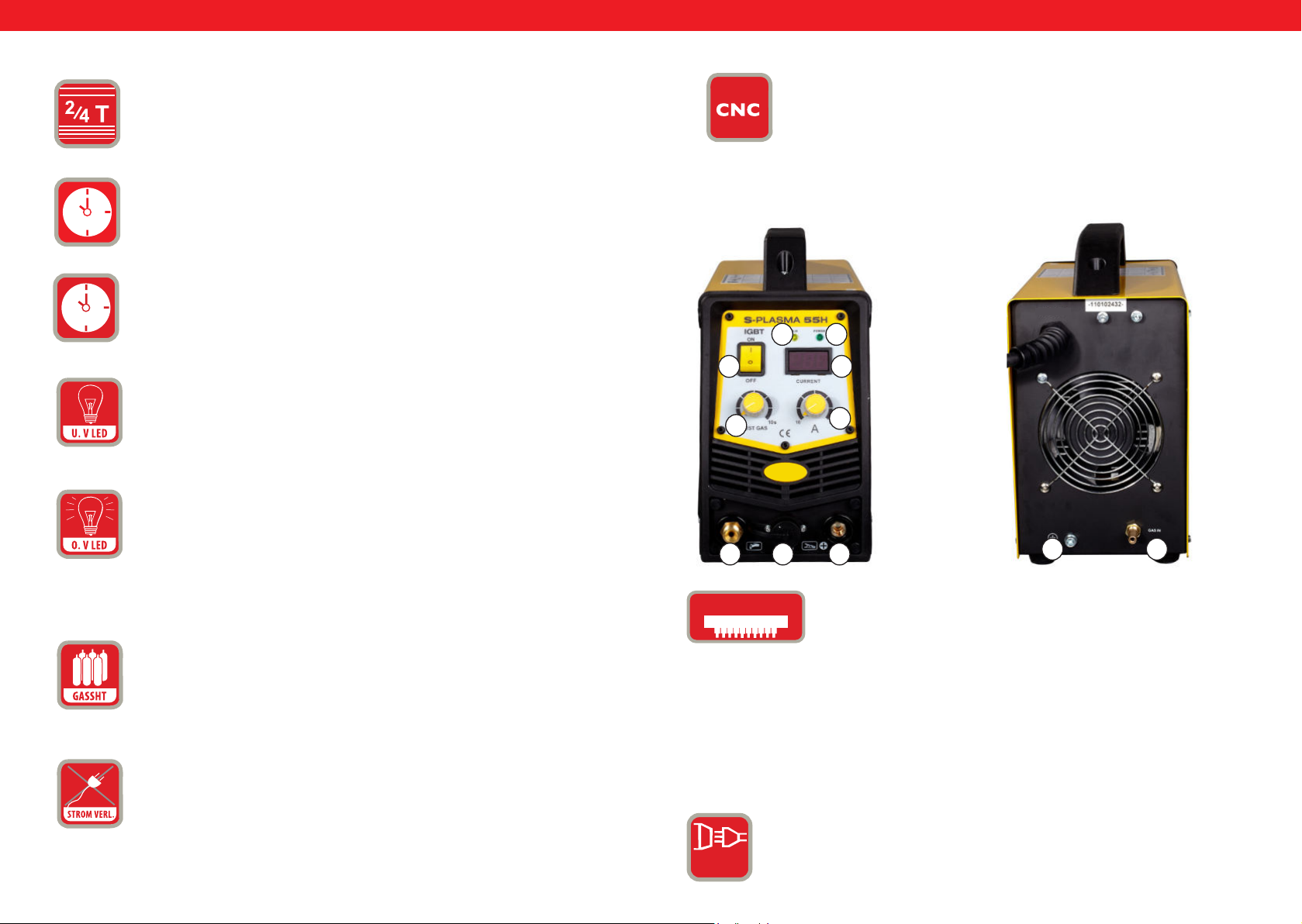
2T/4T = Interrupteur de sélection
POST FLOW = avec ce bouton, vous pouvez régler la durée du temps
de post gaz.
TEST GAZ = protéger.
U.V LED = Under Voltage LED, sous tension. Si la tension tombe à
moins de 330V, la LED s‘allume
O.V LED = Over voltage LED, surtension. Si la tension dépasse les
420V, la LED s‘allume.
20
Connecteur pour CNC
S-PLASMA 55 H
FACE AVANT
0
11
FACE ARRIÈRE
32
4
1
567
9 8
18.
IGbT
Le transistor bipolaire à grille isolée (de l‘anglais
Insulated Gate Bipolar Transistor - IGBT) est un dispositif
semiconducteur qui est de plus en plus utilisé de plus en plus
GASSHT = Si l‘appareil ne reçoit plus ou peu de
ux de gaz, la LED s‘allume.
dans l‘électronique de puissance, car il combine les avantages
du transistor bipolaire (par exemple: grande simplicité de
commande, haute tension de blocage, robustesse des postes
à souder) et les avantages du transistor à effet de champ
19.
(pilotage presque sans puissance). Ce qui est avantageux, c‘est
aussi la robustesse certaine face aux courts circuits, car l‘IGbT
PERTE DE PUISSANCE PHASE = Lorsque le courant
triphasé n‘est pas connecté à l‘appareil, seulement un courant mono-
limite la charge de courant. Les IGbT sont une évolution de la
technologie MOSFET
phasé ou biphasé est connecté, la LED s‘allume et la machine s‘arrête.
Courant normal:
L’appareil fonctionne avec un raccordement monophasé (230V
1 PH
32 33
Rev. 04.04.2022 Rev. 04.04.2022
+/- 10%).
Page 18
FR
FR
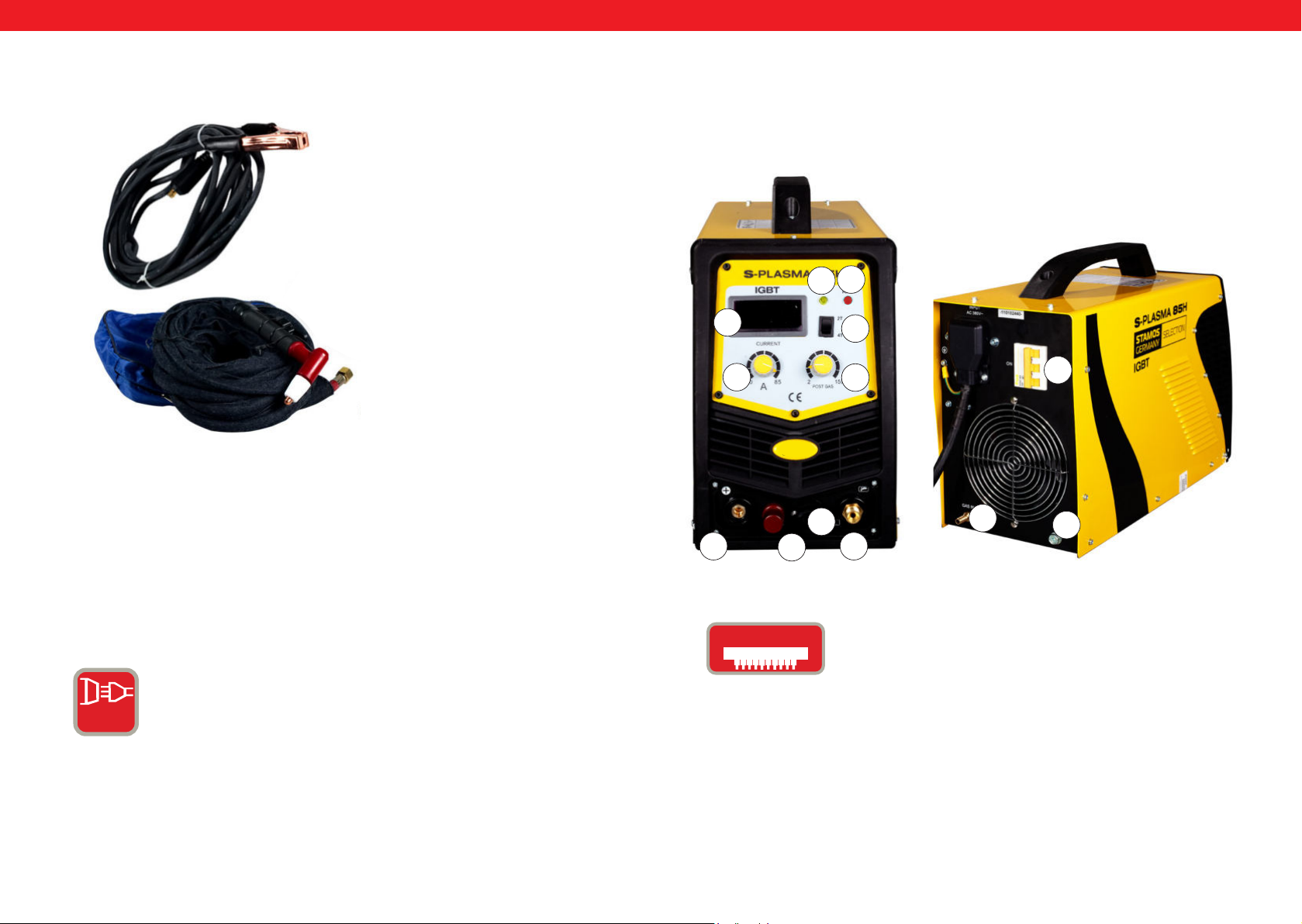
Accessoires pour découpeur plasma
1
1. Câble de masse
2. Torche plasma
2
S-PLASMA 85H | S-PLASMA 85CNC
FACE AVANT FACE ARRIÈRE
19
2
4
1
12
11
0
20
5
20. Pour le modèle S-PLASMA 85CNC
RACCORDEMENT SECTEUR POUR S-PLASMA 85H / S-PLASMA
85CNC
COURANT DE HAUTE INTENSITÉ = cet appareil fonctionne
avec des prises triphasées (400V +/- 10%)
6
IGbT
3 PH
34 35
Rev. 04.04.2022 Rev. 04.04.2022
7
Le transistor bipolaire à grille isolée (de l‘anglais Insulated
Gate Bipolar Transistor - IGBT) est un dispositif semiconducteur qui est de plus en plus utilisé de plus en plus
dans l‘électronique de puissance, car il combine les avantages
du transistor bipolaire (par exemple: grande simplicité de
commande, haute tension de blocage, robustesse des postes
à souder) et les avantages du transistor à effet de champ
(pilotage presque sans puissance). Ce qui est avantageux, c‘est
aussi la robustesse certaine face aux courts circuits, car l‘IGbT
limite la charge de courant. Les IGbT sont une évolution de la
technologie MOSFET
8
9
Page 19
FR
PODŁĄCZENIE CNC
Aby podłączyć przecinarkę do maszyny CNC należy podłączyć dwa piny we
wtyczce: pin 3 oraz pin 4. CNC będzie działać w przypadku gdy maszyna CNC
będzie włączona, w przeciwnym przypadku będzie działało tylko cięcie ręczne.
Pin 1 oraz 2 są podłączone fabrycznie i jest to podłączenie tylko i wyłącznie do
cięcia ręcznego:
FR
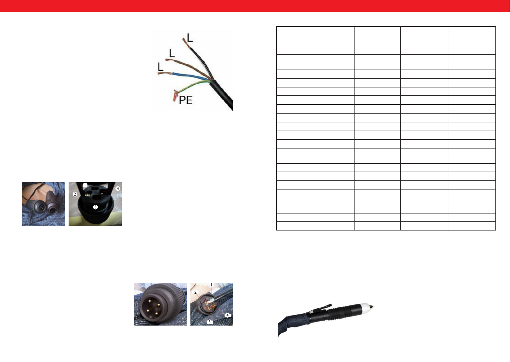
Raccordement S-Plasma 85H + 125H / 85CNC + 125CNC
Plan de raccordement au secteur
Le l jaune-vert est destiné à la prise du conducteur de protection (PE). Les trois phases
(noir, marron et bleu) peuvent être connectées
au choix à L1, L2 et L3. Les travaux sur le système électrique doivent uniquement être effec-
tués par un électricien qualié.
ATTENTION!!!
Seul un électricien qualié peut connecter un poste à souder avec raccordement
haute tension!
BRANCHEMENT DU MOCN 125CNC
Pour raccorder le découpeur plasma à la machine MOCN (Machine-outil à commande numérique), branchez les deux prises dans le connecteur.
Prise 4: Pôle positif
Prise 2: Pôle négatif
Détails techniques
S-Plasma 55H S-Plasma 85H
et
S-Plasma
85CNC*
Tension d‘entrée 230V
1-phasé
Fréquence 50/60 Hz 50 Hz 50 Hz
Intensité d‘entrée 16A 19 A 20 A
Tension en circuit ouvert 230 V 280 V 300 V
Classe de protection du capot IP20S IP20S IP21S
Classe d‘isolation F F F
Protection anti-surcharge oui oui oui
Refroidissement Ventilateur Ventilateur Ventilateur
Électrovanne oui oui oui
Facteur de marche à A.max 60% 60% 60%
A pour un facteur de marche de
100%
Courant de découpage 10-55 A 20-85 A 10-125 A
Amorçage Contakt Non-Contakt Non-Contakt
Profondeur de découpe 17 mm 27 mm 34 mm
Largeur de découpe 1 mm 1,2 mm 1,4 mm
Raccordement compresseur 4,5 bar,30-100 1/
Poids net 9.4 kg 19,5 kg 30 kg
Dimensions LxlxH (mm) 530/380/380 660/370/450 740/380/530
42,6 65,8 96,8
min.
400V
triphasé
5,5 bar,
175 l/min.
S-Plasma 125H
et
S-Plasma
85CNC*
400V
triphasé
7 bar
250 l/min
BRANCHEMENT DU MOCN 85CNC
Pour raccorder le découpeur plasma à la machine MOCN (Machine-outil à commande numérique), branchez les deux prises dans le connecteur: Broche 3 et 4. La
fonction MOCN fonctionne uniquement si la machine MOCN est en état de marche.
*Attention: les modèles S-Plasma 85CNC et S-Plasma 125CNC comportent un raccord CNC supplémentaire. Cependant, ces 2 modèles de découpeuse plasma sont
déjà équipés d’un chalumeau.
Cependant, il est possible d‘effectuer une découpe manuelle si la machine MOCN
n’est pas allumée.
Broche 3: Pôle positif
Broche 4: Pôle négatif
36 37
Rev. 04.04.2022 Rev. 04.04.2022
Page 20
FR
Installation
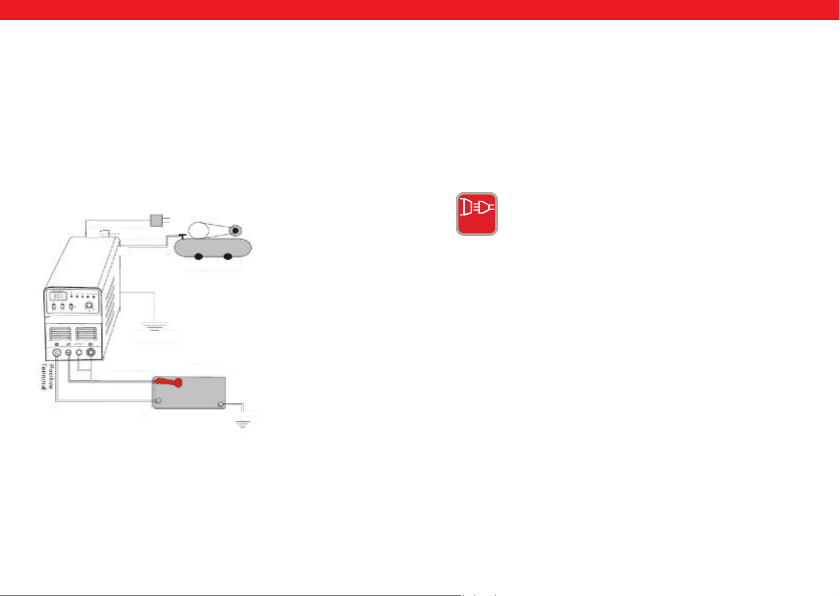
1. Chaque découpeur plasma est équipé d‘un câble électricité et doit être connecté à une alimentation en courant conforme à la tension d‘entrée de l‘appareil.
2. Le cordon d‘alimentation doit être bien branché pour éviter l‘oxydation. Si
possible, vérier la tension du courant avec un instrument de mesure.
Raccordement des connecteurs (Schéma de l‘installation)
FR
Utilisation
Actionnez l‘interrupteur sur le panneau arrière, la lumière de contrôle s‘allume et la
valeur du courant actuel est indiquée.
Ajustez conformément la pression du gaz et ouvrez la valve de compression.
Appuyez sur le bouton de contrôle de la torche plasma, le ventilateur s‘allume
et vous pouvez entendre et voir l‘arc électrique.
Réglez le courant de découpage selon l‘épaisseur de vos pièces à découper. Approchez la buse de cuivre de la torche de découpage vers la pièce d‘ouvrage (à peu près
2mm de la pièce de travail avec l‘arc), appuyez sur le bouton de la torche jusqu‘à ce
que l‘arc apparaisse puis levez la buse de découpage à 1mm de la pièce d‘ouvrage et
commencez à découper.
OUT
S-Plasma 125H
Torche de découpe
Câble de masse
Réglage de la
pression d‘air
IN
Tuyau d‘air
400V
Luftkompressor
Mise à la terre du châssis
Pièce d‘ouvrage
Mise à la terre
3 PH
COURANT DE HAUTE INTENSITÉ = cet
appareil fonctionne avec des prises triphasées (400V +/- 10%)
38 39
Rev. 04.04.2022 Rev. 04.04.2022
Page 21
FR
FR
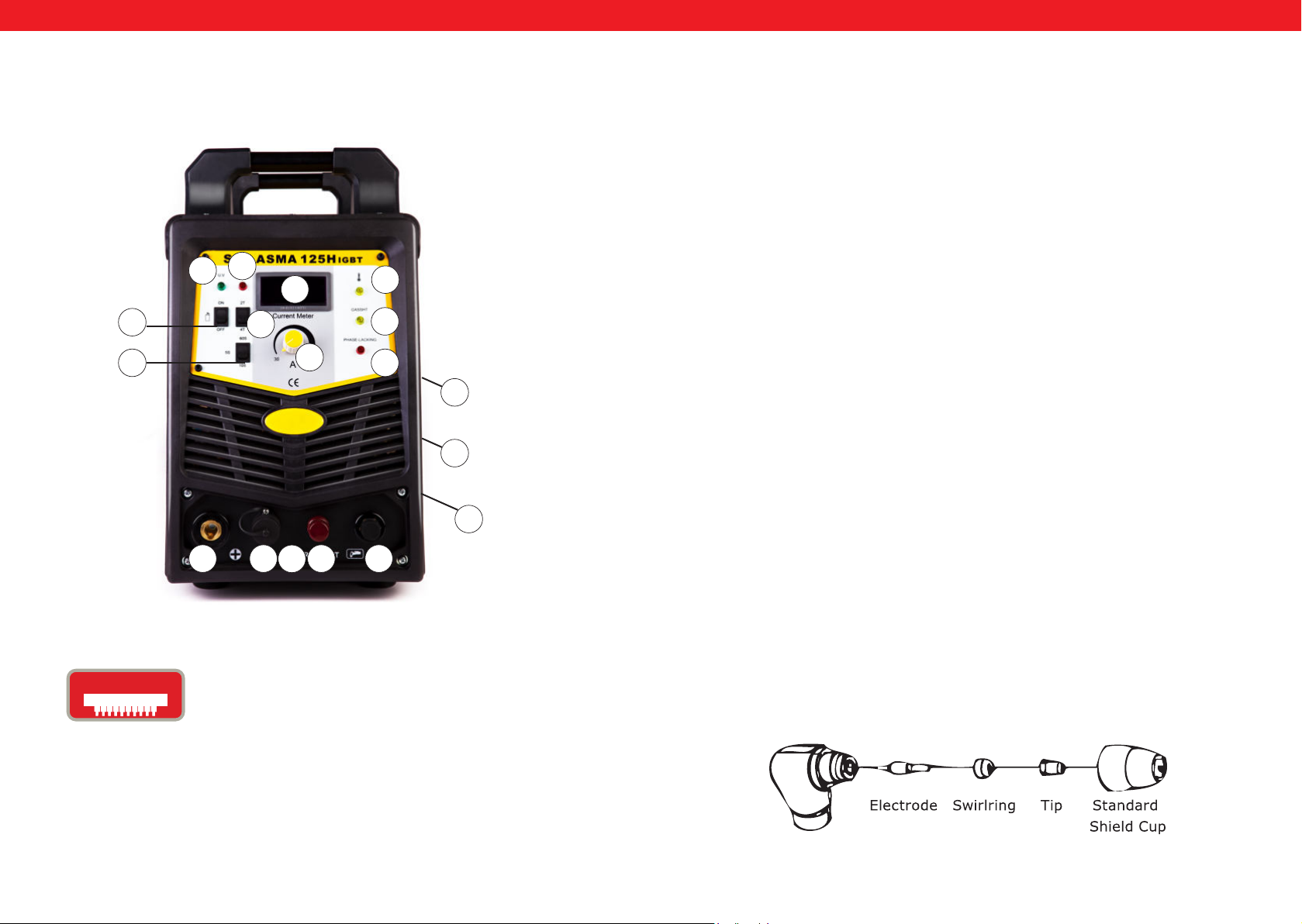
S-PLASMA 125H | S-PLASMA 125CNC
17
16
4
15
14
7
13
1
10 6 5
20
2
18
19
MISE EN FONCTIONNEMENT
A. Déballage
Déballez chaque pièce de la boîte et assurez-vous que vous avez bien toutes
les pièces présentes sur la liste d‘emballage.
B. Espace de travail
Assurez-vous que votre aire de travail soit bien ventilée. L‘appareil est refroidi grâce à
un ventilateur axial apportant un ux d‘air sur l‘électronique à travers le panneau de
contrôle.
Indication! Le revêtement doit être installé de manière à s‘assurer que les trous
d‘aération se trouvent vers l‘avant de l‘appareil. Laissez environ 15cm sur le devant et
les côtés an de permettre le nettoyage. Si la machine est utilisée sans le refroidissement approprié, la durée du facteur de marche en sera grandement réduite.
C. Branchement des câbles
Chaque appareil est équipé d‘un cordon d‘alimentation permettant l‘apport en cou-
0
9
8
rant et tension. Si l‘appareil est connecté à une alimentation fournissant une tension
plus élevée que celle appropriée ou si une mauvaise phase est réglée, cela peut conduire à de sérieux dommages sur l‘appareil. Cela n‘est pas couvert par la garantie sur
l‘équipement et l‘utilisateur sera tenu responsable de telles situations.
D. Raccordement de la torche
Connectez la torche à l‘appareil en branchant le tube à air xé au bout de la torche
au raccordement pour la torche se trouvant à l‘avant de l‘appareil. Assurez-vous que
le branchement est sécurisé en le serrant légèrement avec une clé. Faites cependant
attention à ne pas trop serrer.
SCHEMA TORCHE
20. Pour le modèle S-PLASMA125CNC
IGbT
40 41
Le transistor bipolaire à grille isolée (de l‘anglais Insulated
Gate Bipolar Transistor - IGBT) est un dispositif semiconducteur qui est de plus en plus utilisé de plus en plus
dans l‘électronique de puissance, car il combine les avantages
du transistor bipolaire (par exemple: grande simplicité de
commande, haute tension de blocage, robustesse des postes
à souder) et les avantages du transistor à effet de champ
(pilotage presque sans puissance). Ce qui est avantageux, c‘est
aussi la robustesse certaine face aux courts circuits, car l‘IGbT
limite la charge de courant. Les IGbT sont une évolution de la
technologie MOSFET.
Rev. 04.04.2022 Rev. 04.04.2022
Page 22

FR FR
A. Assemblage de la torche
Inclinez la torche avec son capuchon de protection vers le haut et dévissez la buse
protectrice du pistolet. (Le capuchon de protection maintient la tuyère, le diffuseur
en céramique et l‘électrode). Enlevez la buse protectrice, le diffuseur en céramique et
l‘électrode. Assemblez à nouveau l‘électrode, le diffuseur en céramique et la pointe.
Remplacez les parties usées si nécessaire. Mettez le capuchon de protection sur la tête
du pistolet et vissez-le jusqu‘à ce qu‘il soit bien serré. Si vous rencontrez une quel-
conque résistance durant ce processus, vériez le letage et l‘ordre d‘assemblage des
différentes parties avant de commencer à travailler.
Indication
Dans le cas de pistolets n‘ayant pas d‘électrode réglable, il est nécessaire de serrer
l‘électrode en utilisant des pinces an de s‘assurer que la connexion électrique se fasse
correctement.
UTILISATION
A. Mise en marche
Enclenchez l‘interrupteur sur la position « ON ». Positionnez-vous de manière à pouvoir lire la pression de l‘air sans problème. Appuyez sur l‘interrupteur de la torche (de
l‘air sortira alors du pistolet), réglez la pression de l‘air sur env. 6-7 (bar) et appuyez sur
l‘interrupteur à nouveau.
Remarque
La plage de pression communément acceptée est de 5-8 bars. Vous pouvez tester quelle
pression est la plus appropriée à votre travail, mais il ne faut pas oublier que les consommables s‘endommagent lorsque la pression est trop faible. Assurez-vous de mettre
la pince de masse sur la pièce d‘ouvrage. Connectez la pince avec la partie principale de
la pièce et non à la partie qui est à enlever.
2. Entretien hebdomadaire
Vériez que le ux d‘air fonctionne normalement. Aspirez toute saleté ou poussière de
la machine dans sa totalité sans oublier le ltre à air.
3. Découpe à distance
Dans certains cas, il est plus adapté de procéder à la découpe avec le diffuseur éloigné
d‘environ 1,5-3 mm de la pièce d‘ouvrage. Cela permet de réduire la quantité de matériel projeté dans le diffuseur et de rendre la pénétration d‘une large coupe dans le ma-
tériel plus efcace. La découpe à distance est à utiliser pour la découpe de pénétration
et le rainurage. Elle peut aussi être utilisée lors de la découpe de tôle an de réduire
les projections qui pourraient endommager la buse externe.
4. Perforer
Pour perforer, placez la pointe à environ 3,2 mm au-dessus de la pièce d‘ouvrage.
Inclinez légèrement la torche an de repousser les projections de votre direction.
Actionnez l‘arc principal et abaissez la pointe de la torche jusqu‘à ce que l‘arc principal
se créé et que les étincelles se forment. Commencez par tester la perforation sur un
objet non réutilisable. Lorsque cela fonctionne sans problème, vous pouvez perforer
sur la ligne de coupe préétablie.
ENTRETIEN
Examinez la torche, faites attention aux dommages d‘usure, aux ssures et aux câbles
dénudés. Remplacez ou réparez la torche avant d‘utiliser l‘appareil. Une buse de torche trop abimée provoque une diminution de la vitesse, une chute de tension et une
découpe inégale. On reconnait une buse de torche usée lorsque son ouverture est
allongée ou trop grosse. L‘extérieur de l‘électrode ne peut pas faire moins de 3,2mm.
Remplacez-la lorsque celle-ci est usée. Si la buse ne se visse pas facilement, examinez
le letage.
B. Découpe
1. Découpe en contact continue (drag cutting)
Tenir le diffuseur du pistolet au-dessus de la pièce d‘ouvrage, appuyer sur l‘interrupteur
de la torche et avancer le diffuseur jusqu‘à ce que qu‘il soit en contact avec la pièce et
que l‘arc de découpe soit établi. Vous pouvez ensuite bouger la torche dans la direction
désirée tout en maintenant le diffuseur légèrement incliné et en contact avec la pièce.
Cette méthode de travail est appelée découpe en contact continu (drag cutting). Les
Attention: Assurez-vous toujours que l‘alimentation est coupée lors
du changement de la buse et de l‘électrode.
Contrôle
1. Le châssis doit toujours être relié à la terre en sécurité.
2. Examinez si tous les raccordements sont reliés correctement.
3. Vériez si le cordon d‘alimentation est alimenté avec une tension correcte.
4. Veillez que les câbles et les tuyaux ne soient pas endommagés ou usés.
mouvements trop rapides sont à éviter. Si des étincelles sont projetées de la pièce
d‘ouvrage vers le haut, c‘est signe que vous devez ralentir vos mouvements. Votre vitesse est bonne lorsque les étincelles sont projetées ensemble sous la pièce d‘ouvrage.
Assurez-vous que le matériel est bien coupé avant d‘aller plus loin dans la découpe.
Régulez la vitesse si nécessaire.
42 43
Rev. 04.04.2022 Rev. 04.04.2022
Page 23

INSTRUKCJA
PL
Niniejsza instrukcja obsługi zawiera opisy, instrukcje obsługi i zasadnicze procedury
konserwacyjne dotyczące przecinarki plazmowej S-Plasma 85H/125H rmy Stamos
Germany. Należy w sposób wyczerpujący zapoznać się z niniejszą instrukcją obsługi.
Całkowite zrozumienie właściwości i możliwości zastosowania urządzenia zapewnia
prawidłowe jego zastosowanie.
OSTRZEŻENIE
• Należy chronić siebie i inne osoby przed okaleczeniami. Należy uważnie przeczytać
i postępować zgodnie z opisanymi środkami ostrożności.
• Tylko wykwalikowane osoby mogą zajmować się naprawami, eksploatacją,
konserwacją oraz inspekcjami urządzenia.
• W przypadku stosowania urządzenia nie wolno dopuszczać do miejsca eksploatacji
osób trzecich, w szczególności dzieci.
CIĘCIE może powodować pożar lub eksplozję.
S-PLASMA 55H | S-PLASMA 85H
S-PLASMA 125H | S-PLASMA 85CNC
S-PLASMA 125CNC
Gorący metal i iskry są rozprzestrzenianie przez łuk plazmy. Przemieszczające się
iskry lub gorące odłamki metalu, jak również rozgrzany element obrabiany i wyposażenie urządzenia mogą powodować powstanie pożaru lub poparzenia. Należy sprawdzić otoczenie robocze i upewnić się przed zastosowaniem urządzenia, że można
w nim je eksploatować.
• Należy usunąć wszystkie elementy palne w promieniu 10,7 m od urządzenia spa-
walniczego.
• Jeśli nie jest to możliwe, znajdujące się w otoczeniu przedmioty należy odpowied-
nio przykryć.
• Nie należy ciąć w miejscu, w którym przemieszczające się iskry mogłyby trać na
palny materiał.
• Należy chronić siebie i inne osoby przed rozprzestrzeniającymi się iskrami oraz
gorącym metalem.
• Należy być zawsze uważnym, ponieważ iskry i gorące materiały mogą przedosta-
wać się podczas cięcia z łatwością przez małe szczeliny i otwory.
• Należy zawsze sprawdzać, czy nie powstaje ogień. W pobliżu konieczne jest przy-
gotowanie gaśnicy.
• Należy mieć świadomość, że cięcie w obrębie stropu, podłoża lub na ograniczonym
obszarze może powodować powstawanie ognia po przeciwległej, niewidocznej
stronie obrabianego materiału.
expondo.de
44 45
Rev. 04.04.2022 Rev. 04.04.2022
Page 24

PL
PL
Nie należy ciąć zamkniętych pojemników takich jak np. zbiorniki lub
naczynia
Należy podłączyć kabel roboczy z gniazdkiem znajdującym się w pobliżu miejsca roboczego, tak aby uniknąć układania kabla zasilającego w całym pomieszczeniu, co powodowałoby, że mógłby się znaleźć na nieznanym podłożu powodując porażenie elektryczne,
powstawanie iskier lub wybuch pożaru.
• Nie należy używać przecinarki plazmowej do rozmrażania zamarzniętych rur.
• Nie należy ciąć pojemników, które mogą zawierać materiały palne. Muszą wcześniej
zostać opróżnione i dokładnie oczyszczone.
• Nie należy ciąć w atmosferze zawierającej wybuchowe cząsteczki pyłu lub oparów.
• Nie należy ciąć cylindrów, przewodów lub zbiorników pod ciśnieniem.
• Nie należy ciąć pojemników, w których przechowywane były substancje palne.
• Należy nosić odzież ochronną pozbawioną oleju np. skórzane rękawice, grube ko-
szule, spodnie bez nabijanych elementów, wysokie buty oraz nakrycie głowy.
• Nie należy umiejscawiać miejsca pracy na lub nad palnymi powierzchniami.
• Należy usunąć wszystkie elementy palne np. zapalniczki butanowe lub zapałki zanim
rozpoczęta zostanie procedura cięcia.
• Należy postępować zgodnie z warunkami przewidzianymi do przeprowadzenia
prac a w pobliżu miejsca roboczego przechowywać gaśnicę. W przypadku kontaktu
z elektrycznie naładowanymi częściami może dojść do poważnego porażenia lub poważnych oparzeń. Końcówka i obwód roboczy są naładowane elektrycznie w chwili
gdy uruchomione zostanie zasilanie. Obwód wejściowy prądu i wewnętrzny obwód
zasilania maszyny są także pod napięciem po włączeniu zasilania.
Cięcie łukiem plazmowym wymaga wysokiej wartości napięcia w Voltach do zajarzenia
łuku oraz jego utrzymania podobnie jak w przypadku spawania (200 do 400 V DC),
ale urządzenie dysponuje uchwytem wyposażonym w blokadę bezpieczeństwa, która
automatycznie wyłącza urządzenie jeśli doszło do odpadnięcia osłony ochronnej lub
końcówka elektrody dotknęła obszaru dyszy. Niewłaściwa instalacja lub uziemienie wyposażenia urządzenia stanowią duże zagrożenie.
PORAŻENIE ELEKTRYCZNE JEST NIEBEZPIECZNE DLA ŻYCIA.
• Nie należy nigdy dotykać naładowanych części elektrycznych.
• Należy nosić suche, pozbawione dziur, izolowane rękawice i odzież ochronną.
• Należy odizolować się od przedmiotu i podłoża stosując suche maty izolacyjne lub
plandeki osłonowe, które muszą być dostatecznie duże, aby uniknąć wszelkiego kontaktu ciała z podłożem i obiektem roboczym.
• Nie należy dotykać żadnych elementów uchwytu plazmowego, jeśli pozostają
one w kontakcie z przedmiotem roboczym lub z podłożem.
• Należy wyłączyć zasilanie, zanim zostaną sprawdzone, wyczyszczone lub wymienione części uchwytu plazmowego.
• Należy wyłączyć zasilanie w przypadku instalacji urządzenia lub odizolować się od-
powiednio od przedmiotu i / lub podłoża poprzez stosowanie suchych mat izola-
cyjnych.
• Należy sprawdzić i upewnić się, że drut uziemiający kabla zasilającego jest prawidło-
wo połączony ze stykiem uziemienia lub wtyk kabla jest połączony z prawidłowo
uziemionym wyjściem gniazda.
• Należy zawsze dokonać werykacji przyłącza uziemienia.
• Zanim przygotowane zostanie połączenie na wejściu, należy przygotować odpo-
wiedni przewód uziemiający.
• Należy regularnie sprawdzać kabel zasilania pod kątem uszkodzeń i niezaizolowanych części. W przypadku stwierdzonych szkód należy niezwłocznie wymieniać kable, ponieważ ¬niezaizolowane kable mogą prowadzić do zgonu.
• Należy wyłączyć urządzenie, jeśli nie jest używane.
• Kabel należy poddać inspekcji i wymianie, jeśli doszło do nadmiernego obciążenia
przewodu lub jest uszkodzony.
• Nie należy owijać kabla urządzenia dookoła własnego ciała.
• Należy dokonać uziemienia obrabianego elementu z wykorzystaniem dobrego elek-
trycznego podłoża uziemiającego.
• Należy stosować tylko wyposażenie w dobrym stanie.
• Uszkodzone komponenty urządzenia należy naprawiać lub niezwłocznie wymieniać.
• Należy nosić pas bezpieczeństwa w przypadku prac na wysokościach.
• Wszystkie elementy i osłony przechowywać w jednym miejscu.
• Nie należy przebywać w pobliżu końcówki uchwytu plazmowego oraz łuku po uru-
chomieniu elementu wyzwalającego.
• Należy zamocować kabel roboczy używając metalicznego styku przy przedmiocie
obrabianym (nie może być to element, który mógłby odpaść) lub też umieścić stół
roboczy tak blisko urządzenia tnącego, na ile jest to konieczne z punktu widzenia
obróbki.
• Należy odizolować zacisk
Po odłączeniu kabla zasilającego urządzenie może być jeszcze pod
ZNACZĄCYM NAPIĘCIEM STAŁYM
Należy wyłączyć urządzenie, odłączyć przewód zasilania, sprawdzić napięcie w obrębie
kondensatora wejściowego i upewnić się, że napięcie jest bliskie zeru w chwili kontaktu z urządzeniem. Należy sprawdzić kondensatory pod kątem informacji zawartych
w rozdziale konserwacja i instrukcja obsługi zanim użytkownik dotknie dowolnej części
urządzenia.
PORAŻENIE ELEKTRYCZNE MOŻE PROWADZIĆ DO ŚMIERCI
W obrębie prostownika pewne komponenty, które nie są bezpieczne z punktu widzenia
eksploatacji, mogą eksplodować gdy uruchomione zostanie ich zasilanie. Należy zawsze
chronić twarz oraz nosić koszulę z długimi rękawami w przypadku obsługi prostownika.
46 47
Rev. 04.04.2022 Rev. 04.04.2022
Page 25

PL
PL
EKSPLODUJĄCE CZĘSCI mogą prowadzić do okaleczeń.
Iskry oraz części metalowe odpryskują od powierzchni spawania.
LATAJĄCE ISKRY mogą powodować okaleczenia.
• Należy nosić odpowiednią ochronę twarzy lub okulary bezpieczeństwa z boczną
osłoną.
• Należy nosić odpowiednie środki ochrony ciała aby chronić skórę.
• Należy nosić odporne na działanie ognia zatyczki do uszu oraz inne środki ochrony
słuchu aby zapobiec przedostawaniu się iskier do uszu.
• Łuk podczas cięcia powoduje powstawanie promieni widocznych i niewidocznych
(ultraolet i podczerwień), które mogą powodować oparzenia oczu i skóry.
PROMIEŃ ŁUKU może powodować poparzenia oczu i skóry.
• Należy nosić ochronę twarzy (kask lub osłonę) w odpowiednim kolorze, stanowiącą
ltr chroniący twarz i oczy podczas cięcia.
• Standardy bezpieczeństwa przewidują kolor nr 9 (nr 8 jako minimum) dla wszystkich wartości natężenia mniejszych niż 300 A. Zabarwienia o niższej ltracji mogą
być wykorzystywane, jeśli łuk przenika całkowicie przez przedmiot roboczy.
• Należy nosić okulary bezpieczeństwa z osłoną boczną pod kaskiem lub osłoną.
• Należy używać osłon ochronnych lub elementów odgradzających aby chronić inne
osoby przed oślepiającym światłem lub iskrami; należy ostrzec inne osoby, aby nie
patrzyły w stronę łuku światła.
• Należy nosić odzież ochronną, która została wyprodukowana z odpornego na działanie ognia, trwałego materiału (skóra, bawełna lub wełna) oraz odpowiednie obuwie
robocze.
liwiają wyprowadzanie stałego przepływu gazu ochronnego. Ciśnienie tego przepływu
gazu umożliwia kontrolowanie promienia strumienia plazmy.
Wskazówka! Maszyna przewidziana jest do tylko do zastosowania sprężonego powie-
trza jako gazu.
Regulacja prądu
Automatyczna funkcja ograniczenia natężenia w obwodzie chroni przed przepięciami
zapewniając zachowanie wartości ujętej w technicznej karcie danych.
Ochrona termiczna
Obwód ochrony termicznej uruchamia się w przypadku gdy urządzenie przekracza
czas uruchomienia. To prowadzi do zatrzymania się maszyny.
Duty Cycle
Czas uruchomienia to wartość procentowa trwania eksploatacji (mierzona w minutach) w formie 10-minutowego okresu, podczas którego maszyna jest eksploatowana
w sposób nieprzerwany w typowych warunkach temperaturowych. Jeśli przekroczone
zostaną parametry okresu uruchomienia spowoduje to uruchomienie systemu chroniącego przed przegrzaniem, który wstrzyma pracę urządzenia aż do schłodzenia do
normalnej temperatury roboczej. Nieprzerwane przekraczanie parametrów przewidywanego czasu uruchomienia może prowadzić do nadmiernego uszkodzenia urządzenia.
PLAZMA
Ogólne informacje dotyczące plazmy. Przecinarka plazmowa działa poprzez zastosowanie gazu pod ciśnieniem np. powietrza. Na środku kanału znajduje się ujemnie naładowana elektroda, a dysza znajduje się dokładnie pod nią. Pierścień obrotowy powoduje,
że strumień plazmy obraca się z dopuszczalną prędkością. Jeśli ujemna elektroda zostanie zasilona energią a końcówka dyszy będzie miała kontakt z metalem, wskutek tego
połączenia dojdzie do powstania obwodu. Teraz między elektrodą i metalem generowana jest iskra zapłonowa.
Kiedy dopływający gaz przepływa przez rurę, iskra zapłonowa podgrzewa gaz aż do
osiągnięcia czwartego stanu. Ta reakcja powoduje, że dochodzi do przemieszczenie
kierowanej plazmy o temperaturze ok. 16.649° C lub wyższej z prędkością 6,096 m/
sek oraz redukcji metalu do oparów i stopionych pozostałości. Plazma sama w sobie
przewodzi prąd elektryczny. Obwód roboczy, który umożliwia powstanie łuku, istnieje
w czasie gdy do elektrody doprowadzane jest zasilanie a plazma pozostaje w kontakcie
z materiałem do obróbki. Dysza tnąca dysponuje drugą grupą kanałów. Te kanały umoż-
48 49
Rev. 04.04.2022 Rev. 04.04.2022
Page 26
PL
PL
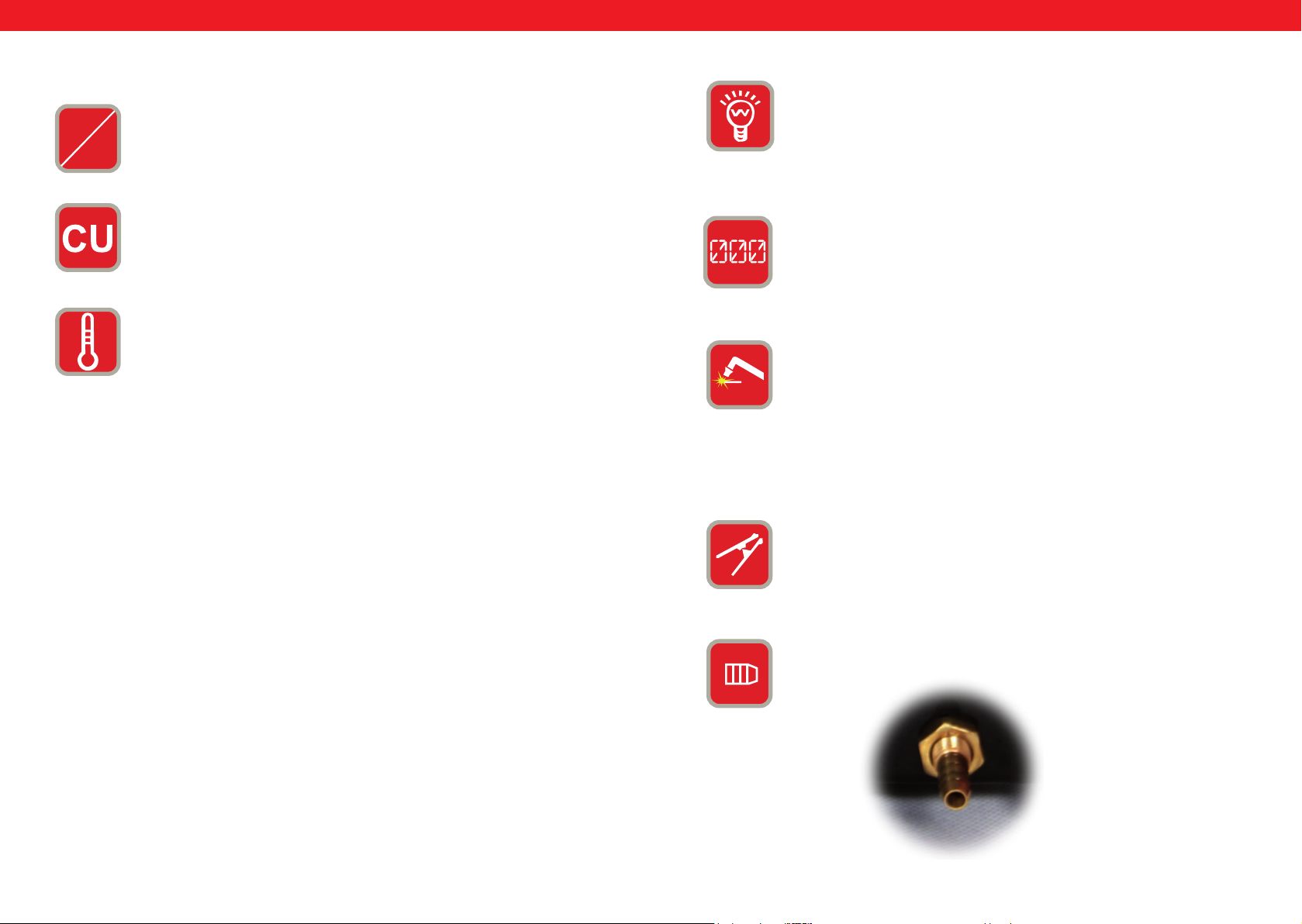
LEGENDA:
0.
On
Off
1.
2.
Włącznik/ wyłącznik
Regulator prądu
CURRENT = Możliwość regulacji prądu głównego
Przeciążenie / awaria = lampka zapala się w przypadku wystąpienia
dwóch
sytuacji:
a) jeżeli maszyna ma awarię i nie może być eksploatowana.
b) jeżeli spawarka przekroczyła standardowy czas przeciążenia,
przechodzi w tryb bezpieczeństwa a następnie wyłącza się. Oznacza
to, że urządzenie w ramach kontroli temperatury i przegrzania
przechodzi w tryb spoczynku. Podczas tego procesu zaświeca się
kontrolka ostrzegawcza na przednim panelu. W tej sytuacji nie trzeba
wyciągać wtyku zasilania z gniazdka. W celu schłodzenia urządzenia
wentylator może funkcjonować dalej. Jeżeli czerwona kontrolka nie
świeci się, to oznacza to, że urządzenie schłodziło się do temperatury
eksploatacji i może być ponownie użytkowane.
3.
4.
5.+6.
7.
WSKAŹNIK ZASILANIA = po włączeniu maszyny zapala się ta
kontrolka.
Wyświetlacz LED = wyświetlą bieżącą wartość natężenia prądu.
Przyłącze uchwytu (palnika) plazmowego:
Wysoka gęstość energetyczna łuku świetlnego plazmy umożliwia
osiągnięcie dużej prędkości cięcia przy jednoczesnym zapewnieniu
wysokiej jakości cięcia.
Nie jest wymagane stosowanie żadnego specjalnego, drogiego gazu;
stosowanie normalnego sprężonego powietrza oraz bezproblemowa
obsługa gwarantują wygodną eksploatację podczas obróbki zbiorników,
karoserii oraz stali w branży grzewczej, klimatyzacyjnej i wentylacyjnej
na obszarze instalacyjnym i sanitarnym.
Złącze przewodu masy
8.
GAS
GAZ/ podłączenie powietrza
AIR
50 51
Rev. 04.04.2022 Rev. 04.04.2022
Page 27
PL
PL
9.
10.
11.
12.
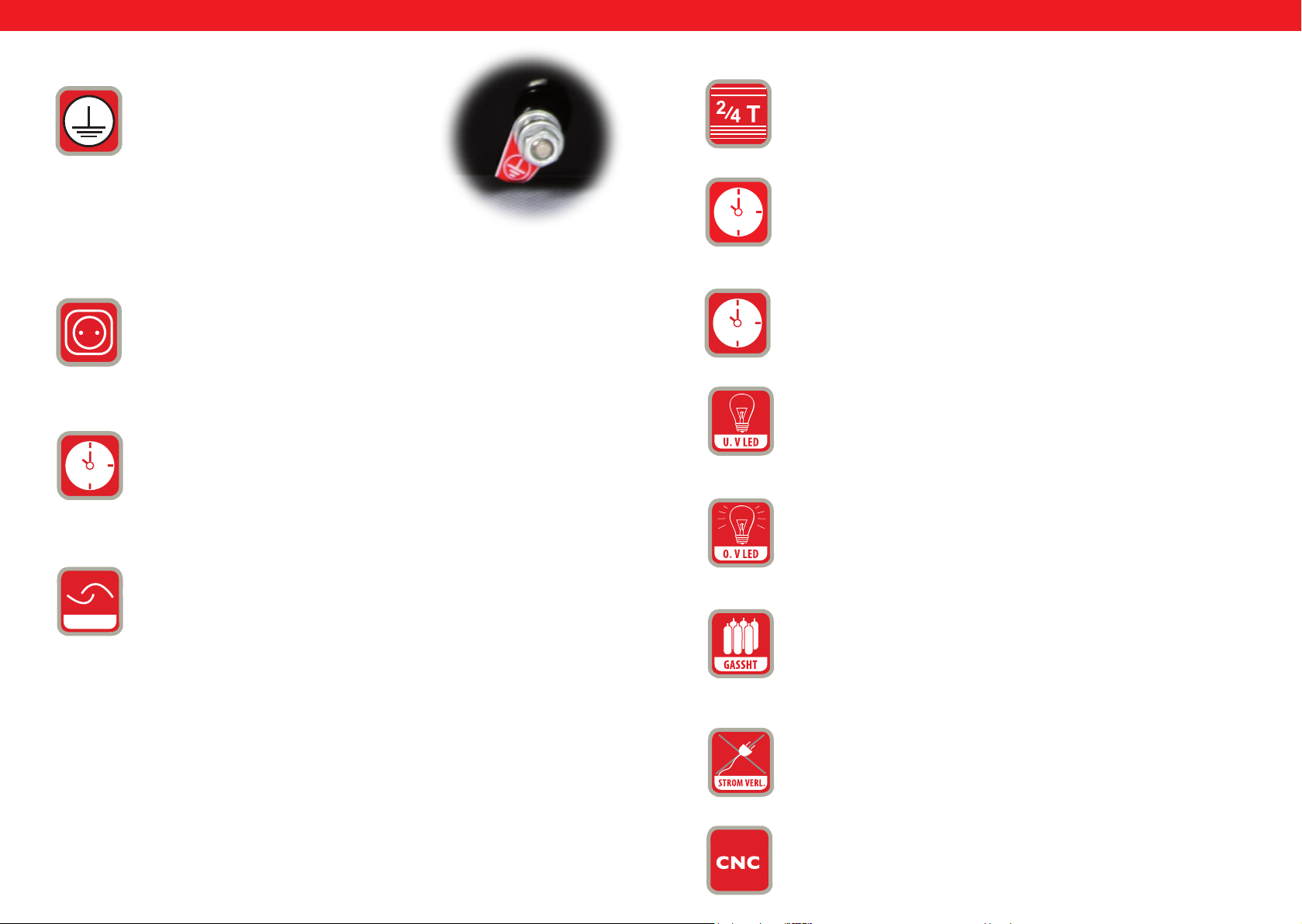
Uziemienie:
Z tyłu każdego urządzenia do spawania znajduje
się śruba oraz informacja o konieczności
zapewnienia odpowiedniego uziemienia. Przed
rozpoczęciem obsługi konieczne jest uziemienie
obudowy spawarki z użyciem kabla, którego
przekrój nie może być mniejszy niż 6 mm, aby
uniknąć potencjalnych problemów spowodowanych
wypływem ładunków elektrycznych.
Dodatkowe przyłącze zasilania do przewodu palnika plazmowego
POST TIME = Czas wypływu gazu po upływie ustawionego czasu
w interwałach sekundowych. Ta regulacja jest istotna aby schłodzić
stopione przecięte elementy po procedurze cięcia i zapewnić ochronę
przed utlenieniem.
13.
2T/4T przełącznik wyboru
14.
POST FLOW = Za pomocą tego przycisku można regulować czas
doprowadzania gazu po zakończeniu procedury.
15.
TEST GAS = ochrona
16.
U.V LED = Under Voltage LED. Jeśli napięcie spadnie poniżej 330
V podświetla się ta dioda LED
17.
O.V LED = Over Voltage LED. Jeśli napięcie wzrośnie powyżej 420V
podświetla się ta dioda LED
SWITCH
ROCKER SWITCH = Jeśli przecinarka (element tnący) nie jest ustawiona w określonej, automatycznie ustalonej pozycji, należy nacisnąć
przycisk startowy palnika tnącego aby rozpocząć procedurę cięcia.
Aby zakończyć cięcie należy zwolnić przycisk, ten typ cięcia plazmowego jest przydatny do cięcia krótkiej spoiny.
18.
GASSHT = Dioda ta podświetla się kiedy strumień gazu nie jest
dostępny lub jest niewystarczający.
Jeśli element tnący jest ustawiony w pozycji automatycznie ustalonej,
należy nacisnąć jeden raz przycisk palnika tnącego aby uruchomić łuk
plazmowy. W ten sposób możliwe jest cięcie w sposób nieprzerwany.
19.
Należy nacisnąć przycisk ponownie aby zakończyć cięcie. Ten typ cięcia plazmowego jest przydatny do cięcia dłuższych spoin
PHASEN STROMVERLUST = Jeśli do urządzenia nie są podłączone
3 fazy prądu a zatem podłączono tylko dwie lub jedną fazę, ta dioda
LED podświetla się a maszyna ¬wstrzymuje pracę
20
Gniazdo podłączenia CNC
52 53
Rev. 04.04.2022 Rev. 04.04.2022
Page 28
PL
PL
SCHEMAT PODŁĄCZENIA S-Plasma 55H
Przewód zasilający
Reduktor ciśnienia
sprężarki
Uziemienie obudowy
Sprężarka
powietrza
S-PLASMA 55 H
WIDOK Z PRZODU
32
0
11
4
1
567
WIDOK Z TYŁU
9 8
IGbT
Przewód masowy
Element obrabiany
Palnik tnący
Tranzystor bipolarny z izolowaną bramką elektrody
(z ang. Insulated Gate Bipolar Transistor, w skrócie IGBT)
jest elementem półprzewodnikowym, który stosuje się
w elektronicznych układach dużej mocy, ponieważ posiada
zalety tranzystora bipolarnego (np.: wysoka przewodność,
wysokie napięcie zaporowe, trwałość wykonania
w spawarkach) oraz zalety tranzystora polowego z izolowaną
bramką (zasterowanie prawie bez straty mocy). Do zalet
należy również odporność na zwarcia, ponieważ IGBT
ogranicza prąd obciążenia. Układy IGBT stanowią dalszy krok
rozwoju pionowych układów mocy MOSFET.
PRĄD NORMALNY: spawarka zasilana jest z jednej fazy (230V
+/- 10%)
1 PH
54 55
Rev. 04.04.2022 Rev. 04.04.2022
Page 29
PL
PL
Akcesoria przecinarek plazmowych
1
1. Zacisk masy
2. Palnik plazmy
2
S-PLASMA 85H | S-PLASMA 85CNC
WIDOK Z PRZODU
19
2
4
1
12
11
WIDOK Z TYŁU
0
20
7
Tranzystor bipolarny z izolowaną bramką elektrody
(z ang. Insulated Gate Bipolar Transistor, w skrócie IGBT)
jest elementem półprzewodnikowym, który stosuje się
w elektronicznych układach dużej mocy, ponieważ posiada
zalety tranzystora bipolarnego (np.: wysoka przewodność,
wysokie napięcie zaporowe, trwałość wykonania
w spawarkach) oraz zalety tranzystora polowego z izolowaną
bramką (zasterowanie prawie bez straty mocy). Do zalet
należy również odporność na zwarcia, ponieważ IGBT
ogranicza prąd obciążenia. Układy IGBT stanowią dalszy krok
rozwoju pionowych układów mocy MOSFET.
PRZYŁĄCZE SIECIOWE S-PLASMA 85H / S-PLASMA 85CNC
STARKSTROM
przyłącza trójfazowego (400V +/- 10%)
: = Te urządzenia pracują z zastosowaniem
5
20. Tylko dla modelu S-PLASMA 85CNC
6
IGbT
3 PH
56 57
Rev. 04.04.2022 Rev. 04.04.2022
8
9
Page 30
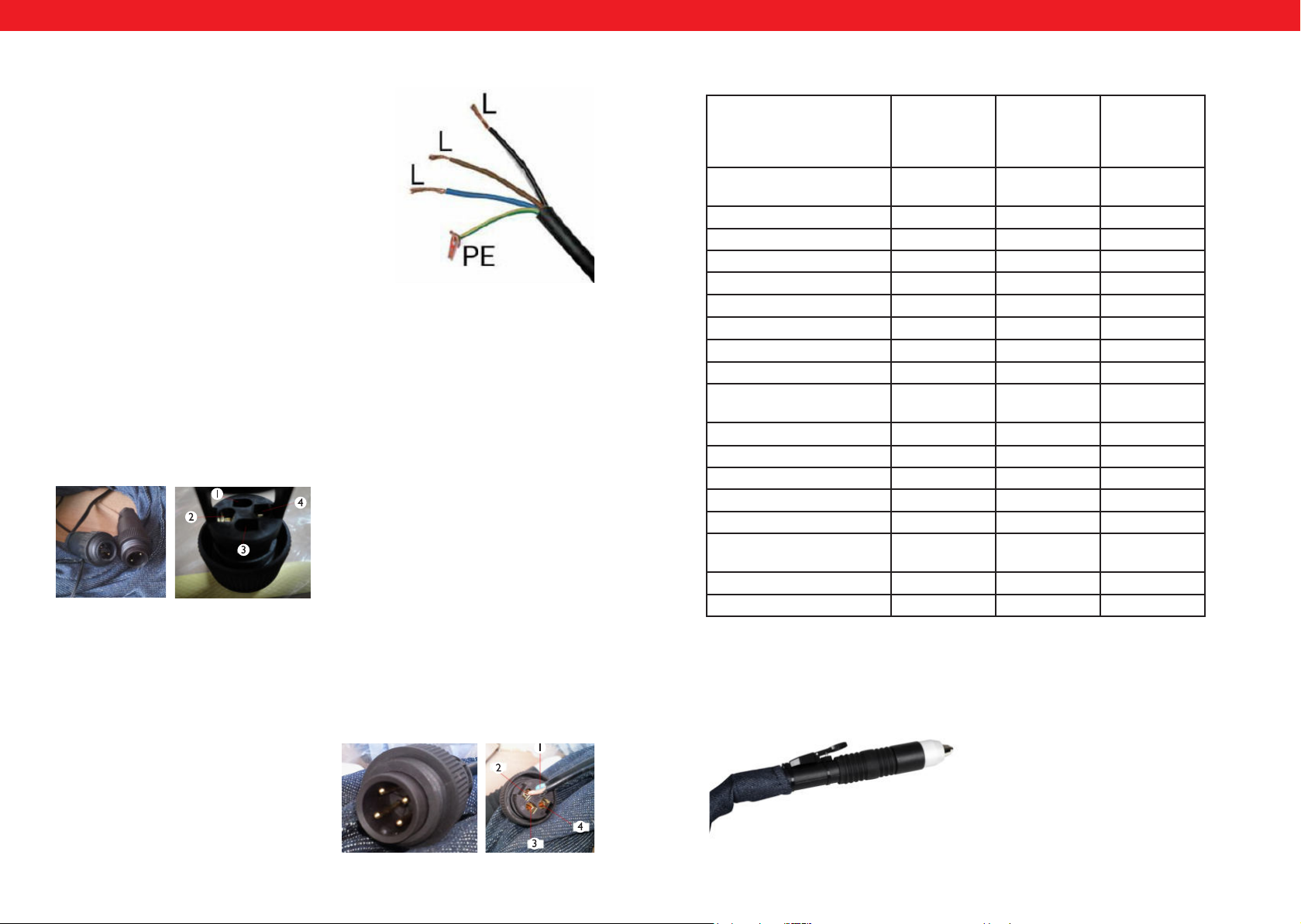
PL
PODŁĄCZENIE CNC
Aby podłączyć przecinarkę do maszyny CNC należy podłączyć dwa piny we
wtyczce: pin 3 oraz pin 4. CNC będzie działać w przypadku gdy maszyna CNC
będzie włączona, w przeciwnym przypadku będzie działało tylko cięcie ręczne.
Pin 1 oraz 2 są podłączone fabrycznie i jest to podłączenie tylko i wyłącznie do
cięcia ręcznego:
PL
Podłączenie S-Plasma 85H + 125H / 85CNC + 125CNC
Podłączenie do sieci
Żółto-zielona żyła jest przewidziana do
podłączenia przewodu ochronnego PE. Trzy
fazy (czarna, brązowa i niebieska) mogą być
w sposób dowolny podłączane do L1, L2 oraz
L3. Prace te może przeprowadzać tylko wykwalikowany elektryk.
Uwaga!!!
Urządzenia spawalnicze z przyłączem elektroenergetycznym mogą być podłączane
tylko przez wykwalikowanego elektryka!
PODŁĄCZENIE CNC S-PLASMA 125CNC
Aby podłączyć przecinarkę do maszyny CNC należy podłączyć dwa piny we wtyczce:
Pin 4: biegun dodatni
Pin 2: biegun ujemny
Szczegółowe dane techniczne
S-Plasma
55H
Zasilanie 230V
1 faza
Częstotliwość 50 Hz 50 Hz 50 Hz
Prąd wejściowy 16A 19 A 20 A
Napięcie biegu jałowego 230 V 280 V 300 V
Stopień ochrony obudowy IP20S IP20S IP21S
Klasa izolacji F F F
Ochrona przeciwprzepięciowa tak tak tak
Chłodzenie Wentylator Wentylator Wentylator
Zawór magnetyczny tak tak tak
Cykl pracy przy maksymalnym
prądzie A
Prąd A dla cyklu pracy 100%
Prąd cięcia 10-55 A 20-85 A 10-125 A
Zajarzenie łuku Kontakt Bezdotykowy Bezdotykowy
Grubość cięcia 17 mm 27 mm 34 mm
Szerokość cięcia 1 mm 1,2 mm 1,4 mm
Przyłącze kompresora 4,5 bar,30-100
Waga (netto) 9.4 kg 19,5 kg 30 kg
Wymiary dł./ sz./wys. (mm) 530/380/380 660/370/450 660/370/450
60% 60% 60%
42,6 65,8 96,8
1/min.
S-Plasma
85H oraz
S-Plasma
85CNC*
400V
3 fazy
5,5 bar,
175 l/min.
S-Plasma
125H oraz
S-Plasma
125CNC*
400V
3 fazy
7 bar
250 l/min
PODŁĄCZENIE CNC S-PLASMA 85CNC
Aby podłączyć przecinarkę do maszyny CNC należy podłączyć dwa piny we wtyczce: pin 3 oraz pin 4. CNC będzie działać w przypadku gdy maszyna CNC będzie
włączona, w przeciwnym przypadku będzie działało tylko cięcie ręczne. Pin 1 oraz 2 są
podłączone fabrycznie i jest to podłączenie tylko i wyłącznie do cięcia ręcznego:
Pin 3: biegun dodatni
Pin 4: biegun ujemny
58 59
Rev. 04.04.2022 Rev. 04.04.2022
* UWAGA! Modele S-Plasma 85CNC oraz S-Plasma 125CNC są wyposażone w dodatkowe gniazdo do podłączenia CNC. Ponadto te dwa modele przecinarek wyposażone są w prosty palnik:
Page 31
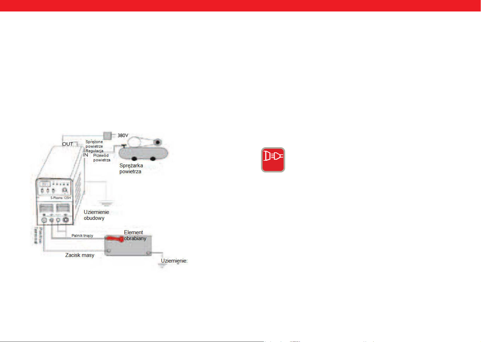
PL
PL
Instalacja
1. Każda przecinarka plazmowa jest wyposażona w kabel zasilania i musi zostać
podłączona z odpowiednim źródłem zasilania zgodnie z napięciem wejściowym
przecinarki plazmowej.
2. Kabel zasilania powinien zostać prawidłowo podłączony do wtyku lub włącz-
nika aby uniknąć oksydacji. Jeśli jest to możliwe należy sprawdzić przyrządem
pomiarowym czy napięcie mieści się w odpowiednim zakresie.
Podłączenie przewodów (szkic instalacyjny)
Obsługa
Należy włączyć włącznik na tylnym panelu, kontrolka się uruchamia i podawana
jest aktualna wartość prądu.
Należy ustawić ciśnienie gazu zgodnie z wymogami i otworzyć zawór kompresyj-
ny.
Należy nacisnąć przycisk sterowania na palniku tnącym, uruchamia się zawór,
widać i słychać łuk świetlny.
Należy ustawić strumień tnący stosownie do grubości obrabianego elementu.
Dyszę miedzianą palnika tnącego umieścić na obrabianym materiale (dyszę miedzianą w przypadku łuku świetlnego ustawiać ok. 2 mm od elementu obrabianego), nacisnąć przycisk na palniku aż zostanie uruchomiony łuk świetlny, unieść
nieco dyszę tnącą ok. 1 mm od elementu obrabianego i rozpocząć cięcie.
3 PH
STARKSTROM = Te urządzenia pracują z zastosowaniem
przyłącza trójfazowego (400V +/- 10%)
60 61
Rev. 04.04.2022 Rev. 04.04.2022
Page 32
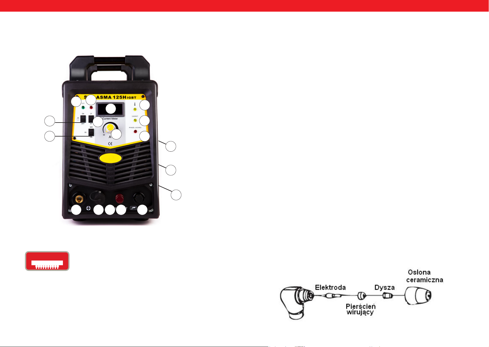
PL
PL
S-PLASMA 125H | S-PLASMA 125CNC
17
16
4
15
14
13
1
2
18
19
URUCHOMIENIE
A. Rozpakowanie
Należy wypakować wszystkie elementy z opakowania i upewnić się, że dostarczone
zostały wszystkie przedmioty ujęte w liście dostawy.
B. Otoczenie robocze
Upewnić się, że obszar roboczy jest dobrze wietrzony. Urządzenie jest chłodzone
z wykorzystaniem wentylatora osiowego, który dostarcza strumień powietrza poprzez
część tylną z wykorzystaniem układu elektronicznego.
(Wskazówka! Obudowa musi zostać zainstalowana w taki sposób, aby otwory odpowietrzające znajdowały się bliżej przedniej strony urządzenia). Należy pozostawić ok.
15 cm wolnej przestrzeni w części przedniej oraz 15 cm po obu stronach, aby umożliwić czyszczenie. Jeśli urządzenie jest obsługiwane bez zapewnienia wystarczającego
chłodzenia, znacznej redukcji ulega czas włączenia.
0
9
C. Połączenie wejściowe kabla
Każde urządzenie dysponuje głównym kablem zasilania, który zapewnia odpowiednie
natężenie prądu i napięcie dla urządzenia. Kiedy urządzenie podłączone jest do zasilania
przekraczającego niezbędne parametry lub też ustawiono nieprawidłową fazę, może to
prowadzić do poważnego uszkodzenia urządzenia. Nie jest to uwzględnione w ramach
warunków gwarancyjnych i będzie uznane jako wina użytkownika.
8
7
20. Tylko dla modelu S-PLASMA 125CNC
IGbT
62 63
Tranzystor bipolarny z izolowaną bramką elektrody
(z ang. Insulated Gate Bipolar Transistor, w skrócie IGBT)
jest elementem półprzewodnikowym, który stosuje się
w elektronicznych układach dużej mocy, ponieważ posiada
zalety tranzystora bipolarnego (np.: wysoka przewodność,
wysokie napięcie zaporowe, trwałość wykonania
w spawarkach) oraz zalety tranzystora polowego z izolowaną
bramką (zasterowanie prawie bez straty mocy). Do zalet
należy również odporność na zwarcia, ponieważ IGBT
ogranicza prąd obciążenia. Układy IGBT stanowią dalszy krok
rozwoju pionowych układów mocy MOSFET.
10 6 5
20
Rev. 04.04.2022 Rev. 04.04.2022
D. Podłączenie uchwytu plazmy
Uchwyt plazmy (palnik) należy połączyć z urządzeniem poprzez przykręcenie uchwytu
do złącza uchwytu plazmowego znajdującego się po przedniej części maszyny. Należy
zabezpieczyć konstrukcję poprzez lekkie dokręcenie śrubokrętem. Nie należy nadmiernie dokręcać.
BUDOWA UCHWYTU PLAZMOWEGO
Page 33

PL
PL
A. Montaż uchwytu plazmowego (palnika)
Należy ustawić uchwyt plazmowy osłoną ochronną w górę i odkręcić ją. (Osłona utrzymuje końcówkę, obrotowy pierścień ceramiczny oraz elektrodę). Usunąć końcówkę,
obrotowy pierścień ceramiczny oraz elektrodę. Ponownie zmontować elektrodę, obrotowy pierścień ceramiczny i końcówkę. Wymienić zużyte części jeśli jest to konieczne.
Zamocować osłonę na głowicy uchwytu plazmowego (palnika) i dokręcić ręcznie aż
do osiągnięcia stabilnego ustawienia. Jeśli podczas tej procedury użytkownik stwierdzi
opór, należy sprawdzić gwint i rozmieszczenie poszczególnych części przed rozpoczę-
ciem pracy.
Wskazówka!
W przypadku niektórych uchwytów plazmowych (palników), które nie dysponują przełączanymi elektrodami konieczne jest dodatkowe dokręcenie elektrody za pomocą
szczypiec aby w ten sposób zapewnić odpowiednie, elektryczne połączenie.
EKSPLOATACJA
A. Początek
Ustawić włącznik w pozycji ON Ustawić się tak, aby można było bez problemu odczytać ciśnienie powietrza urządzenia. Nacisnąć włącznik uchwytu plazmowego (palnika)
(powietrze wypłynie z uchwytu (palnika)), ustawić zawór regulujący ciśnienia na ok 6-7
bar i ponownie zwolnić przełącznik uchwytu plazmowego (palnika).
Wskazówka!
Ciśnienie powietrza jest dopuszczalne w zakresie od 5 do 8 bar. Można przeprowadzić
odpowiednie próby, ale konieczne jest zachowanie ostrożności, tak aby ciśnienie powietrza nie zostało nadmiernie zmniejszone, gdyż może to prowadzić do uszkodzenia
materiałów eksploatacyjnych. Zabezpieczyć zacisk uziemiający w obrębie przedmiotu
roboczego. Podłączyć zacisk z główną częścią przedmioty roboczego ale nie częścią,
która zostanie ponownie zdjęta.
B. Cięcie
1. Cięcie typu drag
Końcówkę uchwytu plazmowego (palnika) umieścić nad przedmiotem, nacisnąć przycisk uchwytu (panika) i przemieścić końcówkę uchwytu (palnika) aż dotknie przedmiotu do obróbki oraz uruchomi się łuk tnący. Po wygenerowaniu łuku tnącego należy
przemieścić uchwyt plazmowy (palnik) w pożądanym kierunku, przy czym końcówka
uchwytu (palnika) musi być zawsze ustawiona pod niewielkim kątem z jednoczesnym
zachowaniem kontaktu z obrabianym przedmiotem. Ta metoda pracy określana jest
jako drag. Należy unikać zbyt szybkich przemieszczeń. Zbyt szybkie przemieszczenia
sygnalizują iskry, które są generowane po górnej stronie przedmiotu obrabianego. Przemieszczać uchwyt plazmowy (palnik) w takim tempie, aby iskry koncentrowały się po
spodniej stronie obrabianego przedmiotu i upewnić się, że całkowicie rozdzielono materiał zanim czynność będzie kontynuowana. Prędkość tego typu cięcia „drag” ustawić
zgodnie z wymogami.
2. Czynności cotygodniowe
Należy sprawdzić, czy wentylacja prawidłowo funkcjonuje. Należy usunąć lub odkurzyć
pył lub zanieczyszczenia z całej maszyny, dotyczy to także ltrów powietrza.
3. Cięcie dystansowe
W niektórych przypadkach może być korzystne aby utrzymywać końcówkę palnika
ok. 1/16“ do 1/8“ nad przedmiotem obrabianym, tak aby ciąć redukując materiał, który będzie wprowadzany zwrotnie do końcówki, co spowoduje maksymalne wnikanie
w głąb ciętego materiału. Cięcie dystansowe powinno być stosowane jeśli prowadzone
jest cięcie oddzielające lub cięcie bruzdowe. Można stosować tę technikę jeśli cięta
jest blacha aby zminimalizować ryzyko odprysków materiału, które mogą uszkodzić
końcówkę.
4. Wiercenie
Podczas przewiercania ustawić końcówkę ok. 3,2 mm nad przedmiotem obrabianym.
Palnik trzymać pod niewielkim kątem, aby iskry utrzymywać z dala od końcówki palnika
i operatora. Uruchomić główny łuk i opuścić końcówkę palnika do chwili wyemitowania
głównego łuku i generowania iskier. Przewiercanie sprawdzić na próbnym przedmiocie
i jeśli proces przebiega prawidłowo przeprowadzić je w obrębie wcześniej zdeniowa-
nej linii.
KONSERWACJA
Należy sprawdzić uchwyt plazmowy (palnik) pod kątem uszkodzeń, pęknięć lub odsłoniętych kabli. Wymienić lub naprawić przed użytkowaniem urządzenia. Silnie zużyta
dysza / końcówka uchwytu plazmowego (palnika) powoduje zmniejszenie prędkości,
spadek napięcia oraz nierówne rozdzielenie. Sygnałem mocno zużytej końcówki / dyszy
palnika jest wydłużony lub zbyt duży otwór dyszy. Zewnętrzna część elektrody nie
może być zagłębiona bardziej niż o 3,2 mm. Należy ją wymienić jeśli jest zużyta bardziej
niż przewiduje to określony wymiar. Jeśli osłona nie może zostać zamocowana, sprawdzić gwint.
Uwaga!!! W przypadku wymiany dyszy i elektrody należy koniecznie
zwracać uwagę na to, aby urządzenie było wyłączone.
Kontrola
1. Urządzenie powinno być zawsze uziemione w sposób bezpieczny.
2. Należy sprawdzić, czy wszystkie przyłącza są prawidłowo podłączone.
3. Należy sprawdzić czy kabel zasilania doprowadza właściwe napięcie.
4. Należy zwrócić uwagę aby kabel oraz węże nie były uszkodzone lub zużyte.
64
Rev. 04.04.2022 Rev. 04.04.2022
65
Page 34

EN
IMPORTANT SAFETY INFORMATION
Keep this manual for the safety warnings and precautions, assembly, operating, inspection, maintenance and cleaning procedures. Write the product’s serial number in the
back of the manual near the assembly diagram (or month and year of purchase if
product has no number). Keep this manual and the receipt in a safe and dry place for
future reference.
In this manual, on the labeling, and all other information provided with this product: This
is the safety alert symbol. It is used to alert you to potential personal injury hazards.
Obey all safety messages that follow this symbol to avoid possible injury or death.
USER MANUAL
S-PLASMA 55H | S-PLASMA 85H
S-PLASMA 125H | S-PLASMA 85CNC
S-PLASMA 125CNC
DANGER indicates a hazardous situation which, if not avoided, will result in death or
serious injury.
WARNING: indicates a hazardous situation which, if not avoided, could result in
death or serious injury.
CAUTION: used with the safety alert symbol, indicates a hazardous situation which,
if not avoided, could result in minor or moderate injury.
NOTICE: is used to address practices not related to personal injury.
SAFETY WARNINGS AND PRECAUTIONS
WARNING: When using tool, basic safety precautions should always be followed to
reduce the risk of personal injury and damage to equipment.
Read all instructions before using this tool!
Work Area Precautions
• Keep your work area clean and well lit. Cluttered benches and dark areas invite
accidents.
• Do not operate power tools in explosive atmospheres, such as in the presence of
ammable liquids, gases, or dust. Power tools create sparks which may ignite the
dust or fumes.
• Keep bystanders, children, and visitors away while operating a power tool. Distractions can cause you to lose control. Protect others in the work area from debris
such as chips and sparks. Provide barriers or shields as needed.
66
expondo.de
Electrical Safety
• Grounded tools must be plugged into an outlet properly installed and grounded in
accordance with all codes and ordinances. Never remove the grounding prong or
modify the plug in any way. Do not use any adapter plugs. Check with a qualied
electrician if you are in doubt whether the outlet is properly grounded. If the tool
should electrically malfunction or break down, grounding provides a low resistance
path to carry electricity away from the user.
Rev. 04.04.2022 Rev. 04.04.2022
67
Page 35

EN
EN
• Double insulated tools are equipped with a polarized plug (one blade is wider
than the other). This plug will t in a polarized outlet only one way. If the plug does
not t fully in the outlet, reverse the plug. If it still does not t, contact a qualied
electrician to install a polarized outlet. Do not change the plug in any way. Double
insulation eliminates the need for the three wire grounded power cord and grounded power supply system.
• Avoid body contact with grounded surfaces such as pipes, radiators, ranges, and
refrigerators. There is an increased risk of electric shock if your body is grounded.
• Do not expose power tools to rain or wet conditions. Water entering a power
tool will increase the risk of electric shock.
• Do not abuse the Power Cord. Never use the Power Cord to carry the tool or
pull the Plug from an outlet. Keep the Power Cord away from heat, oil, sharp edges,
or moving parts. Replace damaged Power Cords immediately. Damaged Power
Cords increase the risk of electric shock.
• When operating a power tool outside, use an outdoor extension cord. These extension cords are rated for outdoor use, and reduce the risk of electric shock.
Personal Safety
• Stay alert. Watch what you are doing, and use common sense when operating
a power tool. Do not use a power tool while tired or under the inuence of drugs,
alcohol, or medication. A moment of inattention while operating power tools may
result in serious personal injury.
• Dress properly. Do not wear loose clothing or jewelry. Contain long hair. Keep
your hair, clothing, and gloves away from moving parts. Loose clothes, jewelry, or
long hair can be caught in moving parts.
• Avoid accidental staring. Be sure the Power Switch is off before plugging in. Car-
rying power tools with your nger on the Power Switch, or plugging in power
tools with the Power Switch on, invites accidents.
• Remove adjusting keys or wrenches before turning the power tool on. A wrench
or a key that is left attached to a rotating part of the power tool may result in
personal injury.
• Do not overreach. Keep proper footing and balance at all times. Proper footing and
balance enables better control of the power tool in unexpected situations.
• Use safety equipment. Always wear eye protection. Dust mask, non-skid safety
shoes, hard hat, or hearing protection must be used for appropriate conditions.
Tool Use and Care
• Use clamps (not included) or other practical ways to secure and support the
workpiece to a stable platform. Holding the work piece by hand against your body
is unstable and may lead to loss of control.
• Do not force the tool. Use the correct tool for your application. The correct tool
will do the job better and safer at the rate for which it is designed.
• Do not use the power tool if the Power Switch does not turn it on or off. Any
tool that cannot be controlled with the Power Switch is dangerous and must be
replaced.
68 69
Rev. 04.04.2022 Rev. 04.04.2022
• Disconnect the Power Cord Plug from the power source before making any adjustments, changing accessories, or storing the tool. Such preventive safety measures
reduce the risk of starting the tool accidentally.
• Store idle tools out of reach of children and other untrained persons. Tools are
dangerous in the hands of untrained users.
• Maintain tools with care. Keep cutting tools maintained and clean. Properly maintained tools are less likely to bind and are easier to control. Do not use a damaged
tool. Tag damaged tools “Do not use” until repaired.
• Check for misalignment or binding of moving parts, breakage of parts, and any
other condition that may affect the tool’s operation. If damaged, have the tool serviced before using. Many accidents are caused by poorly maintained tools.
• Use only accessories that are recommended by the manufacturer for your model.
Accessories that may be suitable for one tool may become hazardous when used
on another tool.
Service
• Tool service must be performed only by qualied repair personnel. Service or
maintenance performed by unqualied personnel could result in a risk of injury.
• When servicing a tool, use only identical replacement parts. Use of unauthorized
parts or failure to follow maintenance instructions may create a risk of electric
shock or injury.
SPECIFIC SAFETY RULES
• Maintain labels and nameplates on the tool. These carry important information. If
unreadable or missing, contact our service team for a replacement.
• Always wear the approved safety impact eye goggles and heavy work gloves when
suing the tool. Using personal safety devices reduce the risk for injury.
• Maintain a safe working environment. Keep the work area well lit. Make sure there
is adequate surrounding workspace. Always keep the work area free of obstructions, grease, oil, trash, and other debris. Do not use a power tool in areas near
ammable chemicals, dusts, and vapors. Do not use this product in a damp or wet
location.
• Avoid unintentional starting. Make sure you are prepared to begin work before
turning on the tool.
• Never leave the tool unattended when it is plugged into an electrical outlet. Turn
off the tool, and unplug it from its electrical outlet before leaving.
• Always unplug the tool from its electrical outlet before performing and inspection,
maintenance, or cleaning procedures.
• Prevent eye injury and burns. Wearing and using the approved personal safe ty
clothing and safety devices reduce the risk for injury.
• Wear the approved safety impact eye goggles with a welding helmet featuring at
least a number 10 shade lens rating.
• Leather leggings, re resistant shoes or boots should be worn when using this
product. Do not wear pants with cuffs, shirts with open pockets, or any clothing
Page 36

ENEN
ENEN
that can catch and hold molten metal or sparks.
• Keep clothing free of grease, oil, solvents, or any ammable substances. Wear dry,
insulating gloves and protective clothing.
• Wear an approved head covering to protect the head and neck. Use aprons, cape,
sleeves, shoulder covers, and bibs designed and approved for welding and cutting
procedures.
• When welding/cutting overhead or in conned spaces, wear ame resistant ear
plugs or ear muffs to keep sparks out of ears.
• Prevent accidental res. Remove any combustible material from the work area.
• When possible, move the work to a location well away from combustible; protect
the combustibles with a cover made of re resistant material.
• Remove or make safe all combustible materials for a radius of 35 feet (10 meters)
around the work area. Use a re resistant material to cover or block all open
doorways, windows, cracks, and other openings.
• Enclose the work area with portable re resistant screens. Protect combustible
walls, ceilings, oors, etc., from sparks and heat with re resistant covers.
• If working on a metal wall, ceiling, etc., prevent ignition of combustibles on the
other side by mobbing the combustibles to a safe location. If relocation of combu-
stibles is not possible, designate someone to serve as a re watch, equipped with
a re extinguisher, during the welding process and for at least one half hour after
the welding is completed.
• Do not weld or cut on materials having a combustible coating or combustible internal structure, as in walls or ceilings, without an approved method for eliminating
the hazard.
• Do not dispose of hot slag in containers holding combustible materials. Keep a re
extinguisher nearby and know how to use it.
• After welding or cutting, make a thorough examination for evidence of re. Be
aware that easily visible smoke or ame may not be present for some time after
the re has started.
• Provide adequate ventilation in work areas to prevent accumulation of ammable
gases, vapors, and dust. Do not apply heat to a container that has held an unknown
substance or a combustible material whose contents, when heated, can produce
ammable or explosive vapors. Clean and purge containers before applying heat.
Vent closed containers, including castings, before preheating, welding, or cutting.
• Avoid overexposure to fumes and gases. Always keep your head out of the fumes.
Do not breathe the fumes. Use enough ventilation or exhaust, or both, to keep
fumes and gases from your breathing zone and general area.
• Where ventilation is questionable, have a qualied technician take an air sampling
to determine the need for corrective measures. Use mechanical ventilation to
improve air quality. If engineering controls are not feasible, use an approved respirator.
• Work in a conned area only if it is well ventilated, or while wearing an air-supplied
respirator.
• Have a recognized specialist in Industrial Hygiene or Environmental Services check
70 71
Rev. 04.04.2022 Rev. 04.04.2022
the operation and air quality and make recommendations for the specic welding
or cutting situation.
• Always keep hoses away from welding/cutting spot. Examine all hoses and cables
for cuts, burns, or worn areas before each use. If any damaged areas are found,
replace the hoses or cables immediately.
• Read and understand all instructions and safety precautions as outlined in the
manufacturer’s Manual for the material you will weld or cut.
• Proper cylinder care. Secure cylinders to a cart, wall, or post, to prevent them from
falling. All cylinders should be used and stored in an upright position. Never drop
or strike a cylinder. Do not use cylinders that have been dented. Cylinder caps
should be used when moving or storing cylinders. Empty cylinders should be kept
in specied areas and clearly marked “empty.”
• Never use oil or grease on any inlet connector, outlet connector, or cylinder valves.
• Use only supplied Torch on this Inverter Air Plasma Cutter. Using components
from other systems may cause personal injury and damage components within.
• People with pacemakers should consult their physician(s) before using this pro-
duct. Electromagnetic elds in close proximity to a heart pacemaker could cause
interference to, or failure of the pacemaker.
• USE PROPER EXTENSION CORD. Make sure your extension cord is in good condition. When using an extension cord, be sure to sue one heavy enough to carry
the current your product will draw. An undersized cord will cause a drop in line
voltage resulting in loss of power and overheating. A 50 foot extension cord must
be at least 12 gauges in diameter, and a 100 foot extension cord must be at least
10 gauges in diameter. If in doubt, use the next heavier gauge. The smaller the gauge
number, the heavier the cord.
PLASMA
General information about plasma cutting.
Through the plasma torch high pressure gas passes, e.g. air, which escapes to the outside. In the middle of the gas channel there is negatively charged electrode and the
nozzle before it with the tip and swirl ring. Swirl ring turns the stream into rotation.
If the electrode is connected to the electricity, the cap contacts with the metal, it will
close the circuit and between the metal and the electrode the arc appears. Arc heats
up the gas to very high temperature, the fourth state of matter. This process initiates
a targeted stream of plasma, which has a temperature of 16.649 °C or more, and moving with speed of 6.096 m / s and can melt the metal. The plasma itself is electrically
conductive. Circuit, which closes the electric arc is closed as long as the electrode is
powered and the plasma is in contact with the metal. Cutting nozzle is equipped with
a second group of channels. These channels provide a steady stream of shielding gas
around the cutting area. Pressure of the gas stream controls the constant stream of
plasma radius. Note! This device is designed for use only compressed air as the “gas”.
Current regulation
The automatic current suppression circuit protects against over-voltage up to the value
indicated in the technical datasheet.
Page 37

DEEN
DEEN
Heat protection
The thermal protection circuit takes action when the device exceeds the duty cycle.
This means stopping the machine.
Duty Cycle
The duty cycle is the percentage of the operating time (measured in minutes) of
a 10-minute period in which the machine is used continuously in normal temperature
conditions. If the values of the duty cycle are exceeded, this will trigger the overheat
protection function, which stops the machine until it is cooled down to normal operating temperature. Repeated situations of exceeding the duty cycle values may lead to
serious damage of the machine.
EXPLANATION:
0.
On
On/off switch
Off
1.
CURRENT / Current controller:
main current is adjustable.
2.
3.
POWER INDICATOR: This indicator lights up after turning the machine
on.
4.
LED - Display:
Displays the current amperage.
5.+6.
Ports for plasma torch:
The high energy density of the plasma arc enables a high cutting
speed with a warp-free cut quality. No special gas is required and
the possibility to use regular air pressure along with easy handling
of the unit are a guarantee of easy use in car bodies, containers,
steel construction, the HVAC industry as well as in installations and
plumbing.
7.
Overload / Fault LED indicator:
The indicator lights in the following two situations:
a) If the machine has malfunctioned and can not be operated.
b) If the cutting device has exceeded the standard working time the
protection mode is initiated and the machine will stop functioning.
This means that the machine is now being cooled in order to be
able to restore temperature control again after the device has
overheated. Therefore the machine is stopped. During this process,
the red warning light on the front panel lights up. In this case it is not
necessary to remove the power plug from the socket. The ventilation
system may be left on in order to enhance the cooling of the machine.
When the red light goes dark, this means that the temperature is now
down to the normal level and the unit can be put back into operation.
72 73
Rev. 04.04.2022 Rev. 04.04.2022
8.
GAS
AIR
Grounding cable connection.
GAS/air connection.
Page 38
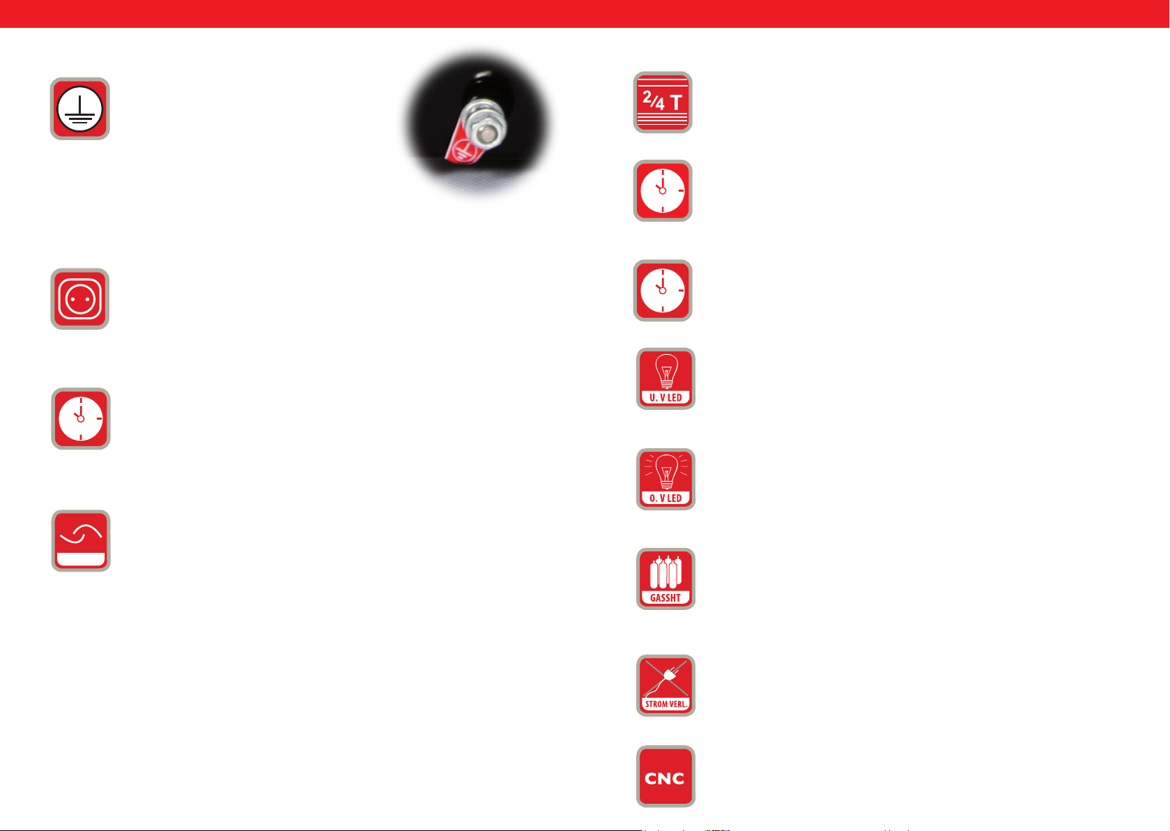
DEEN
DE
EN
9.
10.
11.
12.
Grounding: At the back of each welder there is
a screw and a label to provide the necessary
grounding. Before operating the unit it is
necessary to ground the shell of the welding
apparatus by means of a cable with not less than
6 mm diameter, in order to prevent potential
problems caused by electricity leakages.
Additional power supply connection to the plasma torch cable.
POST TIME = gas ow variable at second intervals. This regulation is
important for the cooling of the cut melted metal after the cutting
process and to protect against oxidation.
13.
4T/2T selection button
14.
POST FLOW = setting the time of the air ow after the cutting.
15.
TEST GAS = protection
16.
U.V LED = Under Voltage LED. This LED control light will turn on
when the voltage drops under 330 V.
17.
O.V LED = Over Voltage LED. This LED control light will turn on
when the voltage rises above 420V.
ROCKER SWITCH = If the cutter (the workpiece) is not in determined, automatically set position, button on the cutting torch should
SWITCH
74 75
be pressed in order to begin cutting. In order to nish cutting, button
on the torch should be released. Such cutting type is useful for short
seam. If the workpiece is in determined, automatically set position,
button on the torch should be pressed once in order to start the
plasma arc. Such action allows for uninterrupted cutting. Press the
button on the torch again to stop cutting. This cutting type is useful
for cutting longer seams.
Rev. 04.04.2022 Rev. 04.04.2022
18.
GASSHT = this control light will turn on when air ow is not available or is insufcient.
19.
PHASEN STROMVERLUST = this control light will turn on when
device is connected to 1 or 2 phases (instead of 3) – device stops
working.
20
CNC connection socket.
Page 39
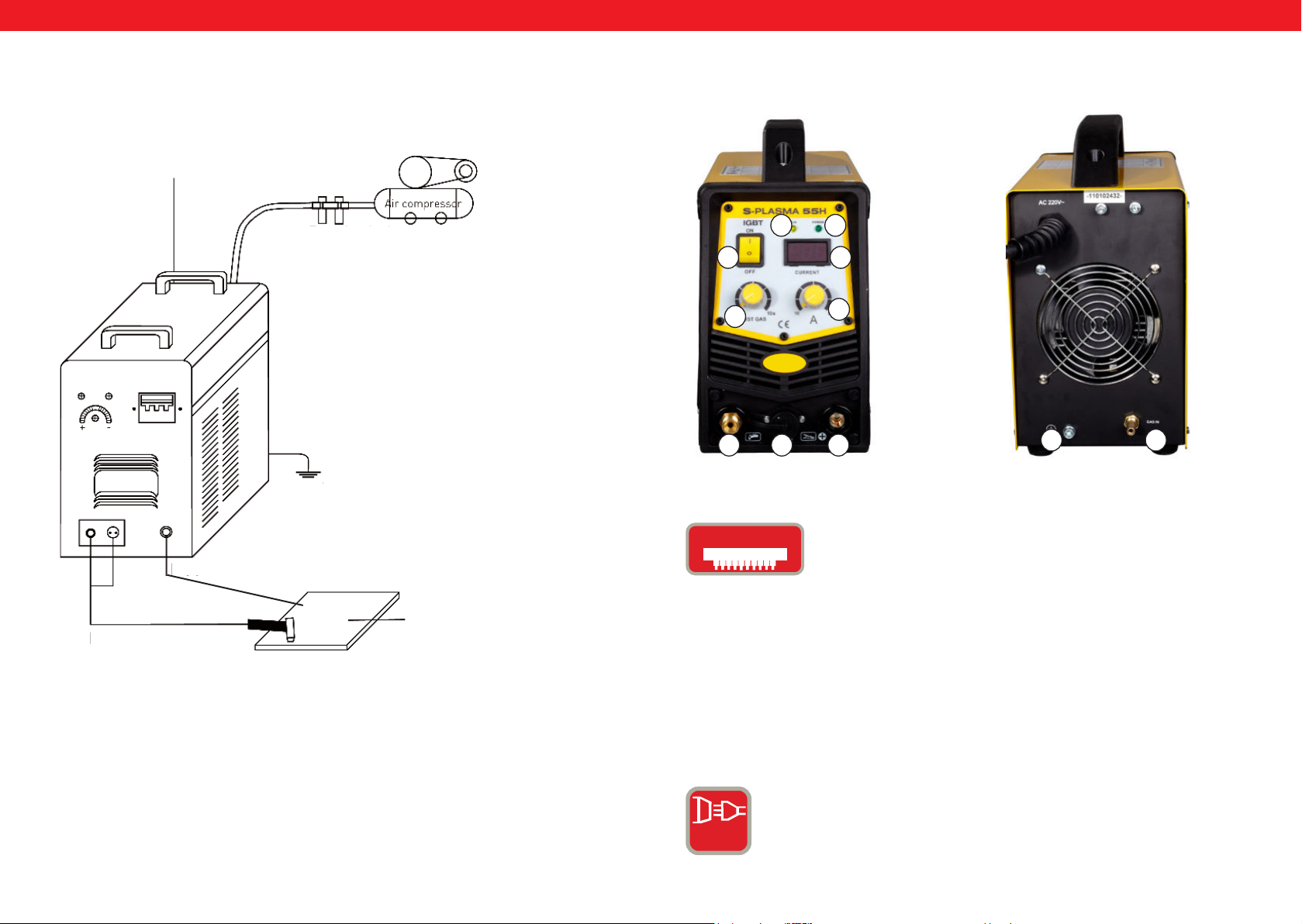
DEEN
DEEN
General diagram of S-Plasma 55H connection
Power supply cord
Pressure regulator
Cover earthing
Air compressor
S-PLASMA 55 H
FRONT VIEW
0
11
REAR VIEW
32
4
1
567
9 8
IGbT
Mass cable
Workpiece
Plasma cable
with torch
IGBT:
A bipolar transistor with insulated gate electrode (insulated
gate bipolar transistor, IGBT) is a semiconductor that
is increasingly used in power electronics, as the bipolar
transistors offer certain advantages (e.g. good forwarding
characteristics, high blocking voltage, robustness in welding
equipment) and benets characteristic of a eld effect
transistor (control with virtually no power consumption).
Another advantage is a certain degree of resistance to short
circuits, as IGBT limits the load current. IGBTs are a further
development step of the vertical power MOSFETs.
NORMAL CURRENT: The device uses a 1-phase connection
(230V +/- 10%).
1 PH
76 77
Rev. 04.04.2022 Rev. 04.04.2022
Page 40
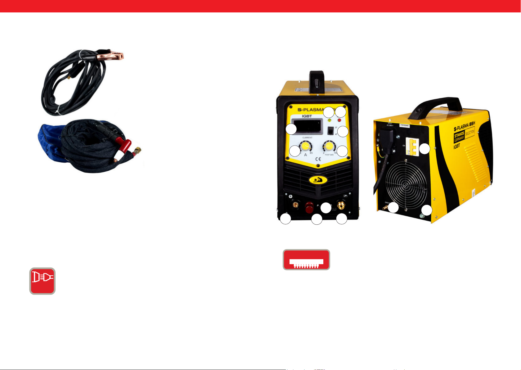
DEEN
DE
EN
Plasma cutters accessories
1
1. Grounding clamp cable
2. Plasma torch with cable
2
S-PLASMA 85H | S-PLASMA 85CNC
FRONT VIEW
19
2
4
1
12
11
REAR VIEW
0
20
5
20. Only for S-PLASMA 85CNC
POWER SUPPLY FOR S-PLASMA 85H / S-PLASMA 85CNC
STARKSTROM: = These devices use a 3-phase connection
(400V +/- 10%).
6
IGbT
3 PH
78 79
Rev. 04.04.2022 Rev. 04.04.2022
7
A bipolar transistor with insulated gate electrode (insulated
gate bipolar transistor, IGBT) is a semiconductor that
is increasingly used in power electronics, as the bipolar
transistors offer certain advantages (e.g. good forwarding
characteristics, high blocking voltage, robustness in welding
equipment) and benets characteristic of a eld effect
transistor (control with virtually no power consumption).
Another advantage is a certain degree of resistance to short
circuits, as IGBT limits the load current. IGBTs are a further
development step of the vertical power MOSFETs.
8
9
Page 41
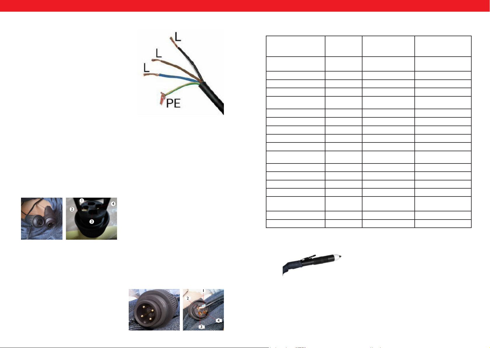
DE
PODŁĄCZENIE CNC
Aby podłączyć przecinarkę do maszyny CNC należy podłączyć dwa piny we
wtyczce: pin 3 oraz pin 4. CNC będzie działać w przypadku gdy maszyna CNC
będzie włączona, w przeciwnym przypadku będzie działało tylko cięcie ręczne.
Pin 1 oraz 2 są podłączone fabrycznie i jest to podłączenie tylko i wyłącznie do
cięcia ręcznego:
EN
DE
EN
S-Plasma 85H + 125H / 85CNC + 125CNC connection.
Power supply.
The yellow-green wire is used as a PE protective wire connector. The three phases (black,
brown and blue) can be freely connected to L1,
L2 and L3 (please have it done only by a quali-
ed electrician).
Warning!!!
Welding devices equipped with 3-phases connection cable can be connected only by
qualied electrician!
CNC CONNECTION: S-PLASMA 125CNC
In order to connect the plasma cutter to the CNC machine, the two pins in the plug
should be connected:
Pin 4: positive pole
Pin 2: negative pole
Detailed technical parameters:
S-Plasma
55H
Input voltage 230V
1-phase
Frequency 50Hz 50Hz 50Hz
Input current 16A 19 A 20 A
No load voltage 230 V 280 V 300 V
Degree of protection of
the housing
Insulation class F
Surge protection Ye s
Cooling Fan
Magnetic valve Ye s
Duty cycle ED at max. A
Value of Current for
Duty Cycle 100%
Cutting current 10-55 A 20-85 A 10-125 A
Arc ignition Contact Non-contact Non-contact
Cutting thickness 17 mm 27 mm 34 mm
Cutting width 1 mm 1,2 mm 1,4 mm
Compressor connection 4,5 bar,30-100
Net weight 9.4 kg 19,5 lg 30 kg
Dimensions L/W/H (mm) 530/380/380 660/370/450 660/370/450
IP20S
60%
42,6 65,8 96,8
1/min.
S-Plasma 85H
und
S-Plasma 85CNC*
400V
3-phases
IP20S IP21S
F F
Ye s Ye s
Fan Fan
Ye s Ye s
60% 60%
5,5 bar,
175 l/min.
S-Plasma 125H
und
S-Plasma 125CNC*
400V
3-phases
7 bar
250 l/min
NOTICE: S-Plasma 85CNC and S-Plasma 125CNC are equipped with additional CNC
connection socket. These two plasma cutters are also equipped with straight plasma
CNC CONNECTION: S-PLASMA 85CNC
torch:
In order to connect the plasma cutter to the CNC machine, the two pins in the plug
should be connected: pin 3 and pin 4. CNC function will work under condition that
CNC machine is on, otherwise, when CNC machine is off – manual cutting works. Pin
1 and pin 2 (with wiring connected already) are for manual cutting.
Pin 3: positive pole
Pin 4: negative pole
80 81
Rev. 04.04.2022 Rev. 04.04.2022
Page 42
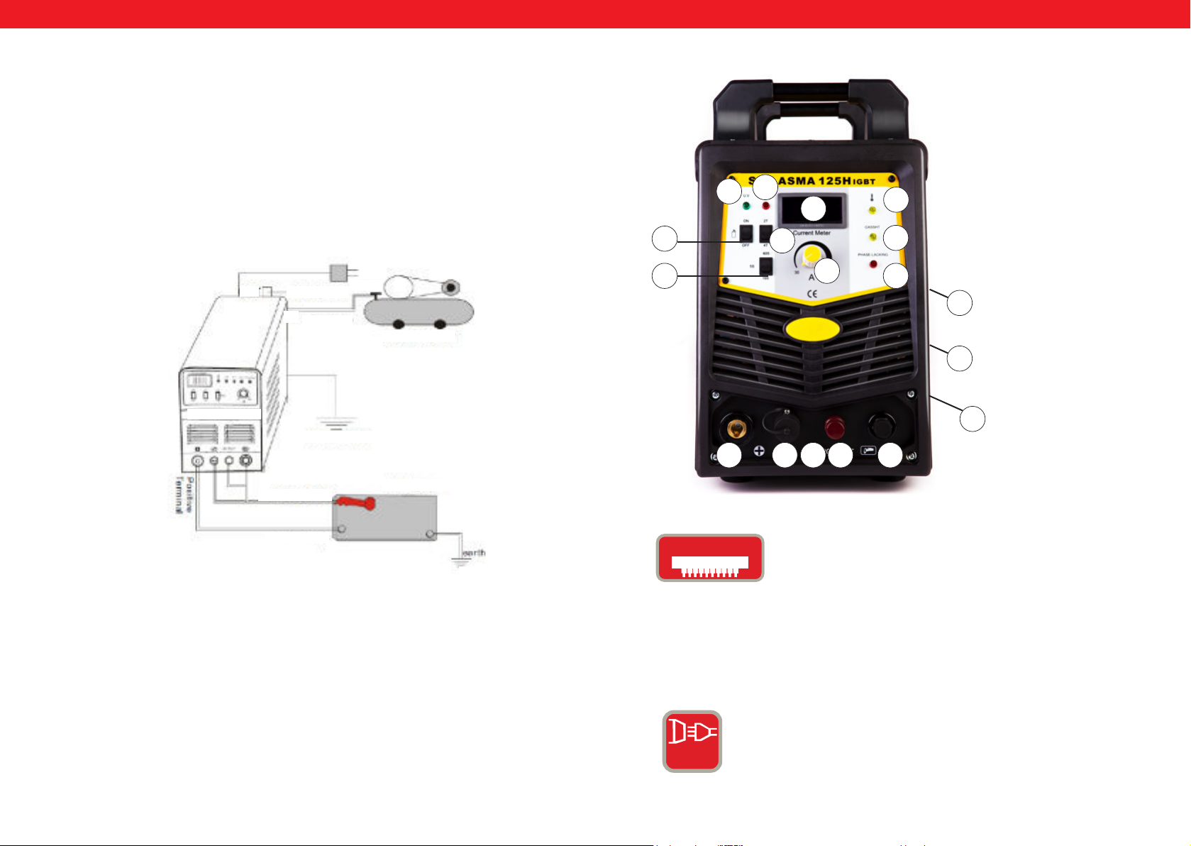
DEEN
DE
EN
Cable connections
1. Each plasma cutter is equipped with a main power cable, which is responsible for
providing current and voltage to the device and it must be connected to the suitable
power source according to plasma cutter input voltage.
2. The main power cable should be properly connected to the connection socket in order to avoid oxidation. If possible, check using the measuring instrument if the voltage
ts in the appropriate range.
Installation
Cable connections (the installation sketch)
400V
OUT
Compressed
air regulation
IN
Luftschlauch
Air compressor
S-Plasma 125H
Cover earthing
S-PLASMA 125H | S-PLASMA 125CNC
17
15
14
16
7
4
13
1
10 6 5
20
2
18
19
0
9
8
Plasma torch
Mass clamp
Operation
Turn on the switch at the back of the device, control light turns on and value of the
current (A) is visible.
Set the desired gas pressure and open the pressure valve.
Press the button on the cutting torch, valve turns on and arc can be seen and heard.
Set the cutting stream according to the workpiece thickness.
Place the cutting torch copper nozzle on the workpiece (in case of pilot arc, the copper nozzle should be placed about 2 mm above the workpiece), press the button on
the torch until the arc will be ignited, raise the cutting nozzle approx. 1 mm above the
workpiece and start cutting.
82 83
Workpiece
20. S-PLASMA 125CNC only.
Earthing
3 PH
Rev. 04.04.2022 Rev. 04.04.2022
IGbT
A bipolar transistor with insulated gate electrode (insulated
gate bipolar transistor, IGBT) is a semiconductor that
is increasingly used in power electronics, as the bipolar
transistors offer certain advantages (e.g. good forwarding
characteristics, high blocking voltage, robustness in welding
equipment) and benets characteristic of a eld effect
transistor (control with virtually no power consumption).
Another advantage is a certain degree of resistance to short
circuits, as IGBT limits the load current. IGBTs are a further
development step of the vertical power MOSFETs.
STARKSTROM: = These devices use a 3-phase connection
(400V +/- 10%).
Page 43
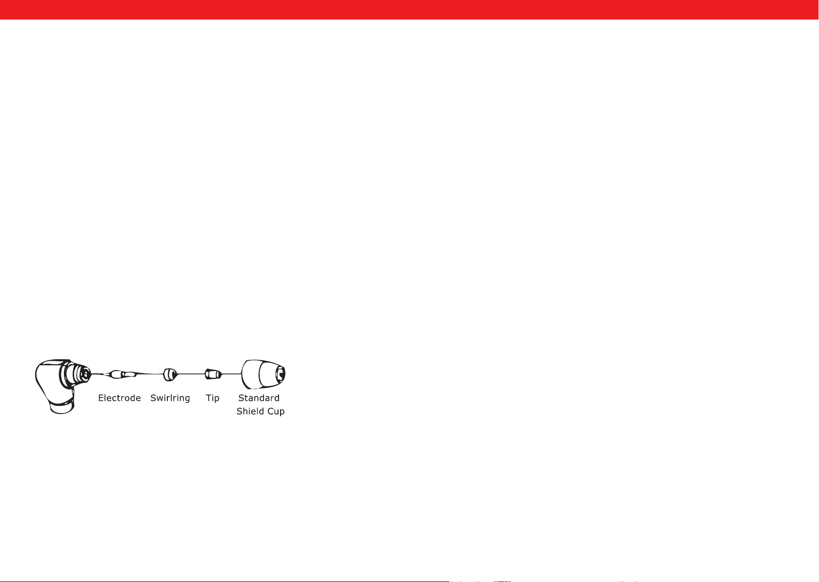
DEEN
DEEN
INITIATING OPERATION
A. Unpacking
Unpack all the items out of the box and make sure that you have received all items
listed on the packing list.
B. Work environment
Make sure that the work area is well ventilated. The unit is cooled by an axial fan that
provides an air ow for the electronics through the rear panel. (Note! The housing
must be installed in a way that ensures that the vent holes are closer to the front of the
machine). At least 15 cm at the front and 15 cm on each side should be left to enable
cleaning. If the machine is operated without adequate cooling, the length of the duty
cycle will be reduced greatly.
C. Cable connections
Each unit is equipped with a main power cable, which is responsible for providing current and voltage to the device. If the device is connected to power which exceeds the
required voltage, or if the wrong phase is set, it may lead to severe damage to the unit.
This is not covered by the warranty for the equipment and the user will be responsible
for such situations.
D. Torch connection
Connect the torch to the inverter by connecting the air tube that is attached at the
end of the torch to the torch connector on the front part of the machine. Ensure that
the connection is secure by tightening it slightly with a spanner. However you should
not make it too tight.
INSTRUCTIONS FOR USE
A. The beginning
Turn the power switch to „ON“. Take up a position at the unit in which you can easily
read the air pressure from the device. Press the pistol switch (air will ow out from the
pistol), adjust the air valve to approximately 6-7 (bar) and press the pistol switch again.
Note
The generally accepted value range of air pressure is 5-8 bar. You can now perform
tests as needed, but you should remember not to reduce the air pressure too much
because it may damage the consumables. Secure the grounding clamp on the workpiece. Connect the clamp to the main part of the workpiece and not to part which is to
be removed.
B. Cutting
1. Drag-cutting
Hold the tip of the pistol above the workpiece, press the pistol switch and move the pistol tip until it comes into contact with the workpiece and the cutting arc is established.
Once the cutting arc is generated you may move the pistol in the desired direction with
the tip of the pistol always at a slight angle and maintaining contact with the workpiece.
This working method is called drag cutting. Excessively rapid movements should be
avoided. A sign of this are sparks, which can spray from the top of the workpiece. Move
the pistol with a speed that ensures gathering of the sparks under the workpiece and
before proceeding make sure that the material is cut through completely. Set the drag
speed as required.
Pilot Assembly
A. Assembling the pistol
Put the pistol the protective cap facing up and turn the cap away from the gun. (The
protective cap holds the tip, the ceramic swirl ring and the electrode together). Remove the cap, the ceramic swirl ring and the electrode. Assemble the electrode, the
ceramic swirl ring and the tip back together. Replace worn parts if necessary. Put the
protective cap on the head of the pistol and screw it on with your hand until it is snug.
If any resistance is present during this process, check the thread and the arrangement
of the items before resuming work. Note: In case of some pistols with no reversible
electrodes it is necessary to tighten the electrode further by using a pair of pliers in
order to ensure a reliable electrical connection.
84 85
Rev. 04.04.2022 Rev. 04.04.2022
84
2. Weekly activities
Verify the proper operation of the air ow. Blow off or suck in dust or dirt from the
entire machine, including the air lter.
3. Distance cutting
In some cases it may be advantageous to perform cutting with the tip of the pistol at
a height of approximately 1/16“ to 1/8“ above the workpiece in order to reduce the
amount of material which is once again blown back into the tip and to maximize the
penetration of thick cuts through the material. Distance cutting should be used when
penetration cutting or or grooving is executed. The distance technique may also be
used when cutting sheet metal in order to minimize the risk of material back splashing,
which could damage the tip.
4. Drilling through
In order to drill through the tip of the pistol should be placed at approximately 3,2 mm
above the workpiece. Hold the pistol at a slight angle to deect the sparks away from
yourself and the tip of the pistol. Activate the main arc and lower the tip of the pistol
until the main cutting arc is initiated and sparking begins. Initiate drilling on a test item
which is no longer in use and continue with the drilling on the previously dened cut
line once the test hole is completed without problems.
Page 44

DEEN
MAINTENANCE
Check the pistol for wear damage, cracks or exposed wire sections. Replace or repair
any such defects before using the device. A heavily worn pistol tip/nozzle contributes
to the reduction of speed, voltage drops and crooked cuts. An indication of a worn
pistol tip/nozzle is an elongated or oversized nozzle opening. The external part of the
electrode may be recessed no more than 3.2 mm. Replace the electrode if it is worn,
as indicated by the above measurement. If the cap cannot be reattached easily, check
the thread.
WARNING!!! Always turn off the device when replacing the electrodes and nozzles.
Inspection
1. Device should always be grounded in safe way.
2. Always check if all terminals are properly connected.
3. Check if the power cable leads the correct voltage.
4. Pay attention at the cables and hoses – they should not be damaged or worn.
MANUAL DE INSTRUCCIONES
S-PLASMA 55H | S-PLASMA 85H
S-PLASMA 125H | S-PLASMA 85CNC
S-PLASMA 125CNC
86
Rev. 04.04.2022
expondo.de
87
Page 45

ES
ES
Este manual de usuario contiene instrucciones de funcionamiento e información
fundamental sobre el mantenimiento de los cortadores de plasma S-Plasma
555H/85H/125H de Stamos Germany. Solo una correcta comprensión de las
características y posibilidades de uso garantiza un uso adecuado.
ATENCIÓN
• Garantice su seguridad y proteja a terceras personas de lesiones. Lea este manual
con detenimiento y respete las medidas de seguridad.
• La instalación y mantenimiento del equipo deben de ser realizados únicamente por
personal cualicado.
• Durante la utilización de este dispositivo, mantenga a terceras personas,
particularmente los niños, alejados del lugar del trabajo.
El proceso de corte por plasma puede ocasionar incendios o explosiones.
El arco del plasma desprende chispas y trozos de metal candente. Estas salpicaduras
del arco, así como el calor que se desprende de la pieza de trabajo y los componentes
del equipo pueden provocar fuego y quemaduras. Retire de la zona de trabajo todos
los objetos que representen un riesgo de incendio.
• Mantenga todo material inamable a un radio mínimo de 10,7 m del equipo.
• Si esto no es posible, tápelo para impedir que las chispas del corte provoquen un
incendio.
• Evite realizar trabajos de corte cerca de atmósferas inamables.
• Protéjase y proteja a terceros contra chispas y salpicaduras de metal.
• Recuerde que las chispas del arco de plasma y las salpicaduras de materiales calientes pueden introducirse con facilidad por pequeñas ranuras o grietas de las
zonas adyacentes.
• Tenga un extintor siempre a mano.
• Tenga en cuenta que cuando corte al plasma en un techo, suelo o pared puede originar fuego en otro lado (lado no visible).
No lleve a cabo trabajos de corte o corte o soldadura en envases cerrados como p.ej.: tanques o barriles.
Conecte el equipo al enchufe más próximo para evitar que los cables eléctricos queden
extendido sobre una supercie que no sea ignífuga o pueda provocar una descarga
eléctrica.
• No utilice el cortador de plasma para descongelar tuberías.
• Evite soldar contenedores que puedan encerrar materiales inamables. Asegúrese
de vaciar y limpiar estos recipientes en profundidad antes de proceder con el trabajo.
• Evite cortar en estancias que puedan contener partículas de polvo o vapores ex-
plosivos.
• No corte cilindros, tuberías o recipientes que estén bajo presión.
• Evite cortar al plasma contenedores que hayan contenido materiales inamables.
• Utilice prendas de protección apropiadas, sin aceite, tales como guantes de cuero,
camisas gruesas, pantalones sin remangar, zapatos de caña alta y una gorra sobre su
cabeza.
• No trabaje sobre supercies inamables.
• Antes de empezar a soldar, deshágase de todos los objetos consumibles que lleve
encima, tales como mecheros de gas o cerillas.
• Siga las instrucciones en materia de prevención de incendios y mantenga siempre
un extintor a mano. Evite tocar piezas eléctricas con tensión pues pueden causarle
una descarga fatal o quemaduras graves.El circuito del electrodo y la pieza siempre
está con tensión cuando la salida está encendida.El circuito de alimentación y los
circuitos internos de la máquina también tienen tensión cuando la alimentación está
encendida.
El corte por plasma requiere un mayor voltaje para cebar y mantener el arco que
el proceso de corte o soldadura (generalmente 200 - 400 V). Este cortador incluye
una antorcha equipada de un mecanismo de seguridad, que apaga el dispositivo si se
desprende la boquillla o el electrodo entra en contacto con la boquilla. Todo equipo
que esté instalado o conectado a tierra de manera incorrecta constituye un peligro.
LA DESCARGA ELÉCTRICA PUEDE OCASIONAR LA MUERTE
• No toque partes eléctricas con tensión.
• Use guantes y ropa de protección aislante, seca y sin agujeros.
• Aíslese usted mismo de la pieza y del suelo mediante el uso de alfombras o cubiertas aislantes secas.
• Evite tocar la antorcha cuando entre en contacto con la pieza de trabajo o el suelo.
• Antes de instalar o realizar tareas de mantenimiento de la antorcha, desconecte la
alimentación.
88 89
Rev. 04.04.2022 Rev. 04.04.2022
Page 46

ES
ES
• Asegúrese de que el equipo está desconectado del suministro eléctrico antes proceder con tareas de instalación o mantenimiento.
• Compruebe y cerciórese de que el equipo esté conectado a un enchufe con una
correcta toma de tierra.
• Compruebe siempre la toma de tierra.
• Antes de encender el equipo, añada un conector a tierra adecuado.
• Verique regularmente el estado de los cables de cara a posibles daños o partes mal
aisladas. En caso de detectar algún desperfecto, sustituya el cable inmediatamente,
ya que un cable mal aislado puede provocar una descarga mortal.
• Apague el equipo, si no se utiliza.
• Examine los cables y sustitúyalos en caso de que estén dañados o presenten un
acusado desgaste.
• Evite envolver los cables al rededor de su cuerpo.
• Conecte la pieza a una buena puesta a tierra eléctrica.
• Utilice siempre une equipamiento en buenas condiciones.
• Repare o sustituya inmediatamente los componentes dañados.
• Cuando trabaje en altura utilice un arnés de seguridad para evitar las caídas.
• Mantenga todos los paneles y cubiertas en su lugar.
• Manténgase alejado de la punta de la antorcha y el arco eléctrico en cuanto haya
pulsado el gatillo.
• Conecte el cable de masa una parte metálica de la pieza (evite conectarlo si la pieza
corre el riesgo de caerse) o a un banco, lo más cerca posible al equipo.
• Aísle la pinza de tierra cuando no esté conectada a la pieza de trabajo para evitar un
contacto accidental con otro metal.
EL EQUIPO TIENE UNA IMPORTANTE CARGA DE CORRIENTE
CONTINUA TRAS SU DESCONEXIÓN DE LA CORRIENTE
Antes de tocar cualquier componente del equipo, apáguelo, desenchúfelo de la corriente y compruebe la que la tensión en el condensador de entrada esté casi a cero.
Antes de realizar tareas de mantenimiento, asegúrese de revisar los condensadores de
acuerdo a las instrucciones detalladas en el capítulo de mantenimiento de este manual.
La explosión de las piezas puede causar graves lesiones.
Chispas y salpicaduras salen despedidas del arco de corte.
Las chispas de corte o corte o soldadura pueden provocar daños personales.
• Utilice siempre una máscara de soldadura o gafas de seguridad con protecciones
laterales.
• Utilice ropa de trabajo apropiada para proteger su piel.
• Utilice siempre tapones u otro tipo de protección auditiva para evitar que las chi-
spas se cuelen en los oídos.
• Los rayos del arco de corte o soldadura emiten un intenso calor y fuertes rayos
ultravioletas que pueden quemar los ojos y la piel.
Los rayos del arco pueden provocar quemaduras en la piel y los ojos.
• Use una careta de protección provista de una tonalidad de ltro adecuada para pro-
teger su cara y ojos cuando realice u observe trabajos de corte al arco de plasma.
• Las normas de seguridad recomiendan una tonalidad Nr. 9 (Nr. 8 como mínimo)
para todos los procesos de corte inferiores a los 300 amperios. Tonalidades inferiores se pueden utilizar solo si el arco eléctrico está oculto.
• Utilice siempre gafas de seguridad con protecciones laterales o una máscara de
corte o soldadura.
• Proteja al personal que se encuentre en las inmediaciones con una pantalla de pro-
tección no inamable y/o adviértales que no miren directamente al arco ni que se
expongan a radiaciones o a salpicaduras incandescentes.
• Para proteger su piel y la de sus ayudantes frente a los rayos o proyecciones del
arco, utilice la ropa de trabajo apropiada confeccionada de un material resistente e
ignífugo, así como zapatos de seguridad.
Una descarga eléctrica puede resultar mortal.
El convertidor de corriente contiene piezas que pueden explotar cuando el equipo está
conectado a la corriente. Por ello, utilice siempre una pantalla de protección y camisa
de manga larga, cuando opere el convertidor.
90 91
Rev. 04.04.2022 Rev. 04.04.2022
Page 47
ES ES
PLASMA
Informaciones generales sobre el plasma: Los equipos de corte por plasma funcionan
aplicando gas bajo presión (aire comprimido, p.ej.), expulsado por un pequeño tubo, el
cual tiene un electrodo en el centro y una boquilla en su extremo. La compresión concentra extraordinariamente la energía cinética del gas empleado. Cuando se suministra
corriente al electrodo con carga negativa y la punta de la boquilla entra en contacto
con la pieza metálica, se crea un circuito que generará una potente chispa de ignición.
Esta chispa calienta el gas que uye a través de la boquilla y dirige una corriente de
plasma de aprox. 16.649º C a una velocidad de 6,096 m/s sobre la pieza de trabajo, lo
que convierte el metal en vapor y residuos fundidos. El plasma transmite corriente
eléctrica. El arco seguirá encendido mientras se suministre corriente al electrodo y el
plasma esté en contacto con la pieza metálica. La boquilla de corte incorpora canales
adicionales que liberan un constante ujo de gas protector, que permite regular el radio
del caudal de plasma.
NOTA: ¡Advertencia! Esta máquina está concebida para trabajar solo con aire comprimido.
REGULACIÓN DE LA CORRIENTE
El circuito automático de baja presión protege contra la sobretensión hasta el valor
máximo indicado en la hoja de datos técnicos.
PROTECCIÓN TÉRMICA
LEYENDA
0.
On
Off
1.
2.
INTERRUPTOR ON/OFF
Regulador de la corriente:
CURRENT = amperaje regulable
PILOTO DE SOBRECARGA TÉRMICA / AVERÍA
Este piloto se enciende en cualquiera de las dos siguientes situaciones:
a) Cuando la máquina no funciona correctamente y no se puede
poner en marcha.
b) Cuando el equipo de corte o corte o soldadura sobrepasa
la duración normal de carga, se inicia el modo protección y la
máquina deja de funcionar; es decir, después de que el aparato se ha
sobrecalentado, se apaga progresivamente para reducir la temperatura.
El circuito de protección térmica se pone en marcha en cuanto el equipo rebasa el ciclo
de trabajo, lo que conlleva la parada de la máquina.
CICLO DE TRABAJO
El rendimiento del equipo viene especicado en base al „ciclo de trabajo“ (ED%), es
decir, la relación entre el tiempo de trabajo y de enfriamiento. Este factor puede variar
en el mismo equipo, dependiendo de las condiciones de trabajo que utilice (amperaje).
Este valor indica cuanto tiempo puede trabajar el equipo con la corriente seleccionada
y se mide de 10 minutos. Con un ciclo de trabajo del 60% el equipo puede trabajar de
manera continua durante 6 minutos, seguido de una pausa para que los componentes
del equipo se enfríen y se active la protección contra sobrecarga térmica. Exceder el
ciclo de trabajo de forma continuada puede provocar serios daños en el equipo.
92 93
Rev. 04.04.2022 Rev. 04.04.2022
Page 48
ES ES
3.
4.
5.+6.
7.
INDICADOR DE ENCENDIDO = Este piloto se ilumina cuando se
enciende la máquina
Pantalla – LED: muestra el amperaje actual.
muestra el amperaje actual.
CONEXIONES PARA LA ANTORCHA
La fuerte corriente del arco de plasma permite una alta velocidad
de corte, así como una excelente calidad de corte. No es necesario
un caro gas especial. El uso de aire comprimido y un sencillo manejo
le permiten un uso adecuado en la construcción de carrocerías,
contenedores, construcciones metálicas, así como en el sector de la
instalación de aire acondicionado y el área sanitaria.
9.
10.
11.
TOMA DE TIERRA
En la parte trasera del equipo se encuentra un
tornillo con la marca de tierra. Antes del uso es
necesario conectar el equipo a tierra a través de
un cable, cuya sección sea de al menos 6 mm2.
Antes de encender el equipo y para evitar
problemas con el ujo electricidad es necesario
conectar la toma de tierra con la carcasa del equipo
de soldar, a través de un cable cuyo diámetro no sea menor de 6
milímetros.
Conexión para la antorcha del cortador de plasma.
POST TIME (POST FLUJO DE GAS) = El ujo del gas protector se
puede regular en intervalos medibles en segundos. Esta regulación es
importante para enfriar el metal fundido después del proceso de corte
o corte o soldadura y protegerlo contra la corrosión.
Conexión del cable de tierra
8.
GAS
Conexión de GAS/ aire
AIR
94 95
Rev. 04.04.2022 Rev. 04.04.2022
12.
SWITCH
INTERRUPTOR ROCKER = Si la pieza a cortar está no está ja, presione de forma continuada el interruptor de la antorcha, para proce-
der con el corte. Para acabar con el corte deje de presionar el botón.
Este tipo de corte por plasma es adecuado para cortes pequeños.
Si la pieza a cortar está ja, presione el interruptor en la antorcha
una vez para encender el arco eléctrico. De esta forma usted puede
cortar de forma ininterrumpida.
Presione el interruptor otra vez, para parar con el corte. Este tipo de
cortes es apropiado para procesos prolongados.
Page 49
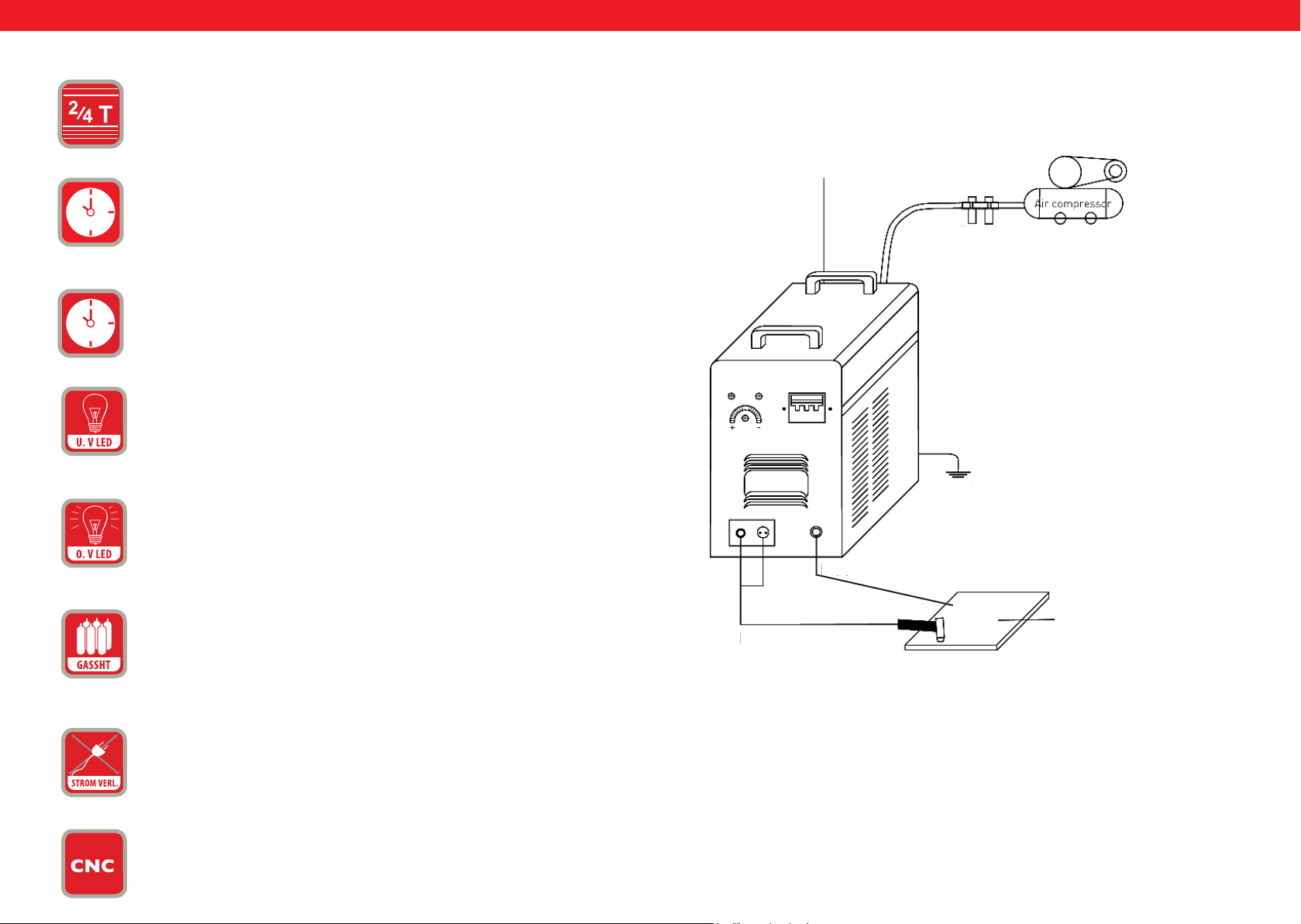
ES ES
13.
14.
15.
16.
17.
INTERRUPTOR „2T/4T“: Selección del modo de 2 o 4 tiempos. Corte
o soldadura TIG en modo de 2T (sin bloqueo) y 4T (con bloqueo).
POST GAS = Con este botón podrá regular el post - ujo de gas.
TEST GAS
LED U.V = Piloto de voltaje bajo. Se enciende si la tensión baja de los
330V
O.V LED = Piloto de voltaje alto. Este piloto se enciende si la tensión
supera los 420V.
ESQUEMA DE CONEXIÓN DE LA CORTADORA 55H
Cable de conexión
Compresor de aire
Manorreductor
del compresor
Seguridad de la carcasa
Cable de masa
18.
GASSHT = Este piloto se enciende si la máquina no dispone de suciente gas para operar.
19.
PERDIDA DE CORRIENTE = Este piloto se enciende si alguna de las
tres fases del equipo no están conectadas, parando el dispositivo.
20
Conexión CNC
96 97
Rev. 04.04.2022 Rev. 04.04.2022
Antorcha de
Piezade
Page 50
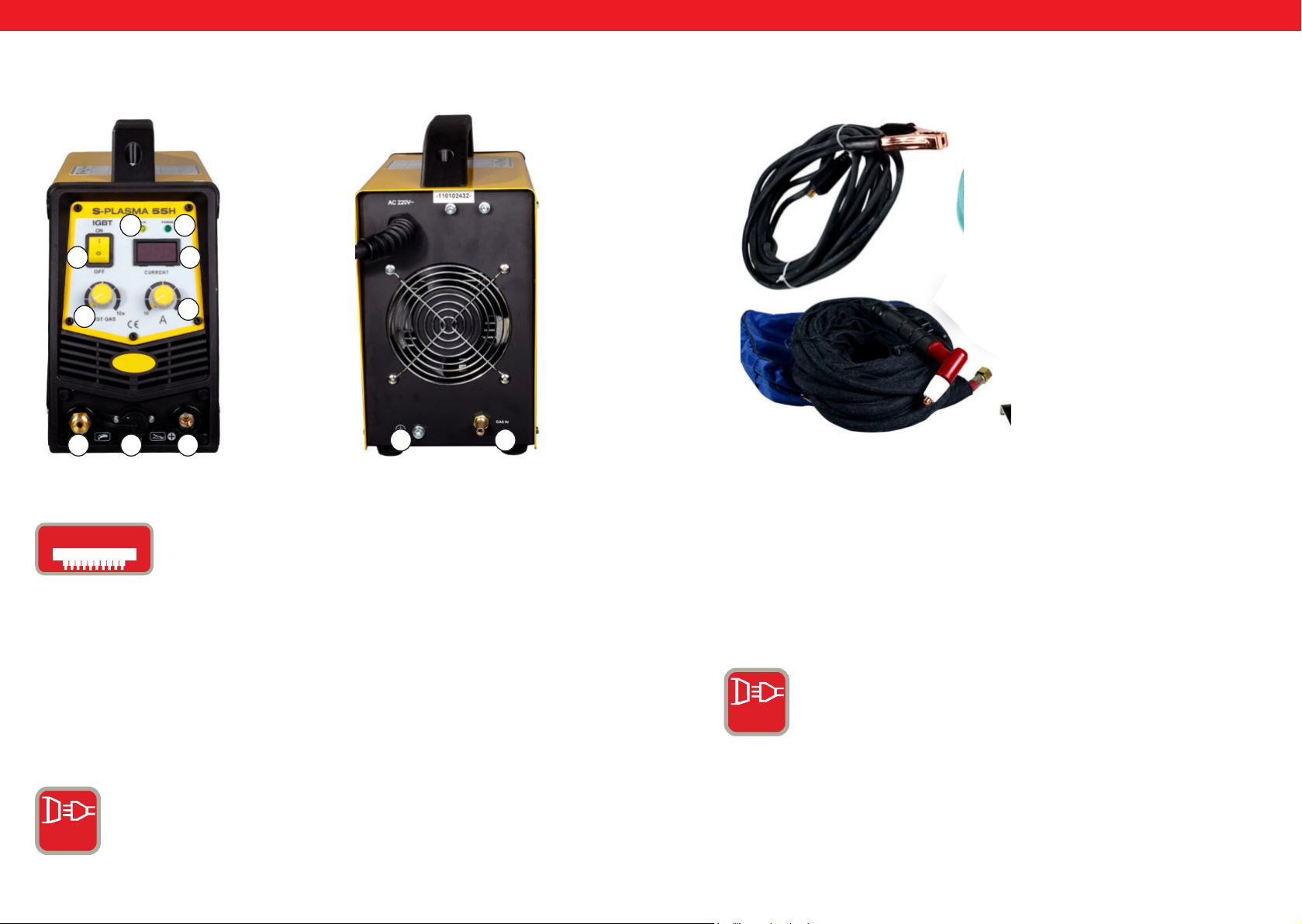
ES ES
S-PLASMA 55 H
VISTA FRONTAL
0
11
Accesorios para el corte de plasma
VISTA TRASERA
1
32
4
1
567
9 8
2
1. Pinza de tierra
2. Antorcha de
IGbT
IGBT = Un transistor bipolar con electrodo de puerta aislado
es un componente semiconductor, que se utiliza cada vez más
en la electrónica avanzada, ya que combina las ventajas del
transistor bipolar (p.ej. una buena capacidad de conducción,
alta tensión de bloqueo, robustez de los equipos de soldar)
y de un transistor de efecto de campo (consumo muy bajo en
CONEXIÓN PARA S-PLASMA 85H/S-PLASMA 85CNC
modo estático).
Otra ventaja de estos transistores es su protección contra
cortocircuitos, ya que el IBGT limita el paso de corriente. La
tecnología IBGT es un desarrollo de la MOSFET.
ENCHUFE TRIFÀSICO = Este equipo trabaja con un
enchufe trifásico (380 V)
3 PH
ELECTRICIDAD NORMAL = El equipo funciona con una
toma de corriente monofase (220V).
1 PH
98 99
Rev. 04.04.2022 Rev. 04.04.2022
Page 51
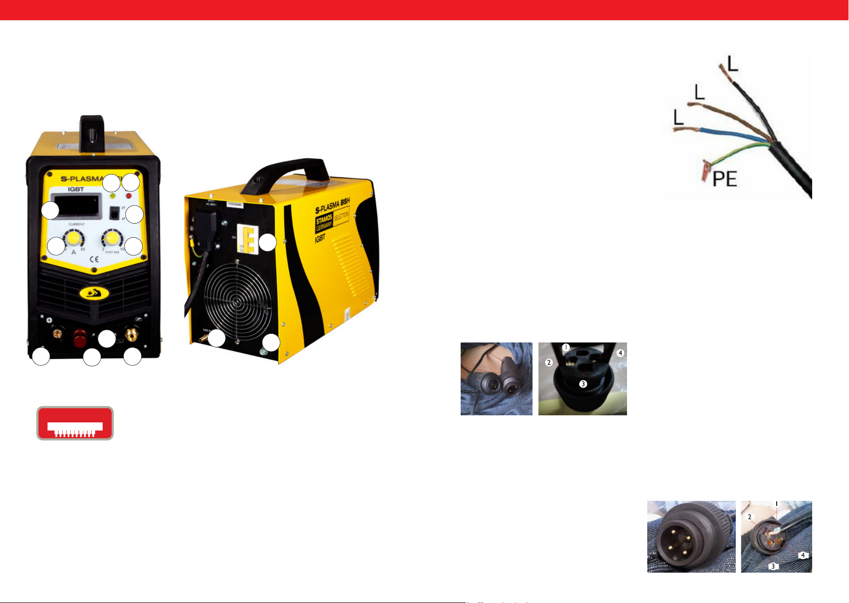
PODŁĄCZENIE CNC
Aby podłączyć przecinarkę do maszyny CNC należy podłączyć dwa piny we
wtyczce: pin 3 oraz pin 4. CNC będzie działać w przypadku gdy maszyna CNC
będzie włączona, w przeciwnym przypadku będzie działało tylko cięcie ręczne.
Pin 1 oraz 2 są podłączone fabrycznie i jest to podłączenie tylko i wyłącznie do
cięcia ręcznego:
ES ES
S-PLASMA 85H | S-PLASMA 85CNC
VISTA FRONTAL
19
2
4
1
12
11
VISTA TRASERA
0
Conexión del S-Plasma 85H + 125H / 85CNC + 125CNC
Conexión a la corriente eléctrica:
El cable amarillo/verde está previsto para la
conexión a tierra PE. Las tres fases se pueden conectar a cualquiera de las tomas L1, L2
o L3.Por favor, deje que esta tarea la realice un
electricista cualicado.
¡ATENCIÓN!
¡La conexión de dispositivos con tomas trifásicas solo puede ser llevada a cabo por
un electricista cualicado!
CONEXIÓN CNC DEL S-PLASMA 125CNC
Para conectar el cortador de plasma a la máquina CNC tienen que estar los enchufes
acoplados.
Enchufe 4: Polo positivo Enchufe 2: Polo negativo
20
5
20. Solo para el modelo S-PLASMA 85CNC
6
IGbT
100 101
7
IGBT =Un transistor bipolar con electrodo de puerta aislado
es un componente semiconductor, que se utiliza cada vez más
en la electrónica avanzada, ya que combina las ventajas del
transistor bipolar (p.ej. una buena capacidad de conducción,
alta tensión de bloqueo, robustez de los equipos de soldar)
y de un transistor de efecto de campo (consumo muy bajo en
modo estático).
Otra ventaja de estos transistores es su protección contra
cortocircuitos, ya que el IBGT limita el paso de corriente. La
tecnología IBGT es un desarrollo de la MOSFET.
8
9
Rev. 04.04.2022 Rev. 04.04.2022
CONEXIÓN CNC DEL S-PLASMA 85CNC
Para conectar el cortador de plasma a la máquina CNC tienen que estar los pines 3
y 4 de los enchufes acoplados.Si la máquina CNC está apagada, el equipo funcionará
solo con corte manual.
Pin 3: Polo positivo
Pin 4: Polo negativo
Page 52
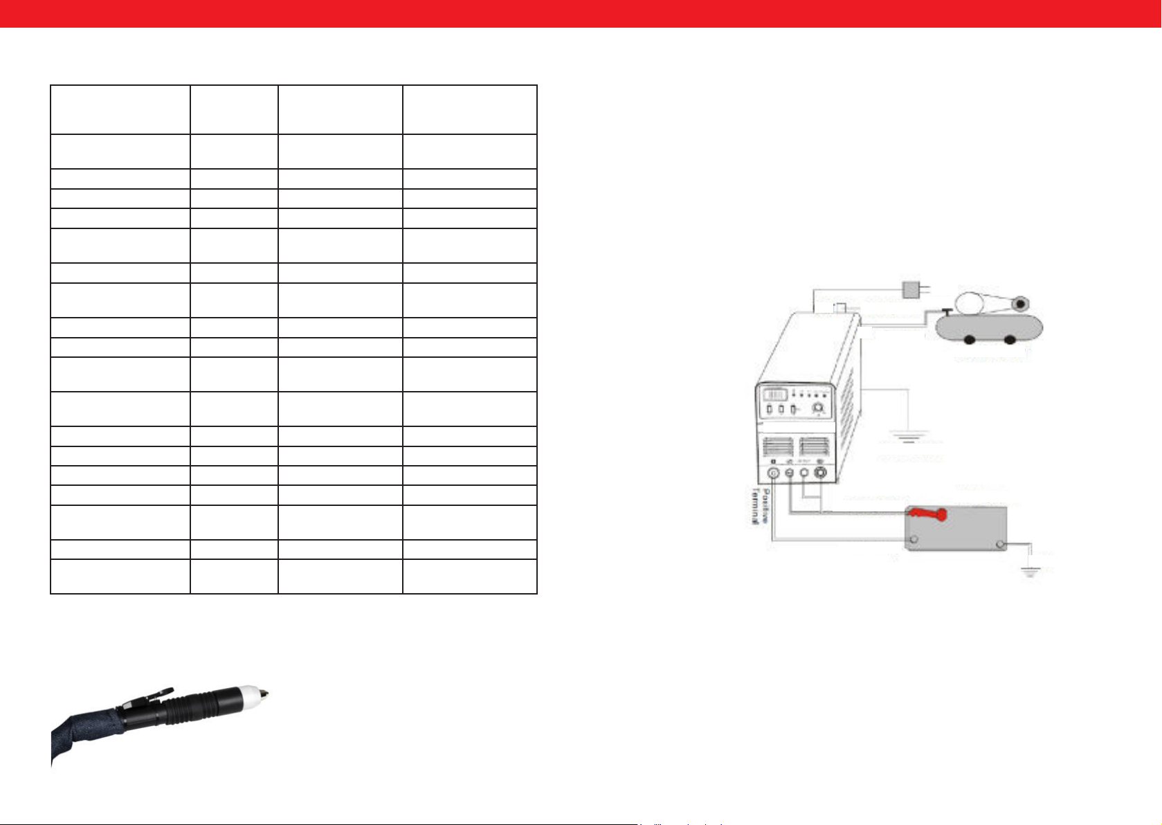
ES ES
Detalles técnicos
S-Plasma
55H
Voltaje de entrada 220V
(monofase)
Frecuencia 50Hz 50Hz 50Hz
Corriente de entrada 16A 19 A 20 A
Tensión en vacio 230 V 280 V 300 V
Tipo de protección de la
carcasa
Clase de aislamiento F F F
Protección contra sobretensión
Refrigeración Ventilador Ventilador Ventilador
Válvula eléctrica Sí Sí Sí
Ciclo de trabajo ED má-
ximo amperaje A (%)
Amperaje con 100% del
ciclo de trabajo
Corriente de corte 10-55 A 20-85 A 10-125 A
Ignición Contacto No - Contacto No - Contacto
Profundidad de corte 17 mm 27 mm 34 mm
Ancho de corte 1 mm 1,2 mm 1,4 mm
Conexión del compresor 4,5 bar,30-100
Peso neto 9.4 kg 19,5 kg 30 kg
Dimensiones LxAxA
(mm)
IP20S IP20S IP21S
Sí Sí Sí
60% 60% 60%
42,6 65,8 96,8
1/min.
530/380/380 660/370/450 660/370/450
S-Plasma 85H
und
S-Plasma 85CNC*
380V
(trifase)
5,5 bar,
175 l/min.
S-Plasma 125H
und
S-Plasma 125CNC*
380V
(trifase)
7 bar
250 l/min
Instalación
1. Los cortadores de plasma están equipados con un cable de alimentación, que
hay que conectar a la toma correspondiente al voltaje de entrada.
2. El cable de alimentación debe de estar bien conectado al enchufe para prevenir óxido. Si fuese posible, compruebe con un medidor que la tensión está en el
valor correspondiente.
Conexión de los cables de alimentación (diagrama de conexión)
380V
Compresor de aire
SALIDA
ENTRADA
S-Plasma 125H
Regulador de la
presión de aire:
Manguera de aire
Toma a tierra
Antorcha de corte
Pieza de trabajo
Pinza de tierra
Toma de tierra
Atención: Los modelos S-Plasma 85CNC y 125CNC están equipados con una toma
CNC adicional, así como una antorcha de corte plasma.
102 103
Rev. 04.04.2022 Rev. 04.04.2022
Page 53
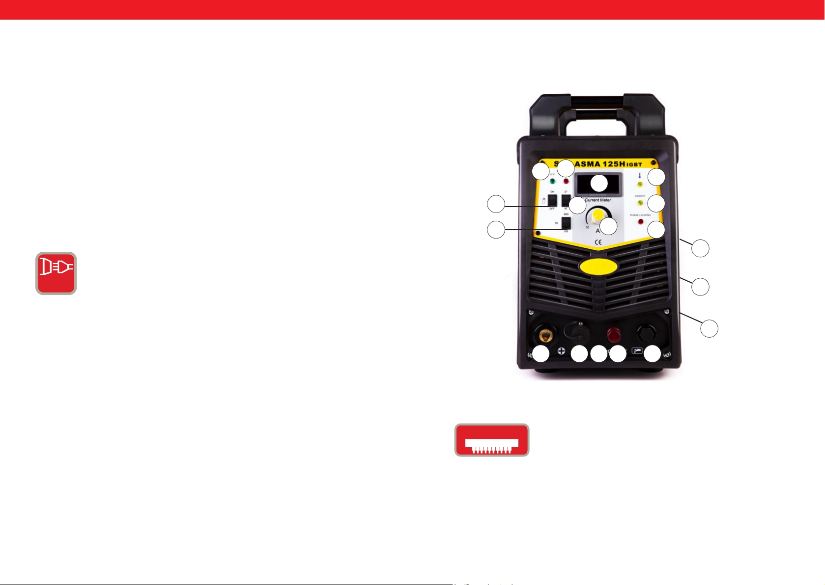
ES ES
Instrucción
Encienda el interruptor en el panel posterior del equipo, el piloto de control se
encenderá y se mostrará el amperaje en la pantalla.
Ajuste la presión en base a sus necesidades y abra la válvula de compresión.
Presione el botón de la antorcha para activar la válvula. Podrá oir y ver el arco de
corte.
Ajuste el amperaje de corte según el grosor del material a trabajar.
Aproxime la boquilla de cobre a aproximadamente 2 mm de la pieza de trabajo
y pulse el gatillo de la antorcha hasta que el arco se encienda. A continuación
mantenga la punta de la boquilla a 1 mm del material y puede empezar a cortar.
3 PH
NCHUFE TRIFÀSICO Este equipo trabaja con un enchufe
trifásico (380 V)
S-PLASMA 125H | S-PLASMA 125CNC
17
16
4
15
14
13
1
2
18
19
0
9
8
7
20. Solamente para el modelo S-PLASMA 125CNC
IGbT
104 105
Rev. 04.04.2022 Rev. 04.04.2022
IGBT =Un transistor bipolar con electrodo de puerta aislado
es un componente semiconductor, que se utiliza cada vez
más en la electrónica avanzada, ya que combina las ventajas
del transistor bipolar (p.ej.: buena capacidad de conducción,
alta tensión de bloqueo, robustez de los equipos de soldar)
y de un transistor de efecto de campo (consumo muy bajo en
modo estático).
Otra ventaja de estos transistores es su protección contra
cortocircuitos, ya que el IBGT limita el paso de corriente. La
tecnología IBGT es un desarrollo de la MOSFET.
10 6 5
20
Page 54
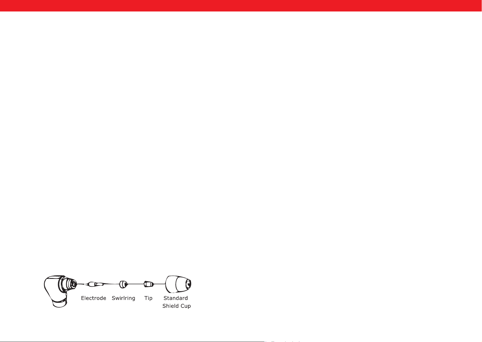
ES ES
INSTALACIÓN
A. Desempaquetado
Saque todo lo que contiene el paquete y asegúrese de que ha recibido todos los componentes que se enumeran en la lista de embalaje.
B. Entorno de trabajo
Garantice siempre una estancia de trabajo con buena ventilación. El equipo se enfría
mediante un ventilador axial, que toma el ujo de aire por la parte posterior.
NOTA: La carcasa debe montarse con los oricios de ventilación próximos al frontal
del equipo. Deje por lo menos 15 cm de separación por la parte posterior y lateral, ya
que una ventilación insuciente del aparato reduce el ciclo de trabajo de una manera
importante.
C. Conexión de los cables
Todos los equipos disponen de un cable principal de corriente para garantizar el sumi-
nistro de corriente y tensión en el dispositivo. Cuando el equipo está conectado a la
corriente con una tensión mayor a la necesaria o con una fase mal conectada, el equipo
puede resultar dañado. Este tipo de daños no están cubiertos por la garantía, sino que
son responsabilidad del usuario. Este tipo de daños no están cubiertos por la garantía,
sino que corren por cuenta propia del usuario.
D. Conexión de la antorcha
Conecte la antorcha con el equipo de manera que el tubito de aire al nal de la manguera de la antorcha está enroscado a la toma en la parte del frontal del dispositivo.
Asegure esta conexión con un destornillador, sin apretar en exceso.
A. Proceso de la construcción de pistola
Coloque la antorcha con el tapón mirando hacia arriba y gírelo. (el tapón sujeta la punta, el anillo cerámico y el electrodo).
Retire la punta, el anillo cerámico y el electrodo. Vuelva a montar el electrodo, el anillo
de cerámica y la punta de nuevo. Sustituya las piezas que presenten desgaste. Monte el
tapón protector de nuevo en la punta de la antorcha y enrósquelo con la mano hasta
que esté rme. Cuando note resistencia en este proceso, compruebe el estado de la
rosca y el orden de los componentes anteriores.
Nota:
En algunas antorchas, cuyos electrodos no se pueden cambiar es necesario apretar el
electrodo, utilizando unas tenazas, para garantizar una óptima conexión eléctrica.
USO
A. El principio
Ponga el interruptor principal en la posición „ON“. Colóquese de tal manera que pueda leer la presión del aire del equipo. Pulse el gatillo de la antorcha (empezará a uir
aire de la antorcha), coloque el regulador de aire a 6-7 bar y deje de pulsar el gatillo.
Nota:
El aire comprimido debe de regularse en un rango de 5 a 8 bar. Puede realizar varias
pruebas, pero se ruega no bajar la presión del aire demasiado, para no dañar los consumibles. Fije la pinza de tierra a la pieza de trabajo, prestando atención a sujetarla a la
parte principal, no a la que se va a desprender.
MONTAJE DE LA PISTOLA
B. Corte
1. Corte por contacto
Mantenga la punta de la antorcha a poca distancia de la pieza de trabajo, pulse el gatillo
de la antorcha y desplace la punta hasta que entre en contacto con el material y se cree
un arco de corte. Después de que se genere el arco de corte, desplace la antorcha en la
dirección deseada, teniendo en cuenta que la antorcha debe estar levemente inclinada
y en contacto continuo con el material de trabajo. Este método de trabajo se denomina
corte Drag. Evite movimientos muy rápidos. Una señal de ello es cuando las chispas
salen despedidas hacia arriba. Debe mover la antorcha a una velocidad que las chispas
se desprendan hacia abajo. Asimismo, asegúrese de que el material está completamente
separado, antes de desplazar la antorcha.
2. Medidas periódicas
Examine si la ventilación funciona y retire el polvo o la suciedad que se haya acumulado
en la máquina, incluyendo el ltro de aire.
106 107
Rev. 04.04.2022 Rev. 04.04.2022
Page 55

ES
3. Corte a distancia
En algunos casos puede resultar ventajoso mantener la pistola de la antorcha a una
distancia entre 1,58 y 3,17 cm, para reducir el material que vuelve a adherirse a la
punta, así como para facilitar una mayor penetración en el metal. Este método se debe
emplear cuando haya que realizar cortes profundos o surcos. Además se puede utilizar
esta técnica de corte a distancia cuando procese chapas de metal nas, a n de reducir
el riesgo de salpicaduras de material, que pueden adherirse a la punta y dañarla.
4. Taladrado
Para realizar agujeros coloque la punta a aprox. 3,2 mm del material de trabajo. Mantenga la pistola ligeramente inclinada para orientar las chispas lejos de la punta de la
antorcha y de usted. Accione el arco y baje la punta de la pistola hasta que el arco se
extienda y empiece a crearse chispas. Empiece el taladrado a modo de prueba en un
material que no vaya a utilizar.
MANTENIMIENTO
Compruebe que la pistola no presenta daños por desgaste, suras o trozos de cable
deteriorados.Substitúyalos o repárelos antes de usar el equipo.Una punta desgastada
puede provocar una reducción de la velocidad, caídas de tensión. Un indicio de una
boquilla desgastada es una abertura demasiado alargada y grande. El electrodo no debe
de estar hundido en la boquilla más de 3,2 mm. Sustituya este consumible si su desgaste
es mayor que la medida citada anteriormente. Cuando el tapón de la antorcha no se
puede enroscar con facilidad, compruebe el estado de la rosca.
ISTRUZIONI PER L‘USO
S-PLASMA 55H | S-PLASMA 85H
S-PLASMA 125H | S-PLASMA 85CNC
S-PLASMA 125CNC
Atención: Antes de sustituir las boquillas y electrodos asegúrese de
que el equipo esté apagado.
Comprobaciones a realizar
1. La carcasa del equipo debe de estar siempre conectada a tierra.
2. Examine si todas las conexiones están rmemente enchufadas.
3. Examine si el cable de alimentación está conectado al voltaje correcto.
4. Cerciórese de que los cables y las mangueras no estén dañadas o desgastadas.
expondo.de
108 109
Rev. 04.04.2022 Rev. 04.04.2022
109
Page 56

IT
IT
Queste istruzioni contengono descrizione, modalità di funzionamento e processi di
manutenzione fondamentali per le tagliatrici al plasma S-Plasma 55H/85H/125H del
marchio Stamos Germany. Leggere attentamente questo libretto di istruzioni. Una
comprensione totale delle caratteristiche e delle modalità di impiego dello strumento
vi garantiscono un uso adeguato e sicuro della macchina.
Avvertimento:
• Proteggersi e proteggere chi sta attorno da possibili lesioni. Leggere attentamente
e prendere le precauzioni descritte.
• Soltanto personale qualicato può installare, utilizzare o eseguire la manutenzione
e la riparazione del dispositivo.
• Durante l‘uso dell‘apparecchio, tenerlo lontano dalla portata di chiunque,
specialmente bambini.
Il processo di TAGLIO può causare incendi o esplosioni.
Il metallo incandescente e le scintille vengono sofate via dall‘arco di saldatura. Questa fuga di scintille, il metallo incandescente, così come gli attrezzi e l‘equipaggiamento
di lavoro incandescenti possono causare incendi o ustioni. Esaminare attentamente
la postazione di lavoro e assicurarsi che questa sia sicura e adatta prima di utilizzare
l‘apparecchio.
• Rimuovere tutti gli elementi incendiabili nell‘arco di 10,7 m dal posto di saldatura.
• Qualora ciò non fosse possibile, coprire meticolosamente gli oggetti con
un‘adeguata copertura.
• Non saldare in posti in cui la fuga di scintille può entrare in contatto con materiale
incendiabile.
• Proteggersi e proteggere chi sta attorno dalle scintille e dal metallo incandescente.
• Fare attenzione in quanto le scintille, e i materiali incandescenti durante il taglio,
possono volare attraverso piccole fessure o aperture ed intaccare di conseguenza
gli ambienti circostanti.
• Manovrare quindi lo strumento con cautela e tenere sempre un estintore a portata di mano.
• Fare attenzione al fatto che un‘operazione di taglio vicino a una coperta o sul pavi-
mento può causare incendi nella parte opposta e non visibile.
Non tagliare vicino a contenitori o recipienti chiusi come serbatoi
o barili.
Collegare il cavo di lavoro alla presa di corrente più vicina per evitare che il cavo di corrente venga lasciato libero nella stanza rischiando di venire a contatto con materiali che
possano provocare scintille e di conseguenza uno shock elettrico ed eventuali incendi.
• Non usare la tagliatrice al plasma per scongelare tubi gelati.
• Non saldare vicino a contenitori che possono contenere materiali incendiabili. Questi devono essere preventivamente svuotati e accuratamente puliti.
• Non tagliare in un‘atmosfera che contenga particelle o vapori esplosivi.
• Non tagliare in cilindri, tubi o recipienti sotto pressione.
• Non tagliare in contenitori che hanno conservato a lungo materiale inammabile.
• Durante il lavoro si prega di indossare indumenti di protezione che siano impermeabili all‘olio, come ad esempio scarpe in pelle, camicie spesse, pantaloni senza risvolto,
scarpe infortunistiche con punta protetta.
• Non selezionare per la postazione di lavoro superci inammabili.
• Rimuovere dalla propria persona prima di cominciare a tagliare tutto ciò che può
essere inammabile.
• Seguire attentamente le istruzioni per lavori di taglio e in caso di necessità utilizzare
sempre un estintore da tenere a portata di mano. Nel caso in cui si venisse a contatto con parti del dispositivo elettricamente cariche, tenere presente che sussiste
il pericolo reale di subire shock elettrici o ustioni. Non appena la corrente viene
collegata, la torcia e gli strumenti di lavoro utilizzati vengono caricati elettricamente.
Il circuito della corrente in entrata e il circuito elettrico interno delle macchina
ricevono anche corrente non appena questa viene collegata.
L‘arco di taglio al plasma un richiede maggiore dosaggio di volt per cominciare l‘arco
e mantenerlo in buono stato come di regola nella saldatura (una CC di 200 - 400 V è
la regola), ma l‘apparecchio ha una pistola dotata di un interruttore di sicurezza che
spegne automaticamente la macchina quando il segnale di protezione si è spento o la
punta dell‘elettrodo si è mossa all‘interno dell‘ugello. L‘installazione o la messa a terra
inadeguata dell‘apparecchiatura rappresentano un grande pericolo.
LO SHOCK ELETTRICO È FATALE.
• Non toccare mai le parti elettricamente cariche.
• Utilizzare guanti asciutti, non bucati e isolati, nonché indumenti protettivi.
• Isolarsi dall‘oggetto e dal pavimento attraverso tappeti isolanti asciutti o tramite
elementi di isolamento abbastanza grandi da evitare ogni contatto sico col pezzo
in lavorazione o col pavimento.
• Non toccare nessuna parte della torcia se questa è in contatto con l‘oggetto o col
pavimento.
• Disinserire la corrente, prima di vericare, pulire o cambiare parti della pistola.
110 111
Rev. 04.04.2022 Rev. 04.04.2022
Page 57

IT
IT
• Chiudere la corrente in entrata prima di installare il dispositivo o isolarsi dall‘oggetto
in lavorazione e dal pavimento utilizzando dei tappeti isolanti asciutti.
• Vericare che la messa a terra del cavo di alimentazione sia avvenuta correttamente
collegando con il cavo di messa a terra oppure che la presa di corrente sia collegata
con la corretta uscita di una presa a terra.
• Vericare sempre l‘allacciamento del cavo di messa a terra.
• Prima di effettuare il collegamento in entrata aggiungere un cavo di messa a terra
adatto.
• Vericare regolarmente il cavo di corrente per assicurarsi che non presenti danni
o parti non isolate. Sostituire il cavo nel caso di danni notevoli: la presenza di cavi
non isolati può essere letale.
• Spegnere l‘apparecchio qualora esso non venga utilizzato.
• Ispezionare i cavi e sostituirli immediatamente qualora si dovessero riscontrare segni di usura troppo evidenti oppure seri danni.
• Non avvolgere il cavo intorno al proprio corpo.
• Effettuare la messa a terra dell‘oggetto da lavorare su un‘adeguata supercie.
• Si prega di utilizzare esclusivamente un equipaggiamento adatto.
• Si prega di riparare o sostituire immediatamente le componenti danneggiate
dell‘apparecchio.
• Indossare una cintura di sicurezza qualora si stesse lavorando in quota.
• Conservare accuratamente tutti gli elementi e i materiali utilizzati per la copertura
in un unico luogo.
• Mantenersi lontani dalla punta della pistola e dall‘arco di saldatura quando viene
premuto il dispositivo di scatto.
• Fissare il cavo di lavoro a un buon supporto metallico dell‘oggetto da lavorare (non
un pezzo che potrebbe cadere) oppure ssare il tavolo da lavoro il più vicino possibile alla tagliatrice.
• Qualora non sia ssato su nessun supporto, è opportuno isolare il morsetto di mes-
sa a terra, così da evitare il contatto con qualsiasi tipo di metallo.
Una volta rimosso il cavo di corrente dalla fonte di alimentazione si
ha una produzione signicativa di CORRENTE CONTINUA.
Eventuali PARTI ESPLOSIVE possono provocare gravi ferite.
Il processo di saldatura può provocare la fuoriuscita di scintille e pezzi di metallo.
Le SCINTILLE VOLANTI possono provocare ferite gravi.
• Indossare una protezione per il viso o in alternativa occhiali di sicurezza dotati di
protezione laterale.
• Proteggere la pelle indossando indumenti di protezione appropriati.
• Si prega di indossare tappi per le orecchie resistenti al fuoco oppure altre protezioni
per l‘udito per evitare che le scintille possano colpire le orecchie.
• Gli archi elettrici prodotti dal processo di saldatura provocano raggi visibili e non
visibili (infrarossi e ultravioletti) che possono bruciare gli occhi e la pelle.
I RAGGI DELL‘ARCO ELETTRICO possono provocare ustioni agli occhi e alla pelle!
• Si prega di indossare una protezione per il viso (casco o schermo protettivo) con
tonalità cromatica adatta a fare da ltro per la protezione degli occhi durante il
processo di taglio.
• Gli standard di sicurezza consigliano di utilizzare la tonalità di colore n. 9 (n. 8 come
minimo) per potenze di saldatura con un amperaggio inferiore a 300 A. Tonalità di
colore meno ltrate possono essere utilizzate nel caso in cui l‘arco fosse nascosto
dallo strumento di lavoro.
• Sotto il casco o lo schermo protettivo si consiglia di indossare occhiali di sicurezza
collaudati dotati di protezione laterale.
• Si prega di utilizzare una copertura protettiva oppure elementi divisori per proteggere terzi dalla luce abbagliante o dalle scintille; fare attenzione nel caso in cui terzi
si posizionino davanti all‘arco.
• Indossare indumenti di protezione resistenti e costituiti da materiali antinammabili
(pelle, cotone o lana) e scarpe da lavoro adeguate.
Spegnere l‘apparecchio, separare il cavo di corrente e vericare la corrente a livello
del condensatore di entrata. Assicurarsi che la corrente si trovi vicino al punto zero,
prima di toccare parti del dispositivo. Prima di toccare qualsiasi parte dell‘apparecchio,
vericare che i condensatori siano stati correttamente attivati secondo le indicazioni
che vengono descritte nel capitolo dedicato alla manutenzione nelle istruzioni d‘uso.
UNA SCOSSA ELETTRICA può essere fatale.
Nel convertitore statico possono esplodere parti non a prova di guasto se alimentati
con corrente elettrica. Indossare sempre una maschera di protezione e un camice
a maniche lunghe quando si maneggia il convertitore statico.
112 11 3
Rev. 04.04.2022 Rev. 04.04.2022
Page 58
IT
IT
PLASMA
Introduzione a taglio al plasma: Le saldatrici al plasma funzionano propagando sotto
pressione un gas (come ad esempio l‘aria) attraverso un piccolo tubo. Al centro di
questo canale vi è un elettrodo di carica negativa mentre l‘ugello si trova nella parte
sottostante. L‘anello di vortice fa in modo che il plasma giri nella maniera più veloce concessa. Quando l‘elettrodo negativo è rifornito di corrente elettrica e la punta
dell‘ugello viene a contatto con il metallo, questo collegamento crea un circuito. Una
forte scintilla di innescamento viene prodotta fra l‘elettrodo e il metallo. Mentre il gas
d‘afusso scorre attraverso i tubi, la scintilla di innescamento scalda il gas no al raggiungimento del quarto stadio. Questa reazione causa un usso di plasma con una tem-
peratura di circa 16,649 º C o più che si sposta a una velocità di 6,096 m/sec e riduce
il metallo a vapore ed elaborati fusi. Il plasma stesso conduce l‘amperaggio elettrico. Il
funzionamento del ciclo di lavoro, che determina l‘arco, permane in maniera continua
nché la corrente non sia condotta all‘elettrodo e il plasma rimanga in contatto con il
metallo in lavorazione. L‘ugello da taglio ha un secondo gruppo di canali. Questi canali
rilasciano un usso costante di gas inerte. La pressione di questo gas controlla il raggio
del raggio al plasma.
Avvertenza! Questa macchina è concepita soltanto per l‘utilizzo di aria sotto pressione
come „gas“.
Regolazione di corrente
Il funzionamento del circolo di corrente automatico protegge dal sovratensionamento
no al valore descritto nella scheda dati.
Protezione termica
Il ciclo di protezione termica si avvia quando l‘apparecchio supera il ciclo della durata
di accensione (duty cycle). Ciò provoca l‘arresto della macchina.
LEGENDA
0.
On
Off
1.
2.
Interruttore ON / OFF
Regolatore di corrente:
CURRENT = Corrente principale regolabile.
Sovraccarico / guasto LED:
La spia si accende nelle seguenti due situazioni:
a) Se la macchina riscontra un errore e non può essere utilizzata.
b) Quando la tagliatrice supera il limite di sovraccarico stabilito si
imposta automaticamente la modalità di protezione e la macchina
imposta la sua funzione conseguente. Ciò signica che il dispositivo
si ferma per poter ritornare all‘impostazione di controllo della
temperatura.
se l‘apparecchiatura ha subito un surriscaldamento. La macchina
quindi si blocca. Durante questa procedura la luce rossa di allarme
si illumina. Si prega di non rimuovere la presa dalla corrente in
questo caso. Afnché la macchina si raffreddi, il sistema di aerazione
accelera il raffreddamento. Quando la spia rossa non si illumina più la
temperatura è scesa ai normali valori di funzionamento e il dispositivo
può di nuovo essere messo in funzione.
Duty cycle
La durata di accensione è un valore percentuale di utilizzo (misurato in minuti) di un
periodo di tempo di 10 minuti, durante i quali il dispositivo viene utilizzato continuativamente a una temperatura regolare. Nel caso in cui le valutazioni cicliche di durata
eccedano, si attiva la protezione anti-surriscaldamento, la quale fa raffreddare il disposi-
tivo no al raggiungimento di valori di temperatura normali. Un superamento eccessivo
dei valori del ciclo di durata può danneggiare enormemente l‘apparecchio.
114 11 5
Rev. 04.04.2022 Rev. 04.04.2022
Page 59
IT
IT
3.
4.
5.+6.
7.
INDICATORE POWER = La luce si accende automaticamente quando la
macchina viene messa in funzione.
Display al LED:
Mostra l‘amperaggio.
Collegamenti per la torcia di taglio:
La forte densità di usso energetico dell‘arco al plasma permette
un‘alta velocità di taglio e contemporaneamente una qualità di
taglio priva di stiramenti. Non necessita di alcun gas speciale
costoso. L‘impiego di normale aria compressa e il suo semplice uso
garantiscono un impiego senza problemi nel settore della carrozzeria,
di contenitori e di costruzioni metalliche, così come nell‘ambito di
impianti di riscaldamento, di climatizzazzione, d‘areazione, idrici e
sanitari.
9.
Messa a terra:
Nella parte posteriore di ciascun dispositivo si
trova una vite con una targhetta per effettuare
la messa a terra. Prima di utilizzare l´apparecchio
è necessario collegare la coppa della saldatrice
per mezzo di un cavo il cui diametro sia almeno
di 6 mm per evitare eventuali problemi a causa
dello scarico dell‘elettricità.
10.
Collegamento aggiuntivo per la torcia di taglio
11.
POST TIME = Tempo successivo al deusso gas regolabile in intervalli
di secondo. Questa regolazione è importante per raffreddare il pezzo
sottoposto a saldatura e proteggerlo da un‘eventuale ossidazione.
Collegamento cavo di messa a terra
8.
GAS
GAS / Collegamento aria
AIR
116 11 7
Rev. 04.04.2022 Rev. 04.04.2022
12.
SWITCH
ROCKER SWITCH = Se la tagliatrice (elemento di taglio) non è mes-
sa in posizione autossante mantenere premuto
il tasto di accensione sulla torcia premuto per iniziare a tagliare.
Per terminare il taglio rilasciare il pulsante. Questa macchina si presta
ad un tipo di taglio netto e preciso.
Se l‘elemento di taglio è in modalità autossante premere una volta il
pulsante della torcia da taglio per innescare l‘arco. In tal modo si può
tagliare in modo continuo.
Premere nuovamente l‘interruttore per arrestare l‘operazione di ta-
glio. Questo tipo di taglio al plasma è adatto per li lunghi.
Page 60
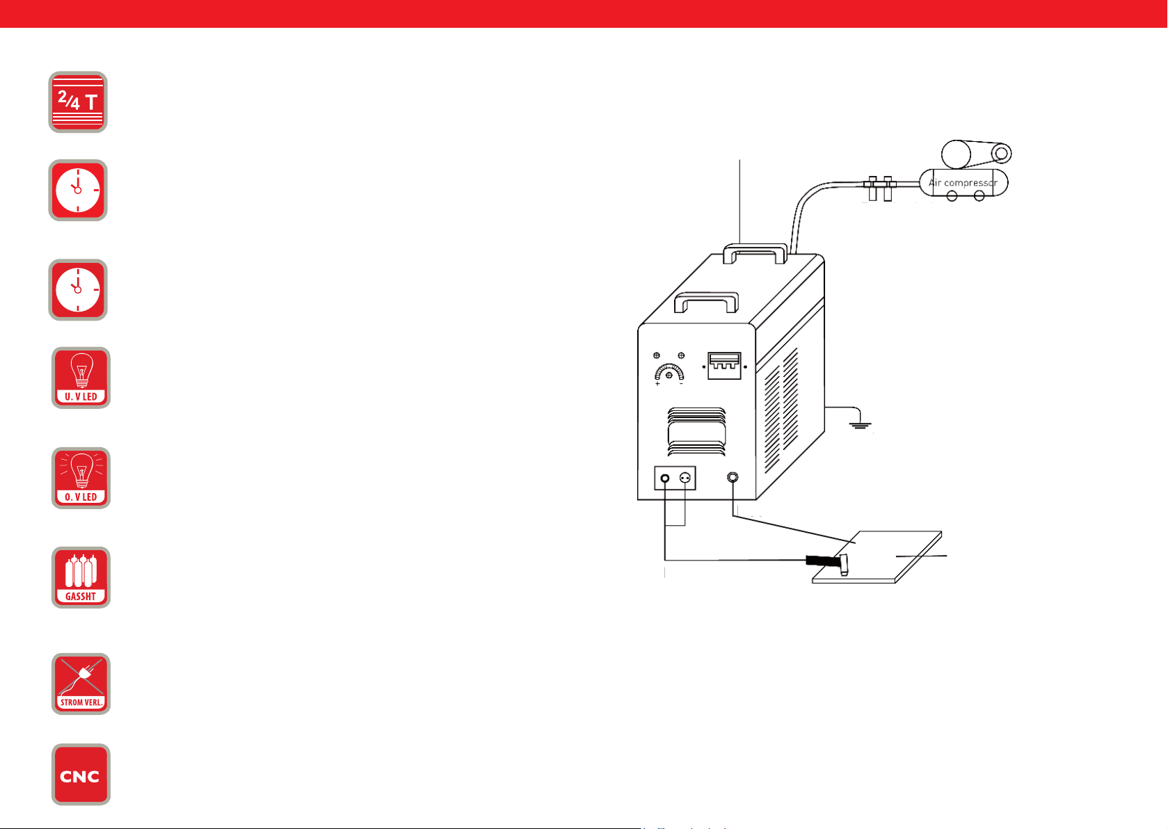
IT
IT
13.
14.
15.
16.
17.
2T/4T = Interruttore di selezione
POST FLOW = con questo tasto potete regolare il tempo di deusso
del gas.
TEST GAS = protezione.
4U.V LED = Under Voltage LED. Il display al LED si illumina se la tensione è sotto i 330 V.
O.V LED = Over Voltage LED. Il display al LED si illumina se la tensione supera i 420 V.
Schema dei collegamenti S-Plasma 55H
Cavo di
alimentazione
Compressore
Valvola di
riduzione della
Sicurezza
C avo di messa a
18.
GASSHT = Il LED si illumina se la macchina non dispone di usso di
gas o quest‘ultimo è a livelli minimi.
19.
FASI PERDITA DI CORRENTE = Se al dispositivo non sono collegate
2 fasi di corrente, o solo una o due, il LED si illuma e la macchina cessa di funzionare.
20
Collegamento CNC
118 11 9
Rev. 04.04.2022 Rev. 04.04.2022
Torcia al plasma
Pezzo in
Page 61
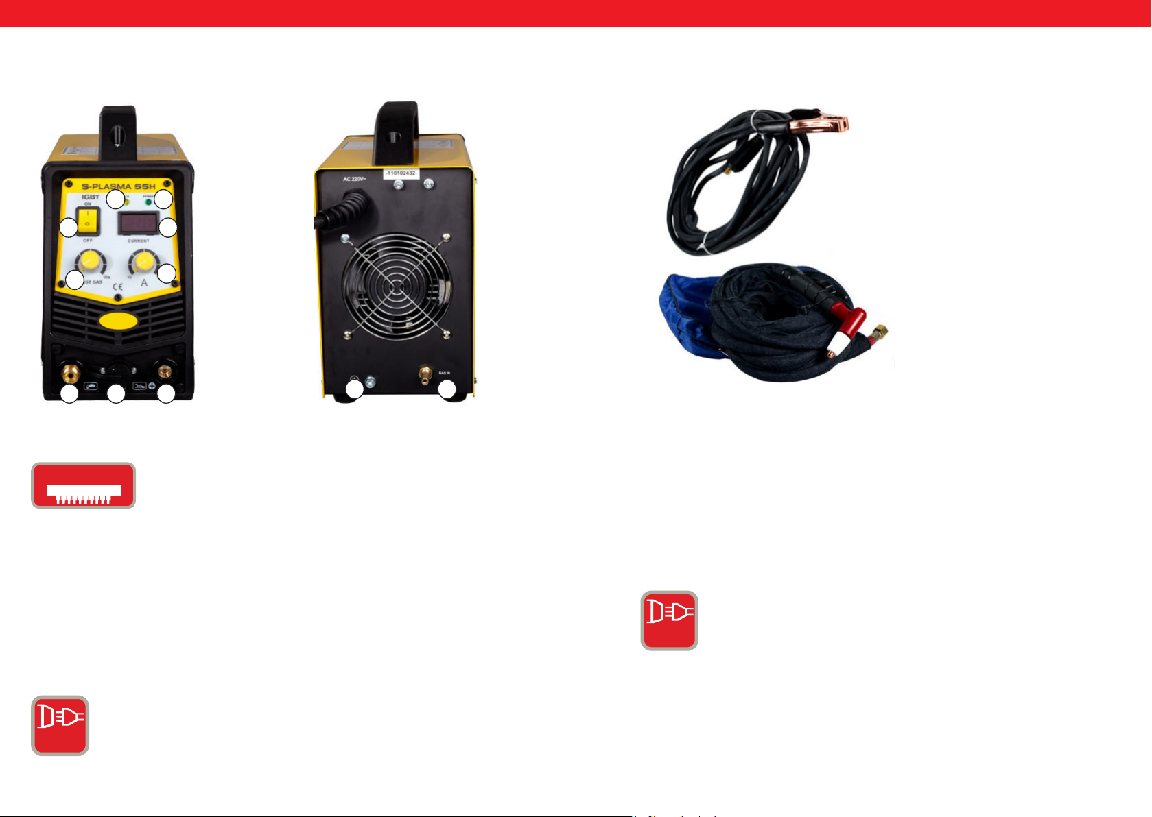
IT
IT
S-PLASMA 55 H
VISTA FRONTALE
32
0
11
Accessori
VISTA POSTERIORE
1
1. Morsetto per la messa a
4
1
567
9 8
2
IGbT
IGbT = Un transistor bipolare a gate isolato (in inglese
Insulated Gate Bipolar Transistor, abbreviato IGBbT) è un è
un dispositivo semiconduttore che sempre pià impiegato nel
settore dell‘elettronica di potenza poiché coniuga i vantaggi
dei transistor bipolari (ad es. un buon rapporto di usso, alta
corrente inversa, solidità durante le operazioni di saldatura)
con quelli dei transistor a effetto di campo (comandi che non
ALLACCIAMENTO ALLA RETE PER S-PLASMA 85H / S-PLASMA
85CNC
richiedono quasi alcun apporto di potenza in più). Gli IGBTs
possono essere considerati l‘evoluzione dei MOSFET di
potenza.
CORRENTE AD ALTA TENSIONE = Questi apparecchi
funzionano con connessione trifase (400V+/- 10%).
3 PH
ALIMENTAZIONE NORMALE: L‘apparecchio lavora con un
allacciamento monofase (230V +/- 10%).
1 PH
120 121
Rev. 04.04.2022 Rev. 04.04.2022
Page 62
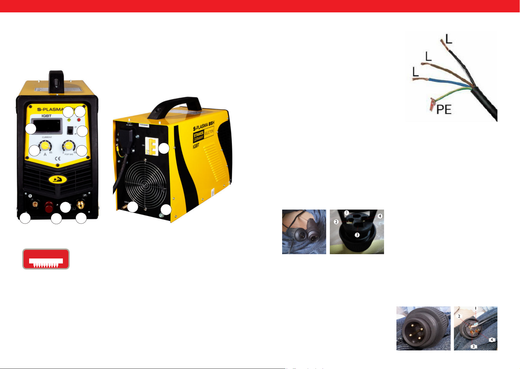
IT
PODŁĄCZENIE CNC
Aby podłączyć przecinarkę do maszyny CNC należy podłączyć dwa piny we
wtyczce: pin 3 oraz pin 4. CNC będzie działać w przypadku gdy maszyna CNC
będzie włączona, w przeciwnym przypadku będzie działało tylko cięcie ręczne.
Pin 1 oraz 2 są podłączone fabrycznie i jest to podłączenie tylko i wyłącznie do
cięcia ręcznego:
IT
S-PLASMA 85H | S-PLASMA 85CNC
VISTA FRONTALE
19
2
4
1
5
6
20
12
11
8
7
VISTA
POSTERIORE
0
9
Collegamento 85H + 125H / 85CNC + 125CNC
Piano dei collegamenti
Il contrassegno giallo-verde indica il collegamento del conduttore di protezione PE. Le tre fasi
(nero, marrone ed azzurro) possono essere ssate facoltativamente a L1, a L2 e a L3. Lasciare
che questi lavori sullo strumento siano portati
a termine soltanto da un esperto elettrotecnico
qualicato.
Attenzione!!!
Gli apparecchi di saldatura con corrente ad alta tensione possono essere installati
soltanto da un esperto elettrotecnico!
CNC COLLEGAMENTO S-PLASMA 125CNC
Per installare la tagliatrice al plasma alla macchina CNC le due spine devono essere
collegate all‘interno dell‘innesto.
Spina 4: Polo positivo
Spina 2: Polo negativo
20. Soltanto per il modello S-PLASMA 85CNC
IGbT
122 123
IGbT = Un transistor bipolare a gate isolato (in inglese
Insulated Gate Bipolar Transistor, abbreviato IGBbT) è un è
un dispositivo semiconduttore che sempre pià impiegato nel
settore dell‘elettronica di potenza poiché coniuga i vantaggi
dei transistor bipolari (ad es. un buon rapporto di usso, alta
corrente inversa, solidità durante le operazioni di saldatura)
con quelli dei transistor a effetto di campo (comandi che non
richiedono quasi alcun apporto di potenza in più). Gli IGBTs
possono essere considerati l‘evoluzione dei MOSFET di
potenza.
Rev. 04.04.2022 Rev. 04.04.2022
CNC COLLEGAMENTO S-PLASMA 125CNC
Per installare la tagliatrice al plasma alla macchina CNC le due spine devono essere
collegate all‘interno dell‘innesto. Pin 3 e Pin 4. La funzione CNC può essere utilizzato
solo se la macchina CNC è inserita. D‘altra parte, nel caso in cui la macchina CNC
non sia accesa, può essere effettuato solo il taglio manuale.
Pin 3: Polo positivo
Pin 4: Polo negativo
Page 63
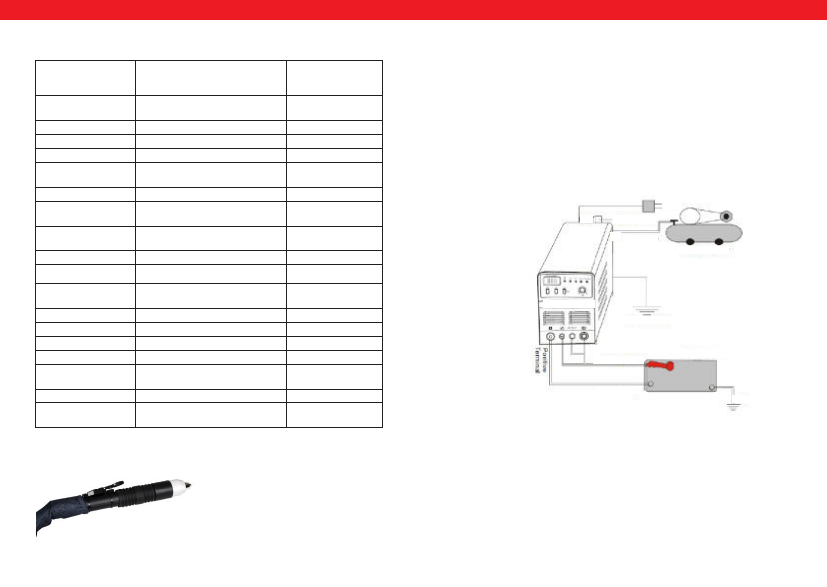
IT
IT
Dettagli tecnici
S-Plasma
55H
Tensione in entrata 230V
1-Phase
Frequenza 50Hz 50Hz 50Hz
Corrente in entrata 16A 19 A 20 A
Tensione a circuito 230 V 280 V 300 V
Grado di protezione
dell'alloggiamento
Classe di isolamento F F F
Protezione di sovraten-
sione
Raffreddamento Ventole di raff-
Elettrovalvola Sì Sì Sì
Durata max. ED con
A con ciclo di lavoro pari
al 100%
Corrente di taglio 10-55 A 20-85 A 10-125 A
Accensione Contatto Senza contatto Senza contatto
Profondità di taglio 17 mm 27 mm 34 mm
Ampiezza taglio 1 mm 1,2 mm 1,4 mm
Allacciamento compres-
sore
Peso netto 9.4 kg 19,5 kg 30 kg
Dimensione (LxAxP)
(mm)
IP20S IP20S IP21S
Sì Sì Sì
reddamento
60% 60% 60%
42,6 65,8 96,8
4,5 bar,30-100
1/min.
530/380/380 660/370/450 660/370/450
S-Plasma 85H
und
S-Plasma 85CNC*
400V
3-Phasen
Ventole di raffreddamento
5,5 bar,
175 l/min.
S-Plasma 125H
und
S-Plasma 125CNC*
400V
3-Phasen
Ventole di raffreddamento
7 bar
250 l/min
Installazione
1. Ogni tagliatrice al plasma è dotata di un cavo elettrico e, a seconda della
tensione in ingresso della tagliatrice al plasma, deve essere collegata alla fonte di
corrente adatto.
2. Il cavo di corrente deve essere ben collegato all‘interruttore o al connettore
per impedirne l‘ossidazione. Se possibile, esaminare con uno strumento di misurazione che il valore della tensione si trovi nella gamma necessaria.
Collegamento della trasmissione (abbozzo dell‘installazione)
400V
OUT
Regolazione
dell‘aria
compressa
Compressore
S-Plasma 125H
Messa a terra
Torcia per il
Pezzo in
Morsetto per
Messa
Attenzione: I modelli S-pPasma 85CNC e S-plasma 125CNC sono dotati di un collegamento CNC supplementare. In più questi due modelli di tagliatrice al plasma sono
forniti di una torcia semplice.:
124 125
Rev. 04.04.2022 Rev. 04.04.2022
Page 64
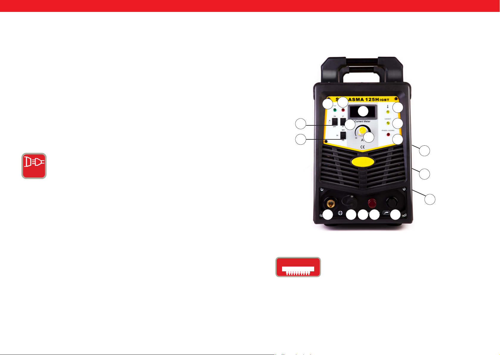
IT
IT
Funzionamento
Accendere l‘interruttore sul pannello posteriore, la luce di controllo si accende e
viene indicato il usso di corrente.
Impostare la pressione del gas corrispondente ai requisiti e aprire la valvola di
compressione.
Premere il tasto di controllo sulla torcia da taglio, lasciar quindi che la ventola si
azioni. In questo momento sarà possibile sentire e vedere l‘arco elettrico.
Impostare il usso di taglio in base allo spessore del pezzo in lavorazione.
Portare sul pezzo in lavorazione l‘ugello in rame della torcia (ugello in rame a una
distanza di circa 2 mm dal pezzo in lavorazione). Premere il tasto sulla torcia no
a dare avvio all‘arco, quindi alzare l‘ugello leggermente, circa 1 mm dal pezzo in
lavorazione, e cominciare a tagliare.
3 PH
CORRENTE AD ALTA TENSIONE = Questi apparecchi
funzionano con connessione trifase (400V+/- 10%).
S-PLASMA 125H | S-PLASMA 125CNC
17
16
4
15
14
13
1
2
18
19
0
9
8
7
20. Soltanto per il modello S-PLASMA 125CNC
IGbT
126 127
Rev. 04.04.2022 Rev. 04.04.2022
Un transistor bipolare a gate isolato (in inglese Insulated Gate
Bipolar Transistor, abbreviato IGBbT) è un è un dispositivo
semiconduttore che sempre pià impiegato nel settore
dell‘elettronica di potenza poiché coniuga i vantaggi dei
transistor bipolari (ad es. un buon rapporto di usso, alta
corrente inversa, solidità durante le operazioni di saldatura)
con quelli dei transistor a effetto di campo (comandi che non
richiedono quasi alcun apporto di potenza in più). Gli IGBTs
possono essere considerati l‘evoluzione dei MOSFET di
potenza.
10 6 5
20
Page 65
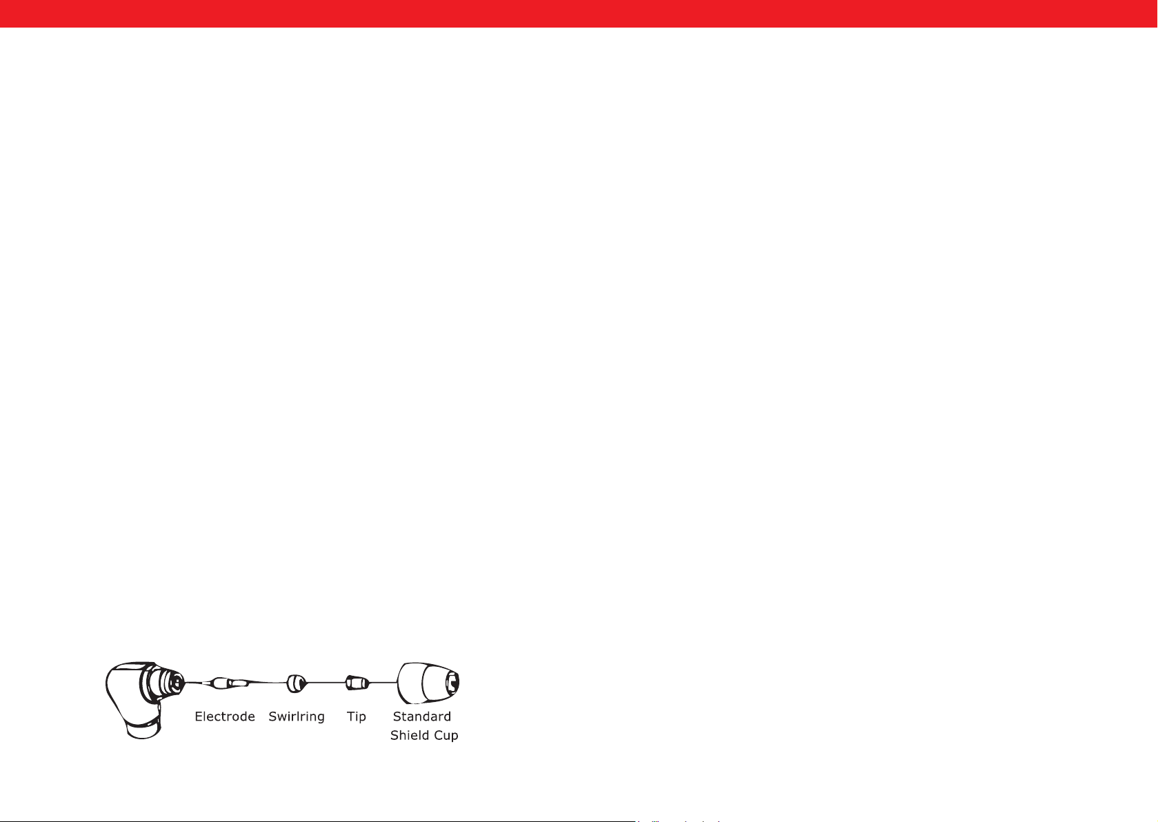
IT
IT
INSTALLAZIONE
A. Disimballaggio
Rimuovere tutti gli elementi contenuti nella confezione e controllare di aver ricevuto
tutti gli articoli elencati nella bolla di spedizione.
B. Postazione di lavoro
Assicurarsi che l‘ambiente di lavoro sia sufcientemente areato. L‘apparecchio viene
raffreddato tramite una ventola assiale che, posta sulla parte posteriore della saldatrice,
consente una ventilazione costante dell‘apparecchio.
(Avvertenza! Il rivestimento deve essere installato im modo tale che i fori di ventilazione si trovino più vicini alla parte anteriore dell‘apparecchiatura. Lasciare almeno circa
15 cm sulla parte anteriore e 15 cm su entrambi i lati per favorire una facile pulizia.
Se l‘apparecchiatura dovesse essere utilizzata con raffreddamento non sufciente, si
riduce fortemente la durata ciclica.
C. Collegamento con l‘entrata del cavo
Ogni apparecchio è dotato di un cavo di alimentazione principale che è responsabile
della creazione dell‘amperaggio e della tensione dell‘apparecchio stesso. Se esso è collegato a una corrente che superi la tensione necessaria o se la fase non è correttamen-
te allacciata, il dispositivo può risultarne seriamente danneggiato. Nel caso non vengano
rispettate le norme di sicurezza sopra citate e l‘apparecchio dovesse di conseguenza
danneggiarsi, la validità della garanzia decade.
D. Collegamento della torcia
Collegare la torcia con l‘invertitore in modo che il tubo dell‘aria, ssato all‘estremità
della torcia, giri sul pezzo di collegamento della torcia, che è ssato alla parte anteriore
della macchina. Assicurarsi che il montaggio sia corretto serrando leggermente con una
chiave meccanica. Non stringere troppo.
A. Processo per l‘assemblaggio della pistola
Installare la pistola con i rivestimenti della protezione protettiva rivolti all‘insù e girare
la copertura protettiva dalla pistola. (La protezione tiene insieme la punta, l‘anello di
ceramica e l‘elettrodo). Rimuovere la punta, l‘anello di ceramica di girata e l‘elettrodo.
Rimettere insieme l‘elettrodo, l‘anello di ceramica e la punta. Sostituire le parti consumate, se necessario. Portare la protezione sulla testa della pistola e tirarla con le mani
no a che loro non sia stabile e tesa. Se durante questa procedura si dovesse notare
una certa resistenza, esaminare i letti e la disposizione delle singole componenti prima
di cominciare con il lavoro.
Avvertenze
Per alcune pistole, che non hanno elettrodi permutabili, è necessario anche accertarsi
che l‘elettrodo sia ssato bene tramite l‘uso di pinze, al ne di garantire un collegamento elettrico sicuro.
UTILIZZO
A. L‘inizio
Accendere l‘interruttore della corrente in posizione „ON“. Posizionarsi in modo
tale da poter leggere la pressione dell‘aria dell‘apparecchio senza problemi. Premere
l‘interruttore della pistola (l‘aria fuoriuscirà fuori dalla pistola), impostare la ventola
regolatrice dell‘aria a circa 6-7 (Bar) e rilasciare poi la pistola.
Avvertenze
La pressione d‘aria ha gamma di accettazione generale tra 5 e 8 Bar. Si possono compiere tutti i possibili tentativi desiderati, ma è richiesta sempre un‘attenzione particolare
al non fare abbassare troppo la pressione d‘aria, in quanto ciò può causare danni ai
materiali logorabili. Assicurare il morsetto di messa a terra alla postazione di lavoro.
Collegare il morsetto con la parte principale dell‘oggetto in lavorazione, non alla parte
che verrà rimossa.
B. Taglio
STRUTTURA DELLA PISTOLA
128 129
Rev. 04.04.2022 Rev. 04.04.2022
1. Taglio trascinato
Mantenere la punta della pistola sulla supercie del pezzo in lavorazione, premere
l‘interruttore della pistola e spostare la punta della pistola no a che non venga a con-
tatto col pezzo in lavorazione e che l‘arco di taglio non si sia stabilito. Dopo la generazione dell‘arco di taglio spostare la pistola nel senso voluto in maniera tale che la
punta della pistola rimanga facilmente piegabile e che sia mantenuto il contatto con il
pezzo in lavorazione. Questa modalità di lavoro è denominata taglio trascinato. Evitare
movimenti bruschi che possano causare la fuoriuscita di scintille dal lato superiore del
pezzo in lavorazione. Spostare la pistola a una velocità tale che l‘accumulazione delle
scintille si concentri nelle parte sottostante del pezzo in lavorazione e assicurarsi che il
materiale sia completamente reciso prima di continuare. Impostare la velocità di trascinamento a seconda delle proprie necessità.
Page 66

IT
2. Misure di manutenzione settimanali
Assicurarsi la ventilazione funzioni senza difetti. Sofare via o aspirare la polvere o la
sporcizia dalla macchina intera, compresi i ltri dell‘aria.
3. Taglio a distanza
In alcuni casi può essere vantaggioso tagliare con la punta della pistola, la quale deve
essere mantenuta circa 1/16 “a 1/8“ sopra l‘oggetto da lavorare per ridurre il materiale
che verrà sofato nuovamente dentro la punta e per massimizzare la compenetrazione
di tagli spessi nel materiale. Il taglio a distanza dovrebbe essere usato per compiere
tagli di compenetrazione o lavori di solco. È possibile, inoltre, utilizzare la tecnica di
taglio a distanza quando si taglia una lamiera, così da minimizzare il rischio di schizzi di
materiali che possono danneggiare la punta.
4. Perforazione
Per la perforazione, regolare le punte approssimativamente a circa 3,2 mm sopra
l‘oggetto in lavorazione. Mantenere la pistola leggermente piegata per tenere lontane
scintille sia dalla punta della pistola che dall‘utente. Azionare l‘arco principale e abbas-
sare la punta della pistola no a che l‘arco di taglio principale non esca fuori e che non
comincino a formarsi delle scintille. Iniziare con la perforazione su una supercie di
prova non riutilizzabile e, se tutto funziona senza problemi, cominciare con la perfora-
zione nella linea di taglio precedentemente denita.
NÁVOD K POUŽITÍ
S-PLASMA 55H | S-PLASMA 85H
S-PLASMA 125H | S-PLASMA 85CNC
S-PLASMA 125CNC
MANUTENZIONE
Vericare che la pistola non abbia subito danni di usura, non abbia fenditure e che non
ci siano cavi scollegati. Sostituire o riparare parti danneggiate dell‘apparecchio prima
dell‘utilizzo. Un ugello della pistola molto logoro comporta una riduzione di velocità,
una diminuzione della tensione e può causare la curvatura del taglio. Ciò che contraddistingue un ugello troppo logoro è un‘apertura prolungata o troppo grande di
quest‘ultimo. La parte esterna dell‘elettrodo non deve essere più profonda di 3,2 mm.
Sostituire immediatamente una parte dell‘elettrodo se completamente usurata o non
conforme alle norme descritte. Se il cappuccio protettivo non si ssa facilmente, si
prega di controllare la condizione della lettatura.
Attenzione: Assicurarsi sempre che l‘apparecchio sia completamente
spento prima di effettuare la sostituzione dell‘ugello o dell‘elettrodo.
Verica
1. L‘alloggiamento deve sempre essere assolutamente collegato alla messa a terra.
2. Fare attenzione che tutti i collegamenti siano collegati saldamente.
3. Fare attenzione al corretto tensionamento del cavo d‘alimentazione.
4. Assicurarsi che i cavi e i tubi essibili non siano danneggiati o logori.
expondo.de
130 131
Rev. 04.04.2022 Rev. 04.04.2022
131
Page 67

CZ
CZ
Tento manuál obsahuje popisy, návod k použi a základní postupy pro Stamos Germany
plazmovou řezačku S-Plasma 55h / 85h / I25H. Prostudujte si tento manuál detailně.
Kompletní porozumění vlastnos a možnos využi zařízení je předpokladem pro jeho
správné použi.
• Chraňte sebe a ostatní před zraněním. Pečlivě si přečtěte a dodržujte bezpečnostní
opatření.
• Opravy, používání a údržbu produktu by měly provádět pouze kvalikované osoby.
• Během používání přístroje zdržujte každého, především dě, od místa jeho použi
Horký kov a jiskry jsou odfukovány od plazmového oblouku. Tyto jiskry, žhavý kov,
horký pracovní nástroj a horké čás pracovního nástroje mohou způsobit požár nebo
popáleniny. Zkontrolujte pracovní prostředí a před použim zařízení se přesvědčte, že
je vhodné na tuto práci.
• Odstraňte všechny hořlaviny v dosahu 10,7 m od svářecího přístroje.
• Pokud to není možné, pečlivě a vhodným materiálem tyto předměty přikryjte.
• Neřezejte tam, kde se mohou létající jiskry setkat s hořlavým materiálem.
• Chraňte sebe a ostatní před jiskrami a roztaveným kovem.
• Mějte na pamě, že se jiskry a horké materiály při řezání mohou snadno dostat
přes malé trhliny a otvory do přilehlých oblas.
• Dívejte se stále po ohni a vždy mějte při sobě hasicí přístroj.
• STAMOS WELDING GROUP
• Uvědomte si, že řezání na stropě, podlaze nebo jejich částech, může způsobit
požár na prolehlé straně, která není viditelná.
Připojte pracovní kabely co nejprakčtěji se zásuvkou ležící v blízkos pracoviště. Tím
zabráníte, že bude napájecí kabel rozprostřen po celé místnos na neznámém povrchu,
který by mohl způsobit elektrický šok, jiskry a vznik pořáru.
• Nepoužívejte plazmovou řezačku na rozmrazování potrubí.
• Zásadně neřezejte nádoby, které mohou obsahovat hořlavé materiály. Ty musí být
nejdříve vyprázdněny a důkladně vyčištěny.
• Neřezejte v ovzduší, které obsahuje výbušný prach nebo plyny.
• Neřežte pod tlakem stojící válce, vedení a nádoby, které jsou pod tlakem.
• Neřežte v nádobách, v nichž byly uloženy zápalné látky.
• Noste ochranné oblečení, jako např. kožené rukavice, tlusté košile, kalhoty bez
manžet, vysoké boty a ochranu hlavy.
• Neumisťujte pracovní plochu na hořlavé povrchy. Odstraňte ze sebe vše hořlavé,
jako např. butanové zapalovače, nebo sirky ještě před m, než začnete řezat.
• Dodržujte podmínky pro práci s ohněm a ujistěte se, že máte v blízkos hasicí
přístroj. Kontakt s nabitými elektrickými komponentami může způsobit závažné
otřesy nebo dokonce vážné popáleniny. Přístroj a pracovní okruh jsou elektricky
nabité, pokud je proud zapnutý. Vstupní elektrický obvod a vnitřní elektrický cyklus
přístroje jsou také pod napěm, pokud je proud zapnutý.
Řezání plazmou vyžaduje ke spuštění a udržení oblouku vyšší počet voltů než je
pravidlem u svařování (200-400 V). Zařízení ale disponuje pistolí, která je vybavená
bezpečnostním zámkem, který zařízení automacky vypne, pokud se ochranný št
rozpus, nebo se špice dotkne elektrody uvnitř hubice. Nesprávná instalace nebo
uzemnění vybavení zařízení představují velké nebezpečí.
• Nikdy se nedotýkejte elektrických součás.
• Používejte suché, neperforované izolační rukavice a ochranu těla.
• Izolujte se od předmětu a země, přičemž použijte suchou izolační pokrývku, nebo
překrývací plachtu, které jsou dostatečně velké na to, aby zabránily jakémukoliv
tělesnému kontaktu s prací nebo zemí.
• Nedotýkejte se žádných čás hořáku, pokud je právě v kontaktu s předmětem, nebo
se zemí.
• Před čištěním, výměnou, nebo kontrolou čásí pistole, vypněte napájení.
• Na výkonovém měniči nemohou explodovat spolehlivé díly, pokud jsou zásobeny
proudem. Při zacházením s měničem vždy používejte obličejový št a noste svršní
oděv s dlouhým rukávem.
• EXPLODUJÍCÍ DÍLY MOHOU ZPŮSOBIT ZRANĚNÍ.
• Jiskry a kovy stříkají z místa svařování.
• ODLETUJÍCÍ JISKRY MOHOU ZŮSOBIT ZRANĚNÍ.
• Noste obličejový št nebo ochranné brýle s bočním krytem.
• Používejte vhodnou ochranu těla, abyste chránili pokožku.
• Noste žáruvzdorné špunty do uší nebo jinou ochranu sluchu, abyste zabránili tomu
že se jiskry dostanou do uší.
• Obloukové paprsky ze řezání produkují obrovské množství viditelných a neviditelných
(ultraalových a infračervených) paprsků, které mohou popálit oči a kůži.
• OBLOUKOVÉ PAPRSKY MOHOU POPÁLIT OČI A KŮŽI
• Noste ochranu obličeje (přilbu nebo št) s vhodným odsnem, který slouží jako ltr
na obličej a oči při svařování a m Vás chrání.
• Bezpečnostní normy doporučují odsn č. 9 (č. 8 jako minimum) pro všechny řezací
procesy o síle menší než 300 A. Mohou být použity málo ltrované barevné odsny,
když je oblouk schován za pracovním předmětem.
• Noste otestované ochranné brýle s bočním panelem pod přilbou nebo štem.
• Používejte ochranné zástěny, abyste tak ostatní ochránili před oslepujícím zářením
132 133
Rev. 04.04.2022 Rev. 04.04.2022
Page 68

CZ CZ
a jiskrami. Varujte ostatní, aby se nedívali do světelného oblouku.
• Noste ochranný oděv z odolného, nehořlavého materiálu (kůže, těžké bavlny nebo
vlny) a vhodné pracovní boty.
• Před instalací zařízení vypněte vstupní proud, nebo se sami izolujte od objektu
a země za použi suchých izolačních podložek.
• Zkontrolujte a ujistěte se, že je zemnící drát napájecího kabelu správně připojen
k zemnícímu kontaktu nebo kabelová zástrčka připojena s řádně uzemněnou
zásuvkou.
• Vždy zkontrolujte připojení uzemnění.
• Před m, než provedete vstupní připojení, připojte vhodný zemnicí vodič.
• Pravidelně kontrolujte napájecí kabel ohledně jeho poškození či izolování. V případě
škod kabel vyměňte: odizolovaný kabel může způsobit smrtelná zranění.
• Vypněte zařízení, pokud se právě nepoužívá.
• Zkontrolujte kabely a okamžitě je nahraďte, pokud vykazují nadměrné stopy
opotřebení, nebo jsou poškozené.
• Nenavíjejte kabel zařízení kolem Vašeho těla.
• Uzemněte pracovní předmět na dobrém, elektricky uzemněném povrchu. Použijte
prosím jen dobře zachované vybavení.
• Okamžitě opravte nebo vyměňte poškozené čás zařízení. Při práci ve výškách se
připoutejte bezpečnostním pásem.
• Udržujte všechny díly a kryty na jednom místě.
• Držte se daleko od špičky pistole a vodicího oblouku, když je tlačítko ssknuté.
• Připojte pracovní kabel k dobrému kovového kontaktu pracovního předmětu (žádný
kus, který by mohl spadnout), nebo pracovního stolu tak blízko řezačky, jak se zdá
být nejvhodnější.
• Izolujte pracovní svorku, pokud není připojena s pracovním předmětem, abyste se
tak vyhnuli kontaktu s jakýmkoliv kovem.
Vypněte zařízení, odpojte napájecí kabel, zkontrolujte napě na vstupním kondenzátoru
a než se dotknete čás přístroje, ujistěte se, že se napě blíží nule. Předm, než se
dotknete jakékoliv čás zařízení, zkontrolujte kondenzátory ohledně údajů, které jsou
popsány v kapitole údržba v manuálu.
Na výkonovém měniči nemohou explodovat spolehlivé díly, pokud jsou zásobeny
proudem. Při zacházením s měničem vždy používejte obličejový št a noste svršní oděv
s dlouhým rukávem.
Jiskry a kovy stříkají z místa svařování.
• Noste obličejový št nebo ochranné brýle s bočním krytem.
• Používejte vhodnou ochranu těla, abyste chránili pokožku.
• Noste žáruvzdorné špunty do uší nebo jinou ochranu sluchu, abyste zabránili tomu
že se jiskry dostanou do uší.
• Obloukové paprsky ze řezání produkují obrovské množství viditelných a neviditelných
(ultraalových a infračervených) paprsků, které mohou popálit oči a kůži.
• Noste ochranu obličeje (přilbu nebo št) s vhodným odsnem, který slouží jako ltr
na obličej a oči při svařování a m Vás chrání.
• Bezpečnostní normy doporučují odsn č. 9 (č. 8 jako minimum) pro všechny řezací
procesy o síle menší než 300 A. Mohou být použity málo ltrované barevné odsny,
když je oblouk schován za pracovním předmětem.
• Noste otestované ochranné brýle s bočním panelem pod přilbou nebo štem.
• Používejte ochranné zástěny, abyste tak ostatní ochránili před oslepujícím zářením
a jiskrami. Varujte ostatní, aby se nedívali do světelného oblouku.
• Noste ochranný oděv z odolného, nehořlavého materiálu (kůže, těžké bavlny nebo
vlny) a vhodné pracovní boty.
• Před instalací zařízení vypněte vstupní proud, nebo se sami izolujte od objektu
a země za použi suchých izolačních podložek.
• Zkontrolujte a ujistěte se, že je zemnící drát napájecího kabelu správně připojen k
Obecné vysvětlení plazmy: Plazmové řezačky fungují tak, že trubičkou stříkají plyn
(např. vzduch) pod tlakem. Uprostřed těchto kanálů se nachází negavně nabitá
elektroda, přičemž se tryska nachází přímo pod ní. Točící se kroužek dovede plazmu k
tak rychlému točení, kolik ji jen dovolí.
Pokud tryska přijde do styku s kovem, vytvoří se koloběh. Silná jiskra je pak produkována
mezi elektrodou a kovem. Zamco vstupní plyn proudí skrz trubici, jiskra ohřívá
plyn, dokud nedosáhne čtvrtého stavu. Tato reakce způsobuje proud řízené plazmy,
cca 16,649 ° C horké, že se dále pohybuje 6.096 m / s a nechá redukovat kov v páru
a roztavené výměšky. Plazma jako taková vede elektrickou sílu proudu. Pracovní cyklus,
díky kterému vzniká oblouk, trvá tak dlouho, jak je proud veden k elektrodě a plazma
zůstává v kontaktu s kovem, který se zpracovává. Řezací hubice má druhou skupinu
kanálů. Tyto kanály propouštějí konstantní proud ochranného plynu a tlak tohoto
proudu kontroluje poloměr plazmového záření.
Tento stroj je koncipován pouze k využí stlačeného vzduchu jako „plynu“.
134 135
Rev. 04.04.2022 Rev. 04.04.2022
Page 69
CZ CZ
Automacký oběh potlačování proudu chrání před přepěm až do hodnoty popsané
v technickém datovém listu.
Obvod tepelné ochrany je uveden do provozu, když zařízení překročí dobu zapnu. To
způsobí zastavení zařízení.
Doba zapnu je procentní sazba provozní doby (měřená v minutách) jedné 10 minutové
periody, během které může být stroj při běžných teplotách nepřetržitě používán. Pokud
vypočtenou dobu použi překročíte, spus se ochrana pro přehřá, která se přístroj
vypne, dokud se nezchladí na normální teplotu. Nepřetržité překročení vypočtené
doby použi může stroj enormě poškodit.
0.
On
On / o vypínač
Off
1.
Ovládání napájení:
CURRENT = nastavitelný hlavní proud.
3.
Indikátor napájení = když je stroj zapnutý, kontrolka se rozsví.
4.
LED displej:
Ukazuje aktuální sílu ampérů.
5.+6.
Připojení pro plazmový hořák:
Vysoká řezná rychlost plazmového oblouku dovolí vysokou rychlost
řezu při současně vysoké kvalitě. Nevyžaduje žádný speciální plyn.
Použi normálního tlaku vzduchu a snadné ovládání jsou garancí
bezproblémového použi při výrobě karoserií, kontejnerů a v ocelárnách,
stejně jako v oblas výroby klimazace, topení atd.
7.
Připojení na zemnicí kabel
2.
Přežení / chyba LED:
Při následujících dvou situacích se kontrolka rozsví:
a) Má-li zařízení chybnou funkci a nemůže být spuštěno
b) Pokud řezačka překročí standardní zažení, zapne se ochranný modus
a stroj zastaví svoji funkci. To znamená, že zařízení přetane pracovat, aby
mohla být znovu dosažena vhodná pracovní teplota poté, co zařízení bylo
přehřáté. Z tohoto důvodu přejde zařízení do klidového stavu. Během
tohoto procesu sví červená kontrolka na předním panelu. V tomto
případě nemusíte zástrčku vytahovat ze zásuvky. Během chlazení může
venlace zařízení pracovat nadále, aby urychlila chlazení. Pokud červené
světlo dále nesví, klesla teplota na normální provozní teplotu a zařízení
může být znovu uvedeno do provozu.
136 137
Rev. 04.04.2022 Rev. 04.04.2022
8.
GAS
AIR
Plynová / vzduchová přípojka
Page 70
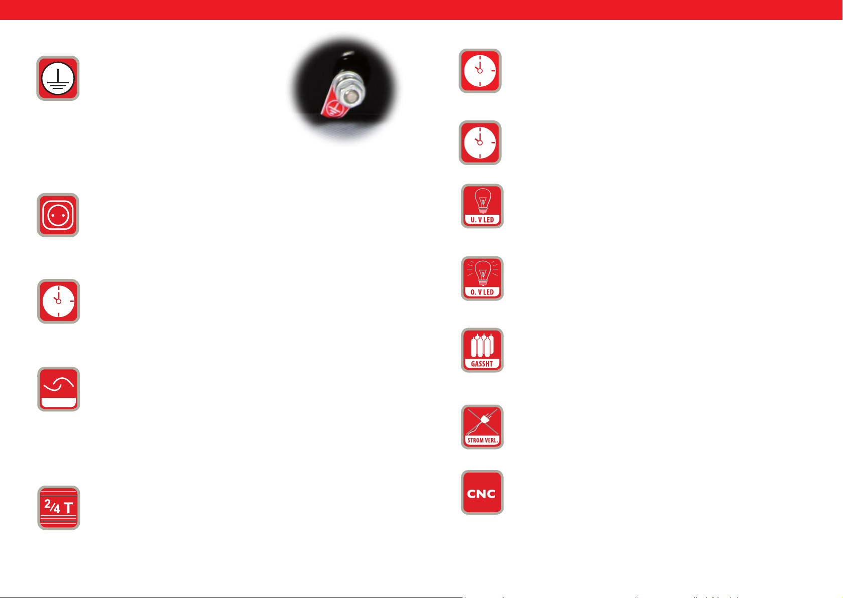
CZ CZ
9.
10.
11.
UZEMNĚNÍ:
Za každým svářecím strojem
je šroub a značka k potřebnému uzemnění.
Před použim je nezbytné spojit
obal řezacího stroje se zemí pomocí kabelu,
jehož
řez nesmí být menší než 6mm,
abyste se vyhnuli potenciálním problémům
při únikem elektrickýho proudu.
Dodatečné napájení pro hadici plazmového hořáku.
POST TIME = Dofuk plynu regulovatelný v sekundových intervalech. Tato
regulace je důležitá k tomu, aby se roztavený materiál ochladil a byl tak
chráněn před oxidací.
14.
POST FLOW = s mto tlačítkem lze upravit dobu dofuku plynu.
15.
TEST GAS = ochrana.
16.
4U.V LED = Podpě. Pokud napě klesne pod 330V, tato LED se rozsví.
17.
O.V LED = přepě. Pokud stoupne napě nad 420V, tato LED se rozsví.
18.
12.
rozsví se LED.
ROCKER SWITCH = Pokud přístroj není nastavený v sebexační pozici,
GASSHT = pokud stroj nemá žádný nebo nedostatečný tok plynu,
SWITCH
držte k začátku řezání startovací tlačítko na řezacím hořáku.
K ukončení řezu pusťte tlačítko. Tento způsob řezání je vhodný na
řezání krátkých spojů.
Pokud je řezací element nastavený ve xované poloze, stlačte jednou
tlačítko na hořáku a elektrický oblouk se zapálí. Tak můžete nepřetržitě
řezat. Sskněte znovu spínač pro zastavení řezu. Tento způsob
plazmového řezání je vhodný na řezání dlouhých spojů.
19.
FÁZE ZTRÁTA PROUDU= Pokud na zařízení není připojena na 3
proudová fáze a je zapojená 1 nebo 2 fáze, rozsví se LED kontrolka
a stroj přestane pracovat.
20
13.
CNC-Připojení
2T / 4T = přepínač
138 139
Rev. 04.04.2022 Rev. 04.04.2022
Page 71
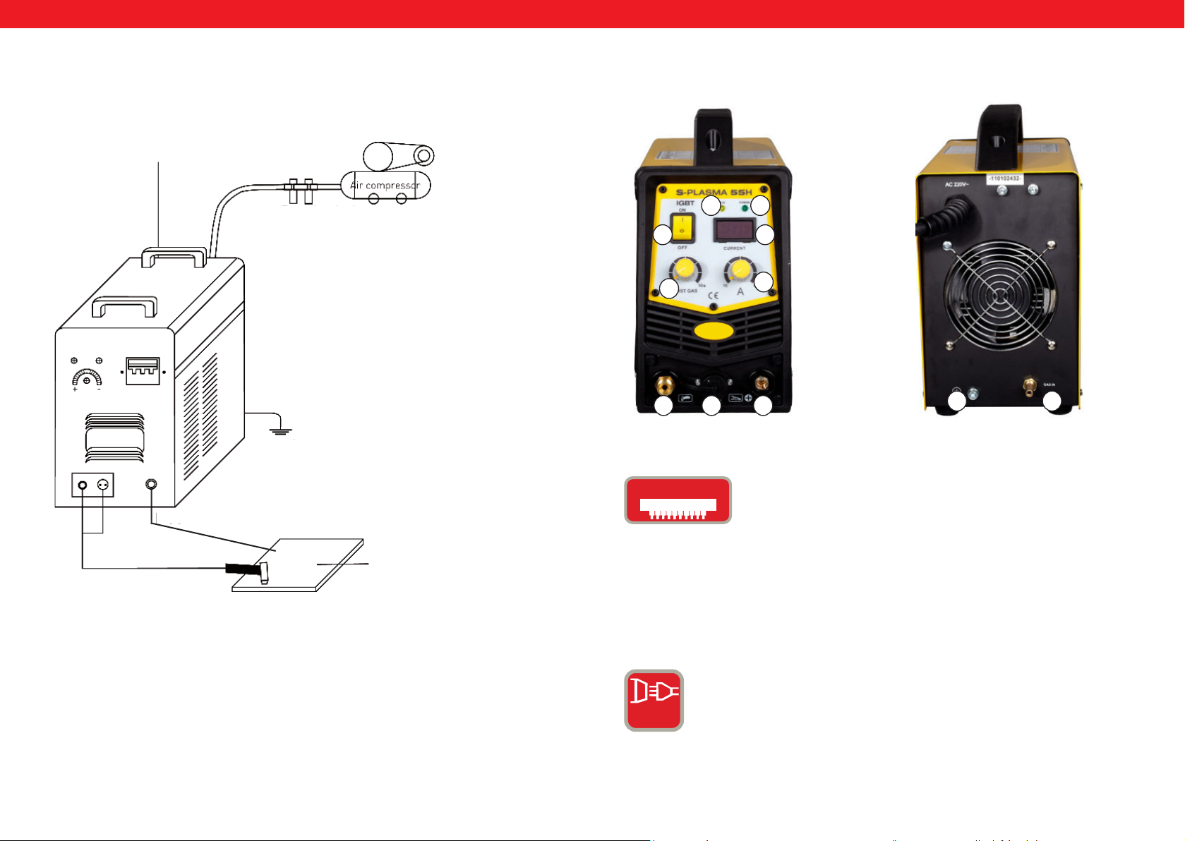
CZ CZ
Napájecí kabel
Reduktor na
kompresor
Ochrana produktu
Vzduchový
kompresor
ČELNÍ POHLED
0
11
ZADNÍ POHLED
32
4
1
567
9 8
IGbT
Zemnící kabel
Obrobek
Plazmový hořák
Bipolární tranzistor s izolovanou gate elektrodou (anglicky
Insulated Gate Bipolar Transistor, krátce IGBT) je polovodičový
článek, který se stále více využívá ve výkonové elektronice,
protože sjednocuje přednos bipolárního tranzistoru (např.
dobré chování průchodu, vysoké prahové napě, robustnost
svařovacího zařízení) a unipolárního tranzistoru. Výhodou
je také jistá odolnost vůči zkratům, protože IGBT ohraničuje
zatěžovací proud. IGBT je dalším stupněm v rozvoji verkální
výkonné technologie MOSFET
NORMÁLNÍ PROUD: Přístroj pracuje s 1-fázovým připojením
(230V +/- 10%).
1 PH
140 141
Rev. 04.04.2022 Rev. 04.04.2022
Page 72
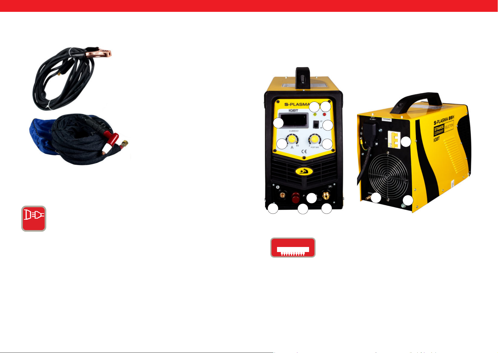
CZ CZ
1
1. Zemnící svorka
2
Silnoproud= Tato zařízení pracují s 3fázovým připojením (400
v ± 10 %)
3 PH
Bipolární tranzistor s izolovanou gate elektrodou (anglicky
Insulated Gate Bipolar Transistor, krátce IGBT) je polovodičový
článek, který se stále více využívá ve výkonové elektronice,
protože sjednocuje přednos bipolárního tranzistoru (např.
dobré chování průchodu, vysoké prahové napě, robustnost
svařovacího zařízení) a unipolárního tranzistoru. Výhodou
je také jistá odolnost vůči zkratům, protože IGBT ohraničuje
zatěžovací proud. IGBT je dalším stupněm v rozvoji verkální
výkonné technologie MOSFET.
2. Plazmový hořák
PŘEDNÍ POHLED
19
2
4
1
5
20. Pouze pro model S-PLASMA 85CNC
6
IGbT
12
11
20
7
Bipolární tranzistor s izolovanou řídící elektrodou (Insulated Gate
Bipolar Transistor-IGBT) je polovodící stavební element, který je
stále více používán ve výkonné elektronice, protože sjednocuje
přednos bipolárního transzistoru (např. dobré propuštěcí
vlastnos, vysoké blokovací napě, robustnost u svářeček) a
přednos unipolárního tranzistoru (ovládání téměř bez výkonu).
Užitečná je také jistá robustnost pro zkratům, protože IGBT
ohraničuje zátežový proud. IGBT je dalším vývojem verkálního
výkonu MOSFET.
ZADNÍ POHLED
0
8
9
142 143
Rev. 04.04.2022 Rev. 04.04.2022
Page 73
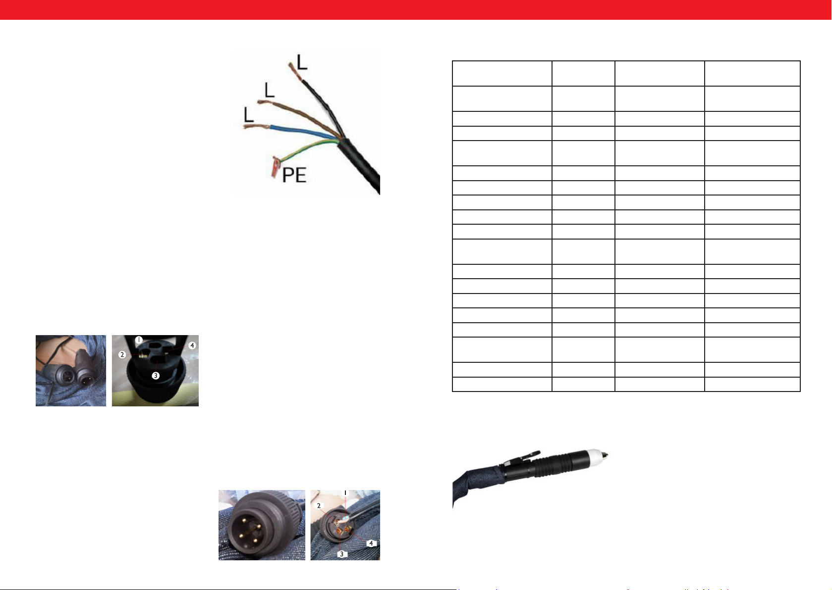
PODŁĄCZENIE CNC
Aby podłączyć przecinarkę do maszyny CNC należy podłączyć dwa piny we
wtyczce: pin 3 oraz pin 4. CNC będzie działać w przypadku gdy maszyna CNC
będzie włączona, w przeciwnym przypadku będzie działało tylko cięcie ręczne.
Pin 1 oraz 2 są podłączone fabrycznie i jest to podłączenie tylko i wyłącznie do
cięcia ręcznego:
CZ CZ
Žluto-zelený drát je určen na přípojku
ochranného vodiče PE. Tři fáze (černá,
hnědá a modrá) lze připojit k jakékoliv LI,
L2 a L3. Prosím, přenechte tuto práci pouze
odborníkům.
Řezačky se silnoproudým připojením mohou být připojeny pouze kvalikovaným
elektrikářem!
Chcete-li připojit řezačku na CNC stroj, musí být dva otvory v zásuvce propojeny se
zástrčkou.
Konektor 4: Kladný pól
konektor 2: Negavní pól
Vstupní napě 230V
I-fáze
Frekvence 50Hz 50Hz 50Hz
Vstupní proud 32.2 A I9A 20 A
Napě při běhu
naprázdno
Stupeň ochrany krym IP20S IP20S IP21S
Třída izolace F F F
Přepěťová ochrana Ano Ano Ano
Chlazení Venlátor Venlátor Venlátor
Magnecký venl Ano Ano Ano
Doba zapnu (ED) při
max. A
A při 100 % duty cycle
Řezací proud 10-55 A 20-85 A 10-125 A
Zapalování Kontakt Non - kontakt Non - kontakt
Hloubka řezu 17 mm 27 mm 34 mm
Šířka řezu 1 mm 1,2 mm 1,4 mm
Připojení kompresoru 4,5 bar,30-100
Čistá hmotnost 9.4 kg 19,5 kg 30 kg
Rozměry D / Š / V (mm) 530/380/380 660/370/450 660/370/450
230 V 280V 300V
60% 60% 60%
42,6 65,8 96,8
1/min.
400V
3 fáze
5,5 bar,
175 l/min.
400V
3 fáze
7 bar
250 l/min
POZOR: Modely S-plasma 85CNC a S-plasma I25CNC jsou vybaveny extra portem na
CNC. Tyto dva modely jsou rovněž vybaveny jednoduchým hořákem:
Chcete-li připojit řezačku na CNC stroj, musí být dva otvory v zásuvce propojeny se
zástrčkou: PIN 3 a PIN 4. Funkce CNC funguje pod podmínkou, že je CNC stroj zapnutý.
Pokud je CNC stroj vypnutý, funguje pouze ruční řezání.
PIN 3: Pozivní pól
PIN 4: Negavní pól
144 145
Rev. 04.04.2022 Rev. 04.04.2022
Page 74
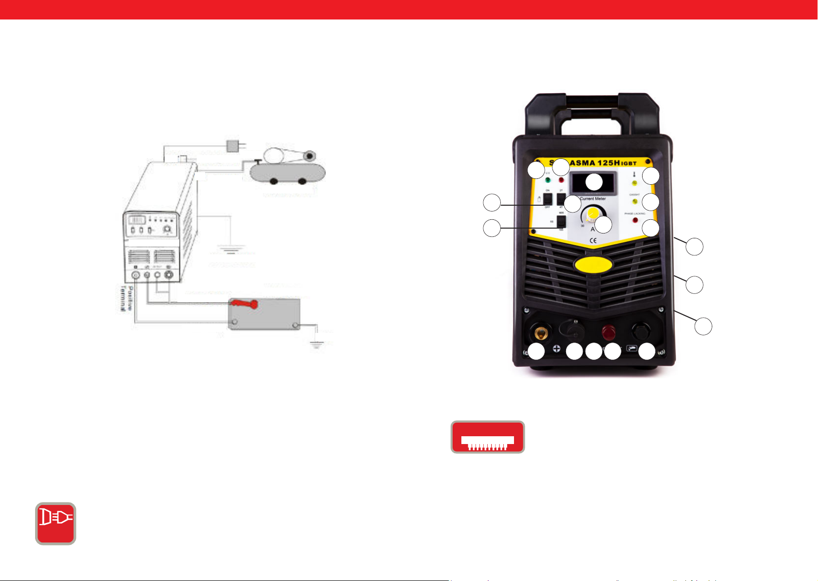
CZ
CZ
1. Každá plazmová řezačka je vybavena síťovým kabelem a podle vstupního
napě řezačky musí být připojena k odpovídajícímu napájecímu zdroji.
2. Napájecí kabel by měl dobře připojen ke konektoru, aby se zabránilo oxidaci.
Pokud je to možné, zkontrolujte pomocí měřítka, zda je napě v požadované
oblas.
400V
OUT
S-Plasma 125H
regulace tlaku
vzduchu
vzduchová
hadice
vzduchový kompresor
uzemnění tělesa
řezací hořák
obrobek
17
16
15
13
14
4
2
18
1
19
0
9
zemnící svorka
8
uzemnění
7
10 6 5
20
Zapněte hlavní vypínač na zadním panelu. kontrolka se rozsví a ukáže se aktuální
proud.
Nastavte tlak plynu dle aktuálních požadavků a otevřete kompresní venl.
Sskněte ovládací tlačítko na hořáku, pak je venl v provozu. Můžete slyšet a vidět
oblouk.
Nastavte v závislos na tloušťce obrobku řezací proud.
Připojte měděnou trysku řezacího hořáku na obrobek (měděná tryska v oblouku
je cca 2 mm od obrobku), sskněte tlačítko na hořáku, dokud se oblouk
nenastartuje, zvedněte řezací trysku asi Imm od obrobku a začněte řezat.
SILNOPROUD = Tato zařízení pracují s 3fázovým připojením (400 v ± 10 %).
20. Pouze pro model S-PLASMA 125CNC
IGbT
Bipolární tranzistor s izolovanou gate elektrodou (anglicky
Insulated Gate Bipolar Transistor, krátce IGBT) je polovodičový
článek, který se stále více využívá ve výkonové elektronice,
protože sjednocuje přednos bipolárního tranzistoru (např.
dobré chování průchodu, vysoké prahové napě, robustnost
svařovacího zařízení) a unipolárního tranzistoru. Výhodou
je také jistá odolnost vůči zkratům, protože IGBT ohraničuje
zatěžovací proud. IGBT je dalším stupněm v rozvoji verkální
výkonné technologie MOSFET.
3 PH
146 147
Rev. 04.04.2022 Rev. 04.04.2022
Page 75
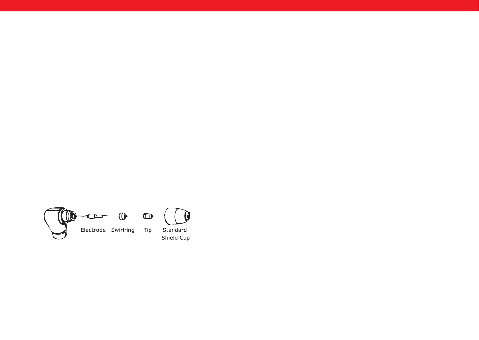
CZ
CZ
Rozbalte všechno z obalu a zkontrolujte, zda máte všechny položky, které jsou uvedené
na listu, který jste obdrželi v zásilce.
Ujistěte se, že je pracovní plocha dobře větraná. Zařízení je chlazeno axiálním větrákem,
který zajišťuje proudění vzduchu zadním panelem přes elektroniku.
Upozornění! Produkt musí být nainstalován tak, aby se větrací otvory nacházely na
přední straně přístroje ). Ponechejte alespoň 15 cm vpředu a 15 cm na obou stranách
volný prostor pro úklid. Je-li přístroj provozován bez dostatečného chlazení, je silně
snížena doba provozu.
Každé zařízení má hlavní napájecí kabel, který je odpovědný za výrobu napě a proudu.
Když je zařízení připojeno k proudu, který překračuje požadované napě, nebo je
nastavený na nesprávnou fázi, může se vážně poškodit. To nespadá do záručních
podmínek zařízení, ale vztahuje se na vinu uživatele.
Připojte hořák k invertoru, přičemž vzudchovou trubičku, která je připevněná na
konci hořáku přišroubujete na připojovací kus hořáku, který je na přední straně stroje.
Zajistěte konstrukci ještě jednou lehkým utažením klíče. Neutahujte příliš na těsno.
Nastavte pistoli s víkem ukazujícím nahoru a vytočte ho od pistole. (Ochranné víko drží
špici, keramický otočný kroužek a elektrodu pohormadě). Odstraňte špici, keramický
rotující kroužek a elektrodu. Nainstalujte elektrodu, keramický rotující kroužek
a špici opět dohromady. Vyměňte opotřebované díly, pokud je to nutné. Nainstalujte
ochranný kryt na vršek pistole, a utáhněte ho rukou, dokud nebude přiléhat. Pokud
během tohoto procesu ucíte odpor, zkontrolujte závit a uspořádání jednotlivých dílů,
než začnete pracovat.
Některé pistole nemají přepínatelné elektrody. Zde je nutné elektrodu dodatečně
utáhnout použim kleš, aby bylo zajištěno spolehlivé elektrické spojení.
Přepněte hlavní vypínač do polohy „ON“. Postavte se tak, abyste mohli ze zařízení bez
problémů odečíst hodnotu tlaku vzduchu. Sskněte tlačítko na pistoli (vzduch bude
proudit ven z pistole), nastavte regulační venl vzduchu na cca 6-7 (bar) a znovu pusťte
volič pistole.
Tlak vzduchu má obecnou oblast přije 5 až 8 bar. Můžete podle potřeby provádět
pokusy, ale je nutná opatrnost, aby tlak vzduchu neklesl příliš, protože to může vést
k poškození spotřebního materiálu. Upevněte zemnící svorku na pracovní předmět.
Připojit svorku k hlavní čás pracovního předmětu, nikoliv na čás, která se opět
odstraní.
Držte špici pistole mělce na praconím předmětu, stlačte spínač na pistoli a pohybujte se
špicí, dokud nedojde ke kontaktu s pracovním předmětem a nevytvoří se řezací oblouk.
Poté, co byl vytvořen řezací oblouk, můžete nyní pohybovat pistolí v požadovaném
směru, přičemž je špice pistole lehce ohnutá a je udržen kontakt s předmětem. Tato
pracovní metoda se nazývá řezání tažením. Vyhněte se příliš rychlým pohybům.
Jedním z ukazatelů jsou jiskry, které mohou stříkat z horní čás pracovního předmětu.
Přesouvejte pistoli jen tak rychle, že jsou jiskry koncentrovány jen na spodní straně
pracovního předmětu a před m než budete pokračovat se ujistěte, že je materiál
kompletně oddělený. Nastavte rychlost tažení, jak je požadováno.
Ověřte, zda větrání pracuje správně. Odfoukněte nebo vysajte prach a špínu před
přístrojem včetně vzduchového ltru.
148 149
Rev. 04.04.2022 Rev. 04.04.2022
Page 76

CZ
V některých případech může být výhodné držet špici pistole cca I / I6 „I / 8“ nad
pracovním předmětem. Tím se redujuje materiál, který je znovu dofukován no špice
a maximalizuje se proniknu tlustých kusů v materiálu. Distanční řezání by se mělo
používat,když je prováděno např. penetrační řezání. Můžete kromě toho také použít
vzdálenost pracovní techniky, když řežete plech. Tím snížíte riziko, že budou poškozené
špiceodstřikujícím materiálem.
K provrtání vložte špici cca 3,2 mm nad pracovním předmětem. Držte pistoli v mírném
naklonění, abyste jiskry nasměrovali od Vás. Ovládejte hlavní oblouk a snižte špici
pistole, dokud nevyjede hlavní řezací oblouk a nezačnou se tvořit jiskry. Začněte s
provrtáváním na nějakém nepoužitelném pokusném předmětu. Pokud to zde funguje
bez problémů, začněte s provrtáváním na předem určené řezací lince.
Zkontrolujte, zda pistole není poškozena, nemá trhliny, nebo nemá uvolněný kabel.
Všechny poškozené čás by měly být opraveny, nebo vyměněny. Silně opotřebované
špička/ hubice pistole vede poklesu rychlos, napě a křivé separaci. Znak silně
opotřebované špice / hubice pistole je prodloužený nebo nadměrně veliký otvor
hubice. Vnější strana elektrody nesmí být prohloubena více než 3,2 mm. Nahraďte ji,
pokud je použitější než je udávaná velikost. Pokud ochranné víko není snadné připojit,
zkontrolujte závit.
HASZNÁL ATI ÚTMUTATÓ
S-PLASMA 55H | S-PLASMA 85H
S-PLASMA 125H | S-PLASMA 85CNC
S-PLASMA 125CNC
1. Produkt by měl být vždy bezpečně uzemněn.
2. Zkontrolujte, zda jsou všechny spoje bezpečně připojené.
3. Zkontrolujte, zda je k napájecímu kabelu dodáno správné napě.
4. Ujistěte se, že kabely a hadice nejsou poškozené nebo opotřebované.
expondo.de
150 151
Rev. 04.04.2022 Rev. 04.04.2022
151
Page 77

HU
HU
Ez a felhasználói kézikönyv a Stamos Germany S-Plasma 85H/125H plazmavágó leírását,
használati utasítását és alapveto karbantartási eljárásait tartalmazza. Kérjük, alaposan
olvassa el ezt a kézikönyvet.
A készülék tulajdonságainak és felhasználásának teljes megértése biztosítja annak helyes
alkalmazását.
VIGYÁZAT
• Ügyeljen a saját és mások testi épségére. Kérjük, olvassa el gyelmesen és tartsa be
a leírt óvintézkedéseket.
• • Kizárólag szakképzett személy végezheti a készülék javítását, üzemeltetését,
karbantartását és ellenőrizését.
• • A készülék használata során harmadik személyek, különösen gyermekek, nem
léphetnek be a munkaterületre.
A VÁGÁS tűz- és robbanásveszélyes.
A forró fémet és a szikrákat a plazmaív továbbíthatja. Az elpattanó szikrák vagy forró
fémdarabok, valamint a forró munkadarab és felszerelések tüzet vagy égési sérüléseket okozhatnak. Használat előtt ellenőrizze a munkakörnyezetet és bizonyosodjon
meg róla, hogy használható benne a készülék.
• Távolítson el minden éghető anyagot 10,7 m-en belül a hegesztőberendezéstől.
• Amennyiben ez nem lehetséges, takarja le a közelben lévő tárgyakat.
• Ne vágjon olyan helyen, ahol egy kipattanó szikra éghető anyagra eshet.
• Védje magát és másokat az elpattanó szikrák és forró fémek terjedésétől.
• Mindig legyen körültekintő, ugyanis a szikrák és a forró anyagok vágáskor könnyen
átjuthatnak a kis réseken és furatokon.
• Mindig ellenőrizze, hogy nem keletkezik-e tűz. Kötelező tűzoltó készüléket tartani
a közelben.
• Mindig tartsa észben, hogy a mennyezeten, padlón vagy korlátozott területen
történő vágás közben a tűz a munkadarab ellentétes, takarásban lévő oldalán is
kigyulladhat.
Ne vágjon zárt tartályokat, például konténereket vagy edényeket
A munkakábelt a munkaterület közelében lévő hálózti aljzathoz csatlakoztassa, hogy
elkerülje a helyiségben a hálózati kábel feltobzódását, így annak kockázatát, hogy az
ismeretlen felületen áramütést, szikrát vagy tüzet okozzon.
• Ne használja a plazmavágót fagyott csövek felolvasztásához.
• Ne használja a plazmavágót gyúlékony anyagokat tartalmazó tartályok vágására. Eze-
ket előzetesen ki kell üríteni és alaposan ki kell tisztítani.
• Ne vágjon robbanásveszélyes port vagy gőzszemcséket tartalmazó környezetben.
• Ne vágjon nyomás alatt álló hengereket, vezetékeket vagy edényeket.
• Ne vágjon olyan tartályokat, melyekben korábban gyúlékony anyagokat tároltak.
• Viseljen olajmentes védőruházatot, például bőrkesztyűt, vastag inget, szegecs nélküli
nadrágot, bakancsot és sapkát.
• Ne helyezze a munkadarabot gyúlékony felületekre vagy azok fölé.
• A vágás megkezdése előtt távolítson el minden gyúlékony tárgyat, például bután
öngyújtókat vagy gyufákat.
• A tervezett munkának megfelelően végezze a vágást, tartson tűzoltó készüléket a
munkaterület közelében. Az elektromos töltettel bíró alkatrészekkel való érintkezés
súlyos áramütést vagy égési sérülést okozhat. A hegy és a munkakör azonnal feszültség alá kerül, amint az áramellátást bekapcsolják. Az áramellátás bekapcsolásakor a
tápfeszültség és a gép belső áramköre is feszültség alatt áll.
A plazmavágáshoz nagy feszültségértékre van szükség az ív létrehozásához és fenntartásához, hasonlóan a hegesztéshez (200–400 V DC), de az eszköz biztonsági zárral ellátott pisztollyal rendelkezik, amely automatikusan kikapcsolja a készüléket, ha a
védőkupak leválik vagy az elektróda hegye megérinti a fúvóka területét. A berendezés
helytelen telepítése vagy földelése nagy kockázatot jelent.
AZ ÁRAMÜTÉS ÉLETVESZÉLYES.
• Soha ne érintse meg az elektromosan töltött alkatrészeket.
• Viseljen száraz, lyukmentes szigetelt kesztyűt és védőruházatot.
• Szigetelje magát a tárgyaktól és a talajtól száraz szigetelő szőnyegekkel vagy pony-
vákkal, amelyeknek elég nagynak kell lenniük ahhoz, hogy elkerüljék a test érintkezését a talajjal és a munkadarabbal.
• Ne érintse meg a plazmapisztoly egyik részét sem, ha azok érintkeznek a munkadarabbal vagy a talajjal.
• Kapcsolja ki az áramellátást, mielőtt ellenőrzi, tisztítja vagy kicseréli a plazmapisztoly
részeit.
• A készülék telepítésekor kapcsolja ki a tápfeszültséget, vagy száraz szigetelő
szőnyegek segítségével szigetelje el magát megfelelően a tárgyaktól, illetve a talajtól.
• Ellenőrizze és bizonyosodjon meg arról, hogy a tápkábel földelővezetéke megfelelően
van-e csatlakoztatva a földelőcsaphoz, vagy a kábeldugó megfelelően csatlakozik-e az
aljzat megfelelő földeléséhez.
152 153
Rev. 04.04.2022 Rev. 04.04.2022
Page 78

HUHU
• Mindig ellenőrizze a földelő csatlakozást.
• A bemeneti csatlakozás előkészítése előtt készítse elő a megfelelő földelővezetéket.
• Rendszeresen ellenőrizze a tápkábelt sérülések és szigetelés szempontjából. Sérülés
esetén azonnal cserélje ki a kábeleket, mivel a nem szigetelt kábelek életveszélyesek
lehetnek.
• Kapcsolja ki a készüléket, ha nem használja.
• A kábelt meg kell vizsgálni és ki kell cserélni, ha a kábel túlterhelt vagy sérült.
• Ne tekerje a készülék kábelét a készülék teste köré.
• Földelje a munkadarabot jó elektromos földeléssel.
• Kizárólag jó állapotú tartozékokat használjon.
• A készülék sérült alkatrészeit azonnal meg kell javítani vagy ki kell cserélni.
• Ipari alpinisták munkavégzése során kötelező biztonsági övet viselni.
• Az összes alkatrészt és fedelet tárolja egy helyen.
• Ne tartózkodjon a plazmapisztoly hegye és az ív közelében, a gomb bekapcsolása
után.
• Rögzítse fémcsipesszel a munkakábelt a munkadarabhoz (nem szabad leválnia a darabról), vagy helyezze a munkaasztalt a vágóeszközhöz olyan közel, amennyire a megmunkáláshoz szükséges.
• Szigetelje a terminált
A tápkábel kihúzása után a készülék továbbra is jelentős EGYENFESZÜLTSÉG alatt állhat
Kapcsolja ki a készüléket, húzza ki a tápkábelt, ellenőrizze a bemeneti kondenzátor
feszültségét, és győződjön meg arról, hogy a feszültség a nulla körül van, amikor kapcsolatba lép az eszközzel. Mielőtt hozzáérne a berendezés bármely részéhez, ellenőrizze a
kondenzátorokra vonatkozó információkat a Karbantartási és üzemeltetési kézikönyvben.
AZ ELEKTROMOS ÁRAMÜTÉS ÉLETVESZÉLYES
Az inverter körül bizonyos működési szempontból nem biztonságos alkatrészek feszültség alá helyezve felrobbanhatnak. Az inverter kezelésekor mindig védje az arcát és
viseljen hosszú ujjú inget.
A FELROBBANÓ ALKATRÉSZEK sérüléseket okozhatnak.
A hegesztési felületről szikrák és fém részek pattanhatnak el.
Az ELPATTANÓ SZIKRÁK sérüléseket okozhatnak.
• Viseljen megfelelő arcvédőt vagy oldalvédővel ellátott védőszemüveget.
• Viseljen megfelelő a testet védő eszközt a bőr védelme érdekében.
• Viseljen tűzálló füldugót és egyéb hallásvédőt, hogy megakadályozza a szikrák be-
jutását a fülébe.
• A vágás során az ív látható és nem látható (ultraibolya és infravörös) sugarakat hoz
létre, amelyek szemkárosodást okozhatnak és égési sérülést okozhatnak a bőrön.
Az ÍVSUGÁR szemkárosodást és égési sérülést okozhat.
• Viseljen megfelelő színű arcvédőt (sisakot vagy maszkot), mint szűrőt, amely védi az
arcát és a szemét vágás közben.
• A biztonsági előírások a 9-es (minimum 8-as) színt írják elő minden 300 A-nál kisebb
áram esetén. Alacsonyabb szűrésű színek használhatók, ha az ív teljesen áthatol a
munkadarabon.
• Viseljen védőszemüveget oldalvédővel a sisak vagy maszk alatt.
• Használjon védőburkolatokat vagy korlátokat, hogy másokat védjen a vakító fénytől
vagy a szikráktól; gyelmeztessen másokat, hogy ne nézzenek a fényívbe.
• Viseljen tűzálló, tartós anyagból (bőr, pamut vagy gyapjú) készült védőruházatot és
megfelelő munkacipőt.
PLAZMA
Általános információk a plazmáról. A plazmavágó nyomás alatt álló gáz, például levegő
felhasználásával működik. A csatorna közepén egy negatív töltésű elektróda található,
közvetlenül alatta van a fúvóka. A forgó gyűrű hatására a plazmasugár a megengedett
sebességgel forog. Ha a negatív elektróda feszültség alá kerül, és a fúvóka hegye érintkezik a fémmel, akkor ez a kapcsolat áramkört hoz létre. Ekkor gyújtószikra keletkezik
az elektróda és a fém között.
Amikor a bejövő gáz átfolyik a csövön, a gyújtószikra addig melegíti a gázt, amíg el nem
éri a negyedik állapotot. Ez a reakció azt eredményezi, hogy az irányított plazma körülbelül 16 649 °C vagy annál magasabb hőmérsékleten 6096 m/mp sebességgel mozog,
és a fém füstté és olvadt maradékká redukálódik. A plazma maga vezeti az áramot. Az
ív keletkezését lehetővé tevő munkaáramkör addig létezik, amíg az elektróda feszültség
alatt áll, és a plazma érintkezik a megmunkálandó anyaggal. A vágó fúvókának van egy
második csatornacsoportja. Ezek a csatornák lehetővé teszik a védőgáz folyamatos
elvezetését. Ennek a gázáramnak a nyomása teszi lehetővé a plazma sugarának szabályozását.
Figyelem! A géphez gázként kizárólag sűrített levegőt lehet alkalmazni.
Áramszabályozás
Az automatikus áramkorlátozó funkció véd a túlfeszültség ellen, biztosítva a műszaki
adatlapban megadott érték fenntartását. Hővédelem A hővédő áramkör akkor aktiválódik, ha a készülék túllépi az bekapcsolási időt (duty cycle). Ez a gép leállását okozza.
Duty Cycle
A bekapcsolási idő a működési idő százaléka (percben mérve) 10 perces periódusban, amely alatt a gépet normál hőmérsékleti körülmények között folyamatosan
működtetik. Ha a bekapcsolási periódus paramétereit túllépik, a túlmelegedés elleni
védelmi rendszer aktiválódik, amely leállítja az egység működését, amíg lehűl a normál
üzemi hőmérsékletre. A meghatározott bekapcsolási idő paramétereinek folyamatos
túllépése a készülék túlzott károsodásához vezethet.
154 155
Rev. 04.04.2022 Rev. 04.04.2022
Page 79
HUHU
JELMAGYARÁZAT:
0.
On
Be/kikapcsoló gomb
Off
1.
Áramszabályozó
CURRENT = A főáram szabályozása
2.
Túlterhelés / meghibásodás = A lámpa két esetben gyullad ki:
a) ha a gép meghibásodott és nem használható.
b) ha a hegesztő túllépte a szokásos túlterhelési időt, biztonsági
módba lép, majd kikapcsol. Ez azt jelenti, hogy a készülék készenléti
üzemmódba kapcsol, miközben szabályozza a hőmérsékletet és a
túlmelegedést. A folyamat során az előlapon található gyelmeztető
lámpa kigyullad. Ebben az esetben nem szükséges kihúzni a hálózati
csatlakozót az aljzatból. A ventilátor tovább jár, hogy lehűtse a
készüléket. Ha a piros lámpa már nem világít, az azt jelenti, hogy a
készülék üzemi hőmérsékletre hűlt és újra használható.
3.
ÁRAMELLÁTÁS = a jelzőfény akkor világít, amikor a gép be van
kapcsolva.
4.
LED kijelző = az aktuális áramerősség értékét jeleníti meg.
5.+6.
Plazma elektróda (pisztoly) csatlakozás:
A plazma fényív nagy energiasűrűsége lehetővé teszi a nagy vágási
sebesség elérését, miközben biztosítja annak kiváló minőségét.
Nincs szükség speciális, drága gázra; a normál sűrített levegő használata
és a problémamentes működés garantálja a kényelmes működést a
tartályok, karosszéria és acél feldolgozásakor a fűtési, légkondicionáló
és szellőztető iparban vezetékek és szaniter rendszerek telepítésekor.
7.
Földelő vezeték csatlakozó
8.
GAS
GÁZ/ levegőcsatlakozás
AIR
156 157
Rev. 04.04.2022 Rev. 04.04.2022
Page 80
HUHU
9.
10.
11.
12.
Földelés:
Minden hegesztőeszköz hátulján található egy
csavar, és tájékoztatás a megfelelő földelés
biztosításának szükségességéről. A használat
megkezdése előtt feltétlenül szükséges, hogy a
hegesztőgépet legalább 6 mm2 keresztmetszetű
kábellel földeljék, hogy elkerüljék az elektromos
töltések kisüléséből adódó esetleges problémákat.
További tápcsatlakozás a plazma pisztoly vezetékéhez
POST TIME = A beállított idő utáni gázkiáramlás másodperces
időtartományokban. Ez a beállítás a vágási után az olvadt darabok
lehűtése szempontjából fontos és az oxidáció elleni védelmet biztosítja.
13.
2T/4T kapcsoló
14.
POST FLOW = Ezzel a gombbal lehet beállítani a gáz befecskendezés
idejét a folyamat befejezése után.
15.
TEST GAS = védelem
16.
U.V LED = Under Voltage LED. Ez a LED gyullad ki, ha a feszültség
330 V alá csökken
17.
O.V LED = Over Voltage LED. Ez a LED gyullad ki, ha a feszültség 420
V fölé nő
SWITCH
ROCKER SWITCH = Ha a vágó elem nincs a konkrét, automatikusan
meghatározott helyzetbe állítva, nyomja meg a vágópisztoly
indítógombját a vágás megkezdéséhez. A vágás befejezéséhez engedje
el a gombot, ez a fajta plazmavágás rövid heg vágására szolgál. Ha
a vágóelem az automatikusan meghatározott helyzetbe van állítva,
18.
GASSHT = Ez a LED akkor világít, ha a gázáramlás nem áll
rendelkezésre, vagy elégtelen.
nyomja meg egyszer a vágópisztoly gombot a plazma ív elindításához.
Ily módon biztosítható a folyamatos vágás. A vágás befejezéséhez
nyomja meg újra a gombot. Ez a fajta plazmavágás hosszabb
19.
hegesztések vágásánál használható.
PHASEN STROMVERLUST = Amennyiben nincs 3 áramfázis
csatlakoztatva a géphez, azaz csak kettő vagy egy fázis van
csatlakoztatva, ez a LED gyullad ki és a gép leáll
20
CNC csatlakozóaljzat
158 159
Rev. 04.04.2022 Rev. 04.04.2022
Page 81
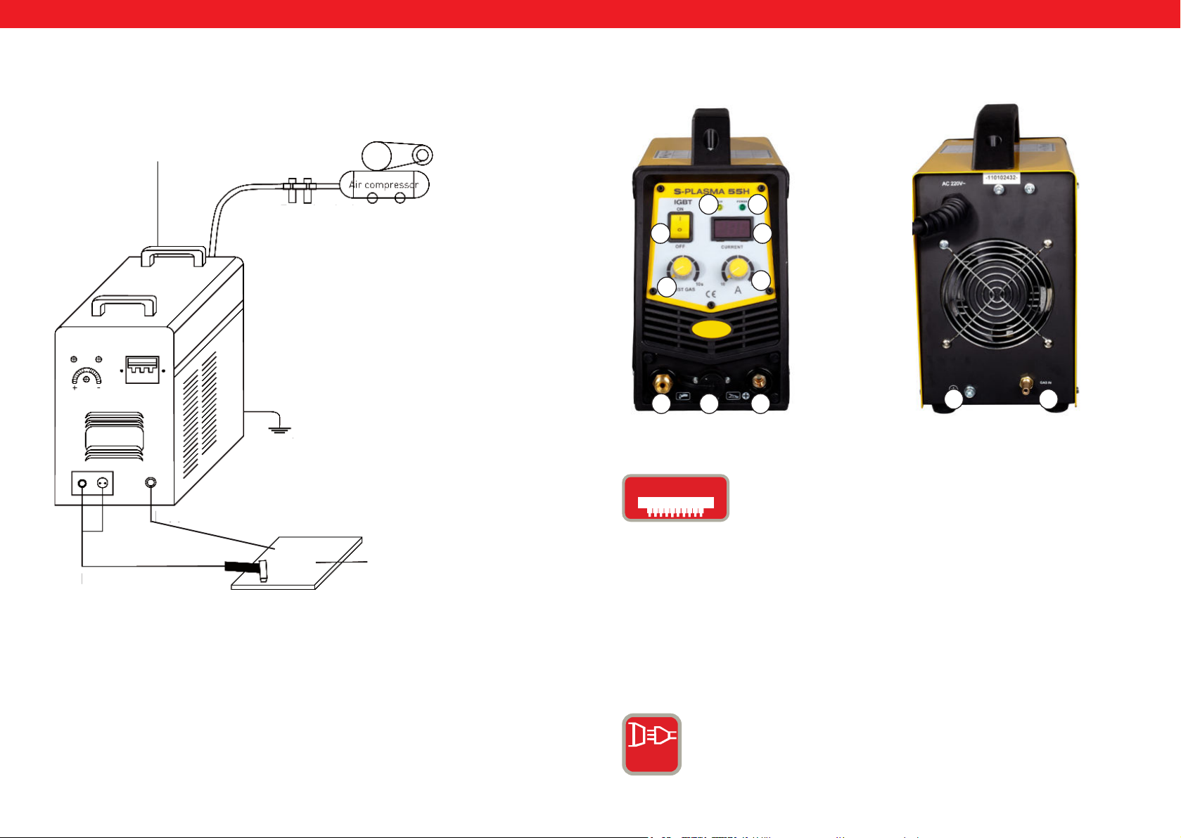
HUHU
Tápkábel
S-Plasma 55H KAPCSOLÁSI RAJZ
Kompresszor
nyomáscsökkentő
Ház földelése
Levegő
kompresszor
S-PLASMA 55 H
ELÖLNÉZET
0
11
HÁTULNÉZET
32
4
1
567
9 8
IGbT
Testkábel
Munkadarab
Vágópisztoly
A szigetelt vezérlőelektródás bipoláris tranzisztor (ang.
Insulated Gate Bipolar Transistor, röviden: IGBT) egy félvezető
elem, amelyet nagy teljesítményű áramkörökben használnak,
mivel ötvözi a bipoláris tranzisztor előnyeit (pl. nagy
vezetőképesség, nagy ellenállási feszültség, tartós teljesítmény
hegesztőgépekben) és a szigetelt kapuelektródával ellátott
térvezérlésű tranzisztor előnyeit (szinte áramveszteség
nélküli vezérlés). A rövidzárlattal szembeni ellenállás
szintén előny, mivel az IGBT korlátozza a terhelési áramot.
Az IGBT áramkörök a függőleges MOSFET áramkörök
továbbfejlesztését jelentik
NORMÁL ÁRAM: hegesztőgépet tápellátása egy fázisból
történik (230V +/- 10%)
1 PH
160 161
Rev. 04.04.2022 Rev. 04.04.2022
Page 82
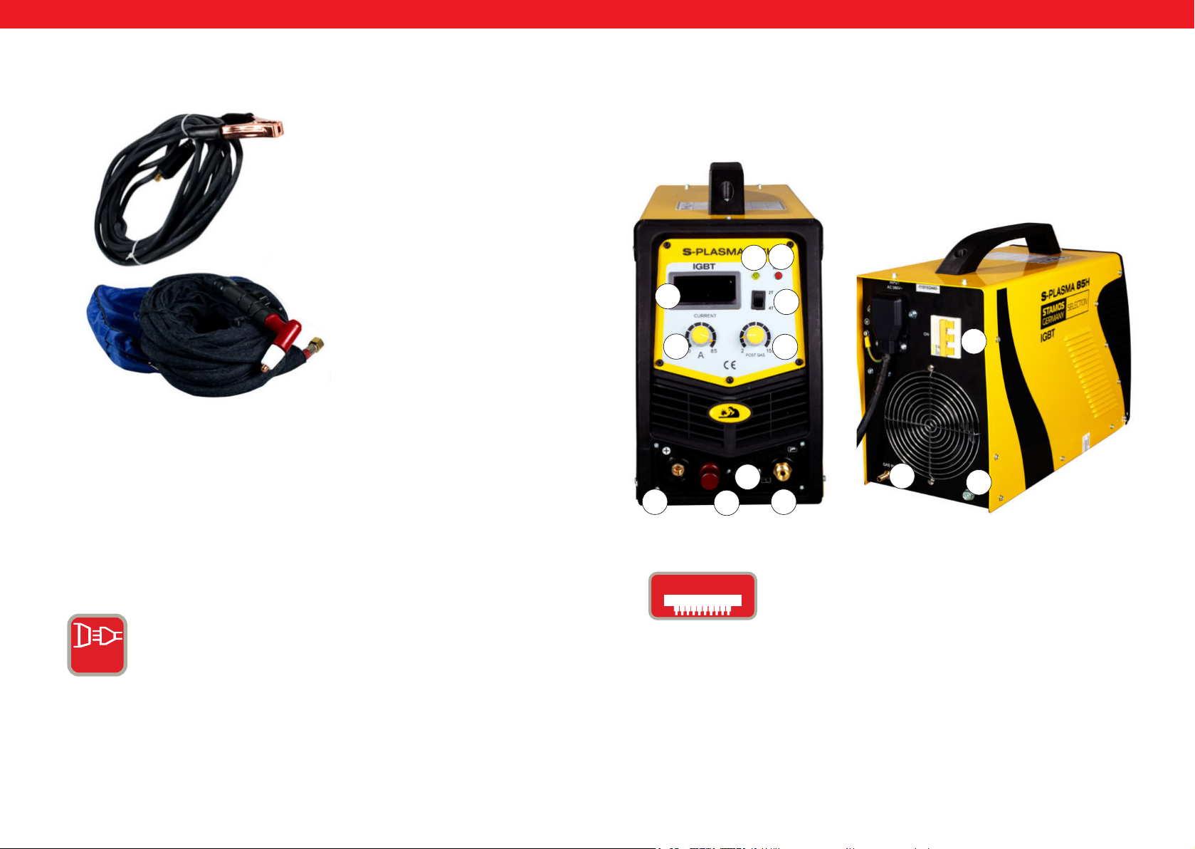
HUHU
PLAZMAVÁGÓ TARTOZÉKOK
1
1. Testcsipesz
2. Plazmapisztoly
2
S-PLASMA 85H | S-PLASMA 85CNC
ELÖLNÉZET
19
2
4
1
12
11
HÁTULNÉZET
0
20
5
20. Kizárólag az S-PLASMA 85CNC esetében
S-PLASMA 85H / S-PLASMA 85CNC HÁLÓZATI CSATLAKOZÁS
STARKSTROM: = Ezek az eszközök háromfázisú
csatlakozással működnek (400V +/- 10%)
6
IGbT
3 PH
162 163
Rev. 04.04.2022 Rev. 04.04.2022
7
A szigetelt vezérlőelektródás bipoláris tranzisztor (ang.
Insulated Gate Bipolar Transistor, röviden: IGBT) egy félvezető
elem, amelyet nagy teljesítményű áramkörökben használnak,
mivel ötvözi a bipoláris tranzisztor előnyeit (pl. nagy
vezetőképesség, nagy ellenállási feszültség, tartós teljesítmény
hegesztőgépekben) és a szigetelt kapuelektródával ellátott
térvezérlésű tranzisztor előnyeit (szinte áramveszteség
nélküli vezérlés). A rövidzárlattal szembeni ellenállás
szintén előny, mivel az IGBT korlátozza a terhelési áramot.
Az IGBT áramkörök a függőleges MOSFET áramkörök
továbbfejlesztését jelentik
8
9
Page 83
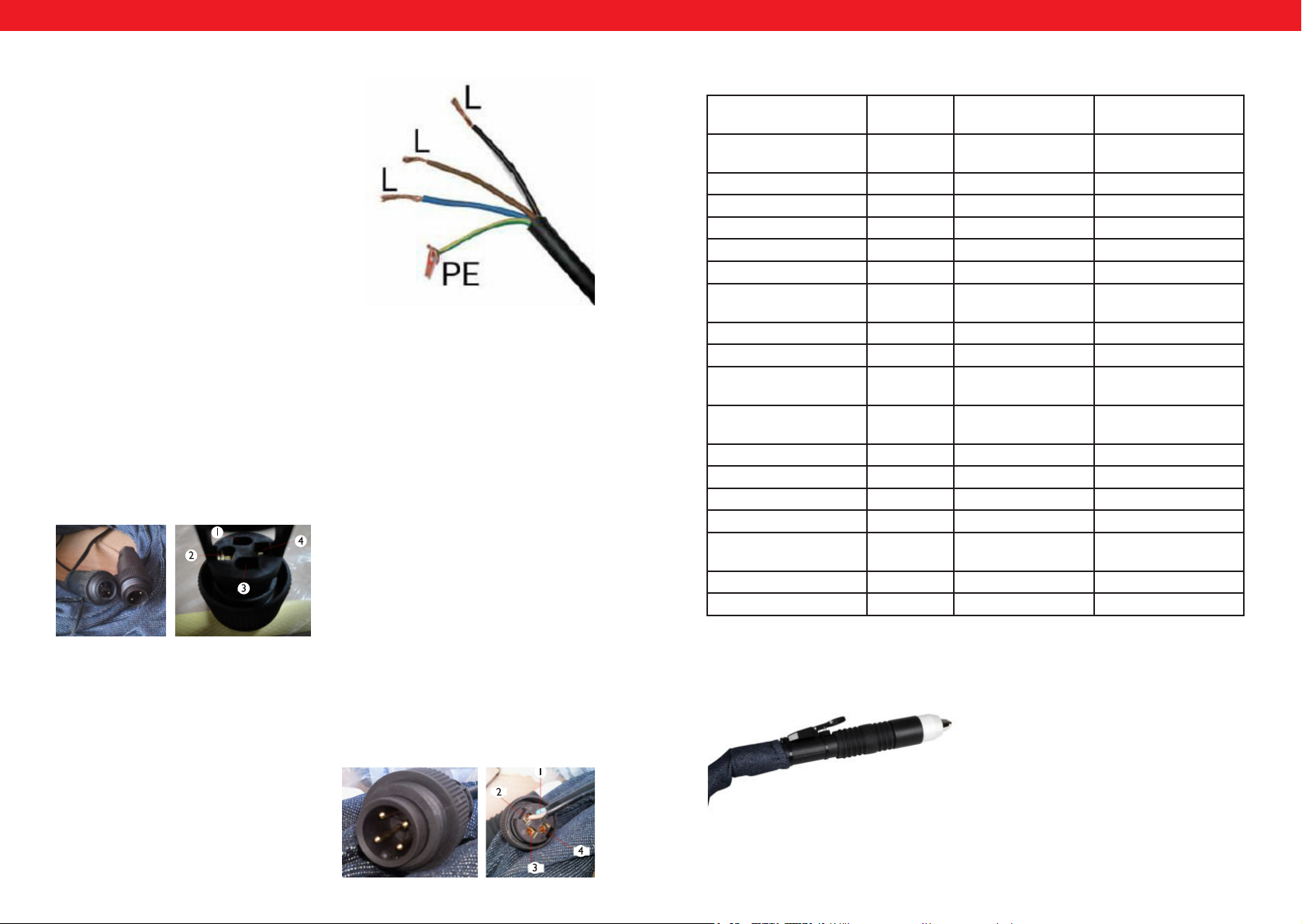
PODŁĄCZENIE CNC
Aby podłączyć przecinarkę do maszyny CNC należy podłączyć dwa piny we
wtyczce: pin 3 oraz pin 4. CNC będzie działać w przypadku gdy maszyna CNC
będzie włączona, w przeciwnym przypadku będzie działało tylko cięcie ręczne.
Pin 1 oraz 2 są podłączone fabrycznie i jest to podłączenie tylko i wyłącznie do
cięcia ręcznego:
HUHU
S-Plasma 85H + 125H / 85CNC + 125CNC üzembe helyezése
Hálózati csatlakozás A sárga-zöld vezeték a
PE védővezeték csatlakoztatására szolgál. A
három fázis (fekete, barna és kék) bármilyen
módon csatlakoztatható az L1, L2 és L3-hoz.
Ezt a munkát csak szakképzett villanyszerelő
végezheti.
FIGYELEM!
Az elektroenergetikai csatlakozással rendelkező hegesztőberendezéseket kizárólag
szakképzett villanyszerelő helyezheti üzembe!
CNC S-PLASMA 125CNC ÜZEMBE HELYEZÉSE
A vágónak a CNC géphez történő kapcsolásához a dugó két pinjét kell csatlakoztatni:
Pin 4: pozitív pólus
Pin 2: negatív pólus
Részletes műszaki adatok
S-Plasma
55H
Hálózati feszültség 230V
1-fázis
Frekvencia 50Hz 50Hz 50Hz
Bemeneti áram 16A 19 A 20 A
Üresjárati feszültség 230 V 280 V 300 V
Védelmi besorolás IP20S IP20S IP21S
Szigetelési besorolás F F F
Túlfeszültség elleni
védelem
Hűtés Ventilátor Ventilátor Ventilátor
Mágneszár Igen Igen Igen
Bekapcsolási ciklus max.
áramerősség A esetén
Áramerősség A 100%-os
bekapcsolási időnél
Vágóáram 10-55 A 20-85 A 10-125 A
Ív keletkezés Érintkezéses Érintésmentes Érintésmentes
Vágás vastagsága 17 mm 27 mm 34 mm
Vágás szélessége 1 mm 1,2 mm 1,4 mm
kompresszor csatlakozás 4,5 bar,30-
Súly (nettó) 9.4 kg 19,5 kg 30 kg
Méretek h./sz./m. (mm) 530/380/380 660/370/450 660/370/450
Igen Igen Igen
60% 60% 60%
42,6 65,8 96,8
100 1/min.
S-Plasma 85H és
S-Plasma 85CNC*
400V
3-fázis
5,5 bar,
175 l/min.
S-Plasma 125H és
S-Plasma 125CNC*
400V
3-fázis
7 bar
250 l/min
* FIGYELEM! A S-Plasma 85CNC és S-Plasma 125CNC modellek további CNC
csatlakozóval rendelkeznek. Emellett ez a két plazmavágó modell egyenes pisztollyal
CNC S-PLASMA 85CNC ÜZEMBE HELYEZÉSE
van ellátva:
A vágónak a CNC géphez történő kapcsolásához a dugó két pinjét kell csatlakoztatni:
pin 3 és pin 4. A CNC akkor fog működni, amikor a CNC gép be van kapcsolva,
különben csak a kézi vágás fut. Az 1-es és 2-es pin gyárilag van csatlakoztatva, és ez
csak és kizárólag kézi vágáshoz használható:
Pin 3: pozitív pólus
Pin 4: negatív pólus
164 165
Rev. 04.04.2022 Rev. 04.04.2022
Page 84
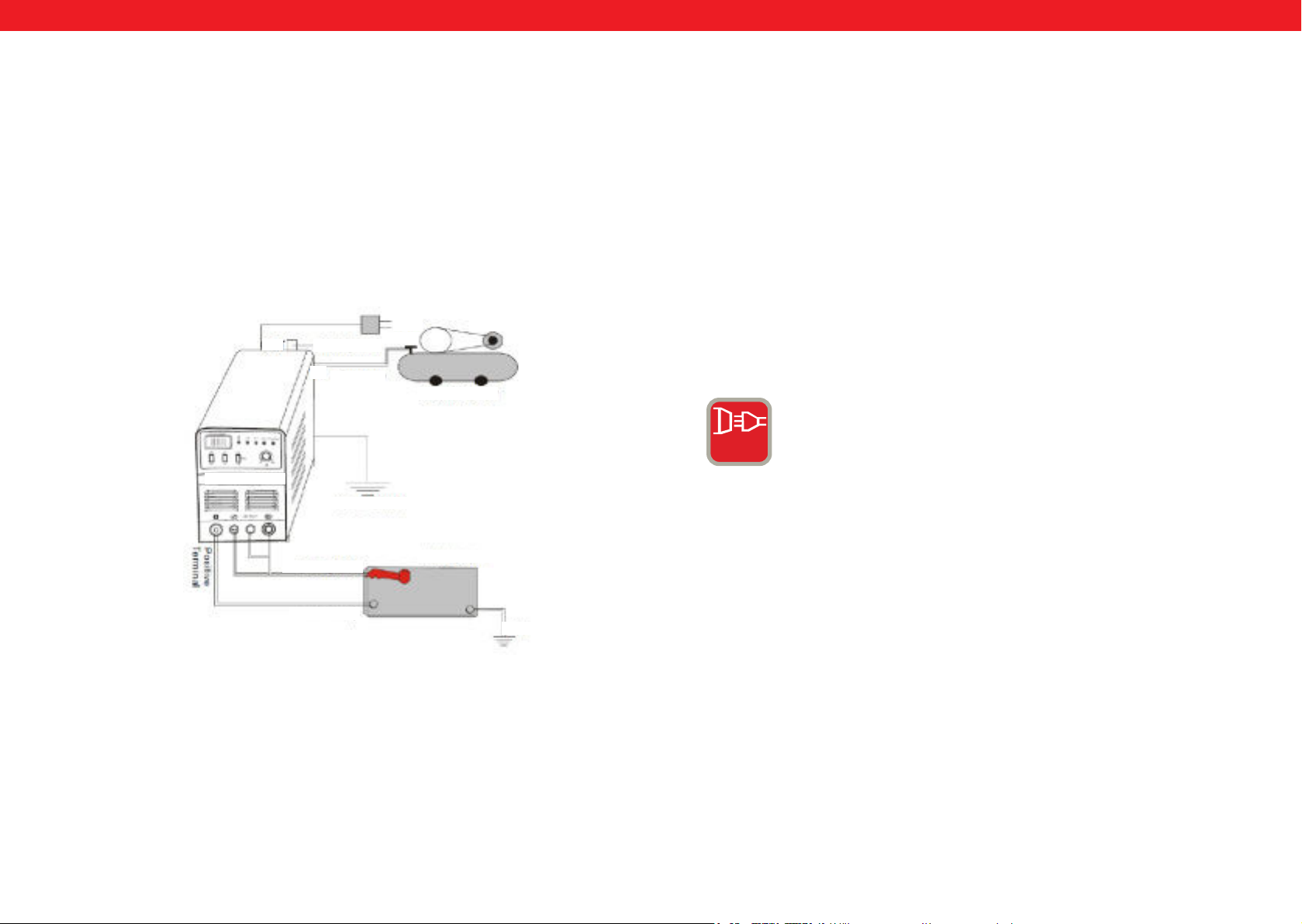
HUHU
Üzembe helyezés
1. Minden plazmavágóhoz tartozik egy hálózati kábel, melyet a plazmavágó
bemeneti feszültségének megfelelő áramforráshoz kell csatlakoztatni.
2. Az oxidáció elkerülése érdekében a tápkábelt megfelelően kell csatlakoztatni
a csatlakozóhoz vagy a kapcsolóhoz. Amennyiben lehetséges, ellenőrizze
mérőműszerrel, hogy a feszültség a megfelelő tartományban van-e.
A vezetékek csatlakoztatása (bekötési rajz)
400V
Tápkábel
Kompresszor
nyomáscsökkentő
IN
Levegő kompresszor
S-Plasma 125H
Ház földelése
Használat
Kapcsolja be a kapcsolót a hátsó panelen, a lámpa kigyullad és megjelenik az
aktuális áramérték.
Állítsa be a követelményeknek megfelelő gáznyomást, és nyissa ki a kompresszor
szelepet. Nyomja meg a vezérlőgombot a vágópisztolyon, a szelep aktiválódik,
ezután látható és hallható az ív. A vágósugarat a munkadarab vastagságának
megfelelően állítsa be. Helyezze a vágópisztoly rézfúvókáját a munkadarabra
(fényív esetén állítsa a rézfúvókát kb. 2 mm-re a munkadarabtól), nyomja meg
a pisztoly gombját, amíg az ív létre nem jön, emelje meg kissé, kb. 1 mm-re a
munkadarabtól a vágópisztolyt, és kezdje el a vágást.
3 PH
STARKSTROM = Ezek az eszközök háromfázisú csatlakozással
működnek (400V +/- 10%)
Testkábel
Munkadarab
Vágópisztoly
Földelés
166 167
Rev. 04.04.2022 Rev. 04.04.2022
Page 85
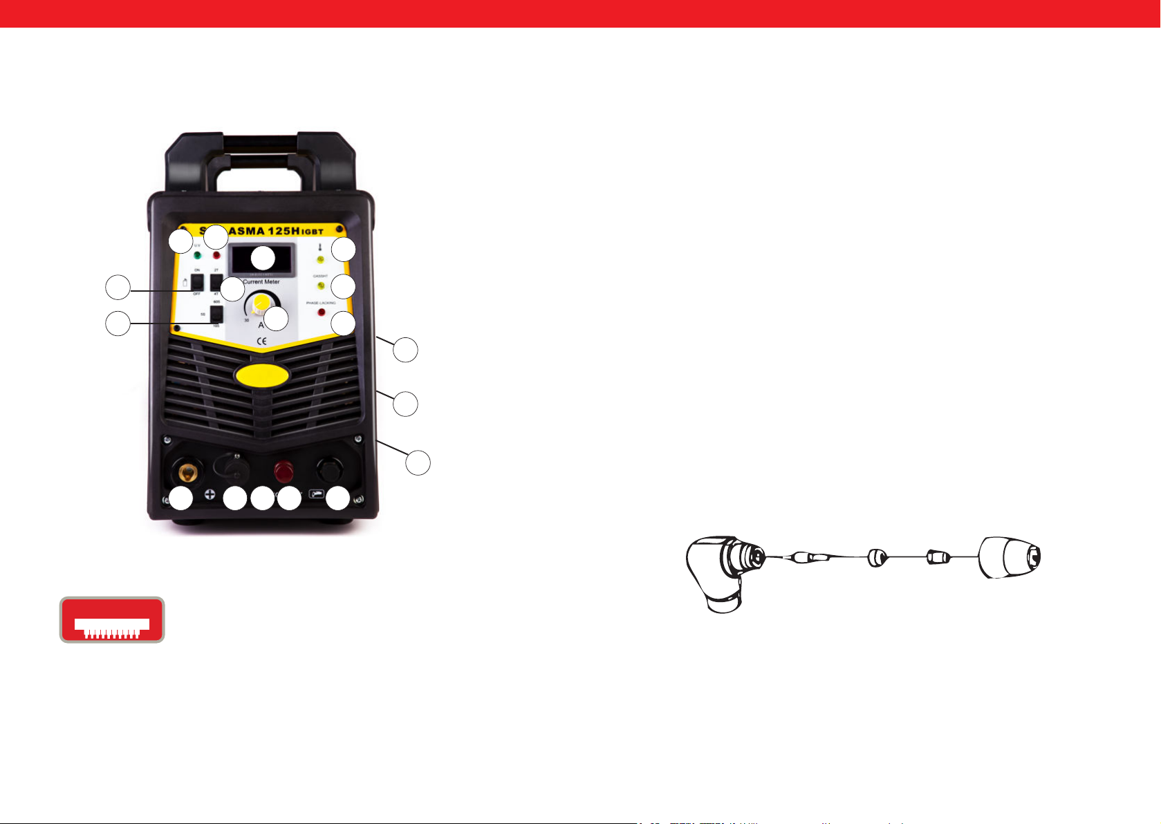
HUHU
S-PLASMA 125H | S-PLASMA 125CNC
17
16
4
15
14
7
13
1
10 6 5
20
2
18
19
ÜZEMBE HELYEZÉS
A. Kicsomagolás
Csomagolja ki az összes alkatrészt a csomagolásból, és győződjön meg arról, hogy a
szállítólevélen lévő összes tételt megkapta.
B. Munkakörnyezet
Bizonyosodjon meg arról, hogy a munkaterületen megoldott a jó szellőzés. A készüléket
tengely ventilátorral hűtik, amely egy elektronikus rendszer segítségével levegőáramot
biztosít a hátsó részen.
(Megjegyzés: A házat úgy kell telepíteni, hogy a szellőzőnyílások közelebb legyenek a
készülék elejéhez.) Hagyjon körülbelül 15 cm szabad helyet az elülső részen, és 15 cm-t
mindkét oldalon a tisztításhoz. Ha az egységet megfelelő hűtés nélkül működtetik, a
bekapcsolási idő jelentősen lerövidül.
C. Kábelbemeneti csatlakozás
Minden eszköz rendelkezik egy fő tápkábellel, amely biztosítja a készülék megfelelő
0
áramerősségét és feszültségét. A gép súlyos károsodásához vezethet, ha a gépet olyan
áramforráshoz csatlakoztatja, amely meghaladja a szükséges paramétereket, vagy ha a
fázis nem megfelelő. Erre a garanciális feltételek nem vonatkoznak, és ez a felhasználó
hibájának minősül.
9
D. Plazmapisztoly csatlakozása
A plazmapisztolyt úgy kell csatlakoztatni az eszközhöz, hogy a pisztolyt a gép elején
8
lévő pisztolytartó csatlakozóhoz csavarja. A szerkezetet csavarhúzóval enyhén meghúzva kell rögzíteni. Ne húzza meg túlzottan.
A PLAZMAPISZTOLY FELÉPÍTÉSE
20. Kizárólag a S-PLASMA 125CNC modell esetén
IGbT
168 169
A szigetelt vezérlőelektródás bipoláris tranzisztor (ang.
Insulated Gate Bipolar Transistor, röviden: IGBT) egy félvezető
elem, amelyet nagy teljesítményű áramkörökben használnak,
mivel ötvözi a bipoláris tranzisztor előnyeit (pl. nagy
vezetőképesség, nagy ellenállási feszültség, tartós teljesítmény
hegesztőgépekben) és a szigetelt kapuelektródával ellátott
térvezérlésű tranzisztor előnyeit (szinte áramveszteség
nélküli vezérlés). A rövidzárlattal szembeni ellenállás
szintén előny, mivel az IGBT korlátozza a terhelési áramot.
Az IGBT áramkörök a függőleges MOSFET áramkörök
továbbfejlesztését jelentik
Rev. 04.04.2022 Rev. 04.04.2022
Elektróda Forgógyűrű Fúvóka Kerámia védőkupak
Page 86

HUHU
A. A plazmapisztoly felhelyezése
Helyezze a plazmapisztolyt a védőkupakkal felfelé, és csavarja le. (A védőkupak tartja
a hegyet, a forgó kerámiagyűrűt és az elektródát.) Távolítsa el a hegyet, a forgó
kerámiagyűrűt és az elektródát. Szerelje vissza az elektródát, a forgó kerámiagyűrűt és
a hegyet. Szükség esetén cserélje ki a kopott alkatrészeket. Helyezze a védőkupakoz
a plazmapisztoly végére, és csavarja rá kézzel, amíg stabil nem lesz. Amennyiben a
felhasználó ellenállást tapasztal ezen eljárás során, a munka megkezdése előtt ellenőrizze
a meneteket és a különböző alkatrészek helyét.
Figyelem!
Egyes plazmapisztolyok esetében, amelyek nem rendelkeznek átkapcsolható
elektródával, a megfelelő elektromos csatlakozás biztosítása érdekében az elektródát
kiegészítő fogóval kell meghúzni.
HASZNÁLAT
A. Előkészületek
Állítsa a kapcsolót ON állásba Helyezkedjen úgy, hogy könnyen leolvashassa a készülék
légnyomását. Nyomja meg a plazmapisztoly gombját (ekkor elindul a levegőáramlás a
pisztolyból), állítsa a nyomásszabályozó szelepet kb. 6-7 bar értékre, majd engedje el
plazmapisztoly gombját.
Figyelem!
A légnyomás 5 és 8 bar közötti tartományban engedélyezett. Különböző próbák
végezhetők, de ügyelni kell arra, hogy a légnyomás ne csökkenjen le túlságosan, mert
ez károsíthatja a kopóalkatrészeket. Rögzítse a földelés csipeszeket a munkadarabon.
A csipeszt a munkadarab fő részéhez csatlakoztassa, és ne ahhoz a részhez, amelyet
eltávolítanak.
2. Hetente végzendő karbantartás
Ellenőrizze, hogy a szellőzés megfelelően működik-e. Távolítsa el vagy porszívózza
össze az összes port vagy törmeléket az egész gépből, beleértve a légszűrőket is.
3. Távtartó vágás
Bizonyos esetekben előnyös lehet, ha a pisztoly hegyét a munkadarab felett kb. 1/16 „1/8“ tartják, így a hegybe visszavezetett anyag csökkentésével folyik a vágás, ami maximális
behatolást eredményez a vágott anyagba. Távtartó vágást akkor érdemes alkalmazni, ha
elválasztó vagy hasító vágást végeznek. Ezt a technikát fémlemez vágásakor javasolt
alkalmazni, hogy minimalizálható legyen fémforgács keletkezése, amely megrongálhatja
a hegyet.
4. Fúrás
Fúráskor helyezze a hegyet kb. 3,2 mm-rel a munkadarab fölé. Tartsa a pisztolyt enyhe
szögben, hogy távol tartsa a szikrákat a pisztoly hegyétől és a kezelőtől. Indítsa el
a fő ívet és engedje le a pisztoly hegyét addig, amíg a fő ív létrejön és szikrák nem
keletkeznek. Ellenőrizze a fúrást egy próbadarabon, és ha a folyamat megfelelő, hajtsa
végre az előre meghatározott vonalon.
KARBANTARTÁS
Ellenőrizze, hogy a plazmapisztoly nem sérült-e, nincs-e rajta repedés vagy szigetelés
nélküli kábel. A készülék használata előtt cserélje ki vagy javítsa meg. Az erősen
kopott fúvóka / plazmapisztoly hegy lassabb sebességet, feszültségesést és egyenetlen
szétválasztást okoz. Az erősen kopott plazmapisztoly hegy / fúvóka jele a megnyújtott
vagy túl nagy fúvóka nyílás. Az elektróda külső része 3,2 mm-nél nem lehet mélyebben.
Amennyiben a megadott méretnél többet kopott, cserélje ki. Amennyiben a kupak nem
rögzíthető, ellenőrizze a menetet.
B. Vágás
1. Drag típusú vágás
Helyezze a plazmapisztoly hegyét a munkadarabra, nyomja meg a gombját, és mozgassa
pisztoly hegyét, amíg az hozzá nem ér a munkadarabhoz, és létre nem jön a vágóív. A
vágóív létrehozása után mozgassa a plazmapisztolyt a kívánt irányba úgy, hogy a pisztoly
hegye mindig kis szögbet zárjon be a munkadarabbal, miközben azzal érintkezik. Ezt
a munkamódszert dragnak nevezik. Kerülni kell a túl gyors mozgásokat. A túl gyors
Figyelem!!! A fúvóka és az elektróda cseréjekor mindenképp ellenőrizze,
hogy a készülék ki van-e kapcsolva.
Ellenőrzés
1. A berendezést mindig biztonságosan földelni kell.
2. Ellenőrizze, hogy minden csatlakozás megfelelően van-e csatlakoztatva.
3. Ellenőrizze, hogy a tápkábel megfelelő feszültséget biztosít-e.
4. Ügyeljen arra, hogy a kábel és a tömlők ne legyenek sérültek vagy kopottak.
mozgást szikrák jelzik, amelyek a munkadarab felső oldalán keletkeznek. Olyan ütemben
mozgassa a plazmapisztolyt, hogy a szikrák a munkadarab alsó oldalán összpontosuljanak,
és a művelet folytatása előtt győződjön meg arról, hogy az anyag teljesen szétvált. A
drag típusú vágás sebességét igény szerint igazítsa.
170 171
Rev. 04.04.2022 Rev. 04.04.2022
Page 87

Umwelt- und Entsorgungshinweise
Hersteller an Verbraucher
Sehr geehrte Damen und Herren,
gebrauchte Elektro- und Elektronikgeräte dürfen gemäß europäischer Vorgaben [1] nicht zum unsortierten Siedlungsabfall
gegeben werden, sondern müssen getrennt erfasst werden. Das Symbol der Abfalltonne auf Rädern weist auf die Notwendigkeit
der getrennten Sammlung hin. Helfen auch Sie mit beim Umweltschutz. Sorgen Sie dafür, dieses Gerät, wenn Sie es nicht mehr
weiter nutzen wollen, in die hierfür vorgesehenen Systeme der Getrenntsammlung zu geben.
In Deutschland sind Sie gesetzlich [2] verpichtet, ein Altgerät einer vom unsortierten Siedlungsabfall getrennten Erfassung
zuzuführen. Die öffentlich - rechtlichen Entsorgungsträger (Kommunen) haben hierzu Sammelstellen eingerichtet, an denen
Altgeräte aus privaten Haushalten ihres Gebietes für Sie kostenfrei entgegengenommen werden. Möglicherweise holen die
rechtlichen Entsorgungsträger die Altgeräte auch bei den privaten Haushalten ab.
Bitte informieren Sie sich über Ihren lokalen Abfallkalender oder bei Ihrer Stadt- oder Gemeindeverwaltung über die in Ihrem
Gebiet zur Verfügung stehenden Möglichkeiten der Rückgabe oder Sammlung von Altgeräten.
[1] RICHTLINIE 2002/96/EG DES EUROPÄISCHEN PARLAMENTS UND DES RATES
ÜBER ELEKTRO- UND ELEKTRONIK - ALTGERÄTE
[2] Gesetz über das Inverkehrbringen, die Rücknahme und die umweltverträgliche Entsorgung
von Elektro- und Elektronikgeräten (Elektro- und Elektronikgerätegesetz - ElektroG).
Utylizacja produktu
Produkty elektryczne i elektroniczne po zakończeniu okresu eksploatacji wymagają segregacji i oddania ich do wyznaczonego punktu odbioru. Nie wolno wyrzucać produktów elektrycznych razem z odpadami gospodarstwa domowego. Zgodnie
z dyrektywą WEEE 2012/19/UE obowiązującą w Unii Europejskiej, urządzenia elektryczne i elektroniczne wymagają segregacji i utylizacji w wyznaczonych miejscach. Dbając o prawidłową utylizację, przyczyniasz się do ochrony zasobów naturalnych
i zmniejszasz negatywny wpływ oddziaływania na środowisko, człowieka i otoczenie. Zgodnie z krajowym prawodawstwem,
nieprawidłowe usuwanie odpadów elektrycznych i elektronicznych może być karane!
For the disposal of the device please consider and act according to the national and local rules and regulations.
172
CONTACT
expondo Polska sp. z o.o. sp. k.
ul. Nowy Kisielin-Innowacyjna 7
66-002 Zielona Góra | Poland, EU
e-mail: [email protected]
expondo.com
Rev. 04.04.2022
 Loading...