

Stamina Magnetic Fusion 7100 Bike, Fusion 7100, 15-7100B Owner's Manual
Model#: 15-7100B
ST AMINA PRODUCTS
MADE IN CHINA
Product May V ary Slightly
From Pictured.
Exercise can present a health
risk. Consult a physician
before beginning any exercise
program with this equipment.
If you feel faint or dizzy,
immediately discontinue use
of this equipment. Serious
bodily injury can occur if this
equipment is not assembled
and used correctly. Serious
bodily injury can also occur if
all instructions are not followed.
Keep others and pets away
from equipment when in use.
Always make sure all bolts a nd
nuts are securely tightened
prior to each use. Follow all
safety instructions in this
manual.
When calling for parts or
service, please specify the
following number
:
WA R NING
CAUTION:
Weight on this product should not exceed 300 lbs.
Owner's
Ma nual
2009, 1 1
2009 Stamin a Products, Inc.
2040 N. Alliance, Springfield, MO 65803
Customer Service
1 (800) 375-7520
www.staminaproducts.com
This Product is Produced Exclusively by

T ABLE OF CONTENTS
Safety Instructions 2
Before You Begin 4
Equipment Warning & Notice Labels 5
Hardware Identification Chart 6
Assembly Instructions 7
Set Up Instructions 13
Operational Instructions 14
Computer Instructions 15
Storage 18
Maintenance 18
Conditioning Guidelines 19
Warm-Up and Cool-Down 20
Warranty 21
Product Parts Drawing 22
Parts List 23
Notes 25
Fax/Mail Ordering Form 26
Page Page
SAFETY INSTRUCTIONS
To reduce the risk of serious injury, read the following Safety Instructions before
using the Magnetic Fusion 7100 Bike.
WARNING:
2
Before starting any exercise or conditioning program you should consult with your personal
physicia n to see if you require a complete physical exa m. This is e specially i mporta nt if you
are over the age of 35, have never exercised before, are pregnant, or suffer from any
illness. READ AND FOLLOW THE SAFETY PRECAUTIONS. FAILURE TO FOLLOW
THESE INSTRUCTIONS CAN RESULT IN SERIOUS BODILY INJURY.
WARNING:
1.
2.
3.
4.
5.
6.
7.
8.
9.
10.
11.
12.
13.
14.
15.
16.
17.
18.
19.
20.
21.
22.
23.
24.
Read all warnings posted on the Magnetic Fusion 7100 Bike.
The Magnetic Fusion 7100 Bike should only be used after a thorough review of the Owner's Manual.
We re commend that two people be availa ble f or assembly of this product.
Keep children away from the Magnetic Fusion 7100 Bike. Do not allow children to use or play on the Magnetic
Fusion 7100 Bike. Keep children and pets away from the M agnetic Fusion 7100 Bike when it is in use.
The M agnetic Fusion 7100 Bike is not a freewheeling exercise bike; therefore, pedal speed should be reduced
in a controlled manner to prevent injury from spinning pedals.
Make sure the Magnetic Fusion 7100 Bike is properly assembled and that all nuts and bolts are tightened
before use.
It is recommended that you place this exercise equi pment on an equipment mat.
Set up and operate the Magnetic Fusion 7100 Bike on a solid level surface. Do not position the Magnetic
Fusion 7100 Bike on loose rugs or uneven surfaces.
Make sure that adequate space is available for access to and around the Magnetic Fusion 7100 Bike.
Adjust the LEVELING CAPS(57) and STAND(60) so that the Magnetic Fusion 7100 Bike sits on the floor
without rocking. See page 13 for detailed leveling instructions.
Before using, inspect the M agnetic Fusion 7100 Bike for worn or loose components, a nd securely tighten or
replace any worn or loose components prior to use.
Before using, always check the SEA T FRAME(7) to be sure it is secure. The ADJUSTMENT KNOB(51) must
be inserted into one of the holes in the REAR FRAME(5) and securely tightened.
Each user should a djust the seat per in structions on page 14.
Do not attempt to adjust the seat while you are on the Magnetic Fusion 7100 Bike.
Consult a physicia n prior to commencing an exercise progra m and follow his/her re commendations in developing
your fitness progra m. If at a ny time during exercise you feel faint, dizzy, or experience pain, stop and consult
your physician.
Follow your physician's recommendation s in developing your own personal f itness program.
Always choose the workout which best fits your physical strength and flexibility level. Know your li mits and train
within them. Always use common sen se when exercising.
Do not wear loose or dangling clothing while using the Magnetic Fusion 7100 Bike.
Never exercise in bare feet or socks; always wear proper footwear such a s running, wal king, or cross training
shoes that fit well, provide foot support, and feature non-skid rubber soles.
Care should be taken in mounting or dismounting the Magnetic Fusion 7100 Bike.
The Magnetic Fusion 7100 Bike should not be used by person s weighing over 300 pounds.
The Magnetic Fusion 7100 Bike should be used by only one person at a time.
Do not ride the Magnetic Fusion 7100 Bike while standing up.
The Magnetic Fusion 7100 Bike is for consumer use only. It is not for use in public or semipublic facilitie s.

THANK YOU FOR PURCHASING THE
Magnetic Fusion 7100 Bike
To help you get started, we have pre-assembled most of your
Magnetic Fusion 7100 Bike at the factory with the exception
of those few parts left unassembled for shipping purposes.
Simply follow the few assembly instructions set forth in this manual.
With regular workouts, you will be getting your body into sha pe
and be on your way to achieving a happier and healthier lifestyle.
Should you have any que stions,
please call our Customer Service Department toll-free number,
1 (800) 375-7520
Monday - Thursday, 7:30 A.M. - 5:00 P.M., Central Time.
Friday, 8:00 A.M. - 3:00 P.M., Central Time.
CALL US FIRST
Customer Service
1(800) 375-7520
www.staminaproducts.com
TELEPHONE
CUSTOMER SERVICE
Tel: 1 (800) 375-7520
FAX
CUSTOMER SERVICE
Fax: (417) 889-8064
MAIL
STAMINA PRODUCTS, INC.
A TT N: Customer Service
P .O. Box 1071
Springfield, MO. 65801-1071
ONLINE
CUSTOMER SERVICE
customerservice@staminaproducts.com
www.staminaproducts.com
3
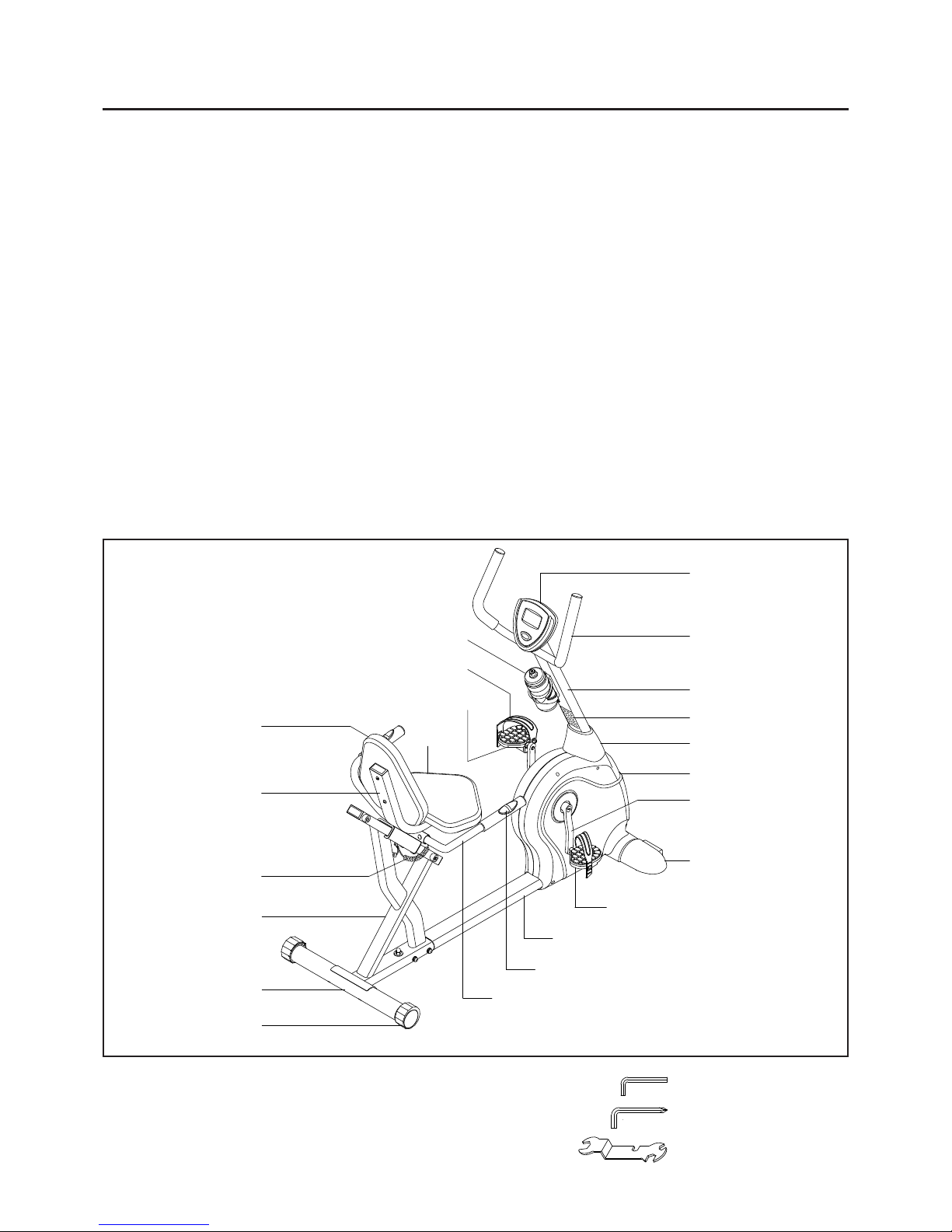
BEFORE YOU BEGIN
4
Seat
Rear Stabilizer
Right Foot Cap
Right Crank
Right Cover
Back Cushion
Leveling Cap
Seat Frame
Right Pedal
Left Pedal
Upright Sleeve
Front Frame
Computer
Warning Label
Thank you f or choosing the Magnetic Fusion 7100
Bike. We take great pride in producing this quality
product and hope it will provide ma ny hours of quality
exercise to make you feel better, look better, and
enjoy life to its fullest.
It's a proven fact that a regular exercise program
can improve your physical and mental health. Too
often, our busy lifestyles limit our ti me and opportunity
to exercise. The Magnetic Fusion 7100 Bike
provides a convenient and simple method to begin
your assault on getting your body in shape and
achieving a happier and healthier lifestyle.
Before reading further, please review the drawing
below and familiarize yourself with the parts that are
labeled.
Read this manual carefully before using the
Magnetic Fusion 7100 Bike.
Although Stamina constructs its products with the
finest materials and uses the highest standards of
manufacturing and quality control, there can
sometimes be missing parts or incorrectly sized
parts. If you have any questions or problems with
the parts included with your Magnetic Fusion 7100
Bike, please do not return the product. Contact us
FIRST!
If a part is missing or defective, please call us toll
free at 1-800-375-7520 (in the U.S.). Our Customer
Service Staff is available to a ssist you from 7:30 A.M.
to 5:00 P.M. (Central Time) Monday through
Thursday and 8:00 A.M. to 3:00 P.M. (Central Time)
on Friday.
If you would like to contact us online, go to our
website at www .stamin aproducts.com a nd a ccess the
Customer Service section.
Be sure to have the name and model number of
the product available when you contact us.
Upright
Rear Frame
Pulse Coil Wire
Left Pedal Strap
THE FOLLOWING TOOLS ARE INCLUDED FOR ASSEMBLY :
Allen Wrench (5mm)
Allen Wrench (6mm)
Multi-opening Wrench
Handrail
Water Bottle
Handlebar
Pulse Sensor
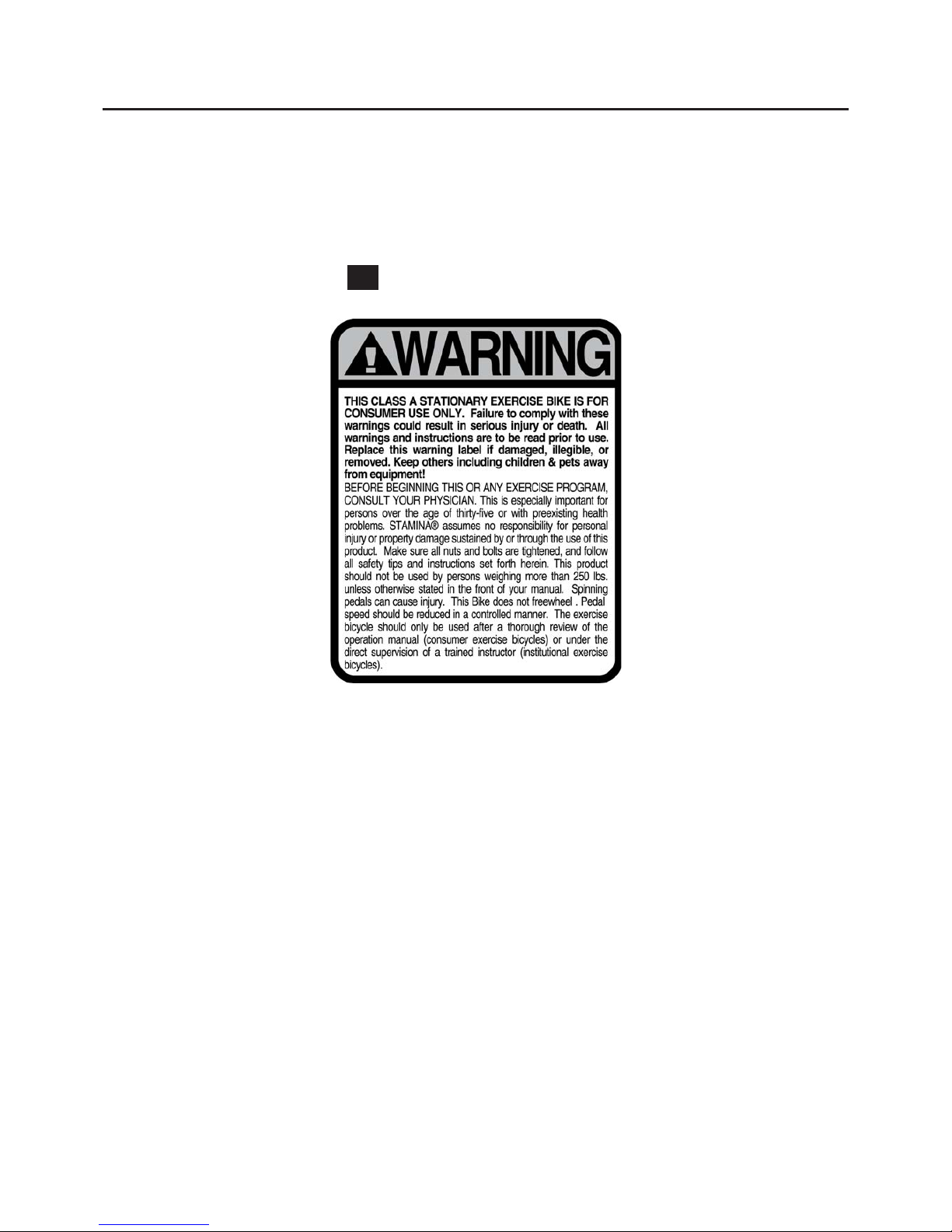
EQUIPMENT WARNING & NOTICE LABELS
This chart is provided to help identify the warning & notice labels on the Magnetic Fusion 7100 Bike.
Please take a moment to familiarize yourself with all of the warning & notice labels.
Label is larger than actual size
WAR NING LABEL(95)
W1
5
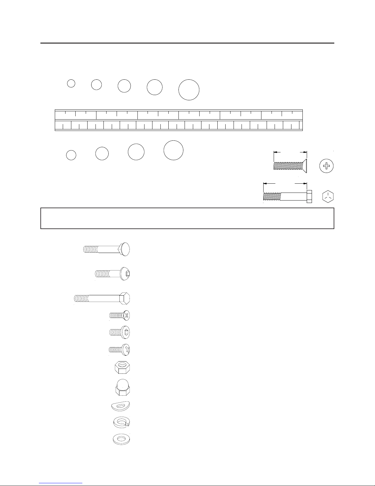
HARDWARE IDENTIFICATION CHART
This chart is provided to help identify the hardware used in the a ssembly process. Pla ce the washers or the
ends of the bolts or screws on the circles to check for the correct di ameter. Use the small scale to check the
length of the bolts and screws.
NOTICE: The length of all bolts and screws, except those with flat heads,
is mea sured from below the hea d to the end of the bolt or screw .
Flat head bolts and screws are measured from the top of the
head to the end of the bolt or screw.
mm.
in.
INCHES
MILLIMETERS
11/2021/2 31/2 41/2 51/2 61/2
0 10 20 30 40 50 60 70 80 90 100 110 120 130 140 150
6 8 10 12
3/16" 5/16" 1/2"3/8"1/4"
length
length
After unpacking the unit, open the hardware bag and make sure that you have all the following items.
Some hardware may be already attached to the part.
6
Part No. and Description Qty
91 Washer (M8) 2
92 Washer (M10) 1
62 Carriage Bolt (M8 x 1.25 x 45mm) 2
63 Carriage Bolt (M8 x 1.25 x 75mm) 2
64 Bolt, Button Hea d (M8 x 1.25 x 40mm) 3
65 Bolt, Button Hea d (M8 x 1.25 x 53mm) 2
66 Bolt, Button Hea d (M10 x 1.5 x 20mm) 4
67 Bolt, Button Hea d (M10 x 1.5 x 53mm) 2
68 Bolt, Hex Hea d (M8 x 1.25 x 80mm) 1
69 Bolt, Flat Hea d (M6 x 1 x 12mm) 2
73 Bolt, Round Head (M6 x 1 x 15mm) 4
75 Screw, Round He a d (M4 x 0.7 x 15mm) 6
80 Nut (M8 x 1.25) 1
84 Acorn Nut (M8 x 1.25) 4
85 Acorn Nut (M10 x 1.5) 1
86 Arc Washer (M8) 4
87 Arc Washer (M10) 4
88 Lock Washer (M8) 6
89 Lock Washer (M10) 6
70 Bolt, Flat Hea d (M8 x 1.25 x 15mm) 6
ASSEMBLY INSTRUCTIONS
7
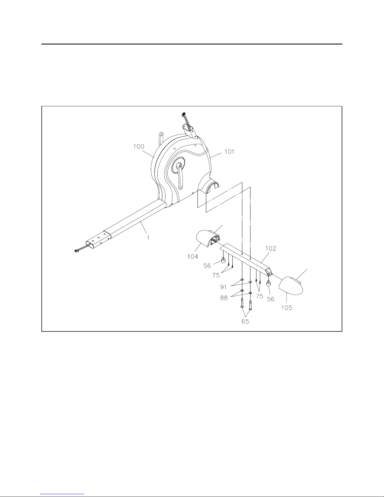
STEP 1
Attach the FRONT STABILIZER(102) to the FRONT FRAME(1) with BUTTON HEAD BOLTS
(M8x1.25x53mm)(65), LOCK WASHERS(M8)(88), and WASHERS(M8)(91).
STEP 2
Make the WHEELS(103) on the LEFT and RIGHT FOOT CAPS(104, 105) face the front. Slide the LEFT
and RIGHT FOOT CAPS(104, 105) onto both ends of the FRONT STABILIZER(102) so they fit over the
edges of the LEFT and RIGHT COVERS(100, 101) and secure with ROUND HEAD SCREWS
(M4x0.7x15mm)(75). Screw the FOOT ST ANDS(56) all the way up into the FRONT STABILIZER(102) on
both sides.
Place all parts from the box in a cleared area and position them on the floor in front of you. Remove all
packing materi als from your area a nd pla ce the m ba ck into the box. Do not dispose of the pa cking materi als
until a ssembly is completed. Read e a ch step carefully before beginning. If you are missing a part please call
our toll-free number for a ssistance 1-800-375-7520 or e-mail us at customerservice@sta min a products.com.
Wheel(103)
Wheel(103)
ASSEMBLY INSTRUCTIONS
8
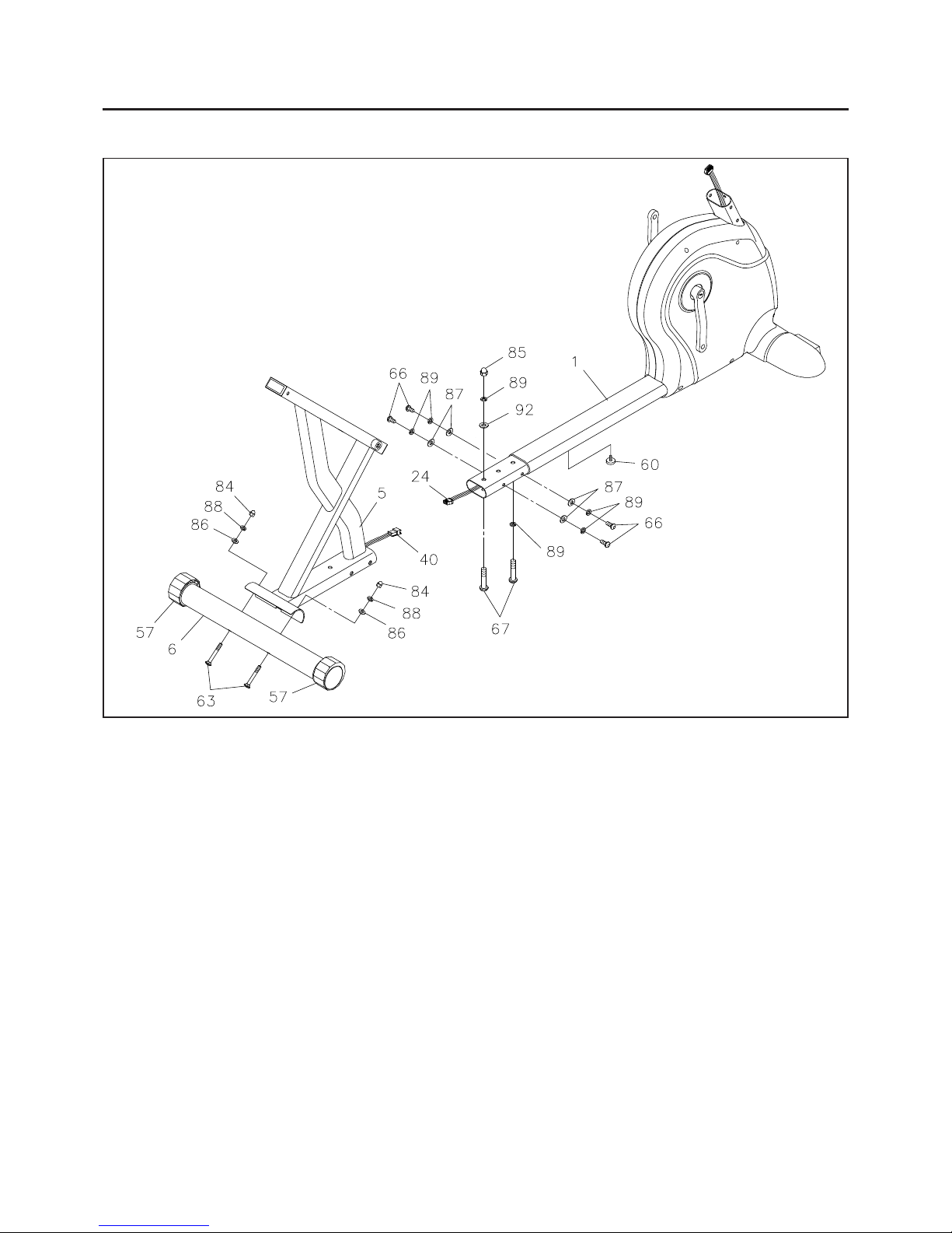
STEP 3
Attach the REAR ST ABILIZER(6) to the REAR FRAME(5) with CARRIAGE BOL TS(M8x1.25x75mm)(63),
ARC WASHERS(M8)(86), LOCK W ASHERS(M8)(88), and ACOR N NUTS(M8x1.25)(84).
STEP 4
Screw the STAND(60) all the way up into the bottom of the FRONT FRAME(1). Connect the PULSE
EXTENSION WIRE(40) to the CONTROL WIRE(24). Insert the REAR FRAME(5) onto the FRONT FRAME(1)
and se cure with BUTTON HEAD BOL TS(M10x1.5x20mm)(66), BUTTON HEAD BOL TS(M10x1.5x53mm)
(67), ARC WASHERS(M10)(87), LOCK WASHERS(M10)(89), WASHER(M10)(92), and ACORN NUT
(M10x1.5)(85).
NOTE: See page 13 for detailed leveling instructions to prevent rocking.
 Loading...