

Page 1
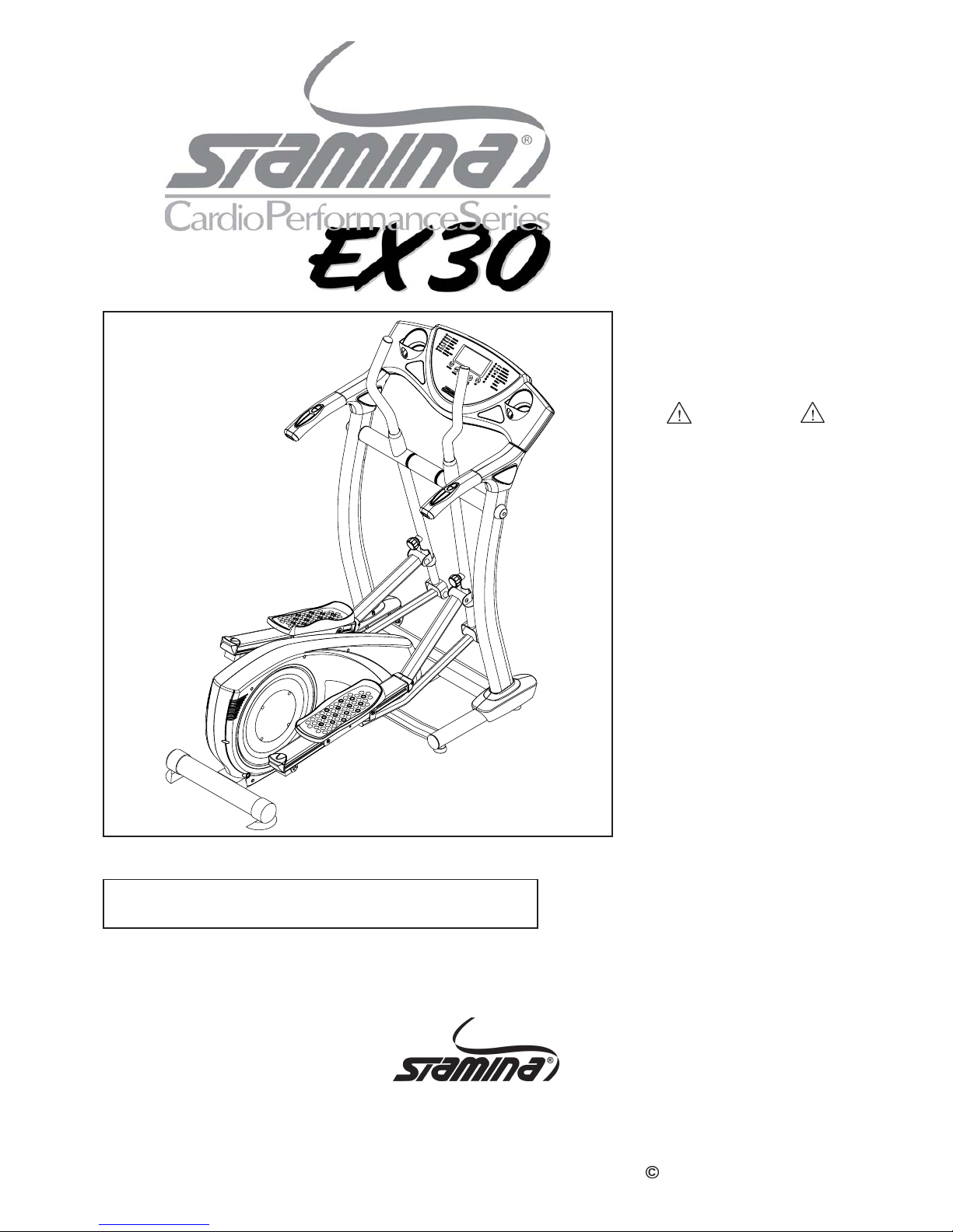
55-1900
STAMINA PRODUCTS
MADE IN TAIWAN
Product May Vary Slightly
From Pictured.
2006, 10
Exercise can present a health
risk. Consult a physician
before beginning any exercise
program with this equipment.
If you feel faint or dizzy,
immediately discontinue use
of this equipment. Serious
bodily injury can occur if this
equipment is not assembled
and used correctly. Serious
bodily injury can also occur if
all instructions are not
followed. Keep others and
pets away from equipment
when in use. Always make
sure all bolts and nuts are
tightened prior to each use.
Follow all safety instructions in
this manual.
When calling for parts or
service, please specify the
following number.
WA RNING
CAUTION:
Weight on this product should not exceed 250 lbs.
2040 N. Alliance, Springfield, MO 65803
Customer Service Number
1 (800) 375-7520
www.staminaproducts.com
This Product is Produced Exclusively by
2006 Stamina Products, Inc.
Owner's
Manual
Page 2

TABLE OF CONTENTS
Before starting any exercise or conditioning program you should consult with your personal
physicia n to see if you require a complete physical exa m. This is e specially i mporta nt if you
are over the age of 35, have never exercised before, are pregnant, or suffer from any
illness. READ AND FOLLOW THE SAFETY PRECAUTIONS. FAILURE TO FOLLOW
THESE INSTRUCTIONS CAN RESUL T IN SERIOUS BODILY INJURY.
WARNING:
2
SAFETY INSTRUCTIONS
Safety Instructions 2
Before Y ou Begin 4
Hardware Identification Chart 5
Assembly Instructions 6
Set Up Instructions 12
Operational Instructions 13
Exercise Workout 13
Computer Instructions 14
Storage 23
Maintenance 23
Conditioning Guidelines 24
Warm-up a nd Cool-Down 25
Product Parts Drawing 26
Parts List 27
Warranty 30
Fax/Mail Ordering Form 31
Page Page
WARNING:
Read all warnings posted on the EX
3.0.
Read this Owner's Manual and follow it carefully before using the EX
3.0. Make sure that it is
properly assembled and tightened before use.
We recommend that two people be available for assembly of this product.
Keep children away from the EX
3.0. Do not allow children to use or play on the EX 3.0. Keep
children and pets away from the EX
3.0 when it is in use.
It is recommended that you place this exercise equipment on an equipment mat.
Set up and operate the EX
3.0 on a solid level surface. Do not position the EX 3.0 on loose rugs or
uneven surfaces.
Inspect the EX
3.0 for worn or loose components prior to use.
Tighten/replace any loose or worn components prior to using the EX
3.0.
Before exercising, securely tighten both Adjustment Knobs(58) which secure the T ele scoping Bars(56).
Consult a physician prior to commencing an exercise program. If, at any time during exercise, you
feel faint, dizzy, or experience pain, stop and consult your physician.
Follow your physician's recommendations in developing your own personal fitness program.
Always choose the workout which best fits your physical strength and flexibility level. Know your
limits and train within them. Always use common sense when exercising.
Consult a physician before using the Pulse Recovery Function described on pages 15 and 16.
Do not wear loose or dangling clothing while using the EX
3.0.
Never exercise in bare feet or socks; always wear correct footwear, such as running, walking, or
crosstraining shoes. Be sure that they fit well, provide foot support a nd feature non-s kid rubber soles.
Be careful to maintain your balance while using, mounting, dismounting, or assembling the EX
3.0,
loss of balance may result in a fall and serious bodily injury.
Keep both feet firmly and securely on the Foot Pedals while exercising.
The EX
3.0 should not be used by persons weighing over 250 pounds.
The EX
3.0 should be used by only one person at a time.
The EX
3.0 is for consumer use only. It is not for use in public or semipublic facilities.
1.
2.
3.
4.
5.
6.
7.
8.
9.
10.
11.
12.
13.
14.
15.
16.
17.
18.
19.
20.
To reduce the risk of serious injury, read the following Safety Instructions before
using the STAMINA CPS EX
3.0 Elliptical.
Page 3

THANK YOU FOR PURCHASING THE
STAMINA CPS EX 3.0 Elliptical
To help you get started, we have pre-assembled most of your
STAMINA CPS EX 3.0 Elliptical at the factory with the exception
of those few parts left unassembled for shipping purposes.
Simply follow the few assembly instructions set forth in this manual. With
regular workouts you will be getting your body into sha pe and on your
way to achieving a happier and healthier lifestyle.
CALL US FIRST
3
Should you have any que stions,
please call our Customer Service Department toll-free number,
1 (800) 375-7520
Monday - Thursday, 7:30 A.M. - 5:00 P.M. Central Time.
Friday, 8:00 A.M. - 3:00 P.M., Central Time.
TELEPHONE
CUSTOMER SERVICE
Tel: 1 (800) 375-7520
FAX
CUSTOMER SERVICE
Fax: (417) 889-8064
MAIL
STAMINA PRODUCTS, INC.
ATTN: Customer Service
P.O. Box 1071
Springfield, MO. 65801-1071
ONLINE
CUSTOMER SERVICE
parts@staminaproducts.com
www.staminaproducts.com
Page 4
BEFORE YOU BEGIN
Thank you f or choosing the EX 3.0. We ta ke great
pride in producing this quality product and hope it
will provide many hours of quality exercise to make
you feel better, look better a nd enjoy life to its fullest.
Yes, it's a proven fact that a regular exercise
program can improve your physical and mental
health. Too often, our busy lifestyles limit our time
and opportunity to exercise. The EX 3.0 provides a
convenient and simple method to begin your assault
on getting your body in shape a nd a chieving a happier
and healthier lifestyle.
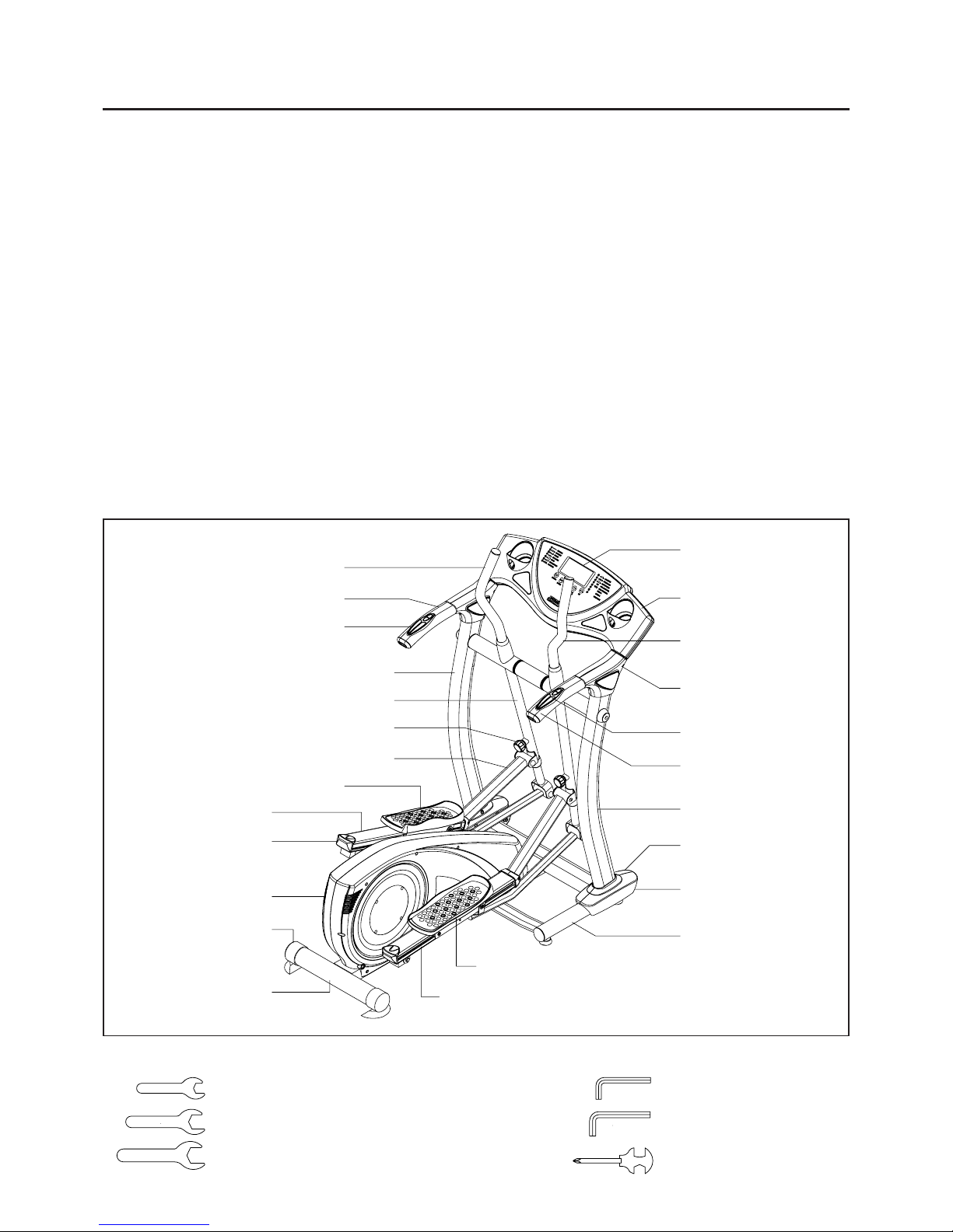
Before reading further, please review the drawing
below and familiarize yourself with the parts that are
labeled.
Read this manual carefully before using the
EX 3.0.
Right Handlebar
Right Side
Handrail Cover
Computer
Right Pedal Ca p
Pedal Rail
Left Pedal Cap
Main Fra me
Endcap
Right Upright
Heart Rate Sensor
Plate/T ension Down
Left Handlebar
Right Handrail
Right-Right Ba se
Cover
Left Cover
4
THE FOLLOWING TOOLS ARE INCLUDED FOR ASSEMBLY :
Wrench (10mm)
Wrench (13mm)
Wrench (17mm)
Left Upright
Left Pivoting Arm
Pedal Rail
Console Cover
Rail Ca p
Allen Wrench (5mm)
Allen Wrench (6mm)
Combination Wrench
Although Sta min a con structs its products with the
finest materials and uses the highest standards of
manufacturing and quality control, there can
sometimes be missing parts or incorrectly sized
parts. If you any questions or proble ms with the parts
included with your Elliptical EX 3.0, please do not
return the product. Contact us FIRST!
If a part is missing or defective, please call us toll
free at 1-800-375-7520 (in the U.S.). Our Customer
Service Staff is available to a ssist you from 7:30 A.M.
to 5:00 P .M. (Central T ime) Monday through Thursday
and 8:00 A.M. to 3:00 P.M. (Central T i me) on Friday.
If you would like to contact us on-line, go to our
website at www .stamin aproducts.com a nd a ccess the
Customer Service section.
Be sure to have the name and model number of
the product available when you contact us.
Front Base
Left-Right Ba se
Cover
Left Handrail
Adjustment Knob
Support Arm
Heart Rate Sensor
Plate/Tension Up
Page 5
5
Part No. and Description Qty
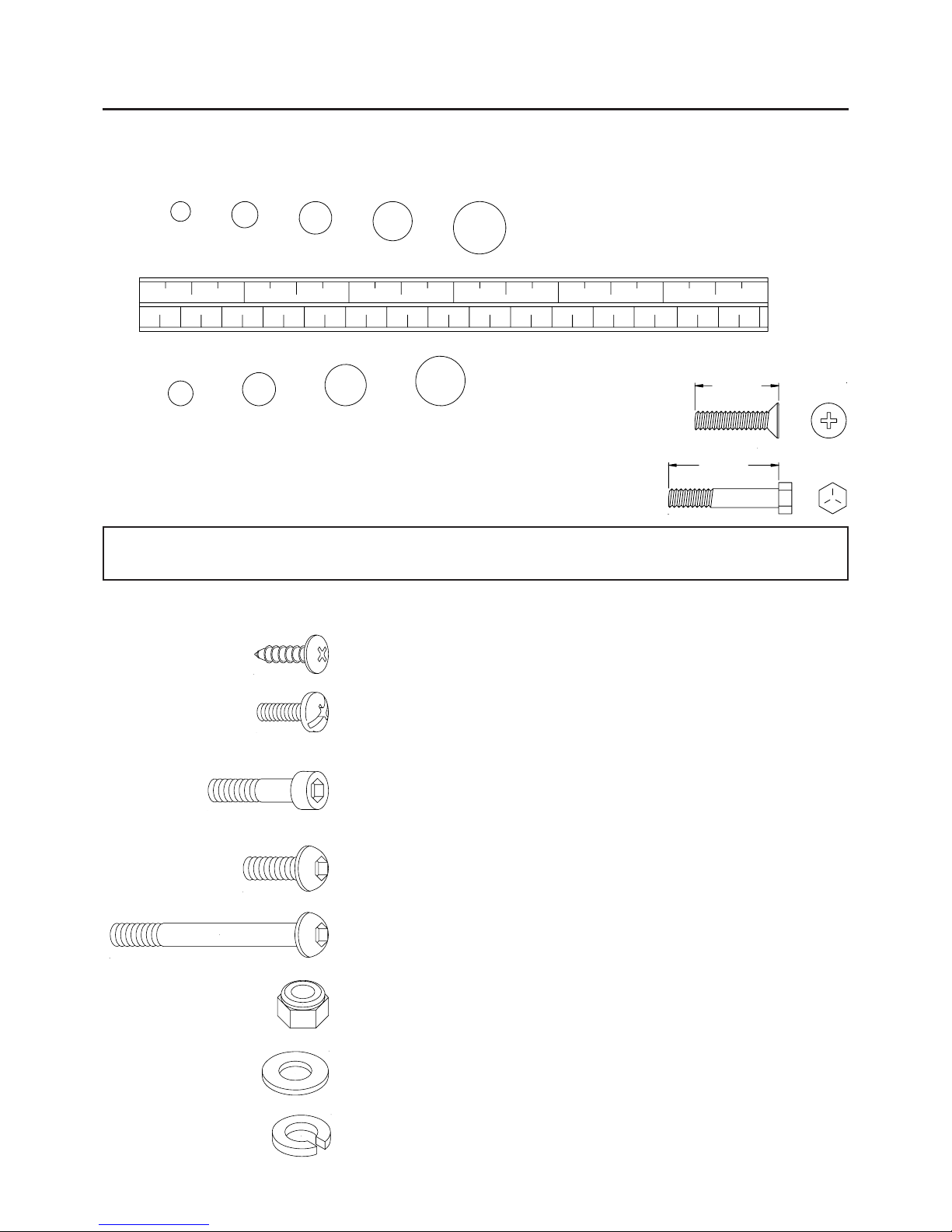
HARDWARE IDENTIFICATION CHART
This chart is provided to help identify the hardware used in the assembly process. Place the washers, the
end of the bolts, or screws on the circles to check for the corre ct diameter. Use the small scale to check the
length of the bolts and screws.
NOTICE: The length of all bolts and screws except those with flat hea ds is
measured from below the head to the end of the bolt or screw.
Flat head bolts and screws are measured from the top of the
head to the end of the bolt or screw.
mm.
in.
INCHES
MILLIMETERS
11/2021/2 31/2 41/2 51/2 61/2
0 10 20 30 40 50 60 70 80 90 100 110 120 130 140 150
6 8 10 12
3/16" 5/16" 1/2"3/8"1/4"
length
length
After unpacking the unit, open the hardware bag and make sure that you have all the following items.
Some hardware may be already attached to the part.
101 Bolt, Socket Head (M6 x 1 x 35mm) 4
102 Bolt, Socket Head (M8 x 1.25 x 16mm) 4
103 Bolt, Socket Head (M8 x 1.25 x 25mm) 2
104 Bolt, Socket Head (M8 x 1.25 x 40mm) 4
109 Bolt, Button Head (M8 x 1.25 x 90mm) 4
110 Bolt, Button Head (M10 x 1.25 x 85mm) 2
106 Bolt, Button Head (M8 x 1.25 x 16mm) 4
108 Bolt, Button Head (M8 x 1.25 x 30mm) 2
113 Nylock Nut (M6 x 1) 4
114 Nylock Nut (M8 x 1.25 x 8mm thick) 10
116 Nylock Nut (M10 x 1.25) 2
55 Large Washer 2
118 Washer (M10) 2
119 Lock W asher (M8) 12
94 Screw , Round Head (M4 x 20mm) 4
95 Screw , Round Head (M5 x 20mm) 2
96 Screw , Round Head (M5x 0.8 x 20mm) 2
98 Bolt, Round Head (M8 x 1.25 x 16mm) 4
Page 6
Place all parts from the box in a cleared area and position them on the floor in front of you. Remove all
packing materi als from your area a nd pla ce them ba ck into the box. Do not dispose of the pa cking materials
until assembly is completed. Read each step carefully before beginning. If you are missing a part please
call our toll-free number for assistance 1 (800) 375-7520 or e-mail us at:
parts@staminaproducts.com
6
ASSEMBLY INSTRUCTIONS
NOTE: You will need to obtain assistance from another person for the following assembly.
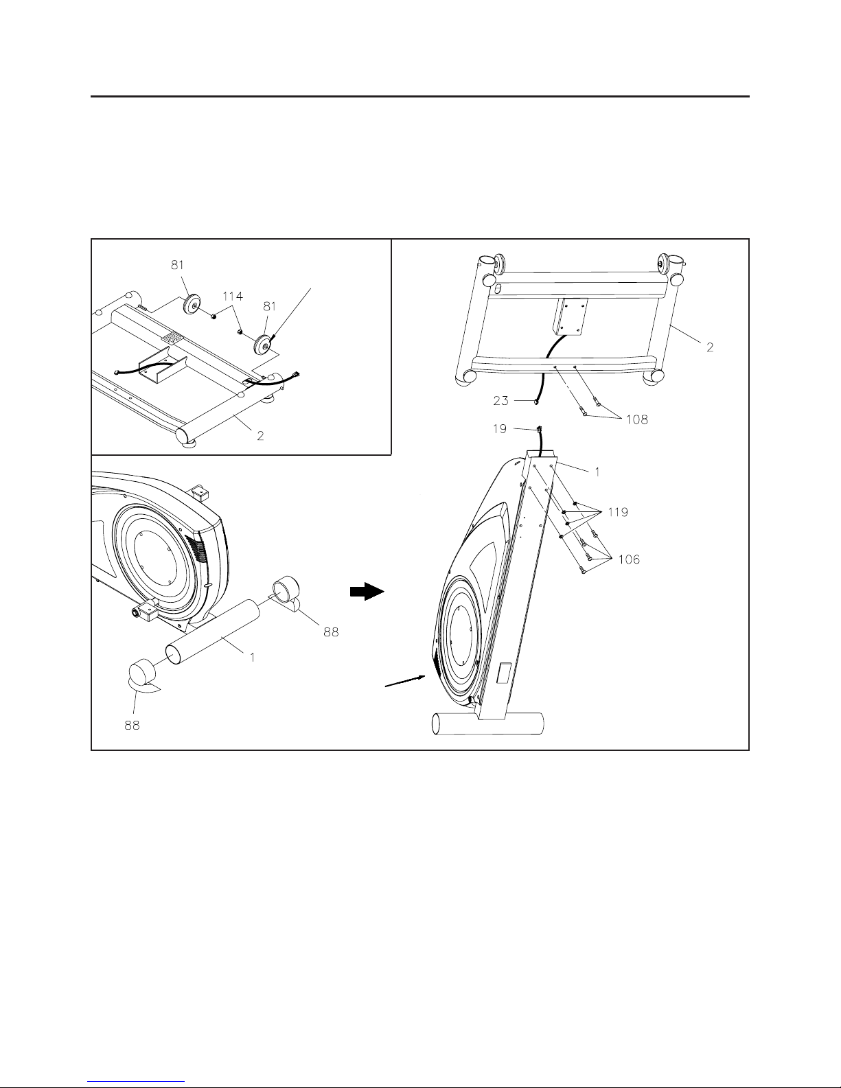
A.
STEP 1
Refer to inset drawing A. Place the side of the WHEELS(81) with the longer shoulder toward the frame of
the FRONT BASE(2). Then atta ch the WHEELS(81) onto the threaded inserts of the FRONT BASE(2) with
NYLOCK NUTS(1 14).
Put a rug or some other protective
material under this corner of the
Plastic Covers to avoid damaging
the Plastic Covers.
Place the side of the WHEEL(81)
with longer shoulder toward the
side frame of the FRONT
BASE(2).
STEP 2
Remove the ENDCAPS(88) from the STABILIZER of the MAIN FRAME(1). One person should tilt the unit
up and hold it in position as shown above while the other person connects the BASE CONNECTION WIRE
(23) to the LOWER CONNECTION WIRE(19), and then inserts the BASE FRAME(2) into the MAIN
FRAME(1) and secures it with BUTT ON HEAD BOLTS(M8x1.25x16mm)(106) and LOCK W ASHERS(M8)
(119). Attach the crossing bar on the FRONT BASE(2) to the MAIN FRAME(1) with BUTTON HEAD
BOLTS(M8x1.25x30mm)(108).
Lay the unit down and press the ENDCAPS(88) back on the STABILIZER of the MAIN FRAME(1).
(No washers are used
here with bolts 108.)
Page 7
ASSEMBLY INSTRUCTIONS
7
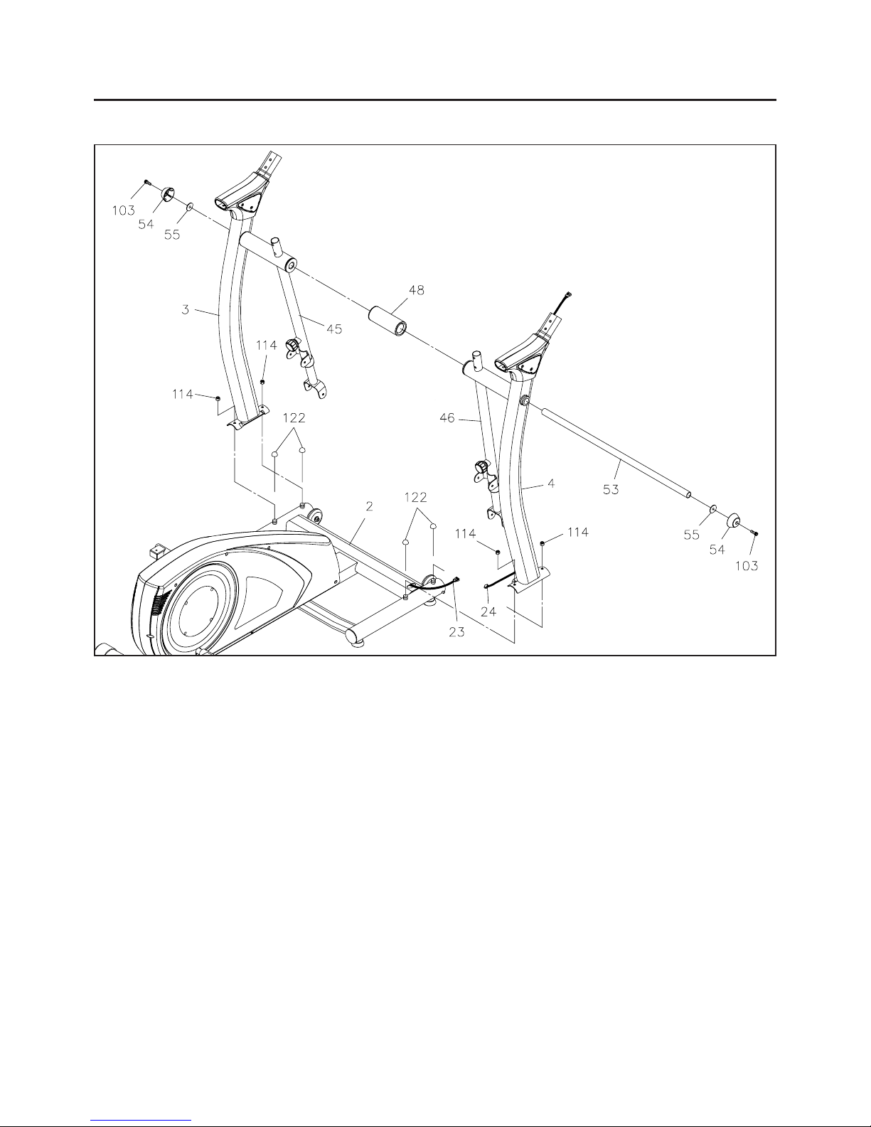
STEP 3
Connect the UPPER CONNECTION WIRE(24) in the RIGHT UPRIGHT(4) to the BASE CONNECTION
WIRE(23), then attach the RIGHT UPRIGHT(4) to the FRONT BASE(2) with the NYLOCK NUTS(M8x1.25)
(114). Do not tighten the nuts until STEP 8.
STEP 4
Attach the LEFT UPRIGHT(3) to the FRONT BASE(2) with the NYLOCK NUTS(M8x1.25)(114). Do not
tighten the nuts until STEP 8.
STEP 5
Refer to the illustration. Insert the LONG SHAFT(53) through the hole in the RIGHT UPRIGHT(4), RIGHT
PIVOTING ARM(46), SP ACER TUBE(48), LEFT PIVOTING ARM(45) and LEFT UPRIGHT(3), then secure
with LARGE W ASHERS(55), SECURING CAPS(54), and SOCKET HEAD BOL TS(M8x1.25x25mm)(103)
on both sides. Do not tighten the bolts until STEP 8.
For shipping purposes, the NUT CAPS(122) a nd NYLOCK NUTS(M8x1.25)(1 14) are attached on
the FRONT BASE(2). Remove the NUT CAPS(122) from the FRONT BASE(2) a nd keep them for
Assembly STEP 12. Remove the NYLOCK NUTS(M8x1.25)(1 14) f or the f ollowing assembly.
NOTE:
Keep the NUT CAPS(122)
for Asse mbly STEP 12.
Page 8
8
ASSEMBLY INSTRUCTIONS
Connection Wire from
the COMPUTER(25)
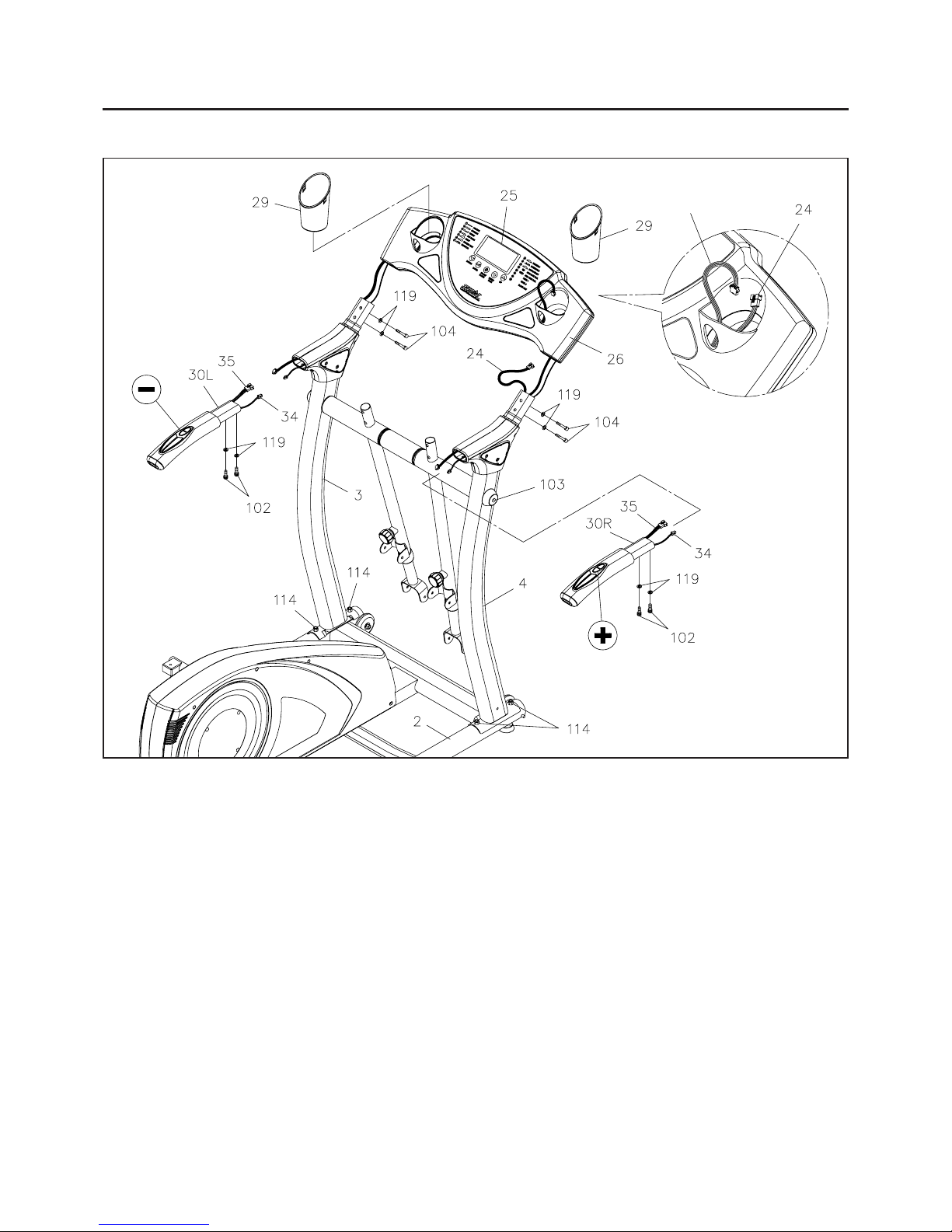
STEP 6: To install the CONSOLE ASSEMBLY(26,27,28), run the two Connection Wires at each side of
the CONSOLE ASSEMBL Y(26,27,28) through the LEFT a nd RIGHT UPRIGHTS(3, 4). And run the UPPER
CONNECTION WIRE(24) go into the CONSOLE ASSEMBL Y(26,27,28). Insert the CONSOLE ASSEMBLY
(26,27,28) onto the LEFT and RIGHT UPRIGHTS(3, 4) and secure with SOCKET HEAD BOLTS
(M8x1.25x40mm)(104) and LOCK WASHERS(M8)(119).
STEP 7: Refer to the inset drawing. Connect the UPPER CONNECTION WIRE(24) to the Connection
Wires from the COMPUTER(25). Arra nge the wire s for cle arness, then pre ss the BOTTLE HOLDERS(29)
into the CONSOLE ASSEMBL Y(26,27,28) at the position as shown in the illustration.
STEP 8: Tighten the SOCKET HEAD BOLTS(M8x1.25x25mm)(103) at both sides of the UPRIGHTS
(3, 4). Tighten the NYLOCK NUTS(M8x1.25)(1 14) at both sides of the FRONT BASE(2).
STEP 9: There is a " - " mark on the LEFT HANDRAIL(30L), and a " + " mark on the RIGHT HANDRAIL
(30R). Connect the PULSE SENSOR WIRE(35) and CONNECTION WIRE(34) in the RIGHT HANDRAIL
(30R) to the connection wires from the COMPUTER(25). Insert the RIGHT HANDRAIL(30R) into the
RIGHT UPRIGHT(4) and secure with SOCKET HEAD BOL TS(M8x1.25x16mm)(102) a nd LOCK W ASHER
(M8)(119). Repeat on the left side.
Page 9
9
ASSEMBLY INSTRUCTIONS
L
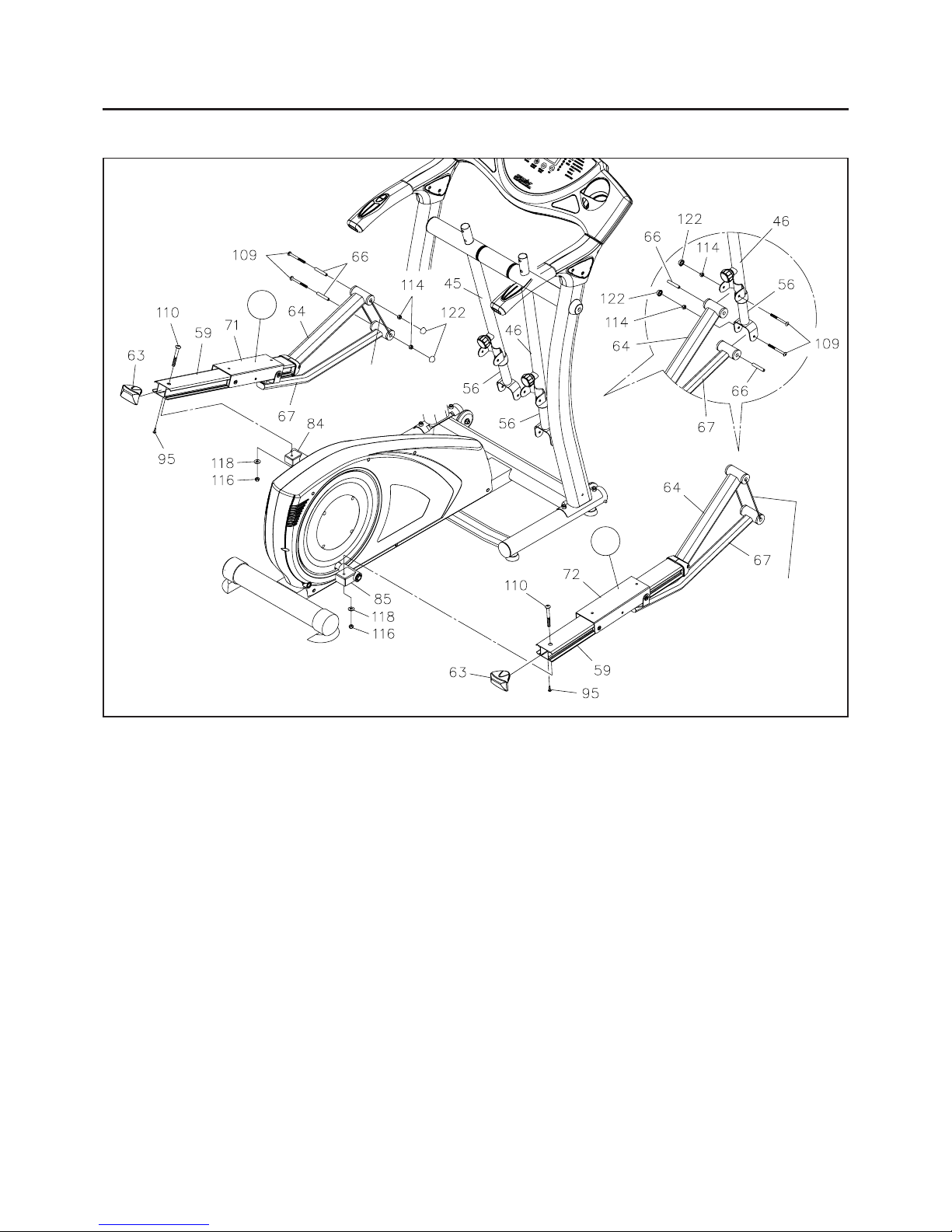
STEP 12: Refer to the inset drawing. Insert the SHAFT SLEEVE(66) into the SUPPORT ARM(64).
Attach the SUPPORT ARM(64) at right side to RIGHT PIVOTING ARM(46) with BUTTON HEAD BOLT
(M8x1.25x90mm)(109) and NYLOCK NUT(M8x1.25)(114). Insert the SHAFT SLEEVE(66) into the
LINKAGE(67). Attach LINKAGE(67) at right side to TELESCOPING BAR(56) in the RIGHT PIVOTING
ARM(46) with BUTTON HEAD BOL T(M8x1.25x90mm)(109) a nd NYLOCK NUT(M8x1.25)(1 14). Press a
NUT CAP(122) onto each NYLOCK NUT(M8x1.25)(1 14). Repeat on the left side.
R
Do not cut off the
tie until STEP 12.
Install the right PEDAL RAIL ASSEMBLY by attaching the PEDAL RAIL(59) to the RIGHT RAIL
CONNECTOR(85) with BUTTON HEAD BOL T(M10x1.25x85mm)(1 10), W ASHER(M10)(118), a nd NYLOCK
NUT(M10x1.25)(116). Repe at on the left side.
NOTE: The RAIL CONNECTORS(84, 85) must face toward the back as shown in the illustration above.
STEP 10
NOTE: An "L" decal identifies the LEFT PEDAL SLIDER(71) and an "R" decal identifies the RIGHT
PEDAL SLIDER(72).
The RIGHT PEDAL SLIDER(72) is attached to the right PEDAL RAIL ASSEMBL Y. Attach the right PEDAL
RAIL ASSEMBL Y to the right side of the elli ptical unit. Attach the LEFT PEDAL SLIDER(71) a nd PEDAL
RAIL ASSEMBLY to the left side of the elliptical unit in the same manner.
STEP 1 1: Press the RAIL CAPS(63) into the PEDAL RAILS(59) a nd secure with ROUND HEAD SCREWS
(M5x20mm)(95).
Do not cut off the
tie until STEP 12.
Page 10
ASSEMBLY INSTRUCTIONS
L
R
10
L
R
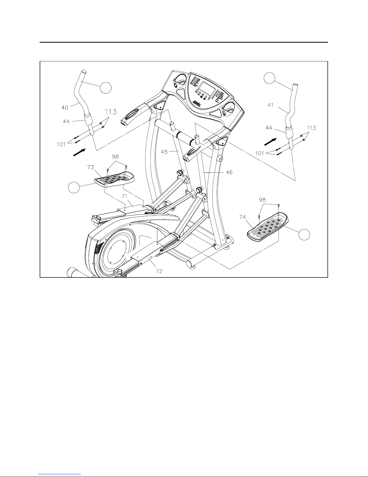
STEP 13
There is an "L" decal on the LEFT PEDAL CAP(73), and an "R" decal on the RIGHT PEDAL CAP(74).
Attach the RIGHT PEDAL CAP(74) to the RIGHT PEDAL SLIDER(72) with ROUND HEAD BOLTS
(M8x1.25x16mm)(98). Repeat on the left side.
CAUTION:
The lip on the PEDAL CAPS(73, 74) must face inside. The sides without a li p face outside as
shown.
Assemble the SOCKET HEAD BOL TS(M6x1x35mm)(101) f ollowing the direction a s shown by the
arrows. The Bolt Heads must go through the holes on the PIVOTING ARMS(45, 46) to attach the
HANDLEBARS(40, 41).
STEP 14
There is a "L" decal on the LEFT HANDLEBAR(40), and a "R" decal on the RIGHT HANDLEBAR(41).
Slide a HANDLEBAR SLEEVE(44) onto the RIGHT HANDLEBAR(41). Insert the RIGHT HANDLEBAR(41)
into the RIGHT PIVOTING ARM(46 ) and secure with SOCKET HEAD BOLTS(M6x1x35mm)(101) an d
NYLOCK NUTS(M6x1)(113). Slide the HANDLEBAR SLEEVE(44) down to cover the bolts on the RIGHT
HANDLEBAR(41). Repeat on the left side.
NOTE:
Page 11

ASSEMBLY INSTRUCTIONS
11
STEP 15: There is an "L-L" decal on the LEFT-LEFT BASE COVER(77), and an "R-L" decal on the
RIGHT-LEFT BASE COVER(78). Attach the LEFT-LEFT and RIGHT-LEFT BASE COVERS(77, 78) to the
LEFT UPRIGHT(3).
There is an "L-R" decal on the LEFT-RIGHT BASE COVER(79), and a n "R-R" de cal on the RIGHT-RIGHT
BASE COVER(80). Attach the LEFT-RIGHTand RIGHT-RIGHT BASE COVERS(79, 80) to the RIGHT
UPRIGHT(4).
L-R
R-R
L-L
R-L
To assemble the RIGHT BASE COVERS(79, 80), place the LEFT-RIGHT BASE COVER(79) at the inner
side of the RIGHT UPRIGHT(4). Place the RIGHT-RIGHT BASE COVER (80) at the outer side of the
RIGHT UPRIGHT(4) and bolt the covers together with the ROUND HEAD SCREWS(M4x20mm)(94). Then
bolt the LEFT-RIGHT BASE COVER(79) to the RIGHT UPRIGHT(4) with ROUND HEAD SCREW
(M5x0.8x20mm)(96). Repeat on the left side.
STEP 16: Atta ch the RIGHT CHROMED PLA TES(39) to the RIGHT SIDE HAND RAIL COVERS(38) with
the hooks on the chromed plates. Be careful not to da mage the hooks when atta ching the RIGHT CHROMED
PLA TES(39). Repeat to atta ch the LEFT CHROMED PLA TES(37) to the LEFT SIDE HANDRAIL COVERS
(36).
STEP 17: Connect the ADAPTER(121) to the connector located on the back right end of the RIGHT
COVER(8). Plug the ADAPTER(121) into an electrical outlet.
Page 12

SET UP INSTRUCTIONS
LEVELING:
MOVING:
Equipment Mat
Place the EX 3.0 in the area where it will be used. It is recommended that the EX 3.0 be placed on an
equipment mat. The maxi mum usage dimen sions of EX 3.0 are approximately 62 5/8" long x 32 3/4" wide x
58 3/8" tall. (These dimensions may vary up to one inch.) An area 4 feet wide x 7 feet long is required for
safe operation of the EX 3.0. Ma ke sure that adequate spa ce is available f or a ccess to a nd pa ssage around
the EX 3.0.
Adjust the LEVELING STANDS(82) under the FRONT BASE(2) so that the EX 3.0 sits on the
floor without rocking. Refer to the instructions below the illustration.
Grasp the HANDRAILS and the shaft of the PIVOTING ARMS to lift and move the EX 3.0.
Two people are required.
12
Loosen the NUTS(M8x1.25)(117) until they
touch the LEVELING STANDS(82). Adjust the
LEVELING STANDS(82) for leveling. Tighten
the NUTS(M8x1.25)(117) securely against the
FRONT BASE(2) to lock the stand in position.
Grasp these parts
for moving
Grasp these parts
for moving
FUNCTION INSPECTION:
Visually inspect the EX 3.0 to verify that assembly is as shown in the above illustration. Check the function
of the EX 3.0. Stand on the f oot pedals and place your hands at a comfortable position on the handlebars.
Slowly move your highest foot forward and follow the natural path of the machine. Turn the crank slowly
through one complete revolution to verify that the drive train functions properly. Use the "ENTER" and
"
/ " buttons on the COMPUTER(25) to select a progra m a nd verify that the Magnetic Syste m provides
different tensions. Refer to the COMPUTER INSTRUCTIONS on pages 14 to 22.
Locate and read the WARNING LABEL(120) on the EX
3.0. Make sure that all users re a d the
WAR NING LABEL(120).
CAUTION:
Page 13

OPERATIONAL INSTRUCTIONS
ELLIPTICAL PATH ADJUSTMENT
The elliptical path of the PEDAL CAPS(73, 74) ca n be a djusted by moving the TELESCOPING BARS(56)
closer to or further from the PIVOTING ARMS(45, 46). Refer to the following illustrations.
To adjust, loosen and pull the ADJUSTMENT KNOB(58). Adjust the position of the TELESCOPING
BARS(56) to new position. Relea se the ADJUSTMENT K NOB(58) a nd ma ke sure the pin on the knob get
into the adjustment hole in the TELESCOPING BARS(56). T ighten the ADJUSTMENT KNOB(58).
13
CAUTION:
EXERCISE WORKOUT
To start using the EX 3.0, stand on the foot pedals, grasp the handlebars, move your highest foot forward
and follow the natural path of the machine.
CAUTION: Do not use handlebars for upper body strength training.
Start at a load level that is comfortable to familiarize yourself with the machine. Once you are comfortable
start adjusting the load level to achieve the workout desired.
Load Level Adjustment
The load level of EX 3.0 ca n be cha nged at a ny ti me during your workout. Adjusting the loa d level will allow
you to increase or decrease your intensity level.
Forward and Reverse
The EX 3.0 ca n be used in the forward a nd reverse direction to vary the muscle s that you work out. This will
also vary your workout helping you to stay motivated. To change directions, simply slow the pedals down
until they stop and switch directions.
LONG STRIDE POSITION
( Large Elliptical Path )
SHORT STRIDEPOSITION
( Small Elliptical Path )
MEDIUM STRIDEPOSITION
( Middle Elliptical Path )
Always adjust the TELESCOPING BARS(56) to the same position at both sides. Securely
tighten both LOCKING KNOBS(58) before exercising.
Page 14

COMPUTER INSTRUCTIONS
14
BUTTONS:
Press to select a progra m, P1 through P15. Pre ss the ENTER button to select the value s of
the various settings.
Press to select the function value displays of RPM, KJOULE, and WATT, or SPEED,
CALORIES, and TARGET HEART RATE.
ENTER:
Press to start the selected progra m. Press the START
/ PAUSE button to pause the progra m.
You can press the START / PAUSE button again to continue to run the current program, or
use " / " buttons to select a new program.
Press and hold the button down for two seconds to reset all of the function values to zero.
(Except WATT and TARGET HEART RATE).
START /
P AUSE :
/ UP : Press to select programs P1 through P15. Press to increase the values of the settings.
Press to increase the WATT of workload level when running a program.
Your EX
3.0 utilizes a magnetic braking system to create resistance for your workout. You control the
a mount and pattern of this resista nce by mea ns of the a dvanced computer console mounted at the center of
the handrail. We recommend that you use this computer console to vary your workout from session to
session and note your progress toward your fitness goals. When used regularly in this way, the computer
console can become a n importa nt source of motivation a nd interest which will help keep you on tra ck toward
achieving your fitness goals.
Press to select programs P1 through P15. Press to decrease the values of the settings.
Press to decrease the WATT of workload level when running a program.
/ DOWN :
HEART RA TE RECOVERY: Press to activate
the HEART RATE RECOVERY function after training.
ATTENTION: For protecting the magnetic braking system, if the pedaling speed is lower
than 20 RPM during workout, the syste m will relea se the bra king resista nce automatically . It
is for helping you to speed up again. The re sistance will rea ch back to the preset workload
about 10 seconds after the RPM more than 20.
Page 15

COMPUTER INSTRUCTIONS
LCD DISPLAY INSTRUCTIONS
Indicates the program selected has started.
Indicates the program selected has stopped. You must be in STOP mode to setup the
programs.
Displays programs for selection during setup, from P1 to P15.
Displays the selected program during exercise.
If the program time is "0:00", displays flashing "0.0" for preseting the DISTANCE of
program during setup, from 1 to 999 mile.
Displays the distance during exercise, from zero to 999.9 miles.
Displays the percentage of body fat in Body Fat Progra m.
Displays the CALORIES burned, from zero to 9999 Kcal, or KJOULE, from 0 to 9999.
Press "ENTER" button to select the display of CAL or KJOULE.
NOTE: The calorie and Kjoule re adouts are an estimate for an average user. It should
be used only a s a comparison between workouts on this unit.
Displays the BMR in Body Fat Program. (BMR is Basal Metabolic Rate. See page 21.)
Displays flashing "0:00" f or preseting the progra m time during setup, from 1:00 to 99:00.
Displays the time during exercise, from 1 sec up to 99:59 minutes.
Displays HEIGHT for input when you sele ct the Body Fat Progra m, from 44 to 77 inches.
15
Indicates the gender (Male or Female) selected for the Body Fat Program.
Displays the current speed from zero to 99.9 mph, or RPM from 20 to 150 rpm.
NOTE: When the RPM is over 150 rpm, the computer will display an error message "E".
When the RPM is lower than 20 rpm, the computer will display an error message "E"
and release the braking resistance automatically for helping you to speed up again.
Press "ENTER" button to select the display of SPEED or RPM.
Displays WEIGHT for in put when you sele ct the Body Fat Program, from 23 to 440 lbs.
NOTE: Maximum body weight for user is 250 lbs.
Page 16

COMPUTER INSTRUCTIONS
16
Displays fla shing "35" for preseting the AGE for programs during setup, from 10 to 99.
Plea se note that although the computer allows input for ages beginning at 10 ye ars old,
this product is not recommended for use by children.
Displays the Heart Rate, from 40 to 240 beats per minute.
NOTE: You must place both of your hands on the Heart Rate Sensors on the ha ndrails
to input the pulse signal. Each pulse signal will be accompa nied with one "
" symbol
flash. If you do not place your hands correctly and eight (8) seconds passes without a
pulse input, the computer will turn off the pulse circuit. Place your hands back on the
Heart Rate Sensors correctly, the Heart Rate readout will a ppear again.
Displays the BODY TYPE in Body Fat Progra m. (See page 21 for Body T ype information.)
PROGRAM DESCRIPTIONS
This computer contains 15 different programmable workouts. You can preset your exercise time and the
computer will divide the time into 10 intervals. If you do not set the program time in advance, the computer
will use the preset value of 30 minutes. In this ca se, you ca n preset the DISTANCE for the progra m to count
down.
(P1) MANUAL
MANUAL PROGRAM: P1 is a ma nual program allowing the user to have
full manual control of the workload. Use the " " button to increase the
WATT of workload level. Use the " " button to decrease the WATT of
workload level.
PRESET PROGRAMS: P2 to P10 are preset automatic programs. The profiles are shown on the face of
the computer. Use the "
" button to increase the WATT of workload level of the program. Use the " "
button to decrease the WATT of workload level of the program.
(P2) ROLLING (P3) VALLEY
(P5) RAMP (P6) FITNESS TEST
(P4) FAT BURN
(P7) RANDOM
(P8) PLATEAU (P9) INTERVALS (P10) MOUNTAIN
Displays the Target Heart Rate of programs during exercise, or the WATT of workload
level, from 40 to 400 watt. Press "ENTER" button to select the display of Target Heart
Rate or WATT.
NOTE: The WATT readouts are the workload level of your current workout. You can
use " / " buttons to adjust the WA TT in any time during your workout.
Displays the BMI in Body Fat Progra m. (BMI is Body M ass Index. See page 21.)
Page 17

COMPUTER INSTRUCTIONS
HEART RATE CONTROL PROGRAMS: P11 and P12 are preset automatic heart rate control programs.
The maximum heart rate is based on your age. You must input your age and always hold the Heart Rate
Sensors on the Handrails with both hands when using the heart rate control programs.
( P11 ) 60% of Maximum Heart Rate
USER SETTING PROGRAMS: P13 a nd P14 are the automatic programs that allows the user to manually
preset ea ch of the 10 intervals. U nder STOP mode, use "
/ " and "ENTER" buttons to edit the progra m
profile. The program profile will be stored in the memory after setup. You can modify the profile anytime
under the STOP mode. NOTE: The changes can be stored only under STOP mode.
When running a program, you still can use the "
" button to increase the WATT of workload level of the
program. Use the "
" button to decrea se the WA TT of workload level of the program. But, these cha nges
will not be stored in memory.
17
NOTE:
Displays U1 for Program 13.
Displays U2 for Program 14.
U1
U2
PROGRAM 13 ( P13 ):
PROGRAM 14 ( P14 ):
( P12 ) 85% of Maximum Heart Rate
(P15) BODY FAT
BODY FAT PROGRAM: P15 is a special program designed to calculate
your body fat ratio and to suggest a specific preset program profile,
resistance level, and TARGET HEART RATE that are suitable for you to
burn body fat during your workout. See pages 20 - 21 for details.
Always try to keep your HEART RA TE re adout close to the T ARGET HEAR T
RATE during your workout. Use the " " button to increase the WA TT of
workload level of the progra m. Use the " " button to decrease the WA TT
of workload level of the program.
The program will monitor your pulse and adjust the
workload, or intensity, automatically to keep your pulse
within your Target Heart Rate Zone. This zone is plus or
minus five heart beats from your Target Heart Rate as
determined by your age and the progra m that you selected.
For example:
If your age is 30, your maximum heart rate is 190.
If you select P1 1, 60% of your maximum heart rate is 1 14.
To determine your Heart Rate Zone, subtract five from
114 for the minimum number in your zone, and add five
to 1 14 for the maximum number in your zone. Y our Target
Heart Rate Zone in this example is 109 to 119.
The program will monitor your pulse and adjust the
workload automatically to keep your pulse within the
Target Heart Rate Zone (109-119) during your workout.
Page 18

COMPUTER INSTRUCTIONS
18
NOTE:
Select the progra m that you desire and set the function value s to adjust your workout. The different categories
of programs operate in different ways but, the computer will guide you step by step to setup the program
easily. Refer to the following list to learn what you may change in the programs.
CATEGORY PROGRAM VARIABLES
Manual Program P1 Time, Distance
Preset Program P2 ~ P10 Time, Distance
Heart Rate Control Progra m P11 ~ P12 Time, Dista nce, Age
User Setting Progra m P13 ~ P14 Time, Distance, Age, 10 Intervals
Body Fat Progra m P15 Gender, Height, Weight, Age
Y ou may pre set TIME or DISTANCE for a program. If you preset a value f or TIME, the computer will
not allow you to set DISTANCE. If you keep TIME at "0:00", the computer will flash "0.0" allowing
you to input DISTANCE, use 30 minutes for the program time and time will count up from 0.
Workout Time (Except in Program 15)
Distance (Except in Program 15)
Heart Rate Control (Program 11 and 12)
Body Fat (Program 15)
A. MANUAL PROGRAM (P1)
STEP 2 : SELECT PROGRAM
The Manual Program (P1) is always displayed first when you turn on the computer. If necessary, press
" / " buttons to select the Manual Program.
STEP 1: POWER ON
Power comes on when you begin pedaling or when you press either ENTER or START
/ PAUSE button.
STEP 3: SET THE PROGRAM TIME OR DISTANCE, AND ADJUST WATT
Press the ENTER button, the TIME function mode will a ppear with the display fla shing "0:00". Use "
/ "
buttons to set the progra m time, from one minute up to 99 minutes with one minute incre ments. Or , you ca n
keep TIME as "0:00" and press the ENTER button to enter the mode to set the DISTANCE. Use " / "
buttons to set the DISTANCE, from one mile up to 999 miles with one mile increments. Press the ENTER
button to enter the mode to set the WATT of workload level. Use " / " buttons to set the WATT, from 40
to 400 with 10 watt increments. You will see the height of the program profile on the display are changed
with the change of the WATT .
STEP 4 : START TO WORKOUT
Now you are ready to begin exercising. The program will not start until you press the START / PAUSE button.
OPERA TION INSTRUCTIONS
The advanced computer with diversified programs allows you to control the following features:
Page 19

COMPUTER INSTRUCTIONS
B. PRESET PROGRAMS (P2 to P10)
STEP 1: POWER ON
Power comes on when you begin pedaling or when you press either ENTER or START / PAUSE button.
STEP 2 : SELECT PROGRAM
Press "
/ " buttons until the desired program is displayed.
STEP 3: SET THE PROGRAM TIME OR DISTANCE, AND ADJUST WATT
Press the ENTER button, the TIME function mode will a ppear with the display fla shing "0:00". Use "
/ "
buttons to set the progra m time, from one minute up to 99 minutes with one minute incre ments. Or , you ca n
keep TIME as "0:00" and press the ENTER button to enter the mode to set the DISTANCE. Use " / "
buttons to set the DISTANCE, from one mile up to 999 miles with one mile increments. Press the ENTER
button to enter the mode to set the WATT of workload level. Use " / " buttons to set the WATT with 10
watt increments. You will see the height of the program profile on the display are changed with the change
of the WATT.
STEP 4 : START TO WORKOUT
Now you are ready to begin exercising. The program will not start until you press the START
/ PAUSE button.
19
C. HEART RATE CONTROL PROGRAMS (P11 and P12)
STEP 2 : SELECT PROGRAM
Press " / " buttons until the desired program is displayed.
STEP 3: SET THE PROGRAM TIME OR DIST ANCE, AND AGE
Press the ENTER button, the TIME function mode will a ppear with the display fla shing "0:00". Use "
/ "
buttons to set the progra m time, from one minute up to 99 minutes with one minute incre ments. Or , you ca n
keep TIME as "0:00" and press the ENTER button to enter the mode to set the DISTANCE. Use " / "
buttons to set the DISTANCE, from one mile up to 999 miles with one mile increments.
Press the ENTER button to enter the mode to set the AGE. Use " / " buttons to set the AGE, from 10
up to 99 years old. Plea se note that although the computer allows input f or ages beginning at 10 years old,
this product is not recommended for use by children.
STEP 4 : START TO WORKOUT
Press the START
/ PAUSE button to start to workout. Always hold the Heart Rate Sensors on the Ha ndrails
with both hands.
STEP 1: POWER ON
Power comes on when you begin pedaling or when you press either ENTER or START
/ PAUSE button.
NOTE: Depend on the profile of the Program, you can reduce the workload of the first interval of the 10
intervals program profile down to 40 watt. And you just can increase the highest interval of the
program profile up to 400 watt.
Page 20

COMPUTER INSTRUCTIONS
D. USER SETTING PROGRAMS (P13 and P14)
STEP 1: POWER ON
Power comes on when you begin pedaling or when you press either ENTER or START / PAUSE button.
STEP 2 : SELECT PROGRAM
Press "
/ " buttons until the desired program is displayed.
STEP 3: SET THE PROGRAM TIME OR DIST ANCE, AND AGE
Press the ENTER button, the TIME function mode will a ppear with the display fla shing "0:00". Use "
/ "
buttons to set the program time, from 5 minutes up to 99 minutes with one minute incre ments. Or, you can
keep TIME as "0:00" and press the ENTER button to enter the mode to set the DISTANCE. Use " / "
buttons to set the DISTANCE, from one mile up to 999 miles with one mile increments.
Press the ENTER button to enter the mode to set the AGE. Use " / " buttons to set the AGE, from 10
up to 99 years old. Plea se note that although the computer allows input f or ages beginning at 10 years old,
this product is not recommended for use by children.
NOTE: With the input of age, the computer will display a T AR GET HEART RA TE when running the program.
The TARGET HEART RATE is 85% of your Maximum Heart Rate, and your Maximum Heart Rate
is (220 - AGE). If your pulse is equal to or greater than the TARGET HEART RA TE during workout,
the value of HEART RA TE will kee p fla shing. Please note that this is a warning for you to slow
down or lower the WATT of workload level.
STEP 4 : EDIT THE PROGRAM PROFILE
Press the ENTER button, interval 1 will begin flashing. Use "
/ " buttons to set the load for interval 1.
Press the ENTER button to proceed to the next interval. Use " / " buttons to set the load for e a ch interval.
STEP 5 : START TO WORKOUT
Now you are ready to begin exercising. The program will not start until you press the START
/ PAUSE button.
E. BODY FAT PROGRAM (P15)
STEP 1: POWER ON
Power comes on when you begin pedaling or when you press either ENTER or START / PAUSE button.
STEP 2 : SELECT PROGRAM
Press "
/ " buttons until PROGRAM 15 is displayed.
STEP 3: SELECT GENDER AND INPUT YOUR HEIGHT, WEIGHT, AND AGE
Press the ENTER button, the GENDER mode will appear with the display flashing "
". Use " / "
buttons to display the correct gender. Press the ENTER button and use "
/ " buttons to set the values
of your HEIGHT , WEIGHT , and AGE. After you input your age and press the ENTER button, the "PROGRAM
15" display will keep flashing.
STEP 4: CALCULATE YOUR BODY FAT
Press the START
/ PAUSE button and hold the pulse sensors on the handrails with both hands. A few
seconds later, the computer will show the information for BODY FAT%, BMR, BMI, BODY TYPE, and the
suitable program profile for you. Press the START / PAUSE button to start to workout. Press the ENTER
button and now you ca n see your TARGET HEART RATE. Always try to keep your HEART RATE readout
close to the TARGET HEART RATE during workout.
NOTE: If you don't hold the pulse sensors on the handrails with both hands properly, the pulse sensors
won't be able to pick up the signals. The computer will display an error message "P". Hold the
pulse sensors with both hands properly to calculate again.
The values calculated or measured are for average people and they are for exercise
purposes. They are not for medical purposes.
1.
2.
20
Page 21

UNDERSTANDING THE READOUT INFORMATION
COMPUTER INSTRUCTIONS
1. BODY FAT %
21
Your body fat percentage is simply the percentage of fat your body contains. If you are 150 pounds and
10% fat, it mean s that your body consists of 15 pounds fat and 135 pounds lean body mass (bone, muscle,
organ tissue, blood and everything else).
Classification
Essential Fat
Athletes
Fitness
Acceptable
Obese
Women (fat %)
10 - 12%
14 - 20%
21 - 24%
25 - 31%
32% plus
Men (fat %)
2 - 4%
6 - 13%
14 - 17%
18 - 25%
25% plus
A certain amount of fat is essential to bodily
functions. Fat regulates body temperature,
cushions and insulate s organ s a nd tissues and is
the main form of the body's energy storage. The
table describes body fat ranges and their
associated categories.
General Body Fat Percentage Categories
4. BODY TYPE
There are 9 BODY TYPES divided according to the BODY FAT % calculated.
Body Mass Index is a height/weight formula used by health and weight professionals around the world to
assess a person's body weight. From your body mass index number you can see if you are underweight,
normal weight, overweight or obese.
2. BMI (BODY MASS INDEX)
Under 20 (19 f or women)
Between 20 and 24.99
Between 25 and 29.99
Between 30 and 34.99
Between 35 and 39.99
40 and above
Underweight
Normal W eight
Overweight
Obese Class 1
Obese Class 2
Extreme Obesity
BMI conclusions vary slightly according to gender .
Here is a general summary of weight-status ba sed
on BMI.
3. BMR (BASAL MET ABOLIC RATE)
Ba sal Metabolic Rate is the rate at which the body burns calories to maintain normal body functions while at
rest. BMR is the largest factor in determining overall metabolic rate and how many calories you need to
maintain, lose or gain weight.
To lose weight, you should try to eat fewer calories than your basic calorie need. In order to lose weight,
calories should not be your only concern. Exercise is vital, too.
Refer to the list to determine what body type you are. T ype 1 is slim body type, T ype 5 is normal body type,
and Type 9 is over-weight body type.
When you know which type you are and structure your diet and exercise correctly for that type, you will
make much better progress toward reaching your fitness and weight loss goals.
Type 1: 5% to 9% Type 6: 30% to 34%
Type 2: 10% to 14% Type 7: 35% to 39%
Type 3: 15% to 19% Type 8: 40% to 44%
Type 4: 20% to 24% Type 9: 45% to 50%
Type 5: 25% to 29%
Page 22

COMPUTER INSTRUCTIONS
OPERA TION DESCRIPTIONS
To stop a running program, press the START / PAUSE button. In this mode, you can press the
START
/ PAUSE button again to continue to run the current progra m. Or , you ca n use " / " buttons to
select a new program.
1.
2.
3.
POWER SOURCE:
22
HEART RATE RECOVERY:
The HEART RATE RECOVERY function measures how quickly you return to a resting heart rate after
exercising. You can use this function to mea sure improve ment a s you get into shape. The COMPUTER will
monitor your pulse for 60 seconds and calculate a He art Rate Recovery value from F1.0 to F6.0. F1 is best.
The readout should only be used a s a comparison between workouts. It ca n be used right after a ny aerobic
exercise. Stop exercising before starting this function.
To start the Heart Rate Recovery function, grasp the Heart Rate Sensors on the Handrails, one in each
hand. Your pulse will be displayed approxi mately f ive (5) seconds after the he art symbol is displayed. Then
press the "HEART RATE RECOVERY" button and continue to grasp the Heart Rate Sensors correctly.
During the Heart Rate Recovery function, only TIME and HEART RATE are working and the display will be
a s shown in illustration A. TIME will count down from 00:60 a nd the heart symbol will be blinking. When the
TIME reaches 0, the COMPUTER will show your hear rate recovery condition from F1.0 to F6.0. See
illustration B. Press any button to exit the Heart Rate Recovery function.
NOTE:
The computer uses the ADAPTER(121) as a power source. Use the EX 3.0 with the adapter plugged into
an electrical outlet.
When you complete a progra m, the computer will re mind you with an audible alarm. You can press any
button to stop the audible alarm.
The computer will shut off automatically after 4 minutes of inactivity and all function values will be reset
to zero.
To reset the computer to initial mode, press and hold the START
/ PAUSE button down for two seconds
to reset all of the function values to zero, a nd reset all personal setting values ba ck to preset values of the
computer. To restart with a new program, use "
/ " buttons to select a new program.
4.
A. B.
The number in this box is the highest
Heart Rate detected during the first 20
seconds of Heart Rate Recovery.
If you don't hold the Heart Rate Sensors on the handrails
with both hands properly, the Heart Rate Sensors won't be
able to pick up the signals. The computer will display an
error message "E3" and stop the Heart Rate Recovery
function. Press any button to quit the Heart Rate Recovery
function.
Page 23

23
Use the "ENTER" and "
/ " buttons on the COMPUTER(25) to select a progra m and verify that the
Magnetic System increases and decreases workout intensity. The Magnetic System will provide many
years of use.
Verify that the Warning Label is in place and easy to read. Call Stamina Products immediately
(1-800-375-7520) for a replacement W arning Label if the Warning Label is missing or damaged.
It is the sole responsibility of the user/owner to ensure that regular maintenance is performed.
Verify that all nuts and bolts are present and properly tightened. Replace any missing nuts and bolts.
Tighten any loose nuts and bolts.
Replace worn or damaged components immediately and discontinue using the EX 3.0 until the repair is
made.
Only Sta mina Products supplied components shall be used to maintain/repair the EX 3.0.
Keep your EX 3.0 clean by wiping with an absorbent cloth after use.
1.
2.
3.
4.
5.
6.
7.
MAINTENANCE
The safety and integrity designed into the EX 3.0 can only be maintained when the EX 3.0 is regularly
examined for damage and wear. Special attention should be given to the following:
To store the EX
3.0 simply keep it in a clean dry place.
The assembled dimensions of EX 3.0 are approximately 59" long x 32 3/4" wide x 59 3/8" tall. Please
measure your EX 3.0 if exact dimension s are needed.
The EX 3.0 has a pair of WHEELS(81) built into the FRONT BASE(2) at the front. Gra sp the HANDRAILS
and the shaft of the PIVOTING ARMS to lift and move the EX 3.0. Two people are required.
1.
2.
3.
STORAGE
Page 24

24
CONDITIONING GUIDELINES
How you begin your exercise program depends on your physical condition. If you have been inactive for
several years or are severely overweight, start slowly and increase your workout time gradually. Increase
your workout intensity gradually, too, by monitoring your heart rate while you exercise.
Initially you may only be able to exercise within your target zone f or a few minutes; however, your aerobic
ca pa city will improve over the next six to e ight weeks. It is i mporta nt to pa ce yourself while you exercise so
you don’t tire too quickly.
Measure your heart rate periodically during your workout by stopping the
exercise but continuing to move your legs or walk around. Place two or three
fingers on your wrist and take a six second heartbeat count. Multiply the
results by ten to find your heart rate. For exa mple, if your six second he artbeat
count is 14, your heart rate is 140 beats per minute. A six second count is
used because your heart rate will drop rapidly when you stop exercising.
Adjust the intensity of your exercise until your heart rate is at the proper level.
wrist pulse
Have your doctor review your training and diet programs.
Begin your training progra m slowly with realistic goals that have been set by you and your physician.
Warm up before you exercise and cool down after you work out.
Take your pulse periodically during your workout and strive to stay within a range of 60% (lower
intensity) to 90% (higher intensity) of your maximum heart rate zone. Start at the lower inten sity and
build up to higher intensity as you become more aerobically fit.
If you feel dizzy or lightheaded you should slow down or stop exercising.
Target Heart Rate Zone Estimated by Age*
Remember to follow these e ssentials:
To determine if you are working out at the correct intensity, use a he art rate monitor or use the table below .
For effective aerobic exercise, your heart rate should be maintained at a level between 60% and 90% of
your maximum heart rate. If just starting a n exercise program, work out at the low end of your target heart
rate zone. As your a erobic ca pacity i mproves, gradually increa se the intensity of your workout by incre a sing
your heart rate.
For cardiorespiratory training benefits, the American College of Sports Medicine re commends working
out within a heart rate range of 55% to 90% of maxi mum he art rate. To predict the maximum heart
rate, the following formula was used: 220 - Age = predicted maximum heart rate
*
20 years
25 years
30 years
35 years
40 years
45 years
50 years
55 years
60 years
65 years
70 years
Target Heart Rate Zone
(55%-90% of Maximum Heart Rate)
Average Maximum
Heart Rate 100%
Age
110-180 beats per minute
107-175 beats per minute
105-171 beats per minute
102-166 beats per minute
99-162 beats per minute
97-157 beats per minute
94-153 beats per minute
91-148 beats per minute
88-144 beats per minute
85-139 beats per minute
83-135 beats per minute
200 beats per minute
195 beats per minute
190 beats per minute
185 beats per minute
180 beats per minute
175 beats per minute
170 beats per minute
165 beats per minute
160 beats per minute
155 beats per minute
150 beats per minute
Page 25

25
WARM-UP and COOL-DOWN
Warm-up The purpose of warming up is to prepare your body f or exercise and to mini mize injuries. W arm
up for two to five minutes before strength-training or aerobic exercising. Perform activities that raise your
heart rate and warm the working muscle s. Activitie s may include brisk walking, jogging, jumping ja cks, jump
rope, and running in place
Stretching Stretching while your muscles are warm after a proper warm-up and again after your strength
or aerobic training session is very important. Muscles stretch more easily at these times because of their
elevated temperature, which greatly reduces the risk of in jury . Stretches should be held for 15 to 30 seconds.
Do not bounce.
Suggested Stretching Exercise s
Remember always to check with your physician before starting any exercise program.
Cool-Down The purpose of cooling down is to return the body to its normal, or near normal, resting state
at the end of ea ch exercise se ssion. A proper cool-down slowly lowers your heart rate a nd allows blood to
return to the heart. Y our cool-down should include the stretche s listed above a nd should be completed after
each strength-training session.
Lower Body Stretch
Place feet shoulder-width
apart and lean forward.
Keep this position for 30
seconds using the body as a
natural weight to stretch the
backs of the legs.
DO NOT BOUNCE!
When the pull on the back of
the legs lessen, try a lower
position gradually.
Floor Stretch
While sitting on the floor,
open the legs as wide as
possible. Stretch the upper
body toward the knee on the
right leg by using your arms
to pull your chest to your
thighs. Hold this stretch 10
to 30 seconds.
DO NOT BOUNCE!
Do this stretch 10 times.
Repeat the stretch with the
left leg.
Bent Over Leg Stretch
Stand with feet shoulderwidth a part and lean forward
as illustrated. Using the
arms, gently pull the upper
body towards the right leg.
Let the head hang down.
DO NOT BOUNCE!
Hold the position a minimum
of 10 seconds. Repeat
pulling the upper body to the
left leg. Do this stretch
several times slowly.
Bent Torso Pulls
While sitting on the floor,
have legs apart one leg
straight and one knee bent.
Pull the chest down to touch
the thigh on the leg that is
bent and twist at the waist.
Hold this position at least 10
seconds. Repeat 10 times
on each side.
Page 26

PRODUCT PARTS DRAWING
26
FRONT
BACK
Page 27

27
1 Main Frame 1
2 Front Base 1
3 Left Upright 1
4 Right Upright 1
5 Crank 2
6 Cover Disk 2
7 Left Cover 1
8 Right Cover 1
9 Shaft 1
10 Bearing (6004z) 2
11 Washer (M20) 2
12 C Ring (20mm) 1
13 Wavy Washer (M20) 1
14 Pulley 1
15 V-Ribbed Belt 1
16 EMS Magnetic System 1
17 Lower Control Board 1
18 Control Wire 1
19 Lower Connection Wire 1
20 Nut 1
21 Magnet 1
22 Sensor Wire 1
23 Ba se Connection Wire 1
24 Upper Connection Wire 1
25 Computer 1
26 Console Cover 1
27 Lower Console Cover 1
28 Console Frame 1
29 Bottle Holder 2
30 Handrail 2
31 Handrail Grip 2
32 Heart Rate Sensor Plate / Speed Up 1
33 Heart Rate Sensor Plate / Speed Down 1
34 Heart Rate Sensor Wire 2
35 Connection Wire 2
36 Left Side Handrail Cover 2
37 Left Chromed plate 2
38 Right Side Handrail Cover 2
39 Right Chromed Plate 2
40 Left Handlebar 1
41 Right Handlebar 1
42 Dome Plug (31.8mm) 2
43 Foam Grip 2
44 Handlebar Sleeve 2
45 Left Pivoting Arm 1
46 Right Pivoting Arm 1
47 Pivot Arm Bushing ( ø38 x ø60mm) 4
48 Spacer Tube 1
PARTS LIST
DIAGRAM# PART NAME QTY
Page 28

28
49 Spacer Bushing (
ø26 x ø60mm) 2
50 Bushing (
ø27mm) 2
51 Bushing/w Flange (
ø26mm) 2
52 Shaft Washer (
ø50 x ø60 x 2mm Thick) 2
53 Long Shaft 1
54 Securing Cap 2
55 Large Washer 2
56 Telescoping Bar 2
57 Telescoping Bar Bushing 2
58 Adjustment Knob 2
59 Pedal Rail 2
60 Sleeve 4
61 Left Rail Cover 2
62 Right Rail Cover 2
63 Rail Cap 2
64 Support Arm 2
65 Support Bushing 8
66 Shaft Sleeve (
ø8.2 x ø12 x 74mm) 4
67 Linkage 2
68 Bracket Spacer (
ø8.2 x 16mm) 2
69 Connecting Bracket 2
70 Long Bracket Spacer (
ø8.2 x 25mm) 4
71 Left Pedal Slider 1
72 Right Pedal Slider 1
73 Left Pedal Cap 1
74 Right Pedal Cap 1
75 Roller 8
76 Roller Spacer (
ø8 x 7.5mm) 8
77 Left-Left Base cover 1
78 Right-Left Base cover 1
79 Left-Right Base cover 1
80 Right-Right Base cover 1
81 Wheel 2
82 Adjustable Sta nd 4
83 Round Plug (60mm) 2
84 Right Rail Connector 1
85 Left Rail Connector 1
86 Washer (M17) 8
87 E Ring (17mm) 2
88 Endcap (76mm) 2
89 Dome Oval Plug (30mm x 60mm) 2
90 Oval Plug (20mm x 40mm) 2
91 Square Plug (20mm x 20mm) 4
92 Screw , Flat Head (M4 x 20mm) 4
93 Screw , Round Head (M4 x 15mm) 4
94 Screw , Round He ad (M4 x 20mm) 34
95 Screw , Round He ad (M5 x 20mm) 15
PARTS LIST
DIAGRAM# PART NAME QTY
Page 29

96 Screw, Round Head (M5 x 0.8 x 20mm) 2
97 Bolt, Round Head (M6 x 1 x 10mm) 4
98 Bolt, Round Head (M8 x 1.25 x 16mm) 4
99 Bolt, Flat Head (M8 x 1.25 x 16mm) 4
100 Bolt, Socket Head (M5 x 0.8 x 15mm) 2
101 Bolt, Socket Head (M6 x 1 x 35mm) 4
102 Bolt, Socket Head (M8 x 1.25 x 16mm) 4
103 Bolt, Socket Head (M8 x 1.25 x 25mm) 2
104 Bolt, Socket Head (M8 x 1.25 x 40mm) 4
105 Bolt, Socket Head (M8 x 1.25 x 50mm) 2
106 Bolt, Button Head (M8 x 1.25 x 16mm) 4
107 Bolt, Button Head (M8 x 1.25 x 25mm) 4
108 Bolt, Button Head (M8 x 1.25 x 30mm) 6
109 Bolt, Button Head (M8 x 1.25 x 90mm) 4
110 Bolt, Button Head (M10 x 1.25 x 85mm) 2
111 Bolt, Hex Head (M8 x 1.25 x 16mm) 4
112 Bolt, Hex Head (M8 x 1.25 x 30mm) 2
113 Nylock Nut (M6 x 1) 8
114 Nylock Nut (M8 x 1.25 x 8mm thick) 12
115 Nylock Nut (M8 x 1.25 x 6mm thick) 12
116 Nylock Nut (M10 x 1.25) 2
117 Nut (M8 x 1.25) 6
118 Washer (M10) 2
119 Lock Washer (M8) 16
120 Warning Label 1
121 Adapter, Output 6V DC, 1000mA 1
122 Nut Cap (M8) 4
123 Allen Wrench (5mm) 1
124 Allen Wrench (6mm) 1
125 Combination Wrench 1
126 Wrench (10mm) 1
127 Wrench (13mm) 1
128 Wrench (17mm) 1
129 Manual 1
29
PARTS LIST
DIAGRAM# PART NAME QTY
Page 30

Stamina Products, Inc. warrants that this product will be free from defects in materials and workmanship
under normal use, service and proper operation for a period of 90 days on the parts and five years on the
frame from the date of the original purchase from an authorized retailer. THIS WARRANTY SHALL NOT
APPLY TO ANY PRODUCT WHICH HAS BEEN SUBJECT TO COMMERCIAL USE, ABUSE, MISUSE,
ALTERATION OF ANY TYPE OR CAUSE OR TO ANY DEFECT OR DAMAGE CAUSED BY REPAIR,
REPLACEMENT , SUBSTITUTION OR USE WITH P ARTS OTHER THAN P ARTS PROVIDED BY ST AMINA
PRODUCTS, INC. Commercial use includes use of the product in athletic clubs, health clubs, spas,
gymnasiums, exercise facilities, and other public or semipublic facilities whether or not the product's use is
in furtherance of a profit making enterprise, and all other use which is not for personal, fa mily, or household
purposes.
T o i mplement this li mited warranty, send a written notice stating your name, date, a nd pla ce of purcha se a nd
a brief description of the defect along with your rece ipt to Stamin a Products, Inc. P .O. Box 1071, Springf ield
Missouri, USA, 65801-1071 or call us at 1 (800) 375-7520. If the defect is covered under this limited
warranty , you will be requested to return the product or part to us f or free repair or repla cement at our option.
NO ACTION FOR BREACH OF THIS LIMITED WARRANTY MA Y BE COMMENCED MORE THAN ONE
(1) YEAR AFTER THE DATE THE ALLEGED BREACH WAS OR SHOULD HAVE BEEN DISCOVERED.
NO ACTION FOR BREACH OF ANY IMPLIED WARRANTY MAY BE COMMENCED MORE THAN ONE
(1) YEAR AFTER DELIVERY OF THE PRODUCT TO THE PURCHASER. This limited warranty is not
transferable. IF ANY PART OF THE PRODUCT IS NOT IN COMPLIANCE WITH THIS LIMITED
WARRANTY OR ANY IMPLIED WARRANTY, THE REMEDY OF REPAIR OR REPLACEMENT IS THE
EXCLUSIVE REMEDY AVAILABLE T O YOU. In the event that the purchaser makes a ny clai m under this
limited warranty or a ny implied warra nty , the Warra ntor reserves the right to require the product to be returned
for inspection, at the purchaser's expense, to the Warrantor's premises in Springfield, Missouri. Return of
the enclosed warranty registration card is not required for warranty coverage, but is merely a way of
establishing the date and place of purchase.
Stamin a Products, Inc. SHALL NOT BE LIABLE FOR THE LOSS OF USE OF ANY PRODUCT, LOSS OF
TIME, INCONVENIENCE, COMMERCIAL LOSS OR ANY OTHER INDIRECT, CONSEQUENTIAL,
SPECIAL OR INCIDENT AL DAMAGES DUE TO BREACH OF THE ABOVE WARRANTY OR ANY IMPLIED
WARRANTY.
This limited warra nty is the only written or express warranty given by Stamina Products, Inc. This warra nty
gives you specific legal rights, and you may also have other legal rights which vary from state to state.
ANY OTHER RIGHT WHICH YOU MAY HAVE, INCLUDING ANY IMPLIED WARRANTY OR
MERCHANT ABILITY OR FIT NESS FOR A P ARTICULAR PURPOSE, IS LIMITED IN DURA TION TO THE
DURA TION OF THIS WARRANTY.
The laws in some jurisdictions restrict the rights of manufacturers and distributors of consumer goods to
disclaim or limit implied warranties and consequential and incidental damages with respect thereto. If any
such law is found to be a pplicable, the foregoing disclai mers and li mitations of a nd on implied warranties a nd
consequential a nd incidental da mages with respect thereto shall be disregarded a nd shall be deemed not to
have been made to the extent necessary to comply with such legal restriction.
30
WARRANTY
LIMITED WARRANTY
MODEL 55-1900
Page 31

IMPORT ANT : Before filling out the form below make sure you have the right information.
Refer to the parts list to make sure you're ordering the right parts!
Detach and Mail or Fax the Form Below
Stamina Products, Inc.
P.O. Box 1071
Springfield, MO 65801-1071
IMPORT ANT : We must have your phone number in order to process the order!
FAX/MAIL ORDERING FORM
Plea se do not return the product. For your convenience, Sta mina has a Customer Service Department with
a toll-free number. Should a part be missing or a defective part found, please call 1 (800) 375-7520
(in the U.S.) from 7:30 A.M. and 5:00 P.M. Central Time, Monday - Thursday and 8:00A.M.-3:00P.M. on
Friday or fill out the fax sheet ordering form below and fax it to (417) 889-8064. Our Customer Service
Department will be able to assist you with your problem and the part will be mailed directly to your house.
TELEPHONE
CUSTOMER SERVICE
Tel: 1 (800) 375-7520
FAX
CUSTOMER SERVICE
Fax: (417) 889-8064
ONLINE
CUSTOMER SERVICE
parts@staminaproducts.com
cust-srvc@staminaproducts.com
www.staminaproducts.com
Mr./Ms:
Address: Apt. #:
City: State: Zip Code:
Phone #: ( ) Work Phone #: ( )
Date Purchased:
Model #:
Purchased From:
P ART # DESCRIPTION QUANTITY
1 Rear Unit Assembly 1
EXAMPLE:
MAIL
STAMINA PRODUCTS, INC.
ATTN: Customer Service
P.O. Box 1071
Springfield, MO. 65801-1071
 Loading...