

Page 1
! WARNING !
Exercise can present a he alth
risk. Consult a physician
before beginning any exercise
program with this equipment.
If you feel faint or dizzy,
immediately discontinue use
of this equipment. Serious
bodily injury can occur if this
equipment is not assembled
and used correctly. Serious
bodily injury can also occur if
all instructions are not
followed. Keep others and
pets away from equipment
when in use. Always make
sure all bolts and nuts are
tightened prior to each use.
Follow all safety instructions in
this manual.
When calling for parts or
service, please specify the
following number.
15-0955
ST AMINA PRODUCTS
MADE IN CHINA
Product May Vary Slightly
From Pictured.
CAUTION:
We ight on this product should not exceed 250 lbs.
2005, 09
2040 N. Alliance, Springfield, MO 65803
Customer Service Number
1 (800) 375-7520
www.staminaproducts.com
This Product is Produced Exclusively by
2005 Stamin a Products, Inc.
Owner's
Manual
Page 2

TABLE OF CONTENTS
Safety Precautions 2
Before You Begin 4
Hardware Illustrations 5
Assembly Instructions 6
Set Up Instruction s 1 0
Operational In structions 1 1
Using The Monitor 13
Storage 14
Mainten ance 14
Adjustment Instruction s 15
Conditioning Guidelines 17
Warm-up a nd Cool-Down 18
Warranty 19
Product Parts Drawing 20
Parts List 21
Fax/Mail Ordering Form 23
Page Page
2
SAFETY PRECAUTIONS
Read all warnings posted on the AIR BIKE 955.
Read this Owner's Ma nual and follow it carefully before using the AIR BIKE 955. M a ke sure that it is properly
asse mbled and tightened before use.
W e recommend that two people be available f or a sse mbly of this product.
To avoid a pinch point, make sure that the SPACERS and BUSHINGS are properly assembled between the
PEDAL CRANK a nd LINKAGES. See a sse mbly STEP 10.
Keep children away from the AIR BIKE 955. Do not allow children to use or play on the AIR BIKE 955. Keep
children and pets away from the AIR BIKE 955 when it is in use.
It is recommended that you place this exercise equi pment on a n equipment mat.
Set up and operate the AIR BIKE 955 on a solid level surfa ce. Do not position the AIR BIKE 955 on loose rugs
or uneven surfaces.
Adjust the LEVELING CAPS on the FRONT STABILIZER so that the AIR BIKE 955 sets on the floor without
rocking.
Inspect the AIR BIKE 955 for worn or loose components prior to use.
Always check to see that the SEA T POST is securely fastened bef ore using the AIR BIKE 955.
Tighten/repla ce a ny loose or worn components prior to using the AIR BIKE 955.
Consult a physician prior to commencing an exercise program. If, at any time during exercise, you feel faint,
dizzy, or experience pain, stop and consult your physician.
Follow your physicia n's recommendations in developing your own personal f itness progra m.
Always choose the workout which best fits your physical strength and flexibility level. Know your li mits and train
within them. Always use common sen se when exercising.
Do not wear loose or dangling clothing while using the AIR BIKE 955.
Never exercise in bare feet or socks; always wear correct f ootwear , such as running, walking, or crosstraining
shoes. Be sure that they fit well, provide foot support a nd feature non-s kid rubber soles.
Care should be taken in mounting or dismounting the AIR BIKE 955.
The AIR BIKE 955 should not be used by persons weighing over 250 pounds.
Do not ride the AIR BIKE 955 standing up.
Do not place your hea d, hands, or legs between the HANDLEBARS.
Each user should a djust the seat per instructions on page 11.
The AIR BIKE 955 is for consumer use only. It is not f or use in public or semipublic facilitie s.
1.
2.
3.
4.
5.
6.
7.
8.
9.
10.
11.
12.
13.
14.
15.
16.
17.
18.
19.
20.
21.
22.
WARNING:
Before starting any exercise or conditioning program you should consult with your person al
physicia n to see if you require a complete physical exam. This is especi ally i mporta nt if you
are over the age of 35, have never exercised before, are pregnant, or suffer from any
illness. READ AND FOLLOW THE SAFETY PRECAUTIONS. FAILURE TO FOLLOW
THESE INSTRUCTIONS CAN RESUL T IN SERIOUS BODILY INJURY.
WARNING:
To reduce the risk of serious injury, read the following Safety Precautions before
using the AIR BIKE 955.
Page 3

CALL US FIRSTCALL US FIRST
CALL US FIRSTCALL US FIRST
CALL US FIRST
THANK YOU FOR PURCHASING THE
AIR BIKE 955
To help you get started, we have pre-assembled most of your
AIR BIKE 955 at the factory with the exception
of those few parts left unassembled for shipping purposes.
Simply follow the few a sse mbly in struction s set forth in this ma nual.
Within a few minutes you will be getting your body into shape and on your
way to achieving a happier and healthier life style.
Should you have any que stions,
please call our Customer Service Department toll-free number,
1 (800) 375-7520
Monday - Friday, 8:00 A.M. - 5:00 P.M., Central Time.
3
Page 4
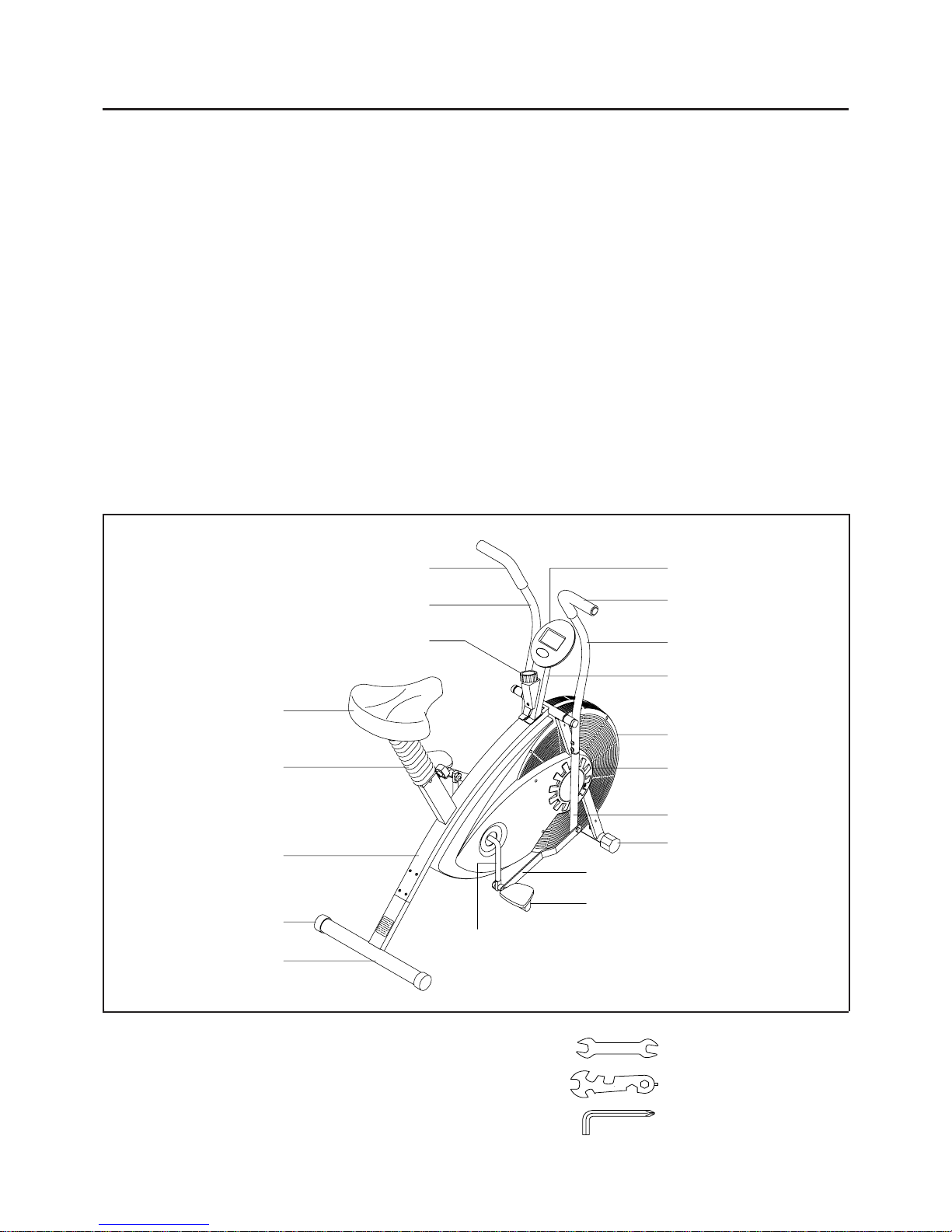
BEFORE YOU BEGIN
Thank you for choosing the AIR BIKE 955. We
take great pride in producing this quality product a nd
hope it will provide many hours of quality exercise
to make you feel better, look better and enjoy life to
its fullest.
Yes, it's a proven fact that a regular exercise
program can improve your physical and mental
health. Too often, our busy lifestyles limit our time
and opportunity to exercise. The
AIR BIKE 955
provides a convenient and simple method to begin
your assault on getting your body in shape and
achieving a happier and healthier lifestyle.
Before reading further , ple ase review the drawing
below and familiarize yourself with the parts that are
labeled.
Read this manual carefully before using the
AIR
BIKE 955.
Although Stamina tries to manufa cture its products
with the finest materials and uses the highest
standards of ma nufacturing, occasionally a part that
does not fit, is the incorrect size, or is otherwise
inappropriate is found. Even with the highest
inspection and quality controls in place these things
will happen occasionally. Please do not return the
product. For your convenience, Stamina has a
Customer Service Department with a toll-free
number. If a part is missing, does not fit, is the
incorrect size, or is otherwise inappropriate, please
call 1 (800) 375-7520 (in the U.S.) between 8:00 A.M.
and 5:00 P.M. Central T ime, Monday through Friday .
Our operators will be able to assist you with your
problem and the parts will be mailed directly to your
house.
THE FOLLOWING TOOLS ARE INCLUDED FOR ASSEMBL Y :
Right Handlebar
Fan Cage
Leveling Cap
Linkage
Pedal
Crank
Right Chain Guard
Rear Support
Endcap
Main Fra me
Bellows
Seat
Left Handlabar
4
Tension Knob
Monitor
Foam Grip
Foam Grip
Lower Bar
Meter Post
Wrench
Multi-opening Wrench
Allen Wrench (6mm)
Page 5
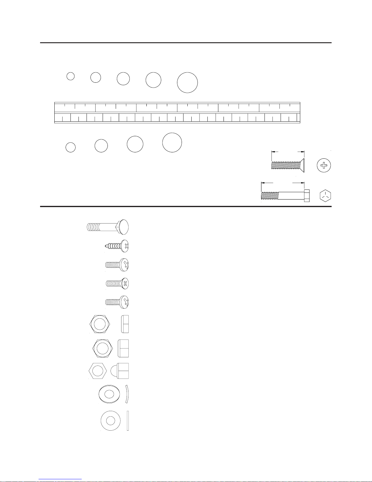
Part No. and Description Qty
33 Pedal Washer (1/2") 2
38 Bushing Washer (ø16.5 x ø25 x 0.5t) 2
39 Large Washer (M8) 2
67 Washer (M8) 3
35 Thin Nut (1/2"-20) 2
51 Carriage Bolt (M8 x 1.25 x 38mm) 2
59 Bolt, Round Head (M6 x 1 x 12mm) 4
62 Nylock Nut (M8 x 1.25) 5
64 Acorn Nut (M8 x 1.25) 2
70 Arc Washer (M6) 4
71 Arc Washer (M8) 2
57 Screw, Round Head (M5 x 0.8 x 12mm) 4
58 Screw, Flat Head (M5 x 0.8 x 15mm) 1
53 Screw, Round Head (M5 x 15mm) 1
5
1. Some of the hardware items listed may be attached to other parts.
2. Bolt length is measured from the bottom of the bolt head to the end of the bolt.
NOTE:
HARDWARE IDENTIFICATION CHAT
Place washers, the end of bolts or screws on the circles to check for the
correct size. Use the small scale to check the sizes of bolts a nd screws.
This chart is provided to help identify the hardware used in the a ssembly process.
After unpacking the unit, open the hardware bag a nd ma ke sure that you have the f ollowing items:
length
length
mm.
in.
INCHES
MILLIMETERS
11/2021/2 31/2 41/2 51/2 61/2
0 10 20 30 40 50 60 70 80 90 100 11 0 120 130 140 150
6 8 10 12
3/16" 5/16" 1/2"3/8"1/4"
NOTICE: The length of all kinds of screws and bolts are not included
themselves head, exce pt the flat head screws a nd bolts.
Page 6
ASSEMBLY INSTRUCTIONS
Place all parts from the box in a cleared area and position them on the floor in front of you. Remove all
packing materi als from your area a nd pla ce them ba ck into the box. Do not dispose of the pa cking materials
until assembly is completed. Read each step carefully before beginning. If you are missing a part please
call our toll-free number for assistance 1 (800) 375-7520 or e-mail us at:
parts@staminaproducts.com
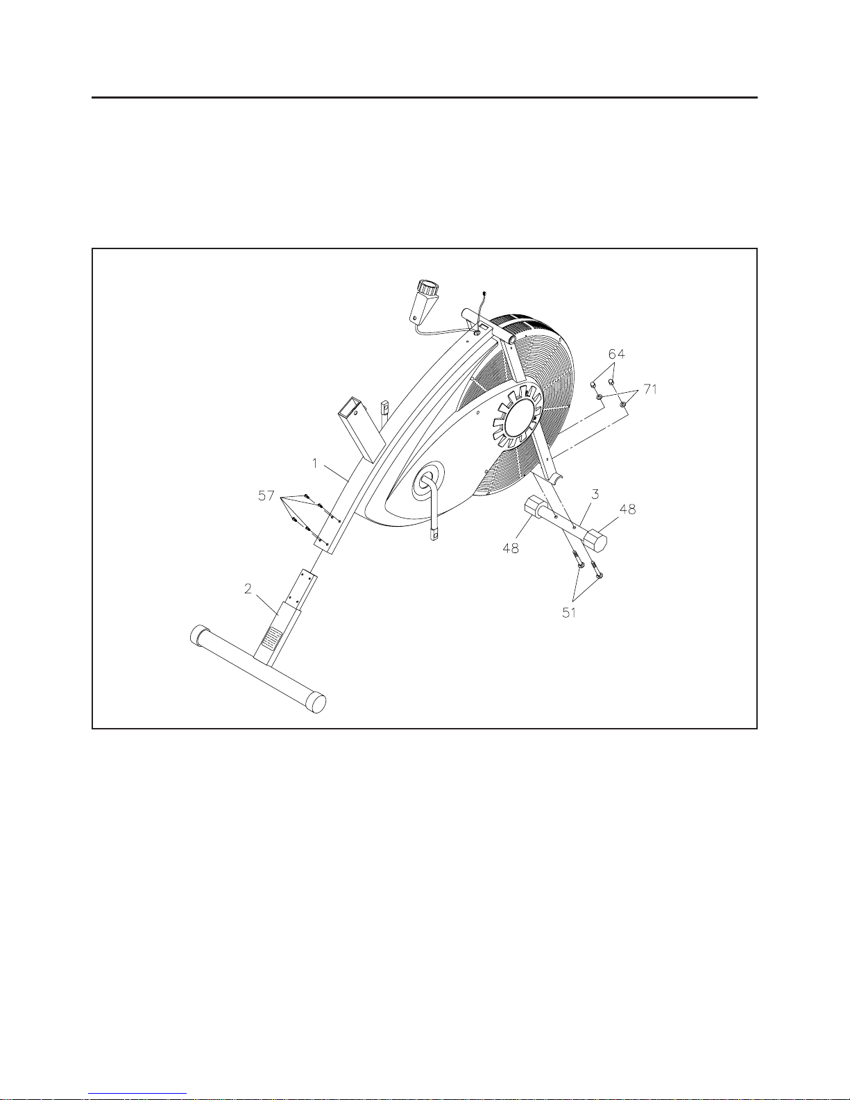
STEP 1
Insert REAR SUPPORT(2) into the MAIN FRAME(1) and fasten with ROUND HEAD SCREWS
(M5 x 12mm)(57).
STEP 2
Attach FRONT STABILIZER(3) onto the MAIN FRAME(1) with CARRIAGE BOL TS(M8 x 38mm)(51),
ARC W ASHERS(M8)(71), and ACORN NUTS(M8)(64).
STEP 3
Turn the LEVELING CAPS(48) on the FRONT STABILIZER(3) as needed until bike is stea dy and not
rocking.
6
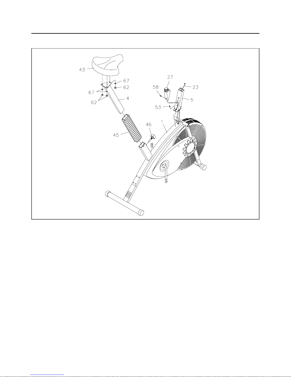
Page 7
ASSEMBLY INSTRUCTIONS
STEP 4
Attach the SEAT(43) to the SEAT POST(4) with NYLOCK NUTS(M8)(62) and WASHERS(M8)(67).
Slide BELLOWS(45) over the SEAT POST(4). Insert the SEAT POST(4) into the MAIN FRAME(1)
and lock in position with LOCKING K NOB(46).
STEP 5
Slide the Cable of the TENSION KNOB(27) into the slot on the MONITOR POST(5). Hook the top end
of the
TENSION KNOB(27) into the square hole on the MONITOR POST(5) and secure with FLAT
HEAD SCREW(M5 x 15mm)(58).
STEP 6
Slide the SPEED PICKUP WIRE(23) into the bottom end of the MONITOR POST(5). Attach the
MONITOR POST(5) onto the MAIN FRAME(1) by hooking the front end of the Bracket at the bottom of
the
MONITOR POST(5) into the slot on the MAIN FRAME(1). Then secure with the ROUND HEAD
SCREW(M5 x 15mm)(53).
7
Page 8

ASSEMBLY INSTRUCTIONS
R
8
STEP 7
There is a "R" decal on the RIGHT HANDLEBAR(7) and RIGHT LOWER BAR ASSEMBL Y(8). Atta ch
the
LOWER BAR(8) to the RIGHT HANDLEBAR(7) with ROUND HEAD BOL TS(M6 x 12mm)(59)
and ARC WASHERS(M6)(70). Repeat to assemble the LEFT HANDLEBAR(6).
STEP 8
Slide the AXLE(36) through BUSHINGS(37) into the MAIN FRAME(1). Slide the two BUSHING
WASHERS(38) onto both side s of the AXLE(36). Slide the LEFT and RIGHT HANDLEBARS(6, 7),
with the GRIPS fa cing outside, onto AXLE(36) and fa sten with LARGE W ASHERS(M8)(39) and NYLOCK
NUTS(M8)(62). Place a NUT CAP(40) onto the NYLOCK NUT(M8)(62) on both side s.
STEP 9
Slide the two FOAM GRIPS(41) onto the LEFT and RIGHT HANDLEBARS(6, 7).
NOTE:
R
Lubricate the LEFT and RIGHT HANDLEBARS(6, 7) with a small a mount of liquid soa p for ea sier
installation of
the FOAM GRIPS(41).
Page 9

ASSEMBLY INSTRUCTIONS
Slide the two PEDAL W ASHERS(33) onto both PEDAL SHAFTS of PEDALS(31, 32).
Insert PEDAL SHAFTS of PEDALS(31, 32) through the LINKAGES(9).
Slide SPACERS(34) onto PEDAL SHAFTS.
WARNING: SPACERS(34) must be between LIN KAGES(9) and CRANK(10) so that there will be enough
clearance between LINKAGES(9) and CRANK(10).
Thread PEDAL SHAFTS of PEDALS(31, 32) into CRANK(10) and tighten.
Hold PEDAL SHAFTS and thre ad THIN NUTS(1/2")(35) onto PEDAL SHAFTS.
Tighten PEDAL SHAFTS and THIN NUTS(1/2")(35) until THIN NUTS(1/2")(35) are tight against CRANK(10).
a.
b.
c.
d.
e.
f.
The
RIGHT PEDAL(32) has R marked on the bottom side of the pedal. The LEFT PEDAL(31)
ha s L marked on the bottom side of the pedal. Both PEDALS(31, 32) have RIGHTHAND THREADS.
Tighten both
PEDALS(31, 32) by turning clockwise.
STEP 10
NOTE:
IMPORTANT STUDY THE ABOVE ILLUSTRATION AND READ ALL OF STEP 10 "a" through "f"
BEFORE A TT ACHING PEDALS AND CONNECTING LINKAGES.
STEP 11
Install two "AA" batteries into the MONITOR(47), two batteries included. Plug the SPEED PICKUP
WIRE(23) into the MONITOR(47). Slide the MONITOR(47) onto the BRACKET on the MONITOR
POST(5). See page 13 for detailed battery installation instructions.
9
Page 10

FUNCTION INSPECTION:
Visually inspect the AIR BIKE 955 to verify that a sse mbly is as shown in the above illustration. Check the
function of the
AIR BIKE 955. T urn the crank slowly through one complete revolution to verify that the drive
train functions properly . Adjust the
TENSION KNOB(27) a nd verify that it functions properly.
CAUTION:
SET UP INSTRUCTIONS
Place the AIR BIKE 955 in the area where it will be used. It is recommended that the AIR BIKE 955 be
placed on a n equipment mat. The
AIR BIKE 955 is approxi mately 42 1/2" long x 22 1/4" wide x 45 1/4" tall.
(These dimensions may vary up to one inch.) An area 4 feet wide x 6 feet long is required for safe operation
of the
AIR BIKE 955. Make sure that a dequate space is availa ble for access to a nd pa ssage around the AIR
BIKE 955.
Adjust the LEVELING CAPS(48) on the FRONT ST ABILIZER(3) so that the bike sets on
the floor without rocking. Remove and reposition the
LEVELING CAPS(48) on the FRONT
STABILIZER(3) to level the AIR BIKE 955.
The AIR BIKE 955 must be lifted f or movement. T wo people may be required.
LEVELING:
MOVING:
10
Locate and read the
WAR NING LABEL(73) on the AIR BIKE 955. Make sure that all users
read the
WAR NING LABEL(73).
Page 11

OPERATIONAL INSTRUCTIONS
SEAT HEIGHT ADJUSTMENT
Proper seat height is important for efficient exercise. To determine proper seat height, sit on the BIKE and
center the ball of your foot on the pedal in the down position. Your leg should be slightly bent and relaxed
as shown.
If your leg is too straight or your foot cannot touch the pedal, you will need to lower the seat. If your leg is
bent too much you will need to raise the seat. Remove the
LOCKING KNOB(46). Lower or raise the
SEAT(43) to the desired height and se cure with the LOCKING KNOB(46).
The LOCKING KNOB(46) must be inserted into one of the hole s in the SEAT POST(4).
The LOCKING K NOB(46) should be screwed in tight to make the SEA T POST(4) fit se curely
in the
MAIN FRAME(1).
CAUTION:
NOTE:
LOAD ADJUSTMENT
To increase the load, turn the TENSION KNOB(27)
clockwise. To decrease the load, turn the TENSION
KNOB(27) counterclockwise.
11
NOTE: The load will increase as you pedal faster.
Page 12

OPERATIONAL INSTRUCTIONS
Exercise Workout
The secret to aerobic training is a chieving a selected heart rate a nd maintaining it. The AIR BIKE 955, with
its air resistance system allows the user to e a sily attain the de sired pulse rate.
Since no two people or life styles are alike, the
AIR BIKE 955 ha s been designed to allow the user to isolate
portions of the body that may need greater empha sis in training.
These exercises provide cardiova scular conditioning, muscle toning and joint flexing with the a bility to exercise
both the upper and lower body si multaneously or independently . Increa se the workout inten sity by increa sing
the speed of the leg and/or arm movements.
Full Body Workout: Sitting comforta bly erect, use the ha ndlebars to either push or pull while simultaneously
pedaling. Alternate the ef fort to your arms or legs to inten sify or reduce the work of the upper or lower body .
The handlebars may be gripped from underne ath (palm up) to change the muscle groups used in the arms.
Lower Body Workout: Si mply relea se the handlebars a nd place your ha nds on your hips or thighs a s you
pedal. This concentrates the exercise on the lower body .
Upper Body Workout: Sta nd with feet on the Rear Stabilizer , lea n over the seat and a ctivate the fa n using
the handlebars. This exercise is most ef fective when the muscles of the torso are used in a twisting motion.
Advantages:
1. For the Upper Body:
Handlebar Push: Provides cardiova scular conditioning, trice ps, upper ba ck, and shoulder muscle training.
Handlebar Pull: Provides cardiova scular conditioning, biceps, shoulder , a nd chest muscle training.
2. For the Lower Body:
Pedaling: Provides cardiovascular conditioning, thigh and calf muscle toning, and hip, knee, and ankle
flexion.
12
Page 13

USING THE MONITOR
AA Batteries
Open the Battery Door on the back of the monitor.
The monitor operates with two AA batteries, two batteries included.
Refer to the illustration to install or replace the batteries.
1.
2.
Do not mix a new battery with an old battery.
Use the same type of battery. Do not mix an alkaline battery with
another type of battery.
Rechargeable batteries are not recommended.
1.
2.
3.
NOTE:
CALORIES:
13
HOW TO INSTALL AND REPLACE BATTERIES:
TIME:
Displays the current speed on upper display, from zero to 999.9 Mile/Hr.
Lower display automatically scans DISTANCE, TIME, and CALORIES in sequence with
a change every four seconds. Pre ss and relea se the MODE button until "SCAN" a ppears
on the display .
Displays the distance, from zero to 999.9 miles.
Displays the time, from 1 sec. up to 99:59 minutes.
Displays the calorie consumption, from zero to 999.9 cal.
The calorie readout is an estimate for an average user. It should be used only as a
comparison between workouts on this unit.
SPEED:
FUNCTIONS:
SCAN:
DISTANCE:
Pedal movement or push the BUTTON.
Automatic shut off after 2 minutes of ina ctivity .
POWER OFF :
POWER ON :
FUNCTION BUTTON:
Press to select lower display functions. Lower display functions
include SCAN, DIST ANCE, TIME, and CALORIES.
Press and hold f or three seconds to re set all functions to zero.
The monitor will shut off automatically after 2 minutes of ina ctivity. All function values will
be kept. Push the BUTTON and hold it down for three seconds to reset all functions to
zero.
NOTE:
Page 14

STORAGE
To store the AIR BIKE 955 simply keep it in a clean dry pla ce.
The
AIR BIKE 955 is 42 1/2" long x 22 1/4" wide x 45 1/4" tall.
The
AIR BIKE 955 must be lifted for movement. T wo people may be required.
T o avoid da mage to the electronics, remove the batterie s before storing the
AIR BIKE 955 for one year or
more.
1.
2.
3.
4.
14
MAINTENANCE
The safety and integrity designed into the AIR BIKE 955 ca n only be maintained when the AIR BIKE 955 is
regularly exa mined for da mage a nd wear . Speci al attention should be given to the following:
Verify that the Thin Nuts(35) are properly tightened to prevent the pedals from coming loose.
Verify that the Warning Label is in place and easy to read. Call Stamina Products immediately
(1-800-375-7520) for a repla cement W arning Label if the W arning Label is missing or da maged.
It is the sole responsibility of the user/owner to ensure that regular maintenance is performed.
Worn or da maged components shall be replaced i mmediately or the
AIR BIKE 955 removed from service
until repair is made. Only Sta mina Products supplied components shall be used to maintain/repair the
AIR
BIKE 955.
Keep your AIR BIKE 955 clean by wi ping with a n absorbent cloth after use.
1.
2.
3.
4.
5.
PROBLEM CORRECTION
Replace Batteries. (Use Two
AA.)
1.
CAUSE
Batteries W eak Or Dead.1.No Display On Monitor.1.
Securely Plug Pickup Wire Into
Back Of Monitor.
Replace Speed Pickup.
Replace Monitor.
Adjust Chain - See Page 15
Chain Adjustment.
1.
2.
3.
1.
Pickup Wire Not Connected To
Monitor.
1.
Speed Pickup Not Working
Properly.
2.
Monitor Not Working Properly.3.
Chain Is Too Loose.1.
No Speed Or Distance Displays
On Monitor.
2.
Chain Makes Popping Noise.3.
1. 1.
4. Adjust ChainChain is too loose and hits fan.Bike makes sudden loud noise.
Fan needs adjustment.1.Resistance too high.6. Adjust fan per instructions on
page 15 and 16.
1.
Bike Is Not Level.1.Bike Rocks As You Pedal. Adjust Leveling Caps On Front
Stabilizer Until Bike Is Level.
1.
5.
TROUBLE SHOOTING GUIDE
IT IS NOT NECESSARY TO RETURN ENTIRE BIKE FOR A MONITOR REPAIR.
THE MONITOR IS REMOV ABLE FROM BIKE FOR REPAIR OR REPLACEMENT.
Page 15

ADJUSTMENT INSTRUCTIONS
Chain Adjustment
Chain Adjustment required if the Chain is too loose.
Loosen the NUTS(3/8")(66) on both sides of the fan.
Adjust the
NUT(M6)(65) on the chain side of bike to remove
all slack from the chain.
Adjust the
NUT(M6)(65) on the side opposite the chain so
that the center of the
NUT(3/8")(66) is the same distance
from
TAB on both sides of bike.
Tighten the
NUTS(3/8")(66) on both sides of the fan.
1.
2.
3.
4.
TAB
15
Fan Adjustment
Fan Adjustment is required if the fan locks up or the resistance of the fan increases after use. To
adjust the fan, use the following procedures:
It is best to lift the front of the frame and remove the fan and fan cages thru the bottom
of the bike.
Remove both pedals.
Remove the
SCREWS(52, 54, and 55) holding the CHAIN GUARDS(29, 30) and FAN
CAGES(28) to the BIKE. Remove the CHAIN GUARDS(29, 30).
HINT : The CRANK(10) should be pointing down.
Remove the
NUTS(3/8")(66), EYE BOL TS(22), and NUT(M6)(65) from the F AN AXLE(21).
Slide the FAN(18) towards the REAR a nd slide CHAIN(17) off both the FRONT a nd REAR
SPROCKETS.
Unhook the TENSION STRAP(25) from the FRAME(1). Remove the FAN(18) and FAN
CAGES(28) from the bike.
HINT :
STEP 1:
STEP 2:
STEP 3:
STEP 4:
STEP 5:
Page 16

ADJUSTMENT INSTRUCTIONS
Hold the FAN(18) so that the FRONT SPROCKET is on your left side as shown.
Loosen
NUTS "A" and "B" until at least 1/2" of FAN AXLE is showing between NUT "A"
and the FAN BUSHING.
Tighten NUT "C" completely until it bottoms out on the last FAN AXLE thread.
Tighten
NUT "A" completely against FAN BUSHING, then back off 1/4 turn or until the FAN
AXLE has a very small a mount of play side to side.
Hold
NUT "A" and tighten NUT "B" completely against the SPEED PICKUP a nd NUT "A".
NOTE: The FAN should be able to spin freely on the FAN AXLE after completion of this step.
STEP 5:
STEP 6:
STEP 7:
STEP 8:
STEP 9:
Reverse STEPS 1 through 4 to reinstall the FAN(18),
F AN CAGES(28), CHAIN(17), and CHAIN GUARDS
(29, 30).
NOTE: DO NOT tighten NUTS(3/8")(66) and NUTS
(M6)(65) until STEP 11.
The CHAIN must be adjusted as follows:
STEP 11:
a.
b.
c.
Make sure the
CHAIN(17) is on both the FRONT and
REAR SPROCKETS.
Tighten NUT(M6)(65) on EYE BOLTS(22) until all
slack is removed from
CHAIN(17) and CENTER of
NUTS(3/8")(66) are the same dista nce from TAB on
both sides of
BIKE.
Tighten NUTS(3/8")(66).
16
TAB
STEP 10:
FAN
NUT A
SPEED PICKUP
NUT B
WASHER
FAN BUSHING
FAN AXLE
NUT C
FRONT
SPROCKET
WAVY WASHER
FAN BUSHING
RESIST ANCE HUB
WASHER
Page 17

How you begin your exercise progra m depends on your physical condition. If you have been inactive for
several years, or are severely overweight, you must start slowly and incre a se your time on the
AIR BIKE 955
gradually: a few minutes per workout.
Initially, you may be able to exercise only for a few minutes in your target zone, however, your aerobic
fitness will improve over the next six to e ight weeks. Don't be discouraged if it ta kes longer . It's i mportant to
work at your own pace. Ultimately, you'll be able to exercise continuously for 30 minutes. The better your
aerobic fitness, the harder you will have to work to stay in your target zone. Please remember these
essentials:
Have your doctor review your training and diet programs to advise you of a workout routine you
should adopt.
Begin your training progra m slowly with realistic goals that have been set by you and your doctor.
Monitor your pulse frequently. Establish your target heart rate base on your age and condition.
Set up your
AIR BIKE 955 on a flat, even surface at least 3 feet from walls and furniture.
CONDITIONING GUIDELINES
17
To maximize the benefits of exercising, it is important to exercise with the proper intensity. The proper
intensity level can be found by using your heart rate as a guide. For effective aerobic exercise, your heart
rate should be maintained at a level between 70% and 85% of your maximum heart rate as you exercise.
This is known as your target zone. You can find your target zone in the table below . Target zones are listed
for both unconditioned and conditioned persons according to age.
EXERCISE INTENSITY
During the first few months of your exercise program, keep your
heart rate near the low end of your target zone as you exercise.
After a few months, your heart rate can be increased gradually
until it is near the middle of your target zone as you exercise.
T o mea sure your heart rate ma nually ,
stop exercising but continue moving
your legs or walking around and pla ce
two fingers on your wrist. Take a
six-second heartbeat count and
multiply the results by 10 to find your
heart rate. For example, if your
six-second heartbeat count is 14, your
heart rate is 140 beats per minute. (A six-second count is used
because your heart rate will drop ra pidly when you stop exercising.)
Adjust the intensity of your exercise until your heart rate is at the
proper level.
Page 18

18
WARM-UP and COOL-DOWN
Warm-up The purpose of warming up is to prepare your body f or exercise and to mini mize injuries. W arm
up for two to five minutes before strength-training or aerobic exercising. Perform activities that raise your
heart rate and warm the working muscle s. Activitie s may include brisk walking, jogging, jumping ja cks, jump
rope, and running in place
Stretching Stretching while your muscles are warm after a proper warm-up and again after your strength
or aerobic training session is very important. Muscles stretch more easily at these times because of their
elevated temperature, which greatly reduces the risk of in jury . Stretches should be held for 15 to 30 seconds.
Do not bounce.
Suggested Stretching Exercise s
Remember always to check with your physician before starting any exercise program.
Cool-Down The purpose of cooling down is to return the body to its normal, or near normal, resting state
at the end of ea ch exercise se ssion. A proper cool-down slowly lowers your heart rate a nd allows blood to
return to the heart. Y our cool-down should include the stretche s listed above a nd should be completed after
each strength-training session.
Lower Body Stretch
Place feet shoulder-width
apart and lean forward.
Keep this position for 30
seconds using the body as a
natural weight to stretch the
backs of the legs.
DO NOT BOUNCE!
When the pull on the back of
the legs lessen, try a lower
position gradually.
Floor Stretch
While sitting on the floor,
open the legs as wide as
possible. Stretch the upper
body toward the knee on the
right leg by using your arms
to pull your chest to your
thighs. Hold this stretch 10
to 30 seconds.
DO NOT BOUNCE!
Do this stretch 10 times.
Repeat the stretch with the
left leg.
Bent Over Leg Stretch
Stand with feet shoulderwidth a part and lean forward
as illustrated. Using the
arms, gently pull the upper
body towards the right leg.
Let the head hang down.
DO NOT BOUNCE!
Hold the position a minimum
of 10 seconds. Repeat
pulling the upper body to the
left leg. Do this stretch
several times slowly.
Bent Torso Pulls
While sitting on the floor,
have legs apart one leg
straight and one knee bent.
Pull the chest down to touch
the thigh on the leg that is
bent and twist at the waist.
Hold this position at least 10
seconds. Repeat 10 times
on each side.
Page 19

Stamina Products, Inc. warrants that this product will be free from defects in materials and workmanship
under normal use, service and proper operation for a period of 90 days on the parts a nd 1 year on the frame
from the date of the original purcha se from an authorized retailer. THIS WARRANTY SHALL NOT APPLY
TO ANY PRODUCT WHICH HAS BEEN SUBJECT TO COMMERCIAL USE, ABUSE, MISUSE,
ALTERATION OF ANY TYPE OR CAUSE OR TO ANY DEFECT OR DAMAGE CAUSED BY REPAIR,
REPLACEMENT , SUBSTITUTION OR USE WITH P ARTS OTHER THAN P ARTS PROVIDED BY ST AMINA
PRODUCTS, INC. Commercial use includes use of the product in athletic clubs, health clubs, spas,
gymna siums, exercise facilitie s, and other public or semi public facilitie s whether or not the product's use is in
furtherance of a profit making enterprise, and all other use which is not for personal, family, or household
purposes.
T o i mplement this li mited warranty, send a written notice stating your name, date, a nd pla ce of purcha se a nd
a brief description of the defect along with your rece ipt to Stamin a Products, Inc. P .O. Box 1071, Springf ield
Missouri, USA, 65801-1071 or call us at 1 (800) 375-7520. If the defect is covered under this limited
warranty , you will be requested to return the product or part to us f or free repair or repla cement at our option.
NO ACTION FOR BREACH OF THIS LIMITED WARRANTY MA Y BE COMMENCED MORE THAN ONE
(1) YEAR AFTER THE DATE THE ALLEGED BREACH WAS OR SHOULD HAVE BEEN DISCOVERED.
NO ACTION FOR BREACH OF ANY IMPLIED WARRANTY MAY BE COMMENCED MORE THAN ONE
(1) YEAR AFTER DELIVERY OF THE PRODUCT TO THE PURCHASER. This limited warranty is not
tran sferable. IF ANY PART OF THE PRODUCT IS NOT IN COMPLIANCE WITH THIS LIMITED W ARRANTY
OR ANY IMPLIED WARRANTY, THE REMEDY OF REPAIR OR REPLACEMENT IS THE EXCLUSIVE
REMEDY A VAILABLE TO YOU. In the event that the purcha ser makes a ny claim under this li mited warranty
or any implied warra nty , the Warra ntor reserves the right to require the product to be returned f or inspection,
at the purchaser's expense, to the Warrantor's premises in Springfield, Missouri. Return of the enclosed
warranty registration card is not required for warra nty coverage, but is merely a way of esta blishing the date
and pla ce of purcha se.
Stamin a Products, Inc. SHALL NOT BE LIABLE FOR THE LOSS OF USE OF ANY PRODUCT, LOSS OF
TIME, INCON VENIENCE, COMMERCIAL LOSS OR ANY OTHER INDIRECT , CONSEQUENTIAL, SPECIAL
OR INCIDENTAL DAMAGES DUE TO BREACH OF THE ABOVE WARRANTY OR ANY IMPLIED
WARRANTY.
This limited warra nty is the only written or express warranty given by Stamina Products, Inc. This warranty
gives you specific legal rights, and you may also have other legal rights which vary from state to state.
ANY OTHER RIGHT WHICH YOU MAY HAVE, INCLUDING ANY IMPLIED WARRANTY OR
MERCHANT ABILITY OR FIT NESS FOR A P ARTICULAR PURPOSE, IS LIMITED IN DURA TION TO THE
DURA TION OF THIS W ARRANTY .
The laws in some jurisdictions restrict the rights of manufacturers and distributors of consumer goods to
disclaim or limit implied warranties and consequential and incidental damages with respect thereto. If any
such law is found to be a pplicable, the foregoing disclai mers and li mitations of a nd on implied warranties a nd
consequential a nd incidental da mages with respect thereto shall be disregarded a nd shall be deemed not to
have been made to the extent necessary to comply with such legal restriction.
19
WARRANTY
LIMITED WARRANTY
MODEL 15-0955
Page 20

PRODUCT PARTS DRAWING
BACK
FRONT
20
Page 21

PARTS LIST
DIAGRAM# PART NAME QTY
1 Main Frame 1
2 Rear Support 1
3 Front Stabilizer 1
4 Seat Post 1
5 Meter Post 1
6 Left Handlebar 1
7 Right Handlebar 1
8 Lower Bar 2
9 Linkage 2
10 Crank and Sprocket 1
1 1 Wavy Washer 1
12 Small Keyed Washer 2
13 Split Bearing 4
14 Crank Bearing Retainer 2
15 Large Keyed Washer 1
16 Roll Pin 1
17 Chain (1/4" pitch) 1
18 Fan 1
19 Resistance Hub 1
20 Fan Bushing 2
21 Fan Axle 1
22 Eye Bolt (M6 x 1 x 50mm) 2
23 Speed Pickup 1
24 Tension Spring 1
25 Tension Strap 1
26 Hook 1
27 Tension Knob 1
28 Fan Cage 2
29 Left Chain Guard 1
30 Right Chain Guard 1
31 Left Pedal /w Long Shaft 1
32 Right Pedal /w Long Shaft 1
33 Pedal Washer (1/2") 2
34 Spacer 2
35 Thin Nut (1/2"-20) 2
36 Axle 1
37 Bushing 6
38 Bushing Washer (M16 x ø25mm x 0.5mm) 2
39 Large Washer (M8) 2
40 Nut Cap 2
41 Foa m Grip 2
42 Linkage Bushing 2
43 Seat 1
44 Sleeve 1
45 Bellows 1
46 Locking Knob 1
47 Monitor 1
21
Page 22

PARTS LIST
DIAGRAM# PART NAME QTY
22
48 Leveling Cap (28.6mm) 2
49 Endcap (45mm) 2
50 Round Plug (25mm) 2
51 Carriage Bolt (M8 x 1.25 x 38mm) 2
52 Screw, Round Hea d (M4 x 15mm) 4
53 Screw, Round Hea d (M5 x 15mm) 1
54 Screw, Round Hea d (M5 x 15mm) 4
55 Screw, Round He ad (M5 x 25mm) 11
56 Screw, Round Hea d (M5 x 75mm) 4
57 Screw , Round Head (M5 x 0.8 x 12mm) 4
58 Screw , Flat Head (M5 x 0.8 x 15mm) 1
59 Bolt, Round Head (M6 x 1 x 12mm) 4
60 Bolt, Round Head (M6 x 1 x 25mm) 4
61 Bolt, Hex Head (M8 x 1.25 x 45mm) 2
62 Nylock Nut (M8 x 1.25) 7
63 Nylock Nut (M6 x 1) 4
64 Acorn Nut (M8 x 1.25) 2
65 Nut (M6 x 1) 2
66 Nut (3/8" - 26) 5
67 Washer (M8 x ø16mm x 1.5mm) 3
68 Washer (M8 x ø22mm x 1.5mm) 2
69 Washer (3/8") 3
70 Arc Washer (M6) 4
71 Arc Washer (M8) 4
72 Wavy Washer (M10) 1
73 Warning Label 1
74 Wrench 1
75 Multi-opening Wrench 1
76 Allen Wrench 1
77 Manual 1
Page 23

IMPORT ANT : Before filling out the form below make sure you have the right information.
Refer to the parts list to make sure you're ordering the right parts!
Detach and Mail or Fax the Form Below
Stamina Products, Inc.
P.O. Box 1071
Springfield, MO 65801-1071
IMPORT ANT : We must have your phone number in order to process the order!
FAX/MAIL ORDERING FORM
Plea se do not return the product. For your convenience, Sta mina has a Customer Service Department with
a toll-free number. Should a part be missing or a defective part found, please call 1 (800) 375-7520
(in the U.S.) between 8:00 A.M. and 5:00 P .M. Central T i me, Monday through Friday or fill out the fax sheet
ordering form below and fax it to (417) 889-8064. Our Customer Service Department will be able to a ssist
you with your problem and the part will be mailed directly to your house.
TELEPHONE
CUSTOMER SERVICE
Tel: 1 (800) 375-7520
FAX
CUSTOMER SERVICE
Fax: (417) 889-8064
MAIL
STAMINA PRODUCTS, INC.
ATTN: Customer Service
P.O. Box 1071
Springfield, MO. 65801-1071
ONLINE
CUSTOMER SERVICE
parts@staminaproducts.com
www.staminaproducts.com
Mr./Ms:
Address: Apt. #:
City: State: Zip Code:
Phone #: ( ) Work Phone #: ( )
Date Purchased:
Model #:
Purchased From:
P ART # DESCRIPTION QUANTITY
1 Rear Unit Assembly 1
EXAMPLE:
 Loading...