

Page 1
55-1522
STAMINA PRODUCTS
MADE IN CHINA
Product May Vary Slightly
From Pictured.
CAUTION:
! WARNING !
Exercise can present a he alth
risk. Consult a physician
before beginning any exercise
program with this equipment.
If you feel faint or dizzy,
immediately discontinue use
of this equipment. Serious
bodily injury can occur if this
equipment is not assembled
and used correctly. Serious
bodily injury can also occur if
all instructions are not
followed. Keep others and
pets away from equipment
when in use. Always make
sure all bolts and nuts are
tightened prior to each use.
Follow all safety instructions in
this manual.
When calling for parts or
service, please specify the
following number.
Weight on this product should not exceed 300 lbs.
Class H equipment: This equipment is for home
use only. It is not for commercial use.
1.
2.
2006, 02
2040 N. Alliance, Springfield, MO 65803
Customer Service Number
1 (800) 375-7520
www.staminaproducts.com
This Product is Produced Exclusively by
2006 Stamina Products, Inc.
Owner's Manual
Page 2

SAFETY INSTRUCTIONS
2
WARNING:
1.
2.
3.
4.
5.
6.
7.
8.
9.
10.
11.
12.
13.
14.
15.
16.
17.
18.
Read the Warning Label posted on the Front Base Frame.
The Core Training Inversion System should only be used after a thorough review of the Owner's
Manual.
We recommend that two people be available for assembly of this product.
Do not use the Core Training Inversion System alone. Always have a helper available in case
assistance is needed in recovering from the decline position.
Always use the Seat Belt. Make sure the Seat Belt is securely fastened before inverting.
You must understand how to recover from the inverted position before using the Core Training
Inversion System. Read the LEVER OPERATION section on page 15
BEFORE using the Core
Training Inversion System.
Do not allow children to use or play on the Core Training Inversion System.
Keep small children and pets away from the Core Training Inversion System at all times.
The Core Training Inversion System should not be used by persons weighing more tha n 300 lbs.
The Core Training Inversion System should not be used by persons over 6 feet 6 inches tall.
Keep hands and feet away from moving parts.
It is recommended that you place this exercise equipment on an equipment mat.
Use the Core Training Inversion System only on a level surface.
W ear appropriate clothing when exercising; do not wear loose clothing that could become caught in
the Core Training Inversion Syste m.
Be sure that there is enough room for the seat to rotate completely.
Use the Core Training Inversion System only as de scribed in the manual.
The safety level of the Core Training Inversion System can be maintained only if it is examined
regularly for damage and wear.
This equipment is for home use only. It is not for commercial use.
Maintenance Instructions 16
Warranty 17
Product Parts Drawing 18
Parts List 19
Notes 21
Fax/Mail Ordering Form 22
Safety Instructions 2
Before Y ou Begin 4
Hardware Identification Chart 5
Assembly Instructions 6
Operational Instructions 13
Storage 16
TABLE OF CONTENTS
Page Page
Extreme obesity
Glaucoma, retinal detachment or conjunctivitis
Pregnancy
Spinal injury, Cerebral Sclerosis, or acutely swollen joints
Middle ear infection
High blood pressure, Hypertension, Recent stroke or Transient ischemic attack
Heart or circulatory disorders for which you are being treated
Hiatus hernia or Ventral hernia
Bone weaknesses including Osteoporosis, Unhealed fractures, Medullary pins, or
Surgically implanted orthopedic supports.
Use of anti-coagulants including Aspirin in high doses.
WARNING: Before using this equipment you should consult with your personal physician to see if
inversion equipment is appropriate for you. Do not use this equipment without your physician's
approval. Do not use this equipment if you have any of the following conditions or ailments:
To reduce the risk of serious injury, read the following safety instructions before
using the
Core Training Inversion System.
Page 3

THANK YOU FOR PURCHASING THE
Core Training Inversion System
Simply follow the few assembly instructions set forth in this manual.
Within a few minutes you will be getting
your body into shape and on your way to achieving
a ha ppier and healthier lifestyle.
Should you have any que stions,
please call our Customer Service Department toll-free number,
1 (800) 375-7520
Monday - Friday, 8:00 A.M. - 5:00 P.M., Central Time.
CALL US FIRST
3
Page 4
BEFORE YOU BEGIN
Thank you for choosing the Core Training
Inversion System. W e ta ke great pride in producing
this quality product and hope it will provide many
hours of quality exercise to make you feel better , look
better and enjoy life to its fullest.
Yes, it's a proven fact that a regular exercise
program can improve your physical and mental
health. Too often, our busy lifestyles limit our time
and opportunity to exercise. The Core Training
Inversion System provides a convenient a nd simple
method to begin your assault on getting your body in
sha pe and a chieving a ha ppier and healthier lifestyle.
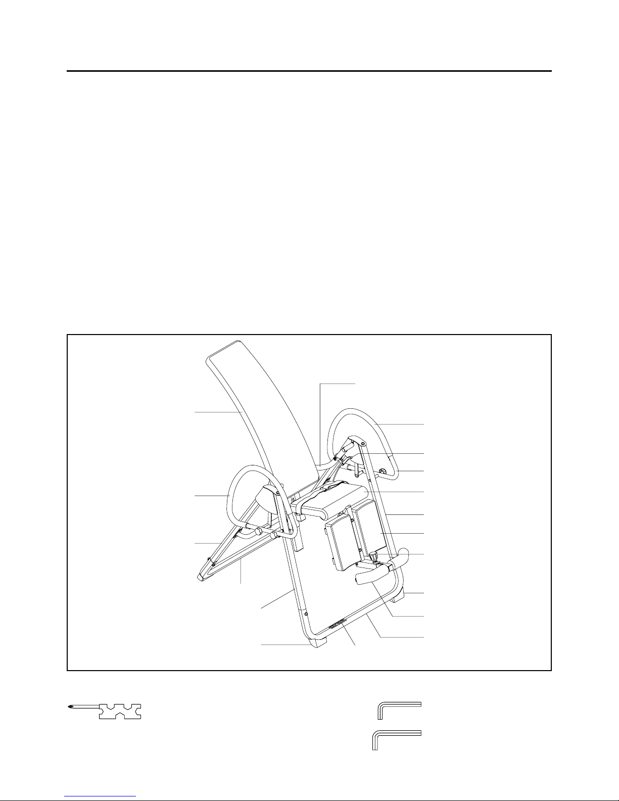
Before reading further, please review the drawing
below and familiarize yourself with the parts that are
labeled.
Read this manual carefully before using the Core
Training Inversion System.
Although Stamina tries to manufa cture its products
with the finest materials and uses the highest
standards of ma nufacturing, occasionally a part that
does not fit, is the incorrect size, or is otherwise
inappropriate is found. Even with the highest
inspection and quality controls in place these things
will happen occasionally. Please do not return the
product. For your convenience, Stamina has a
Customer Service Department with a toll-free
number. If a part is missing, does not fit, is the
incorrect size, or is otherwise inappropriate, please
call 1 (800) 375-7520 (in the U.S.) between 8:00 A.M.
and 5:00 P.M. Central Ti me, Monday through Friday .
Our operators will be able to assist you with your
problem and the parts will be mailed directly to your
house.
4
Left Pivot Arm
Stand B
Right Front Frame
Handrail
Back Cushion
Stand A
Handrail
Lever
Seat Cushion
Leg Support Cushion
Rear Fra me
Foam Pad
Left Front Frame
THE FOLLOWING TOOLS ARE INCLUDED FOR ASSEMBLY :
Allen Wrench (4mm)
Allen Wrench (6mm)
Combination Wrench
Rear Ba se Frame
Left Handrail Support
Spring Knob
Front Base Frame
Warning Label
Page 5
5
Part No. and Description Qty
40 Acorn Nut (M5 x 0.8) 1
54 Bolt, Flat Head (M6 x 1 x 50mm) 4
38 Screw, Round He ad (M5 x 0.8 x 18mm) 1
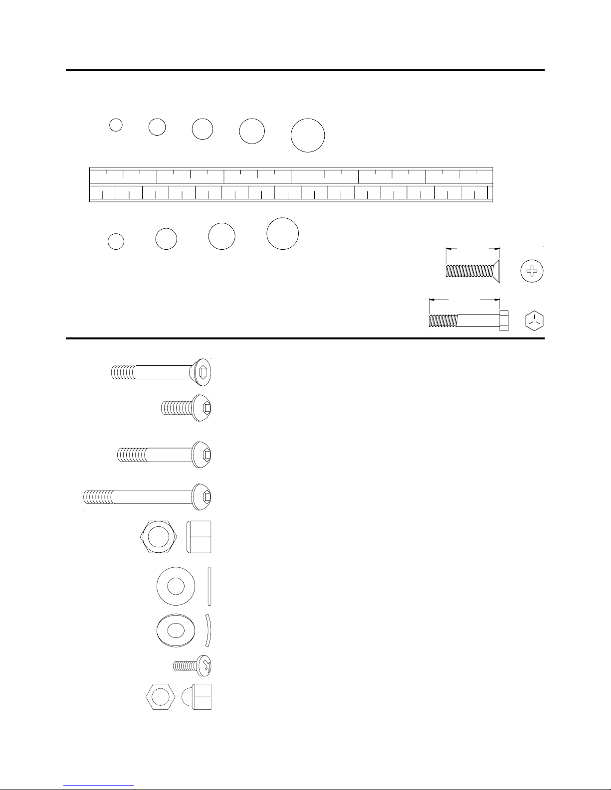
HARDWARE IDENTIFICATION CHART
Place washers, the end of bolts or screws on the circles to check for the
correct size. Use the small scale to check the sizes of bolts and screws.
This chart is provided to help identify the hardware used in the assembly process.
After unpacking the unit, open the hardware bag and make sure that you have the following items:
length
length
mm.
in.
INCHES
MILLIMETERS
11/2021/2 31/2 41/2 51/2 61/2
0 10 20 30 40 50 60 70 80 90 100 110 120 130 140 150
6 8 10 12
3/16" 5/16" 1/2"3/8"1/4"
NOTICE: The length of all kinds of screws and bolts are not included
themselves head, except the flat head screws and bolts.
1. Some of the hardware items listed may be attached to other parts.
2. Bolt length is measured from the bottom of the bolt head to the end of the bolt.
NOTE:
69 Arc Washer (M8) 4
55 Bolt, Button Head (M6 x 1 x 15mm) 2
58 Bolt, Button Head (M8 x 1.25 x 15mm) 22
59 Bolt, Button Head (M8 x 1.25 x 30mm) 8
56 Bolt, Button Head (M6 x 1 x 47mm) 1
57 Bolt, Button Head (M6 x 1 x 65mm) 2
60 Bolt, Button Head (M8 x 1.25 x 55mm) 4
61 Bolt, Button Head (M8 x 1.25 x 60mm) 4
62 Bolt, Button Head (M10 x 1.5 x 90mm) 2
63 Nylock Nut (M6 x 1) 6
64 Nylock Nut (M8 x 1.25) 10
65 Nylock Nut (M10 x 1.5) 2
66 Washer (M6) 11
67 Washer (M8) 42
68 Washer (M10) 2
39 Washer (M5) 1
Page 6
ASSEMBLY INSTRUCTIONS
Place all parts from the box in a cleared area and position them on the floor in front of you. Remove all
packing materi als from your area a nd pla ce them ba ck into the box. Do not dispose of the pa cking materials
until assembly is completed. Read each step carefully before beginning. If you are missing a part please
call our toll-free number for assistance 1 (800) 375-7520 or e-mail us at :
parts@staminaproducts.com
6
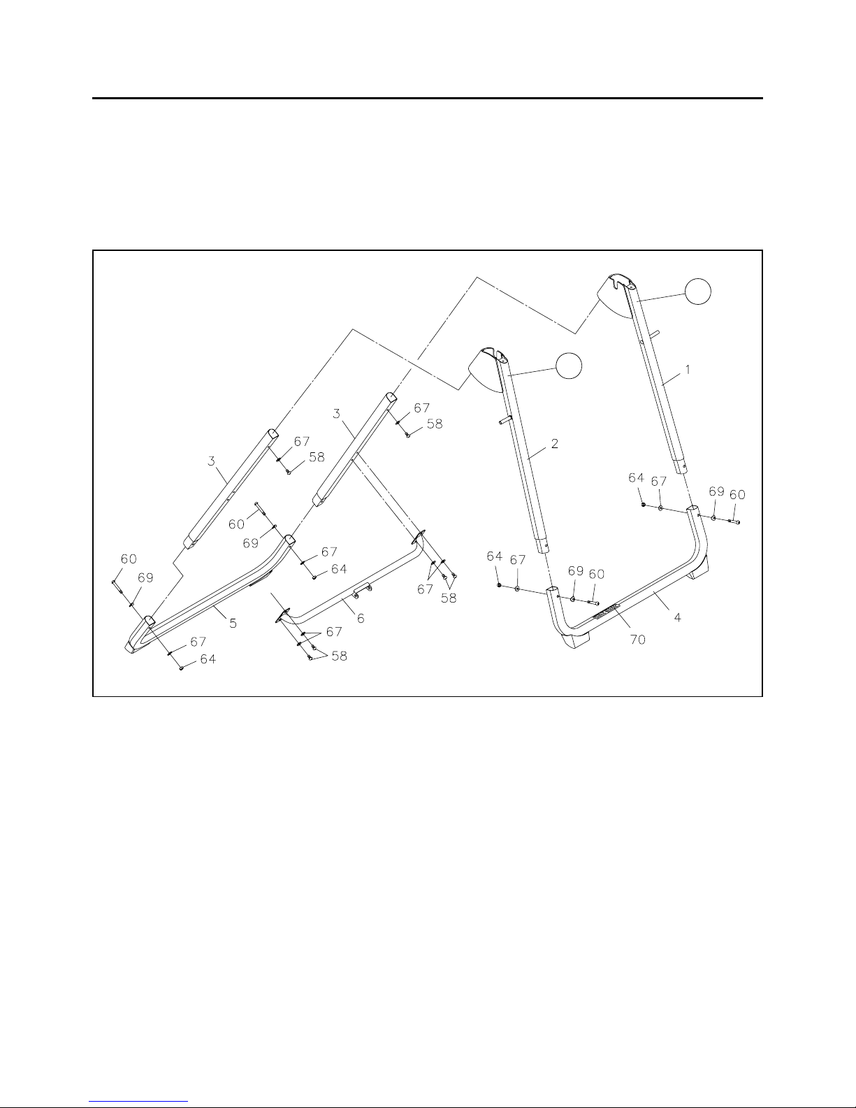
STEP 1: There is a "L" decal on the LEFT FRONT FRAME(1), and a "R" de cal on the RIGHT FRONT
FRAME(2). Insert the LEFT and RIGHT FRONT FRAMES(1, 2) into the FRONT BASE FRAME(4),
the one with WARNING LABEL(70), and secure with BUTTON HEAD BOLTS(M8 x 55mm)(60),
ARC WASHERS(M8)(69), WASHERS(M8)(67), and NYLOCK NUTS(M8)(64). Insert the REAR
FRAMES(3) into the REAR BASE FRAME(5) and se cure with BUTTON HEAD BOL TS(M8 x 55mm)
(60), ARC W ASHERS(M8)(69), W ASHERS(M8)(67), and NYLOCK NUTS(M8)(64). Do not tighten
the bolts until
STEP 3.
STEP 2: Slide the upper ends of the REAR FRAMES(3) into the Brackets on the FRONT FRAMES
(1, 2) and secure with BUTTON HEAD BOLTS(M8 x 15mm)(58), and WASHERS(M8)(67). Do not
tighten the bolts until
STEP 3.
STEP 3
NOTE:
Attach the CROSSING FRAME(6) onto the REAR FRAMES(3) with BUTTON HEAD BOLTS
(M8 x 15mm)(58) and WASHERS(M8)(67). Tighten all of the bolts.
Attach the CROSSING FRAME(6) so that the long flat surface of the center bracket is on top as
shown in the illustration.
L
R
Page 7
ASSEMBLY INSTRUCTIONS
7
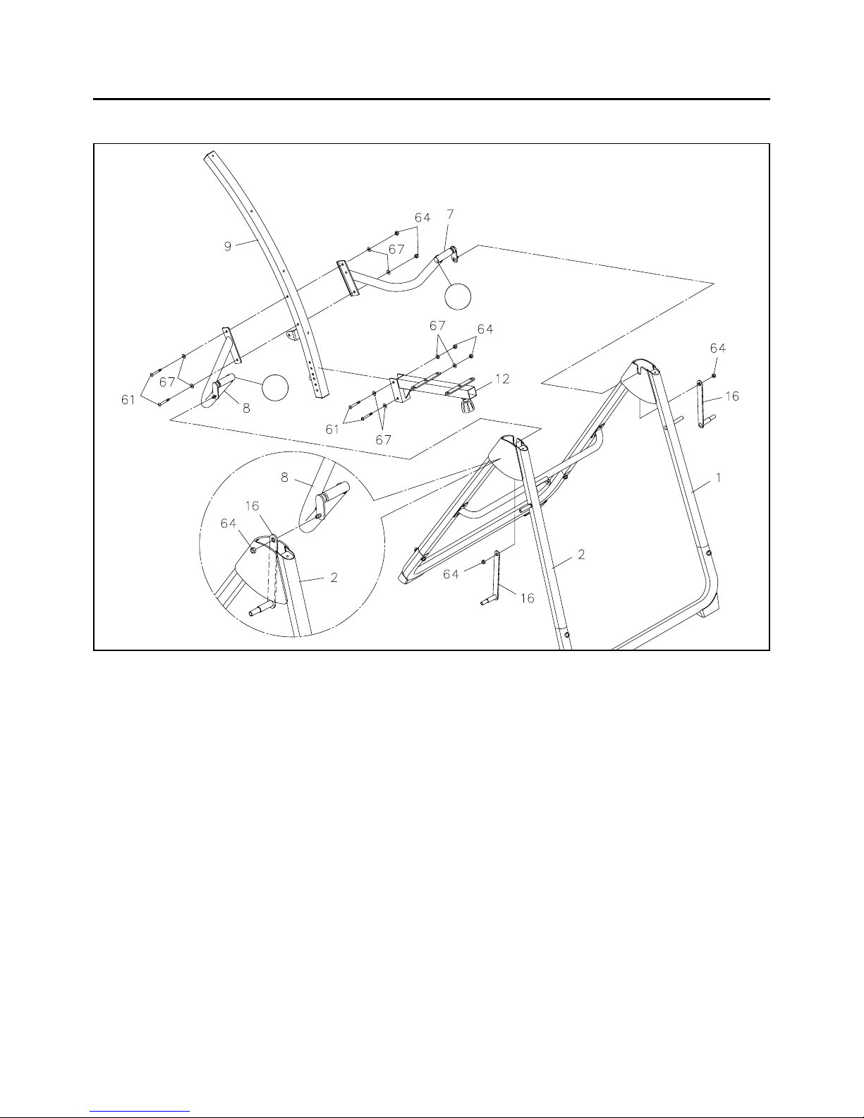
STEP 4
There is a "L" decal on the LEFT PIVOT ARM(7), and a "R" decal on the RIGHT PIVOT ARM(8).
Refer to the Inset drawing. Insert the LINKAGE(16) through the bra cket on the RIGHT FRONT FRAME(2),
then attach the LINKAGE(16) to the RIGHT PIVOT ARM(8) with NYLOCK NUT(M8)(64). DO NOT
OVER TIGHTEN THE NUT.
Attach the RIGHT PIVOT ARM(8) onto the RIGHT FRONT FRAME(2) by sliding the slots in the end of
the
RIGHT PIVOT ARM(8) into the slot on the RIGHT FRONT FRAME(2). Repeat on other side.
STEP 5: Pla ce the BACK FRAME(9) between the Brackets of the LEFT a nd RIGHT PIVOT ARMS(7,
8) and secure with BUTTON HEAD BOLTS(M8 x 60mm)(61), NYLOCK NUTS(M8)(64), and
WASHERS(M8)(67).
STEP 6: Attach the SEAT FRAME(12) onto the BACK FRAME(9) with BUTTON HEAD BOLTS
(M8 x 60mm)(61), NYLOCK NUT(M8)(64), and WASHERS(M8)(67).
SEAT FRAME HEIGHT ADJUSTMENT
There are adjustment holes on the BACK FRAME(9) allowing you to position the SEAT FRAME(12) at
three different heights. In the highest position, it is ea sier to invert but more dif ficult to recover from inversion.
In the lowest position, it is more difficult to invert but easier to recover from inversion. T all people may prefer
the lowest position and shorter people may prefer the highest position.
L
R
Page 8

ASSEMBLY INSTRUCTIONS
8
STEP 7
Attach the SLIDER SUPPORT(11) onto the Bracket on the CROSSING FRAME(6) with BUTTON
HEAD BOLT(M10 x 90mm)(62), NYLOCK NUT(M10)(65), and WASHER(M10)(68).
STEP 8
Straighten the CABLE(35) on the LEVER(36). Refer to the Inset drawing. The LEVER(36) should be
attached 4.5 inches lower tha n the shaft on the
LEFT PIVOT ARM(7). To attach the LEVER(36) onto the
LEFT PIVOT ARM(7), hook the CLIP(37) into slot in the LEVER(36) and secure the LEVER(36) in
position with
ROUND HEAD SCREW(M5 x 18mm)(38), W ASHER(M5)(39), and ACORN NUT(M5)
(40).
STEP 9
Gra sp the LEVER(36) and then Insert the BACK SUPPORT BAR(10) into the SLIDER SUPPORT(1 1).
Release the LEVER(36) to lock the BACK SUPPORT BAR(10) in one of the adjustment holes. Swing
the
BACK FRAME(9) to aline the Bracket on the BACK FRAME(9) with the Bushings on the top of the
BACK SUPPORT BAR(10), then secure with BUTTON HEAD BOLT(M10 x 90mm)(62), NYLOCK
NUT(M10)(65), and WASHER(M10)(68).
Page 9

ASSEMBLY INSTRUCTIONS
9
STEP 10
Attach the SUPPORT PLA TES(23) onto the BACK FRAME(9) with FLAT HEAD BOL TS(M6 x 50mm)
(54), WASHERS(M6)(66), and NYLOCK NUTS(M6)(63).
NOTE:
A
B
C
D
The lowest SUPPORT PLATE(23) is attached with a FLAT HEAD BOLT(M6 x 50mm)(54),
no washer and nut needed.
STEP 11
The BACK FRAME(9) is curved. Follow sequence A, B, C, and D as shown in the illustration to attach
the
BACK CUSHION(24) to the SUPPORT PLA TES(23) with BUTTON HEAD BOL TS(M8 x 15mm)
(58) and WASHERS(M8)(67).
Page 10

ASSEMBLY INSTRUCTIONS
10
STEP 12: Refer to the Bottom View in the illustration. Attach the BELT GUIDES(27) onto the SEAT
CUSHION(25) with BUTTON HEAD BOLTS(M8 x 15mm)(58) and WASHERS(M8)(67). Make the
Securing Pad fa ce down and insert the
SEA T BEL T(26) through the BEL T GUIDES(27) under the SEAT
CUSHION(25). Move the SEA T CUSHION(25) to the center of the SEA T BEL T(26). Atta ch the SEAT
CUSHION(25) onto the SEAT FRAME(12) with BUTTON HEAD BOLTS(M8 x 15mm)(58) an d
WASHERS(M8)(67).
Securing Pad
must face down
BOTTOM VIEW
STEP 13: Rotate the SPRING KNOB(29) on the SEAT FRAME(12) counter clockwise until the knob
portion can be pulled. Pull down the
SPRING KNOB(29) then insert the LEG SUPPORT FRAME(13)
into the SEA T FRAME(12). Relea se the SPRING KNOB(29) to lock the LEG SUPPORT FRAME(13)
in one of the adjustment holes. Rotate the SPRING KNOB(29) clockwise to lock the LEG SUPPORT
FRAME(13) securely.
STEP 14: Rotate the SPRING KNOB(29) on the LEG SUPPORT FRAME(13) counter clockwise until
the knob portion can be pulled. Pull the
SPRING KNOB(29) then slide the FOAM SUPPORT(15)
completely into the LEG SUPPORT FRAME(13). Put a WASHER(M6)(66) onto the BUTT ON HEAD
BOLT(M6 x 47mm)(56) and insert the bolt halfway through the square tube on the LEG SUPPORT
FRAME(13), slide the bolt through the loop on the end of the SPRING(32), slide the bolt through the
square tube and secure with
NYLOCK NUT(M6)(63) and WASHERS(M6)(66). Press the SQUARE
PLUG(49) into the LEG SUPPORT FRAME(13). Slide the FOAM PADS(30) onto both sides of the
FOAM SUPPORT(15).
Page 11

ASSEMBLY INSTRUCTIONS
11
STEP 15
Attach the CUSHION SUPPORT TUBES(14) onto the LEG SUPPORT FRAME(13) with BUTTON
HEAD BOLTS(M6 x 65mm)(57), WASHERS(M6)(66), and NYLOCK NUTS(M6)(63).
STEP 16
Attach the LEG SUPPORT CUSHIONS(28) onto the CUSHION SUPPORT TUBES(14) with BUTTON
HEAD BOLTS(M8 x 30mm)(59) and WASHERS(M8)(67).
Page 12

ASSEMBLY INSTRUCTIONS
12
STEP 17
Attach the LEFT and RIGHT HANDRAIL ASSEMBLIES(17, 18) onto the SHAFTS in the LEFT and
RIGHT FRONT FRAMES(1, 2) and the LINKAGES(16) with the LOCKING KNOBS(21).
STEP 18
Verify that the handlebars function correctly before using the Core Training Inversion System. Move
the
BACK CUSHION(24) backward toward the inverted position. The HANDRAILS(17, 18) must move
forward a s the
BACK CUSHION(24) moves backward. If the HAND RAILS(17, 18) do not move forward
check
ASSEMBLY STEPS 4 and 17.
STEP 19
Attach the COVER PLATES(22) onto the LEFT and RIGHT FRONT FRAMES(1, 2) by hooking the
COVER PLATES(22) into the slots on the Brackets on the LEFT a nd RIGHT FRONT FRAMES(1, 2)
and secure with BUTTON HEAD BOLTS(M6 x 15mm)(55) and WASHERS(M6)(66).
Page 13

13
OPERATIONAL INSTRUCTIONS
GENERAL PRECAUTIONS
Do not use the Core Training Inversion System alone. Always have a helper available in case
assistance is needed in recovering from the decline position.
Check the
LEVER(36), CABLE(35), and SPRING PIN(34). Make sure the system works smoothly
BEFORE using the Core Training Inversion System.
Make sure that the FOAM PADS(30) and the LEG SUPPORT CUSHIONS(28) are holding your feet
properly.
Make sure that there is enough room f or the seat to rotate completely.
1.
2.
3.
4.
Proper adjustment of the
LEG SUPPORT
CUSHIONS(19) is very important.
Loosen the
SPRING KNOB(29) under the SEAT
FRAME(12).
Pull down the SPRING KNOB(29) and slide the
LEG SUPPORT FRAME(13) to adjust.
Sit on the machine to ma ke sure you feel comfortable
with the leg support.
Tighten the
SPRING KNOB(29) after adjustment.
1.
2.
3.
4.
SEAT FRAME HEIGHT ADJUSTMENT
LEG SUPPORT ADJUSTMENT
There are adjustment holes on the BACK FRAME
(9) allowing you to position the SEA T FRAME(12) at
three different heights.
In the highest position, it is easier to invert but more
difficult to recover from inversion. In the lowest position,
it is more difficult to invert but easier to recover from
inversion. Tall people may prefer the lowest position
and shorter people may prefer the highest position.
To adjust the height, remove the
BUTTON HEAD
BOLTS(M8 x 60mm)(61), NYLOCK NUTS(M8)
(64), and WASHERS(M8)(67) from the SEAT
FRAME(12). Then atta ch the SEAT FRAME(12) in
another position with the same hardware.
Page 14

OPERATIONAL INSTRUCTIONS
FOAM PAD USE AND ADJUSTMENT
Place your feet under the FOAM PADS(30) with your legs
between the
FOAM PADS(30) and the LEG SUPPORT
CUSHIONS(28).
Loosen the SPRING KNOB(29). Pull the SPRING KNOB(29)
and slide the FOAM P AD SUPPORT(15) toward you until your
legs are properly held between the
FOAM P ADS(30) and LEG
SUPPORT CUSHIONS(28).
T o relea se your feet or relax the grip, loosen a nd pull the SPRING
KNOB(29), then slide the FOAM PAD SUPPORT(13)
forward.
1.
2.
3.
14
THE SEAT BELT
CAUTION:
THE HANDRAILS
Always use the seat belt. Make sure the seat belt is
securely fastened before inverting.
Sit on the
SEAT CUSHION(25). Place both ends of the SEAT
BELT(26) on top of your upper legs and insert the end of the belt
through the metal rings a s shown in the illustration. Fold the end of
the belt over and secure it in pla ce with the hook a nd loop materi al.
WAR NING:
The Core T raining Inversion System feature s a set of Handrails
for added convenience a nd safety . The Ha ndrails are connected to
the Inversion Chair with linkages so that pulling on the Handrails
will move the Inversion Chair away from the inverted position toward
the upright position.
The
HANDRAILS(19) are to help you invert and help you return
from inversion to the upright position. Pull the
LEVER(36), gra sp
the right
HANDRAILS(19), and pull yourself to the upright position.
Make sure that the Handrails are functioning properly
before using The
Core Training Inversion Syste m.
Page 15

Start by sitting on the machine and leaning back on the back cushion with your hands at your side, or
resting on your thighs.
Pull and hold the LEVER(36) with your left ha nd. Use the handrail a nd your right hand to rotate the BACK
CUSHION(24) slowly backward.
Relea se the LEVER(36) to lock the Core Training Inversion Syste m in one of the four inversion positions.
It is recommended that the Core Training Inversion System be used for five or ten minutes each
morning, and again each evening.
Pull the LEVER(36), gra sp the right HANDLEBAR(19), and pull yourself to the upright position.
USING THE SEATED INVERSION SYSTEM
1.
2.
3.
4.
5.
15
OPERATIONAL INSTRUCTIONS
If you have difficulty pulling the LEVER(36),
you can take pressure off the spring pin by
pushing yourself backward or pulling yourself
forward.
Y ou must understand how to recover from the inverted position bef ore using the
Core Training
Inversion System. Read the LEVER OPERATION section above BEFORE using the
Core Training Inversion System.
CAUTION:
LEVER OPERATION
Pull the LEVER(36) with your left hand. Use your right
hand and the right handrail to push the
BACK
CUSHION(24) backward slowly. Release the
LEVER(36) to lock the Core Training Inversion
System in one of the four inversion positions as shown
in the illustrations below.
To return to the upright position, pull and hold the
LEVER(36) with your left hand. Use your right hand
and the right handrail to pull yourself to the upright
position.
NOTE:
1. 3. 4.2.
Position 1
Position 2
Position 3
Position 4
Seat Cushion
( Degrees From Horizontal )
Top of Back Cushion
( Degrees From Vertical )
Bottom of Back Cushion
( Degrees From Vertical )
59 degrees
71 degrees
84 degrees
96 degrees
64 degrees
76 degrees
89 degrees
101 degrees
97 degrees
109 degrees
122 degrees
134 degrees
Page 16

OPERATIONAL INSTRUCTIONS
SUGGESTIONS FOR USE
Begin slowly: Invert with the least amount of inversion angle. Stay inverted only as long as you are
comfortable. Return upright slowly.
Make gra dual changes: Increa se the a ngle only if it is comfortable. Increa se the a ngle only one adjustment
hole at a time. Increa se the ti me of use 1-2 minutes up to ten over a period of weeks. Add stretching a nd
sit-up exercises only after you are comfortable with inversion.
Watch your body: Come up slowly, dizziness after a session means you came up to fast. Wait awhile
after eating before using the Core Training Inversion System. If you get nauseous, do not fight it,
come up as soon as you feel queasy.
Invert regularly: We recommend one or two times a day depending upon your current condition. Try to
schedule it at the sa me times each day.
1.
2.
3.
4.
16
It is the sole responsibility of the user/owner to ensure that regular maintenance is performed.
Check the W arning Label, Back Support Bar, Seat Belt, Locking Knobs, Spring Knobs, Cushions, Foam
Pads, Spring, Lever, Cable, and Spring Pin for damage and wear .
Verify that all nuts a nd bolts are present a nd properly tightened. Repla ce missing nuts a nd bolts. T ighten
loose nuts and bolts.
Worn or damaged components shall be replaced immediately or the Core Training Inversion System
removed from service until repair is made.
Only Sta mina Products supplied components shall be used to maintain/repair the Core Training Inversion
System.
Keep your Core Training Inversion System clean by wiping with an absorbent cloth after use.
1.
2.
3.
4.
5.
6.
MAINTENANCE
The safety and integrity designed into the Core Training Inversion System can only be maintained
when the
Core Training Inversion Syste m is regularly exa mined for da mage a nd wear. Spe cial attention
should be given to the following:
To store the
Core Training Inversion System simply keep it in a clean dry place.
Move the
Core Training Inversion System by lifting the frame and moving slowly.
NOTE: T wo people are required to move the Core Training Inversion System.
1.
2.
STORAGE
Page 17

LIMITED WARRANTY
MODEL 55-1522
WARRANTY
17
Stamina Products, Inc. warrants that this product will be free from defects in materials and workmanship
under normal use, service and proper operation for a period of 90 days on the parts and 5 years on the
frame from the date of the original purchase from an authorized retailer. THIS WARRANTY SHALL NOT
APPLY TO ANY PRODUCT WHICH HAS BEEN SUBJECT TO COMMERCIAL USE, ABUSE, MISUSE,
ALTERATION OF ANY TYPE OR CAUSE OR TO ANY DEFECT OR DAMAGE CAUSED BY REPAIR,
REPLACEMENT , SUBSTITUTION OR USE WITH P ARTS OTHER THAN P ARTS PROVIDED BY ST AMINA
PRODUCTS, INC. Commercial use includes use of the product in athletic clubs, health clubs, spas,
gymnasiums, exercise facilities, and other public or semipublic facilities whether or not the product's use is
in furtherance of a profit making enterprise, and all other use which is not for personal, fa mily, or household
purposes.
T o i mplement this li mited warranty, send a written notice stating your name, date, a nd pla ce of purcha se a nd
a brief description of the defect along with your rece ipt to Stamin a Products, Inc. P .O. Box 1071, Springf ield
Missouri, USA, 65801-1071 or call us at 1 (800) 375-7520. If the defect is covered under this limited
warranty , you will be requested to return the product or part to us f or free repair or repla cement at our option.
NO ACTION FOR BREACH OF THIS LIMITED WARRANTY MA Y BE COMMENCED MORE THAN ONE
(1) YEAR AFTER THE DATE THE ALLEGED BREACH WAS OR SHOULD HAVE BEEN DISCOVERED.
NO ACTION FOR BREACH OF ANY IMPLIED WARRANTY MAY BE COMMENCED MORE THAN ONE
(1) YEAR AFTER DELIVERY OF THE PRODUCT TO THE PURCHASER. This limited warranty is not
transferable. IF ANY PART OF THE PRODUCT IS NOT IN COMPLIANCE WITH THIS LIMITED
WARRANTY OR ANY IMPLIED WARRANTY, THE REMEDY OF REPAIR OR REPLACEMENT IS THE
EXCLUSIVE REMEDY AVAILABLE T O YOU. In the event that the purchaser makes any claim under this
limited warranty or a ny implied warra nty , the Warra ntor reserves the right to require the product to be returned
for inspection, at the purchaser's expense, to the Warrantor's premises in Springfield, Missouri. Return of
the enclosed warranty registration card is not required for warranty coverage, but is merely a way of
establishing the date and place of purchase.
Stamin a Products, Inc. SHALL NOT BE LIABLE FOR THE LOSS OF USE OF ANY PRODUCT, LOSS OF
TIME, INCONVENIENCE, COMMERCIAL LOSS OR ANY OTHER INDIRECT, CONSEQUENTIAL,
SPECIAL OR INCIDENT AL DAMAGES DUE TO BREACH OF THE ABOVE WARRANTY OR ANY IMPLIED
WARRANTY.
This limited warra nty is the only written or express warranty given by Stamina Products, Inc. This warra nty
gives you specific legal rights, and you may also have other legal rights which vary from state to state.
ANY OTHER RIGHT WHICH YOU MAY HAVE, INCLUDING ANY IMPLIED WARRANTY OR
MERCHANT ABILITY OR FIT NESS FOR A P ARTICULAR PURPOSE, IS LIMITED IN DURA TION TO THE
DURA TION OF THIS WARRANTY.
The laws in some jurisdictions restrict the rights of manufacturers and distributors of consumer goods to
disclaim or limit implied warranties and consequential and incidental damages with respect thereto. If any
such law is found to be a pplicable, the foregoing disclai mers and li mitations of a nd on implied warranties a nd
consequential a nd incidental da mages with respect thereto shall be disregarded a nd shall be deemed not to
have been made to the extent necessary to comply with such legal restriction.
Page 18

PRODUCT PARTS DRAWING
BACK
FRONT
18
Page 19

19
1 Left Front Frame 1
2 Right Front Frame 1
3 Rear Frame 2
4 Front Base Frame /w Warning Label 1
5 Rear Base Fra me 1
6 Crossing Frame 1
7 Left Pivot Arm 1
8 Right Pivot Arm 1
9 Back Frame 1
10 Back Support Bar 1
11 Slider Support 1
12 Seat Frame 1
13 Leg Support Frame 1
14 Cushion Support Tube 2
15 Foam Support 1
16 Linkage 2
17 Left Handrail Support 1
18 Right Handrail Support 1
19 Handrail 2
20 Foam Grip 2
21 Locking Knob 4
22 Cover Plate 2
23 Support Plate 4
24 Back Cushion 1
25 Seat Cushion 1
26 Seat Belt 1
27 Belt Guide 2
28 Leg Support Cushion 2
29 Spring Knob 2
30 Foam Pad 2
31 Roll Pin 1
32 Spring 1
33 Connecting Block 1
34 Spring Pin/without Head 1
35 Cable 1
36 Lever 1
37 Clip 1
38 Screw , Round Head (M5 x 0.8 x 18mm) 1
39 Washer (M5) 1
40 Acorn Nut (M5 x 0.8) 1
41 Sleeve 1
42 Bushing 4
43 Bumper 1
44 Small Bumper 1
45 Stand A (front left) 2
46 Stand B (front right) 2
PARTS LIST
DIAGRAM# PART NAME QTY
Page 20

PARTS LIST
DIAGRAM# PART NAME QTY
47 Round Plug (22mm) 2
48 Square Plug (33.4mm x 33.4mm) 1
49 Square Plug (38mm x 38mm) 3
50 Rectangular Plug (20mm x 40mm) 4
51 Rectangular Plug (23.5mm x 53.5mm) 1
52 Screw , Round Head (M4 x 20mm) 4
53 Bolt, Round Head (M6 x 1 x 20mm) 2
54 Bolt, Flat Head (M6 x 1 x 50mm) 4
55 Bolt, Button Head (M6 x 1 x 15mm) 8
56 Bolt, Button Head (M6 x 1 x 47mm) 1
57 Bolt, Button Head (M6 x 1 x 65mm) 2
58 Bolt, Button Head (M8 x 1.25 x 15mm) 22
59 Bolt, Button Head (M8 x 1.25 x 30mm) 8
60 Bolt, Button Head (M8 x 1.25 x 55mm) 4
61 Bolt, Button Head (M8 x 1.25 x 60mm) 4
62 Bolt, Button Head (M10 x 1.5 x 90mm) 2
63 Nylock Nut (M6 x 1) 6
64 Nylock Nut (M8 x 1.25) 10
65 Nylock Nut (M10 x 1.5) 2
66 Washer (M6) 11
67 Washer (M8) 42
68 Washer (M10) 2
69 Arc Washer (M8) 4
70 Warning Label 1
71 Combination Wrench 1
72 Allen Wrench (4mm) 1
73 Allen Wrench (6mm) 1
74 Manual 1
75 Video Disc (DVD) 1
20
Page 21

NOTES
21
Page 22

IMPORT ANT : Before filling out the form below make sure you have the right information.
Refer to the parts list to make sure you're ordering the right parts!
Detach and Mail or Fax the Form Below
Stamina Products, Inc.
P.O. Box 1071
Springfield, MO 65801-1071
IMPORT ANT : We must have your phone number in order to process the order!
FAX/MAIL ORDERING FORM
Plea se do not return the product. For your convenience, Sta mina has a Customer Service Department with
a toll-free number. Should a part be missing or a defective part found, please call 1 (800) 375-7520
(in the U.S.) between 8:00 A.M. and 5:00 P .M. Central T i me, Monday through Friday or f ill out the fax sheet
ordering form below and fax it to (417) 889-8064. Our Customer Service Department will be able to assist
you with your problem and the part will be mailed directly to your house.
TELEPHONE
CUSTOMER SERVICE
Tel: 1 (800) 375-7520
FAX
CUSTOMER SERVICE
Fax: (417) 889-8064
MAIL
STAMINA PRODUCTS, INC.
ATTN: Customer Service
P.O. Box 1071
Springfield, MO. 65801-1071
ONLINE
CUSTOMER SERVICE
parts@staminaproducts.com
www.staminaproducts.com
Mr./Ms:
Address: Apt. #:
City: State: Zip Code:
Phone #: ( ) Work Phone #: ( )
Date Purchased:
Model #:
Purchased From:
P ART # DESCRIPTION QUANTITY
1 Rear Unit Assembly 1
EXAMPLE:
 Loading...