

Stamina AeroPilates PRO XP686 Owner's Manual
Owner's Manual
! WARNING !
Exercise can present a he alth
risk. Consult a physician
before beginning any exercise
program with this equipment.
If you feel faint or dizzy,
immediately discontinue use
of this equipment. Serious
bodily injury can occur if this
equipment is not assembled
and used correctly. Serious
bodily injury can also occur if
all instructions are not
followed. Keep others and
pets away from equipment
when in use. Always make
sure all bolts and nuts are
tightened prior to each use.
Follow all safety instructions in
this manual.
When calling for parts or
service, please specify the
following number.
CAUTION:
We ight on this product should not exceed 300 lbs.
2006, 06
2040 N. Alliance, Springf ield, MO 65803
Customer Service Number
1 (800) 375-7520
www.staminaproducts.com
This Product is Produced Exclusively by
2006 Stamina Products, Inc.
MODEL NUMBER
55-5686
STAMINA PRODUCTS
MADE IN CHINA
Product May Vary Slightly
From Pictured.

TABLE OF CONTENTS
2
Maintenance 16
Conditioning Guidelines 17
Warm-up and Cool-Down 18
Warranty 19
Product Parts Drawing 20
Parts List 21
Fax/Mail Ordering Form 23
Page Page
Safety Instruction s 2
Before You Begin 4
Hardware Identification Chart 5
Assembly Instructions 6
Side Roller Adjustment 13
Operational Instructions 14
Storage 16
Before starting any exercise or conditioning program you should con sult with your personal
physicia n to see if you require a complete physical exa m. This is e specially i mporta nt if you
are over the age of 35, have never exercised before, are pregnant, or suffer from any
illness. READ AND FOLLOW THE SAFETY PRECAUTIONS. FAILURE TO FOLLOW
THESE INSTRUCTIONS CAN RESUL T IN SERIOUS BODILY INJURY.
SAFETY INSTRUCTIONS
WARNING:
1.
2.
3.
4.
5.
6.
7.
8.
9.
10.
11.
12.
13.
14.
15.
16.
Read all warnings posted on the AeroPilates PRO XP686.
Read this Owner's Manual and follow it carefully before using the AeroPilates PRO XP686. Make
sure that it is properly assembled and tightened before use.
We recommend that two people be available for assembly of this product.
When exercising on this product, do not exercise at an intensity that causes the product itself to
move. This could result in damage to your joints and damage to the product.
Do not allow children to use or play on the AeroPilates PRO XP686. Keep children a nd pets away
from the AeroPilates PRO XP686 when it is in use.
It is recommended that you place this exercise equipment on an equipment mat.
Set up and operate the AeroPilates PRO XP686 on a solid level surface. Do not position the
AeroPilates PRO XP686 on loose rugs or uneven surfaces.
Inspect the AeroPilates PRO XP686 f or worn or loose components prior to use.
Tighten/replace any loose or worn components prior to using the AeroPilates PRO XP686.
Consult a physician prior to commencing an exercise program. If, at any time during exercise, you
feel faint, dizzy, or experience pain, stop and consult your physician.
Follow your physician's recommendations in developing your own personal fitness program.
Always choose the workout which best fits your physical strength and flexibility level. Know your
limits and train within them. Always use common sense when exercising.
Do not wear loose or dangling clothing while using the AeroPilates PRO XP686.
Be careful to maintain your balance while using, mounting, dismounting, or assembling the
AeroPilates PRO XP686. Loss of balance may result in a fall and serious bodily injury.
The AeroPilates PRO XP686 should not be used by persons weighing over 300 pounds.
The AeroPilates PRO XP686 should be used by only one person at a time.
WARNING:
To reduce the risk of serious injury, read the following Safety Instructions before
using the AeroPilates PRO XP686.

CALL US FIRST
3
THANK YOU FOR PURCHASING THE
AeroPilates PRO XP686
Your AeroPilates PRO XP686 does require assembly.
Please read and follow the assembly steps set forth in this manual
carefully to avoid re-doing steps done out of sequence.
Within a short time you will be getting your body into sha pe and
on your way to achieving a healthier lifestyle.
Should you have any que stions,
please call our Customer Service Department toll-free number,
1 (800) 375-7520
Monday - Thursday, 7:30 A.M. - 5:00 P.M., Central Time.
Friday, 8:00 A.M. - 3:00 P.M., Central Time.
BEFORE YOU BEGIN
Thank you for choosing the AeroPilates PRO
XP686. W e ta ke great pride in producing this quality
product and hope it will provide ma ny hours of quality
exercise to make you feel better , look better and enjoy
life to its fullest.
Yes, it's a proven fact that a regular exercise
program can improve your physical and mental
health. Too often, our busy lifestyles limit our time
and opportunity to exercise. The AeroPilates PRO
XP686 provides a convenient a nd si mple method to
begin your a ssault on getting your body in sha pe and
achieving a happier and healthier lifestyle.
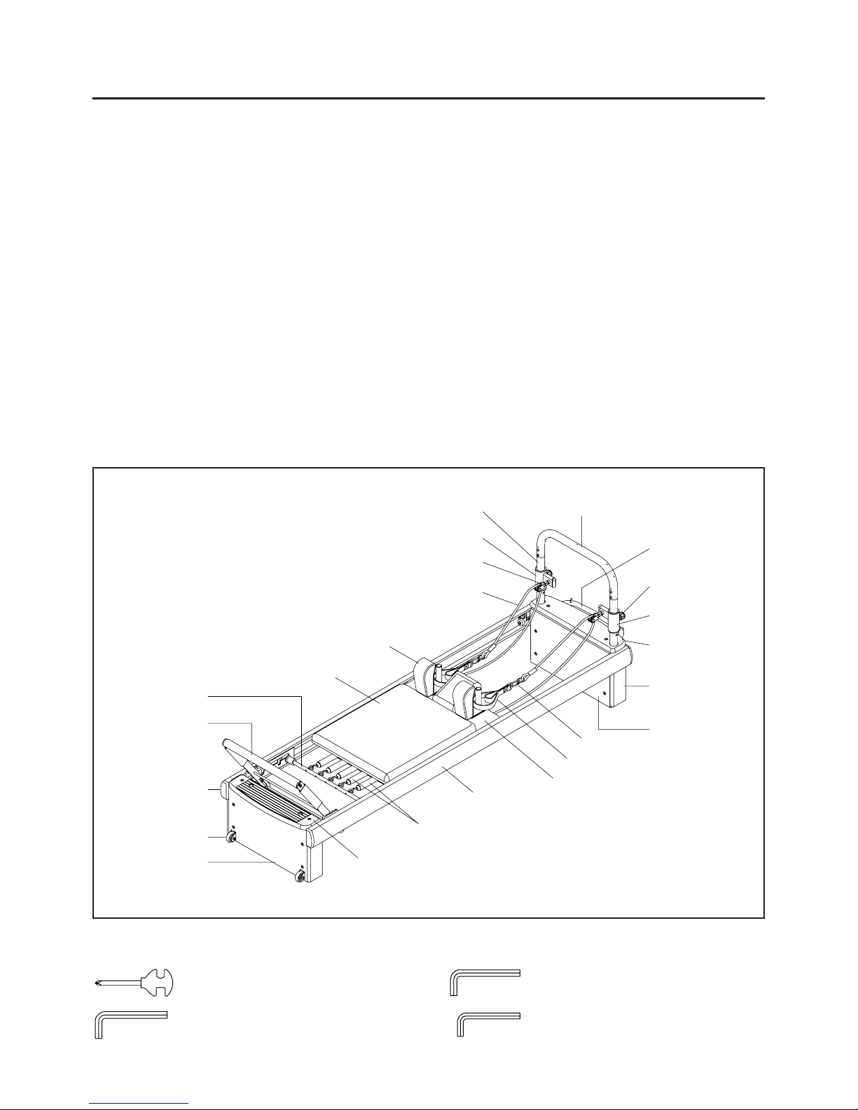
Before reading further , ple ase review the drawing
below and familiarize yourself with the parts that are
labeled.
Read this manual carefully before using the
AeroPilates PRO XP686.
Left Rail
Link
Handlebar
Top Beam
Left Pulley
Slider
Hand Strap
Right Pulley Slider
Rear Wooden
Board
Rear Wooden
Cover
Spring Pin
Pulley Set
Front Wooden
Cover
Cushion Board
Footbar
Cushion
4
Right Rail
Cap
Shoulder Pad
Upright Tube
Spring Bar
Wheel
Rope
Tension Springs
Front Wooden
Platform
Rear Wooden
Platform
THE FOLLOWING TOOLS ARE INCLUDED FOR ASSEMBLY :
Allen Wrench (5mm)
Allen Wrench (4mm)
Combination Wrench
Allen Wrench (6mm)
Although Stamin a tries to manufa cture its products
with the finest materials and uses the highest
standards of manufa cturing, occasionally a part that
does not fit, is the incorrect size, or is otherwise
inappropriate is found. Even with the highest
inspection and quality controls in place, these things
will happen occasionally. Please do not return the
product. Contact us FIRST!
If a part is missing or defective, please call us toll
free at 1-800-375-7520 (in the U.S.). Our Customer
Service Staff is available to a ssist you from 7:30 A.M.
to 5:00 P .M. (Central T ime) Monday through Thursday
and 8:00 A.M. to 3:00 P.M. (Central T i me) on Friday.
If you would like to contact us on-line, go to our
website at www .stamin aproducts.com a nd a ccess the
Customer Service section.
Be sure to have the name and model number of
the product available when you contact us.
5
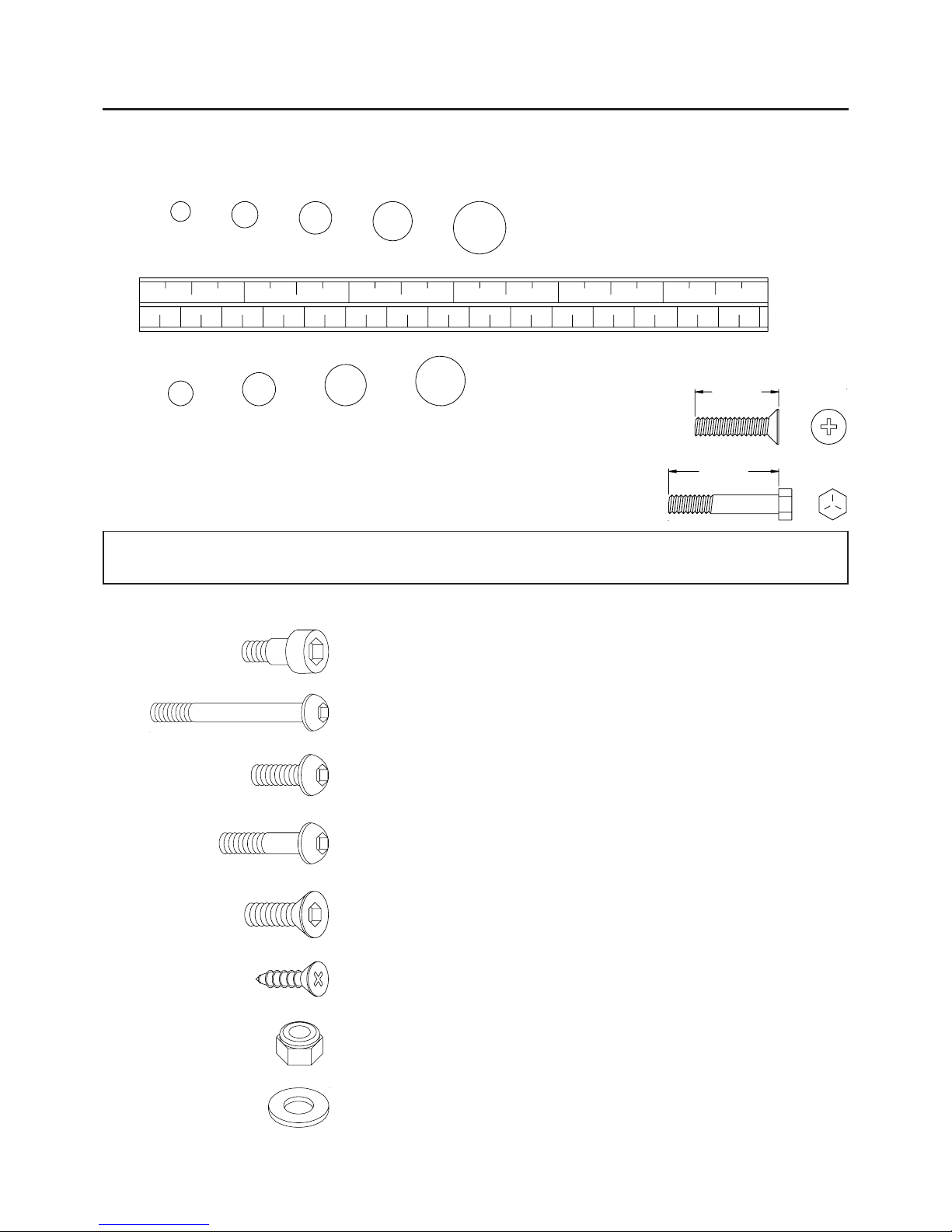
Part No. and Description Qty
87 Bolt, Button Head (M8 x 1.25 x 30mm) 4
88 Bolt, Button Head (M8 x 1.25 x 35mm) 8
89 Bolt, Button Head (M8 x 1.25 x 42mm) 2
99 Screw , Flat Head (M4.5 x 15mm) 8
93 Bolt, Flat Head (M6 x 1 x 15mm) 2
94 Bolt, Flat Head (M8 x 1.25 x 15mm) 2
103 Nylock Nut (M8 x 1.25) 4
104 Washer (M8) 4
24 Pivot Bolt 2
HARDWARE IDENTIFICATION CHART
This chart is provided to help identify the hardware used in the assembly process. Place the washers, the
end of the bolts, or screws on the circles to check for the corre ct diameter. Use the small scale to check the
length of the bolts and screws.
NOTICE: The bolt length is measured from the bottom of the head of the
bolt to the end of the bolt. The head of the bolt is not included in
the measurement unless the it is a flat hea d screw or bolt.
mm.
in.
INCHES
MILLIMETERS
11/2021/2 31/2 41/2 51/2 61/2
0 10 20 30 40 50 60 70 80 90 100 110 120 130 140 150
6 8 10 12
3/16" 5/16" 1/2"3/8"1/4"
length
length
After unpacking the unit, open the hardware bag and make sure that you have all the following items.
Some hardware may be already attached to the part.
84 Bolt, Button Head (M6 x 1 x 82mm) 6
85 Bolt, Button Head (M8 x 1.25 x 15mm) 24
86 Bolt, Button Head (M8 x 1.25 x 25mm) 16
STEP 1
There are three different levels of TENSION SPRINGS, high TENSION SPRING, RED MARKED(66),
medium TENSION SPRING, YELLOW MARKED(67), a nd low TENSION SPRING, BLUE MARKED(68).
Place the CARRIAGE ASSEMBLY upside down on the floor. Hook the ends of the TENSION SPRINGS
without color marks into the positions shown in the illustration. The blue marked springs are in the outside
positions, the red marked spring is in the center position, and the yellow marked springs are between the
red and blue springs.
HINT:
ASSEMBLY INSTRUCTIONS
Place all parts from the box in a cleared area and position them on the floor in front of you. Remove all
packing materi als from your area a nd pla ce them ba ck into the box. Do not dispose of the pa cking materials
until assembly is completed. Read each step carefully before beginning. If you are missing a part please
call our toll-free number for assistance 1 (800) 375-7520 or e-mail us at :
parts@staminaproducts.com
6
(68)Tension Spring,
blue marked
(67)Tension Spring,
yellow marked
(66)Tension Spring, red marked
(68)Tension Spring,
blue marked
(67)Tension Spring,
yellow marked
Tension
Spring
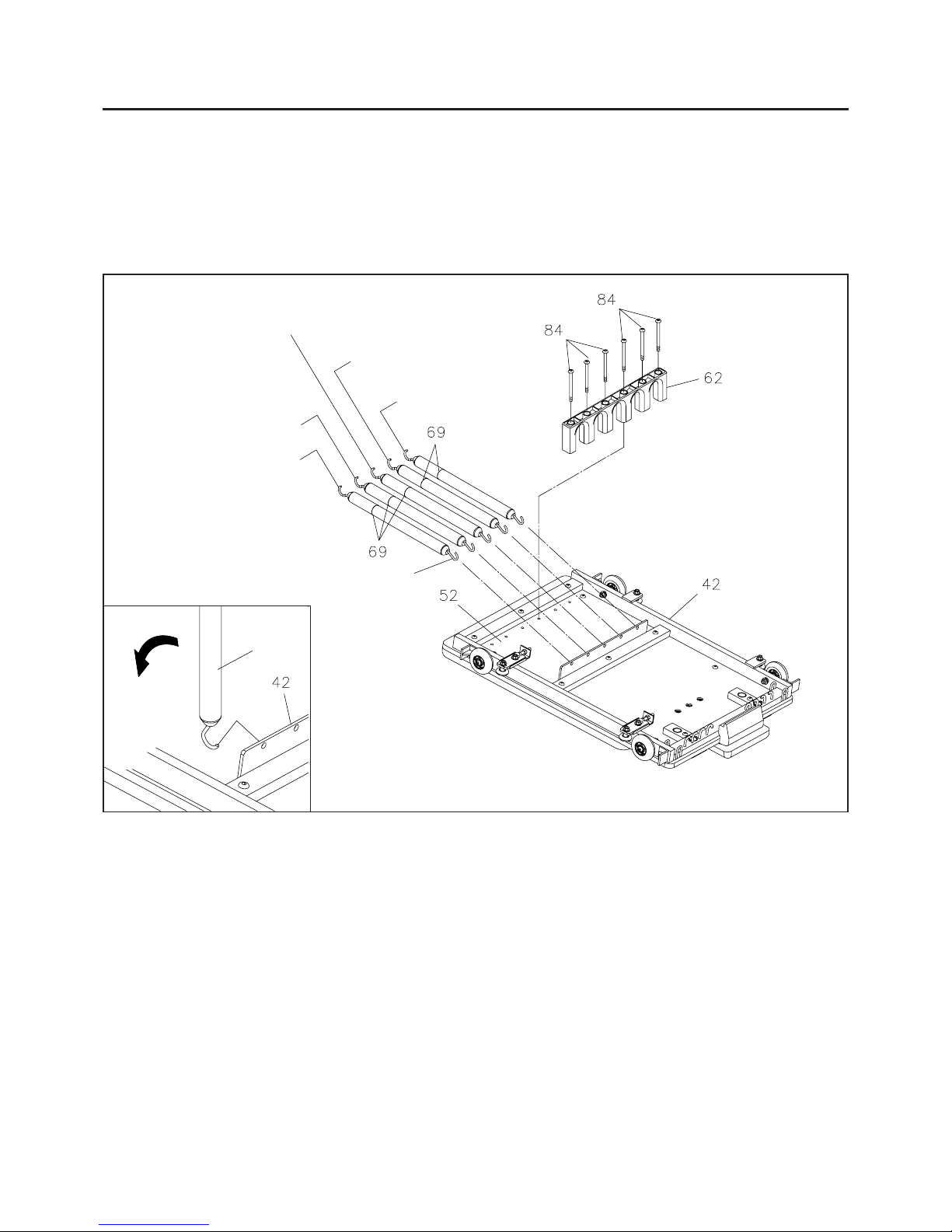
Refer to the inset drawing. Hold the spring in a vertical position and hook it onto the plate on the
CARRIAGE FRAME(42) as shown.
Make sure that the spring is hooked in the direction shown in the inset drawing.
1.
2.
STEP 2
NOTE:
End without color mark
Attach the SPRING HOLDER(62) onto the CUSHION BOARD(52) with BUTTON HEAD BOLTS
(M6x1x82mm)(84).
There are SPRING SLEEVES(69) on the SPRINGS. Make sure the SPRING SLEEVES(69) cover
on the SPRINGS smoothly and stay between the SPRINGS and SPRING HOLDER(62).
ASSEMBLY INSTRUCTIONS
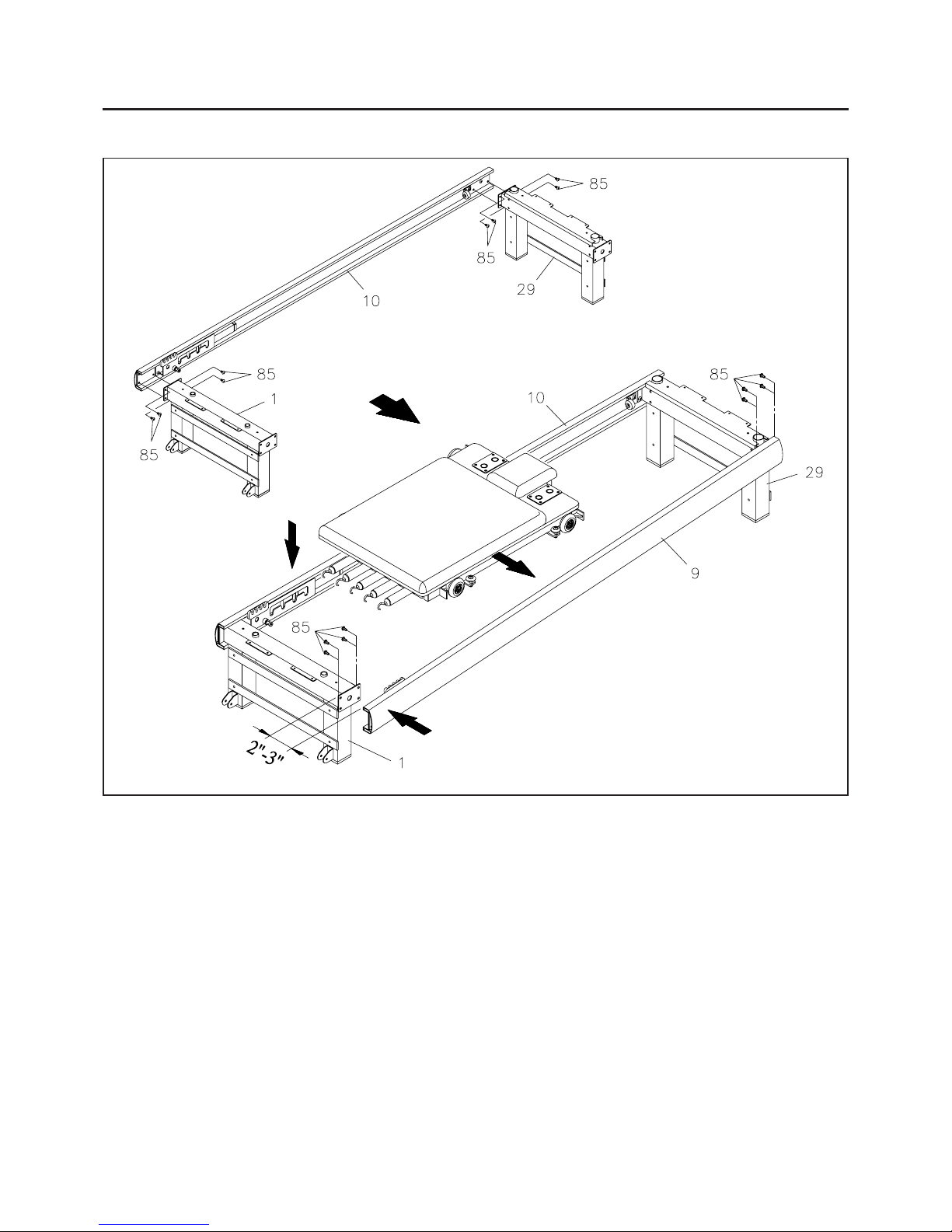
STEP 3: Attach the RIGHT RAIL(10) onto the FRONT FRAME(1) and REAR FRAME(29) with BUTTON
HEAD BOLTS(M8x1.25x15mm)(85).
HINT:
LEFT
RIGHT
1
Screw the Bolts half way
into the LEFT RAIL(9).
2
Keep the gap
2 to 3 inches.
3
Slide this side of the
CARRIAGE ASSEMBL Y
into the LEFT RAIL(9)
4
Slide this side of the
CARRIAGE ASSEMBL Y
into the RIGHT RAIL(10)
5
Push this end of the LEFT RAIL(9)
onto the FRONT FRAME(1) and
secure with the Bolts.
Study the illustration carefully to make sure that the FRONT FRAME(1) a nd REAR FRAME(29) are
not reversed. The FRONT FRAME(1) has brackets for the WHEELS(8) near the bottom and small
holes on the top surface. M ake sure that the RAILS(9, 10) are not upside down. M ake sure that the
LEFT RAIL(9) and RIGHT RAIL(10) are not reversed.
7
a.
b.
c.
Have your a ssistant hold the front end of the LEFT RAIL(9). Attach the back end of the LEFT RAIL(9)
onto the REAR FRAME(29) with BUTTON HEAD BOLTS(M8x1.25x15mm)(85). Screw the BOLTS
half way into the LEFT RAIL(9).
Keep the gap between front end of the LEFT RAIL(9) and the FRONT FRAME(1) about 2 to 3 inches.
Then lift up the CARRIAGE ASSEMBL Y and slide it into the RAILS as shown in the illustration.
Push the front end of the LEFT RAIL(9) onto the FRONT FRAME(1) and secure with BUTTON HEAD
BOLTS(M8x1.25x15mm)(85). Tighten all the BOLTS.
STEP 4: IT IS NECESSARY TO OBTAIN ASSISTANCE FROM ANOTHER PERSON FOR ASSEMBLY.
Use the following procedure to assemble the LEFT RAIL(9) and CARRIAGE ASSEMBL Y :
NOTE: Review sequence 1 through 5 in the illustration above before beginning this procedure.
 Loading...