

Stamina A150-104 Owner's Manual
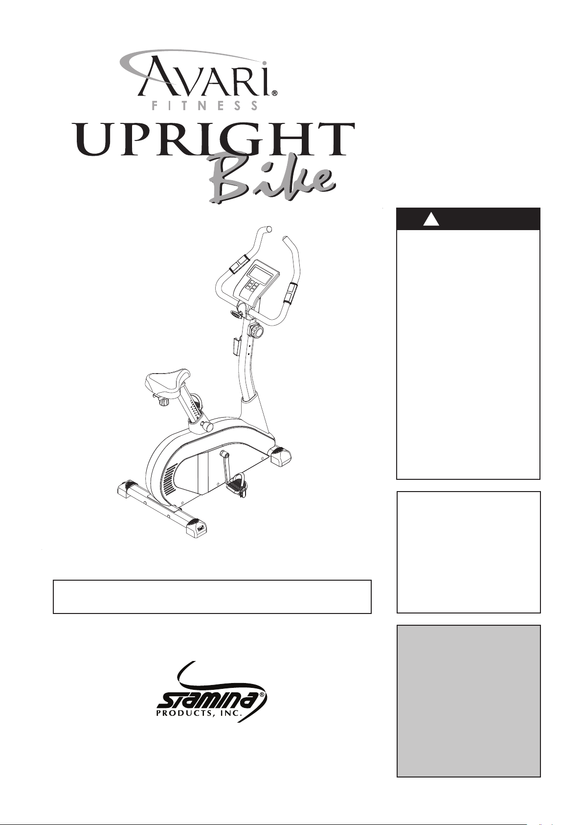
2000C
Owner's
Manual
!
WARNING
Exercise can present a
h e a l th r i sk . Co n su l t a
physician before beginning
any exercise program with
this equipment. If you feel
faint or dizzy, immediately
dis c o n t i nue use of this
equipment. Serious bodily
in j u ry c a n occ u r if th is
equipment is not assembled
and used correctly. Serious
bodily injury can also occur
if all in str uct ion s a re not
followed. Keep others and
pets away from equipment
when in use. Always make
sure all bolts and nuts are
securely tightened prior to
each use. Follow all safety
instructions in this manual.
Product May Vary Slightly From Pictured.
CAUTION:
Weight on this product should not exceed 250 lbs.
This Product is Distributed Exclusively by
2040 N. Alliance, Springeld, MO 65803
Customer Service
1 (800) 375-7520
www.staminaproducts.com
When calling for parts or
service, please specify
the following number
:
Model#: A150-104
STAMINA PRODUCTS
MADE IN CHINA
2012 Stamina Products, Inc.
©
2012, 12

TABLE OF CONTENTS
Safety Instructions ...................................... 2
Before You Begin ........................................ 4
Equipment Warning, Caution & Notice Labels ... 5
Hardware Identication Chart .................... 6
Assembly Instructions ................................ 7
Set Up Instructions ................................... 12
Operational Instructions ........................... 13
Storage ....................................................... 20
Conditioning Guidelines ........................... 21
Warm-Up and Cool-Down ......................... 22
Warranty ..................................................... 23
Product Parts Drawing .............................. 24
Parts List .................................................... 25
Fax/Mail Ordering Form ............................ 27
Maintenance ............................................... 20
SAFETY INSTRUCTIONS
!
WARNING
!
CAUTION
!
WARNING
1. Read all warnings and cautions posted on the AVARI® 2000C Upright Bike.
2. The AVARI® 2000C Upright Bike should only be used after a thorough review of the Owner’s Manual.
sure that it is properly assembled and tightened before use.
3. We recommend that two people be available for assembly of this product.
4. Keep children away from the AVARI® 2000C Upright Bike. Do not allow children to use or play on the
AVARI® 2000C Upright Bike. Keep children and pets away from the AVARI® 2000C Upright Bike when it
is in use.
5. Remain seated while pedaling the
injury.
6. It is recommended that you place this exercise equipment on an equipment mat.
7. Set up and operate the AVARI® 2000C Upright Bike on a solid level surface. Do not position the AVARI®
2000C Upright Bike on loose rugs or uneven surfaces.
8. Make sure that adequate space is available for access to and around the AVARI® 2000C Upright Bike.
9. Adjust the ADJUSTABLE ENDCAPS(35) on the REAR STABILIZER(2) so that the AVARI® 2000C Upright
Bike sits on the oor without rocking.
10. Before using, inspect the AVARI® 2000C Upright Bike for worn or loose components, and securely tighten
or replace any worn or loose components prior to use.
11. Before getting on the
and HANDLEBAR(4) to be sure they are secure. The ADJUSTMENT KNOB(44) must be inserted into one
of the holes in the SEAT POST(5) and securely tightened.
12. Each user should adjust the seat per instructions on page 13 and page 14.
13. Do not attempt to adjust the seat while you are on the AVARI® 2000C Upright Bike.
14. Consult a physician prior to commencing an exercise program and follow his/her recommendations in
developing your tness program. If at any time during exercise you feel faint, dizzy, or experience pain, stop
and consult your physician.
15. Always choose the workout which best ts your physical strength and exibility level. Know your limits and
train within them. Always use common sense when exercising.
16. Do not wear loose or dangling clothing while using the AVARI® 2000C Upright Bike.
17. Never exercise in bare feet or socks; always wear proper footwear such as running, walking, or cross training
shoes that t well, provide foot support, and feature non-skid rubber soles.
18. Be careful to maintain your balance while using, mounting, dismounting, or assembling the AVARI® 2000C
Upright Bike, loss of balance may result in a fall and serious bodily injury.
19. The AVARI® 2000C Upright Bike should not be used by persons weighing over 250 pounds.
20. The AVARI® 2000C Upright Bike should be used by only one person at a time.
21. Use two people to move the AVARI® 2000C Upright Bike.
22. The AVARI® 2000C Upright Bike is for consumer use only. It is not for use in public or semipublic facilities.
This product contains a chemical known to the State of California to cause
cancer and birth defects or other reproductive harm.
Consult your physician before starting this or any exercise program. This is
especially important if you are over the age of 35, have never exercised before,
are pregnant, or suffer from any health problem. This product is for home use
only. Do not use in institutional or commercial applications. Failure to follow all
warnings and instructions could result in bodily injury and property damage.
To reduce the risk of serious injury, read the following Safety Instructions
before using the
AVARI® 2000C Upright Bike
AVARI® 2000C Upright Bike
AVARI® 2000C Upright Bike
, always check the SEAT POST(5), PEDALS(10, 70),
2
.
Make
. Failure to do so could result in serious

Call Us First
www.staminaproducts.com
1 (800) 375-7520
Customer Service
THANK YOU FOR PURCHASING THE
AVARI® 2000C Upright Bike
To enact your warranty, please register your product
by going to register.staminaproducts.com
To help you get started, we have pre-assembled most of your
AVARI® 2000C Upright Bike at the factory with the exception
of those few parts left unassembled for shipping purposes.
Simply follow the few assembly instructions set forth in this manual.
With regular workouts, you will be getting your body into shape
and be on your way to achieving a happier and healthier lifestyle.
Should you have any questions,
please call our Customer Service Department toll-free number,
Monday - Thursday, 7:30 A.M. - 5:00 P.M., Central Time.
Friday, 8:00 A.M. - 3:00 P.M., Central Time.
1 (800) 375-7520
ONLINE
CUSTOMER SERVICE
customerservice@staminaproducts.com
www.staminaproducts.com
TELEPHONE
CUSTOMER SERVICE
Tel: 1 (800) 375-7520
3
FAX
CUSTOMER SERVICE
Fax: (417) 889-8064
MAIL
STAMINA PRODUCTS, INC.
ATTN: Customer Service
P.O. Box 1071
Springeld, MO. 65801-1071
BEFORE YOU BEGIN
Thank you for choosing the AVARI® 2000C
Upright Bike. We take great pride in producing
this quality product and hope it will provide many
hours of quality exercise to make you feel better,
look better, and enjoy life to its fullest.
It's a proven fact that a regular exercise program
can improve your physical and mental health.
Too often, our busy lifestyles limit our time and
opp ortun ity t o ex ercis e. T he AVAR I® 2 000C
Upright Bike provides a convenient and simple
method to begin your assault on getting your body
in shape and achieving a happier and healthier
lifestyle.
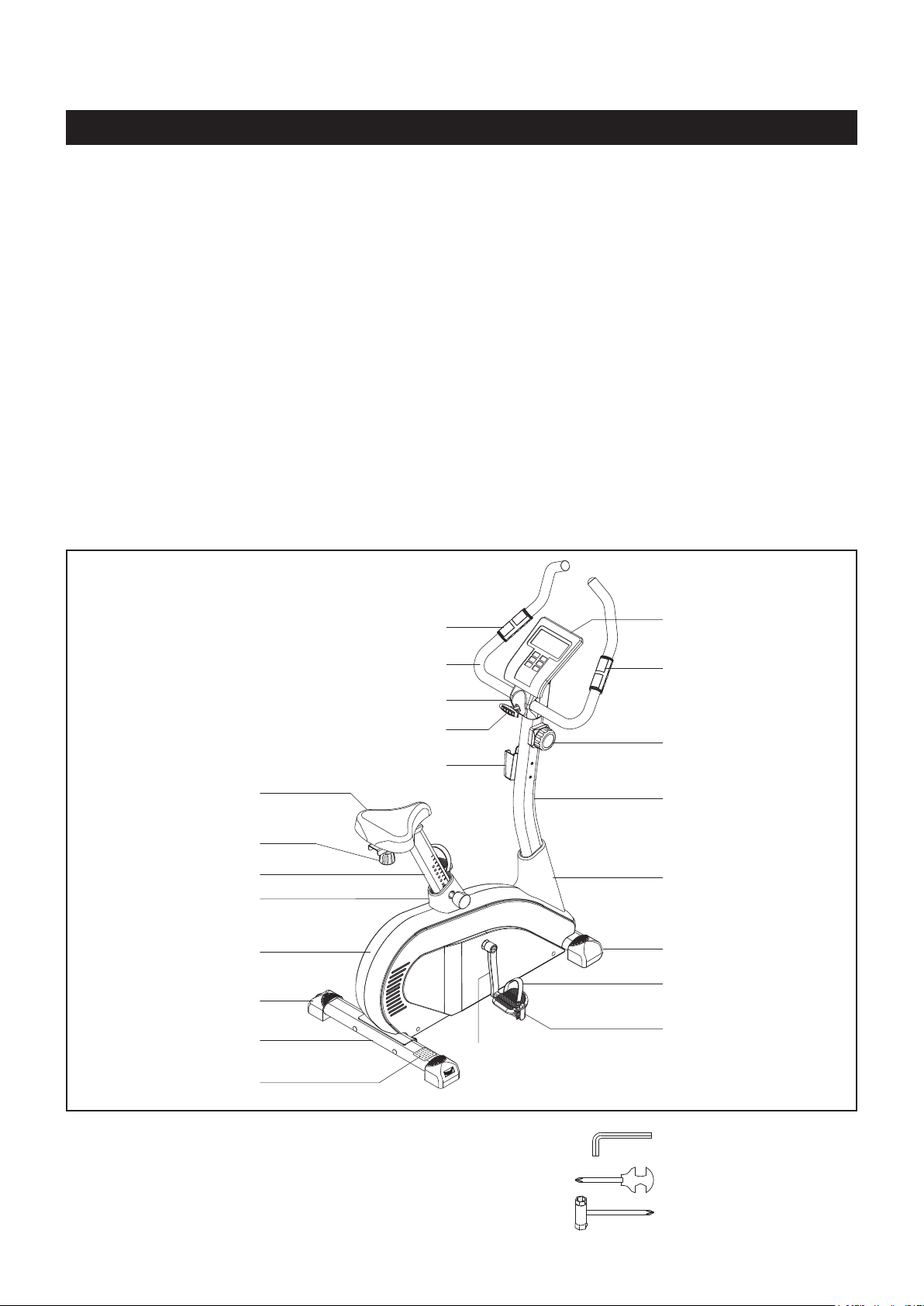
Before r e ading fu r t h er, p lease rev i e w the
drawing below and familiarize yourself with the
parts that are labeled.
Read this manual carefully before using the
AVARI® 2000C Upright Bike.
Pulse Sensor Plate
Although Stamina constructs its products with
the nest materials and uses the highest standards
of manufacturing and quality control, there can
sometimes be missing parts or incorrectly sized
parts. If you have any questions or pro ble ms
with the parts included with your AVARI® 2000C
Upright Bike, please do not return the product.
Contact us FIRST!
If a part is missing or defective, please go to
staminaproducts.com to the Services section and
order the part needed, or call us toll free at 1-800375-7520 (in the U.S.). Our Customer Service Staff
is available to assist you from 7:30 A.M. to 5:00 P.M.
(Central Time) Monday through Thursday and 8:00
A.M. to 3:00 P.M. (Central Time) on Friday.
Be sure to have the name and model number of
the product available when you contact us.
Meter
Seat
Locking Knob
Seat Post
Post Sleeve
Left Cover
Adjustable Cap
Rear Stabilizer
Caution Label
Handlebar
Handlebar Cover
T Knob
Tray
Pulse Sensor Plate
Tension Knob
Upright
Upright Sleeve
Right Endcap
Right Pedal Strap
Right Pedal
Right Crank
THE FOLLOWING TOOLS ARE INCLUDED FOR ASSEMBLY :
4
Allen Wrench (5mm)
Combination Wrench
Socket Wrench
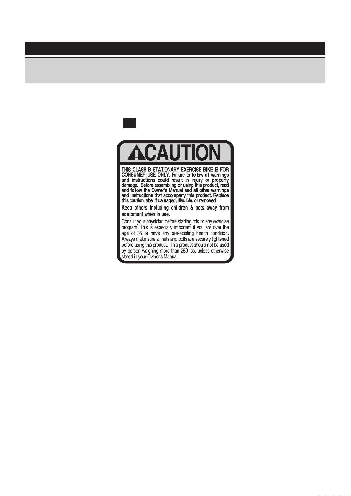
EQUIPMENT WARNING, CAUTION & NOTICE LABELS
This chart is provided to help identify the warning, caution, and notice labels on the AVARI® 2000C
Upright Bike. Please take a moment to familiarize yourself with all of the warning, caution, and
notice labels.
Label is larger than actual size
CAUTION LABEL(74)C1
5
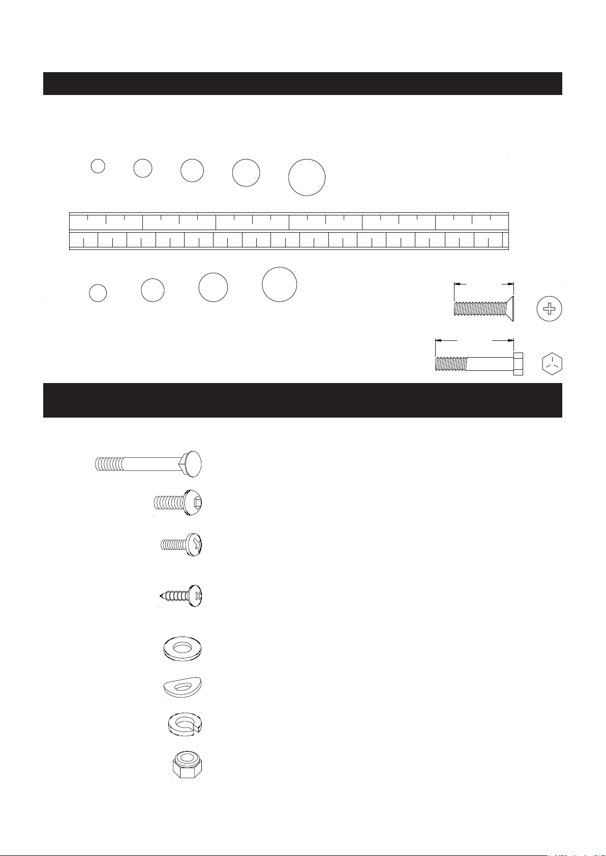
HARDWARE IDENTIFICATION CHART
This chart is provided to help identify the hardware used in the assembly process. Place the washers or
the ends of the bolts or screws on the circles to check for the correct diameter. Use the small scale to
check the length of the bolts and screws.
3/16" 1/4" 5/16" 3/8" 1/2"
INCHES
0 1/2 1 1/2 2 1/2 3 1/2 4 1/2 5 1/2 6
0 10 20 30 40 50 60 70 80 90 100 110 120 130 140 150
MILLIMETERS
6 8 10 12
NOTICE: The length of all bolts and screws, except those with flat
heads, is measured from below the head to the end of the bolt
or screw. Flat head bolts and screws are measured from the
top of the head to the end of the bolt or screw.
After unpacking the unit, open the hardware bag and make sure that you have all the following items.
Some hardware may be already attached to the part.
length
length
in.
mm.
Part No. and Description Qty
47 Carriage Bolt (M10 x 1.5 x 94mm) 2
49 Bolt, Button Head (M8 x 1.25 x 20mm) 4
50 Screw, Round Head (M5 x 0.8 x 16mm) 1
51 Screw, Round Head (M5 x 0.8 x 10mm) 4
52 Screw, Round Head (M4 x 0.7 x 25mm) 1
53 Screw, Round Head (M4 x 30mm) 2
54 Screw, Round Head (M4 x 20mm) 2
57 Screw, SMALL Round Head (M4 x 20mm) 2
60 Washer (M4) 1
61 Small Washer (M8) 1
63 Washer (M8) 2
65 Arc Washer (M8) 2
72 Arc Washer (M10) 2
66 Lock Washer (M8) 5
73 Lock Washer (M10) 2
67 Nylock Nut (M10 x 1.5) 2
6
ASSEMBLY INSTRUCTIONS
Place all parts from the box in a cleared area and position them on the oor in front of you. Remove
all packing materials from your area and place them back into the box. Do not dispose of the packing
materials until assembly is completed. Read each step carefully before beginning. If you are missing
a part, please go to staminaproducts.com to the Services section and order the part needed, e-mail
us at customerservice@staminaproducts.com, or call us toll free at 1-800-375-7520 (in the U.S.). Our
Customer Service Staff is available to assist you from 7:30 A.M. to 5:00 P.M. (Central Time) Monday
through Thursday and 8:00 A.M. to 3:00 P.M. (Central Time) on Friday.
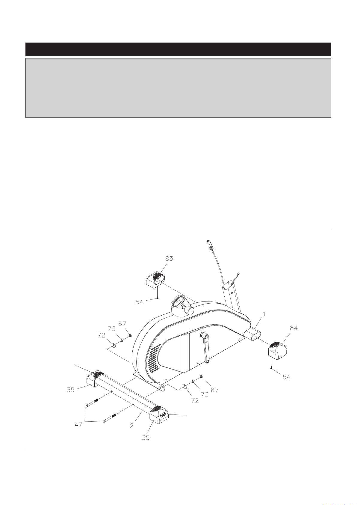
STEP 1
Press the LEFT and RIGHT ENDCAPS(83, 84) on to the front stabilizer of the MAIN FRAME(1) and secure
with ROUND HEAD SCREWS(M4x20mm)(54).
STEP 2
Attach the REAR STABILIZER(2) to the MAIN FRAME(1) with CARRIAGE BOLTS(M10x1.5x94mm)(47),
ARC WASHERS(M10)(72), LOCK WASHERS(M10)(73), and NYLOCK NUTS(M10x1.5)(67).
NOTE: You can turn the dials in the ADJUSTABLE ENDCAPS(35) which are attached to the REAR
STABILIZER(2) to keep the bike stable.
Dial
Dial
7
ASSEMBLY INSTRUCTIONS
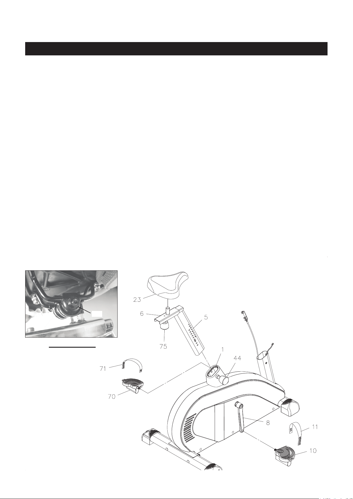
STEP 3
NOTE: The RIGHT PEDAL(10) has R stamped on the end of the pedal shaft. The RIGHT PEDAL(10) has
right hand threads and is tightened by turning clockwise. The LEFT PEDAL(70) has L stamped on
the end of the pedal shaft. The LEFT PEDAL(70) has left hand threads and is tightened by turning
counterclockwise.
Thread the RIGHT PEDAL(10) into the RIGHT CRANK(8) as shown. Tighten the pedal securely. Select
the RIGHT PEDAL STRAP(11) which has R marked on it. Snap the three hole end to the inside edge of
the RIGHT PEDAL(10). Insert the other end of the strap through the slot and snap the strap to the hook
on the outside edge of the RIGHT PEDAL(10). Select adjustment holes which allow your foot to be easily
removed from the pedals.
Use the same procedure to attach the LEFT PEDAL(70) to the LEFT CRANK(9) and to attach the LEFT
PEDAL STRAP(71) to the LEFT PEDAL(70).
STEP 4: Refer to the Bottom View below. Attach the SEAT(23) to the SEAT SLIDER(6) by inserting the
connector of the SEAT SLIDER(6) into the SEAT(23) and lock in position by tightening the NUT(M8x1.25).
Pull the ADJUSTMENT KNOB(44), then insert the SEAT POST(5) into the MAIN FRAME(1) and secure
with the ADJUSTMENT KNOB(44).
NOTE: The pin of the ADJUSTMENT KNOB(44) must be inserted into one of the adjustment holes in the
SEAT POST(5) and the ADJUSTMENT KNOB(44) must be screwed in tight to ensure that the
SEAT POST(5) will t securely in the MAIN FRAME(1).
With the SEAT(23) attached to the SEAT SLIDER(6), and the SEAT POST(5) attached securely to the MAIN
FRAME(1), adjust the SEAT(23) to a level position. Loosen the NUTS(M8x1.25) under the SEAT(23), and
raise or lower the front of the SEAT(23) until the top of the SEAT(23) is parallel to the oor. Make sure that
the seat points straight forward and securely re-tighten the NUTS(M8x1.25).
Nut
Bottom View
8
ASSEMBLY INSTRUCTIONS
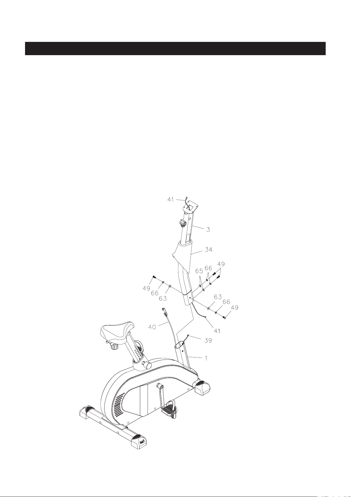
STEP 5
Slide the UPRIGHT SLEEVE(34) over the UPRIGHT(3). Insert the TENSION CABLE(40) through the
UPRIGHT(3) until the TENSION CABLE(40) is through and extends out of the square opening in the
side of the UPRIGHT(3). Connect the CONNECTION WIRE(41) to the SENSOR WIRE(39). Insert the
UPRIGHT(3) into the MAIN FRAME(1) and secure with BUTTON HEAD BOLTS(M8x1.25x20mm)(49),
LOCK WASHERS(M8)(66), WASHERS(M8)(63), and ARC WASHERS(M8)(65). Slide down the UPRIGHT
SLEEVE(34) to cover the bolt heads.
9
 Loading...