

Page 1
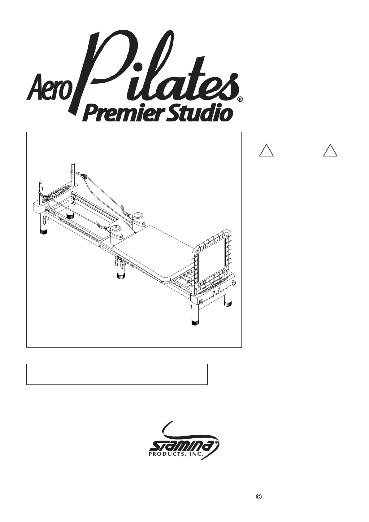
Owner's
Manual
! WARNING !
Exercise can pre sent a health
risk. Consult a physician
before beginning a ny exercise
program with this equipment.
If you feel faint or dizzy,
immediately discontinue use
of this equipment. Serious
bodily injury can occur if this
equipment is not assembled
and used correctly. Serious
bodily injury can also occur if
all instructions are not
followed. Keep others and
pets away from equipment
when in use. Always make
sure all bolts and nuts are
tightened prior to each use.
Follow all safety instructions in
this manual.
CAUTION:
We ight on this product should not exceed 300 lbs.
This Product is Produced Exclusively by
2040 N. Alliance, Springf ield, MO 65803
Customer Service Number
1 (800) 375-7520
2007, 12
www.stamin aproducts.com
When calling for parts or
service, please specify the
following number.
55-4700
Pat. No. D382,319
Other Patents Applied
and Are Pending
MADE IN CHINA
Product May Vary Slightly
From Pictured.
2007 Stamina Products, Inc.
Page 2
TABLE OF CONTENTS
Page Page
Safety Instructions 2
Before Y ou Begin 4
Equipment Warning & Notice Labels 5
Hardware Identification Chart 6
Assembly In struction s 7
Operational Instructions 11
Storage 12
Maintenance 12
Conditioning Guidelines 13
Warm-Up a nd Cool-Down 14
Warranty 15
Product Parts Drawing 16
Parts List 17
Fax/Mail Ordering Form 19
SAFETY INSTRUCTIONS
WARNING:
We recommend that two people be available for assembly of this product.
1.
Read all warnings posted on the AeroPilates
2.
Read this Owner's Manual and follow it carefully before using the AeroPilates Premier Studio.
3.
Make sure that it is properly assembled and tightened before use.
Make sure that all e ight (8) pull pins are fully inserted before using the AeroPilates
4.
5.
When exercising on this product, do not exercise at an intensity that causes the product itself to
move. This could result in damage to your joints and the product.
6.
Keep children away from the AeroPilates
the AeroPilates Premier Studio. Keep children and pets away from the AeroPilates Premier
Studio when it is in use.
7.
It is recommended that you pla ce this exercise equipment on an equipment mat.
8.
Set up and operate the AeroPilates
AeroPilates
9.
Make sure that adequate space is available for access to and around the AeroPilates Premier
Studio.
10.
Inspect the AeroPilates
11.
Tighten/replace a ny loose or worn components prior to using the AeroPilates
12.
Consult a physician prior to commencing an exercise program. If, at any time during exercise, you
feel faint, dizzy, or experience pain, stop and consult your physician.
13.
Follow your physicia n's recommendations in developing your own personal fitness program.
14.
Always choose the workout which best fits your physical strength and flexibility level. Know your
limits and train within them. Always use common sense when exercising.
15.
Do not wear loose or dangling clothing while using the AeroPilates
16.
Be careful to maintain your balance while using, mounting, dismounting, or assembling the
AeroPilates
17.
The AeroPilates Premier Studio should not be used by persons weighing over 300 pounds.
18.
The AeroPilates
19.
The AeroPilates
facilities.
To reduce the risk of serious injury, read the following Safety Instructions before
using the AeroPilates
Premier Studio on loose rugs or uneven surfaces.
Premier Studio for worn or loose components prior to use.
Premier Studio, loss of bala nce may result in a fall and serious bodily injury.
Premier Studio should be used by only one person at a time.
Premier Studio is for con sumer use only . It is not f or use in public or semipublic
Premier Studio.
Premier Studio.
Premier Studio.
Premier Studio. Do not allow children to use or play on
Premier Studio on a solid level surface. Do not position the
Premier Studio.
Premier Studio.
WARNING:
Before starting any exercise or conditioning program you should consult with your personal
physicia n to see if you require a complete physical exa m. This is especially i mporta nt if you
are over the age of 35, have never exercised before, are pregnant, or suffer from any
illness. READ AND FOLLOW THE SAFETY PRECAUTIONS. FAILURE TO FOLLOW
THESE INSTRUCTIONS CAN RESUL T IN SERIOUS BODILY INJURY.
2
Page 3

CALL US FIRST
THANK YOU FOR PURCHASING THE
AeroPilates
To help you get started, we have pre-assembled most of your
AeroPilates Premier Studio at the factory with the exception
of those few parts left unassembled f or shipping purposes.
Simply follow the few assembly instructions set forth in this manual.
With regular workouts you will be getting your body into shape
and on your way to achieving a happier and healthier lifestyle.
Should you have any questions,
please call our Customer Service Department toll-free number,
1 (800) 375-7520
Monday - Thursday, 7:30 A.M. - 5:00 P.M. Central Time.
Friday, 8:00 A.M. - 3:00 P.M., Central Time.
Premier Studio
TELEPHONE
CUSTOMER SERVICE
Tel: 1 (800) 375-7520
FAX
CUSTOMER SERVICE
Fax: (417) 889-8064
ONLINE
CUSTOMER SERVICE
www.staminaproducts.com
3
STAMINA PRODUCTS, INC.
MAIL
ATTN: Customer Service
P.O. Box 1071
Springfield, MO. 65801-1071
Page 4
BEFORE YOU BEGIN
Thank you f or choosing the AeroPilates Premier
Studio. We take great pride in producing this quality
product and hope it will provide ma ny hours of quality
exercise to make you feel better , look better and enjoy
life to its fullest.
Yes, it's a proven fact that a regular exercise
program can improve your physical and mental
health. Too often, our busy lifestyles limit our time
and opportunity to exercise. The AeroPilates
Premier Studio provides a convenient and simple
method to begin your a ssault on getting your body in
sha pe and a chieving a happier a nd healthier lifestyle.
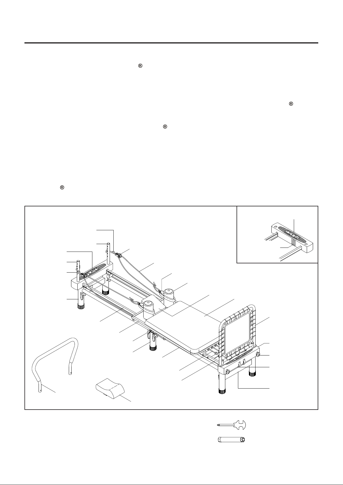
Before reading further, please review the drawing
below and familiarize yoursel f with the parts that are
labeled.
Read this manual carefully before using the
AeroPilates
Left Pulley Hook
Premier Studio.
Although Stamin a constructs its products with the
finest materials and uses the highest standards of
manufacturing and quality control, there can
sometimes be missing parts or incorrectly sized
parts. If you have any questions or problems with
the parts included with your AeroPilates
Studio, please do not return the product. Contact
us FIRST!
If a part is missing or defective, please call us toll
free at 1-800-375-7520 (in the U.S.). Our Customer
Service Staff is available to a ssist you from 7:30 A.M.
to 5:00 P .M. (Central T ime) Monday through Thursday
and 8:00 A.M. to 3:00 P.M. (Central T i me) on Friday.
If you would like to contact us online, go to our
website at www.sta min aproducts.com a nd a ccess the
Customer Service section.
Be sure to have the name and model number of
the product available when you conta ct us.
Front Cover
Premier
Pulley Riser
Rear Cover
Pulley Riser
Right Pulley
Hook
Rear Sta nd
Footbar
Rear Fra me
Carriage
Middle Stand
Pulley Set
Pull Pin
Connection Bar
Rope
Hand Strap
Tension Cord
Front Frame
Headpa d
Warning
Label
Foam Pad
Headrest
Cushion
Cardio
Rebounder
Front Cover
Locking Knob
Wheel
Front Stand
THE FOLLOWING TOOLS ARE REQUIRED FOR ASSEMBLY : Combination Wrench
Socket Wrench
4
Page 5
EQUIPMENT WARNING & NOTICE LABELS
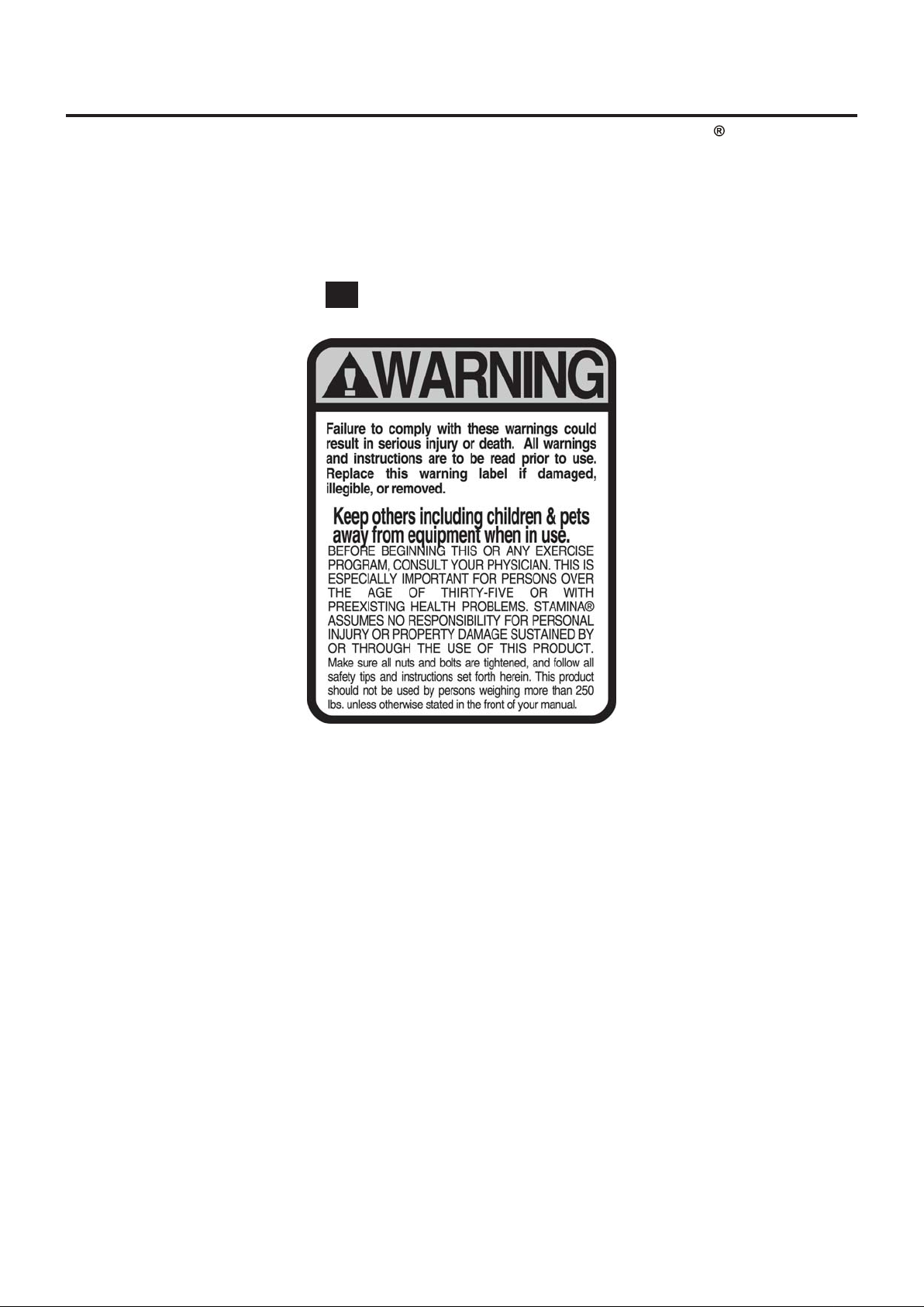
This chart is provided to help identify the warning & notice labels on the AeroPilates Premier Studio.
Please take a moment to familiarize yourself with all of the warning & notice labels.
Label is larger than actual size
W1
WAR NING LABEL(61)
5
Page 6

HARDWARE IDENTIFICATION CHART
This chart is provided to help identify the hardware used in the assembly process. Place the washers, the
end of the bolts, or screws on the circles to check for the corre ct di ameter. Use the small scale to check the
length of the bolts and screws.
3/16" 5/16" 1/2"3/8"1/4"
INCHES
11/2021/2 31/2 41/2 51/2 61/2
0 10 20 30 40 50 60 70 80 90 100 110 120 130 140 150
MILLIMETERS
6 8 10 12
NOTICE: The length of all bolts and screws except those with flat hea ds is
measured from below the head to the end of the bolt or screw.
Flat head bolts and screws are measured from the top of the
head to the end of the bolt or screw.
After unpacking the unit, open the hardware bag and make sure that you have all the following items.
Some hardware may be already attached to the part.
length
length
in.
mm.
Part No. and Description Qty
38 Screw, Round Head (M5 x 0.8 x 25mm) 4
42 Nylock Nut (M8 x 1.25) 2
47 Washer (M8) 6
26 Locking Knob 4
27 Plastic Wheel 2
28 Rubber Foot 4
6
Page 7
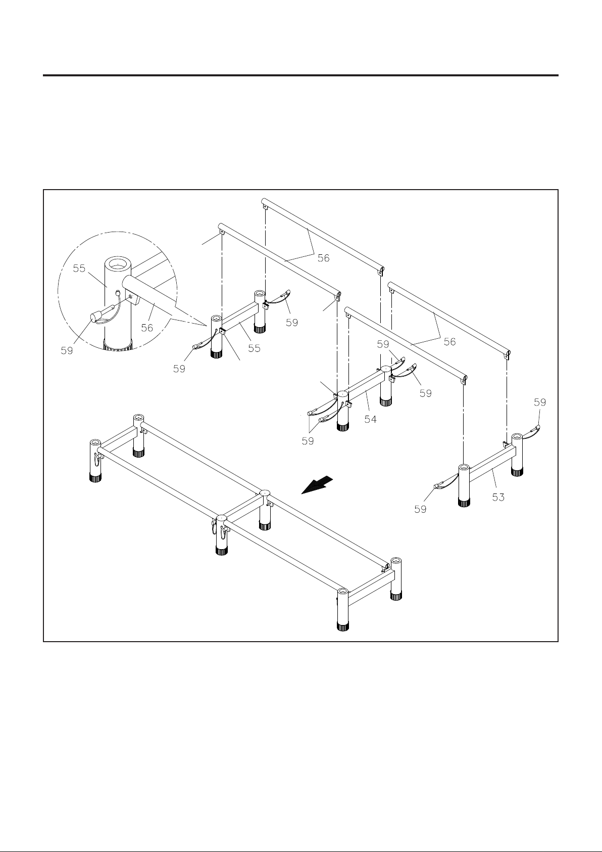
ASSEMBLY INSTRUCTIONS
Place all parts from the box in a cleared area and position them on the floor in front of you. Remove all
packing materi als from your area a nd pla ce them ba ck into the box. Do not dispose of the pa cking materials
until assembly is completed. Read each step carefully before beginning. If you are missing a part please
call our toll-free number for assistance 1 (800) 375-7520 or e-mail us at :
REAR
Fin
Fin
Double
Flanges
Double
Flanges
FRONT
STEP 1
Connect the REAR STAND(55), the narrower one, to the MIDDLE STAND(54) with two CONNECTION
BARS(56), inserting the fins on the CONNECTION BARS(56) into the gaps in the double flanges on the
STANDS(55, 54). Then lock the CONNECTION BARS(56) in the place by inserting the PULL PINS(59)
through the double flanges. Re pe at to connect the FRONT STAND(53) to the MIDDLE STAND(54).
7
Page 8
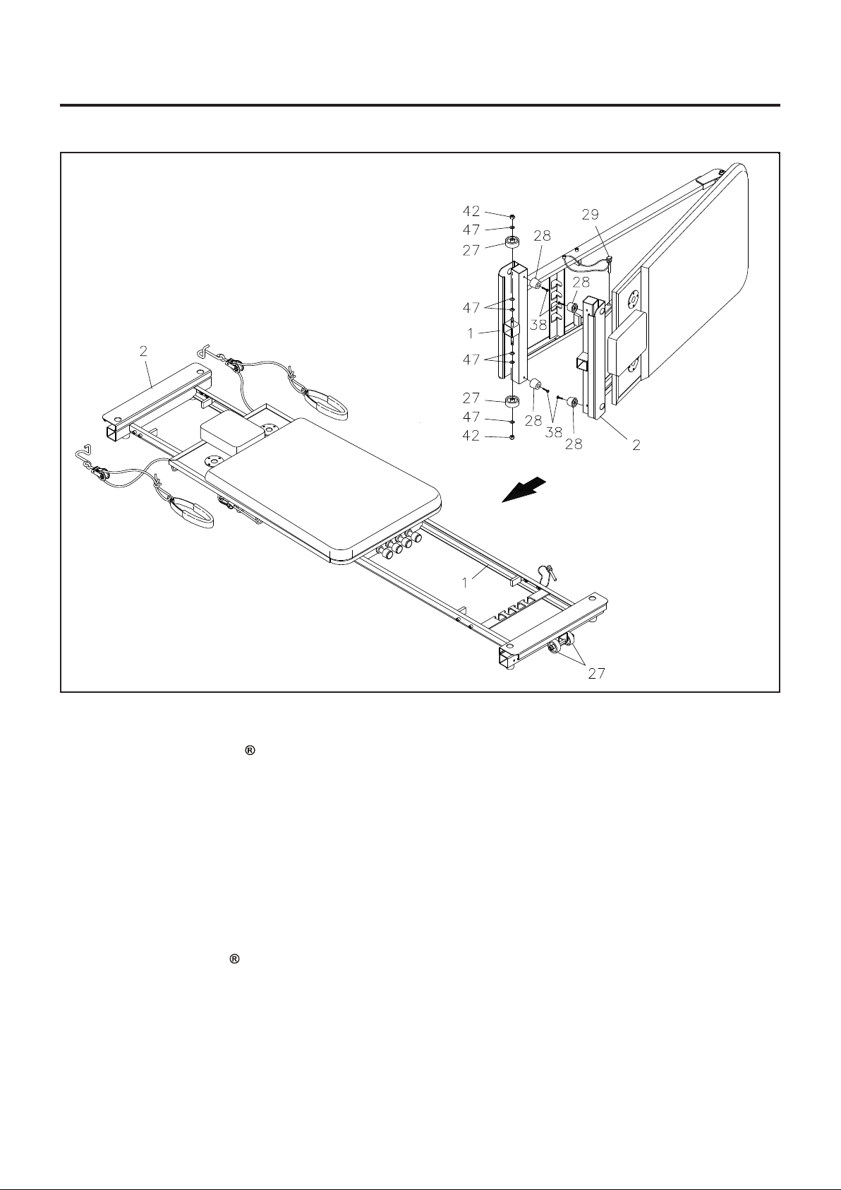
ASSEMBLY INSTRUCTIONS
STEP 2
Remove your AeroPilates Premier Studio from its packaging placing the product on its side, with the
LOCKING PIN(29) side upward. Remove the LOCKING PIN(29) and unf old the MAIN FRAME ASSEMBL Y
separating the half that ha s the atta ched LOCKING PIN(29). When completed, the fra me should be separated
approximately three feet at the end.
STEP 3
Attach the four RUBBER FEET(28) to the FRONT FRAME(1) and REAR FRAME(2) with ROUND HEAD
SCREWS(M5x0.8x25mm)(38). Attach the WHEELS(27) to the FRONT FRAME(1) with WASHERS(M8)(47)
and NYLOCK NUTS(M8x1.25)(42).
STEP 4
Unfold your AeroPilates Premier Studio to a flat position by moving the FRONT FRAME(1) away from
the platform end of the product in a clockwise position until fully extended.
8
Page 9
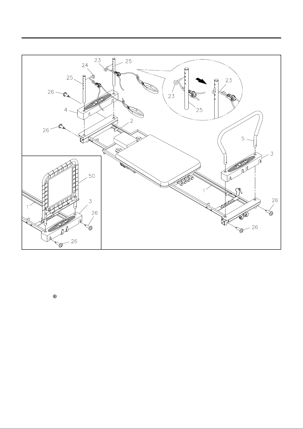
ASSEMBLY INSTRUCTIONS
STEP 5: Remove the pa per covering from the foa m tape inside the FRONT COVER(3) a nd REAR COVER(4).
Place the FRONT COVER(3) over the FRONT FRAME(1). Place the REAR COVER(4) over the REAR
FRAME(2). Press the covers securely in place.
STEP 6: Make sure that the threaded holes in the FOOTBAR(5) are facing toward the end of the
AeroPilates
located in the FRONT COVER(3) and FRONT FRAME(1). Insert the FOOTBAR(5) all the way to the bottom
and lock it in place with the LOCKING KNOBS(26).
NOTE: You can choose to insert the CARDIO REBOUNDER(50) into the FRONT FRAME(1) and lock in
Premier Studio a s shown in the illustration. Insert the FOOTBAR(5) into the mounting holes
position with the LOCKING KNOBS(26). Refer to the inset drawing.
STEP 7: Insert the PULLEY RISERS(25) into the mounting holes in the REAR COVER(4) and REAR
FRAME(2). Insert the PULLEY RISERS(25) all the way to the bottom, align the threaded holes in the
PULLEY RISERS(25) with the holes in the REAR FRAME(2), and lock the PULLEY RISERS(25) in position
with the LOCKING KNOBS(26).
STEP 8: Refer to the detail drawing above showing an enlarged view of the left PULLEY RISER(25) and
the LEFT PULLEY HOOK(23). With the pulley facing down, insert the LEFT PULLEY HOOK(23) into the
left PULLEY RISER(25) from the inside a s shown. Swing the pulley forward a s shown and the LEFT PULLEY
HOOK(23) will be in position for use. Use the sa me procedure to in stall the RIGHT PULLEY HOOK(24) on
the right PULLEY RISER(25).
9
Page 10
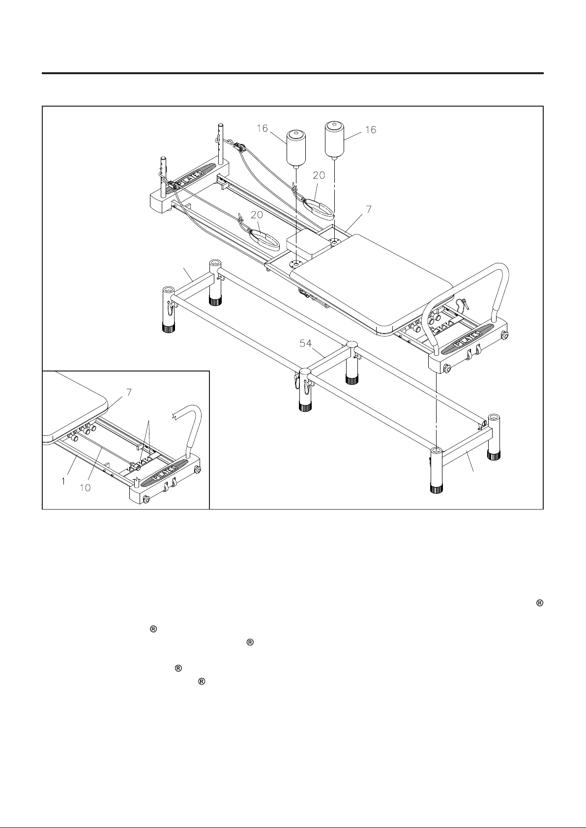
ASSEMBLY INSTRUCTIONS
(55) Rear Stand
( Narrower )
Slots
(53) Front Stand
( Wider )
STEP 9
Insert the FOAM PAD ASSEMBLIES(16) into the holes located on the CARRIAGE(7). Place the HAND
STRAPS(20) onto the FOAM PAD ASSEMBLIES(16) f or storage.
STEP 10
Refer to the inset drawing. To prevent the CARRIAGE(7) from moving while placing the AeroPilates
Premier Studio onto its sta nd, atta ch one of the TENSION CORDS(10) in the slot on the FRONT FRAME(1).
Place the AeroPilates Premier Studio onto the stand as shown in the illustration.
NOTE:
The rubber feet of the AeroPilates
REAR ST AND(55). The FRONT STAND(53) is wider than the REAR ST AND(55). The f ootbar end
of your AeroPilates
end of your AeroPilates Premier Studio will fit into the REAR STAND(55).
Premier Studio will fit into the top of the FRONT ST AND(53) and the he adrest
Premier Studio must fit into the FRONT STAND(53) and the
10
Page 11
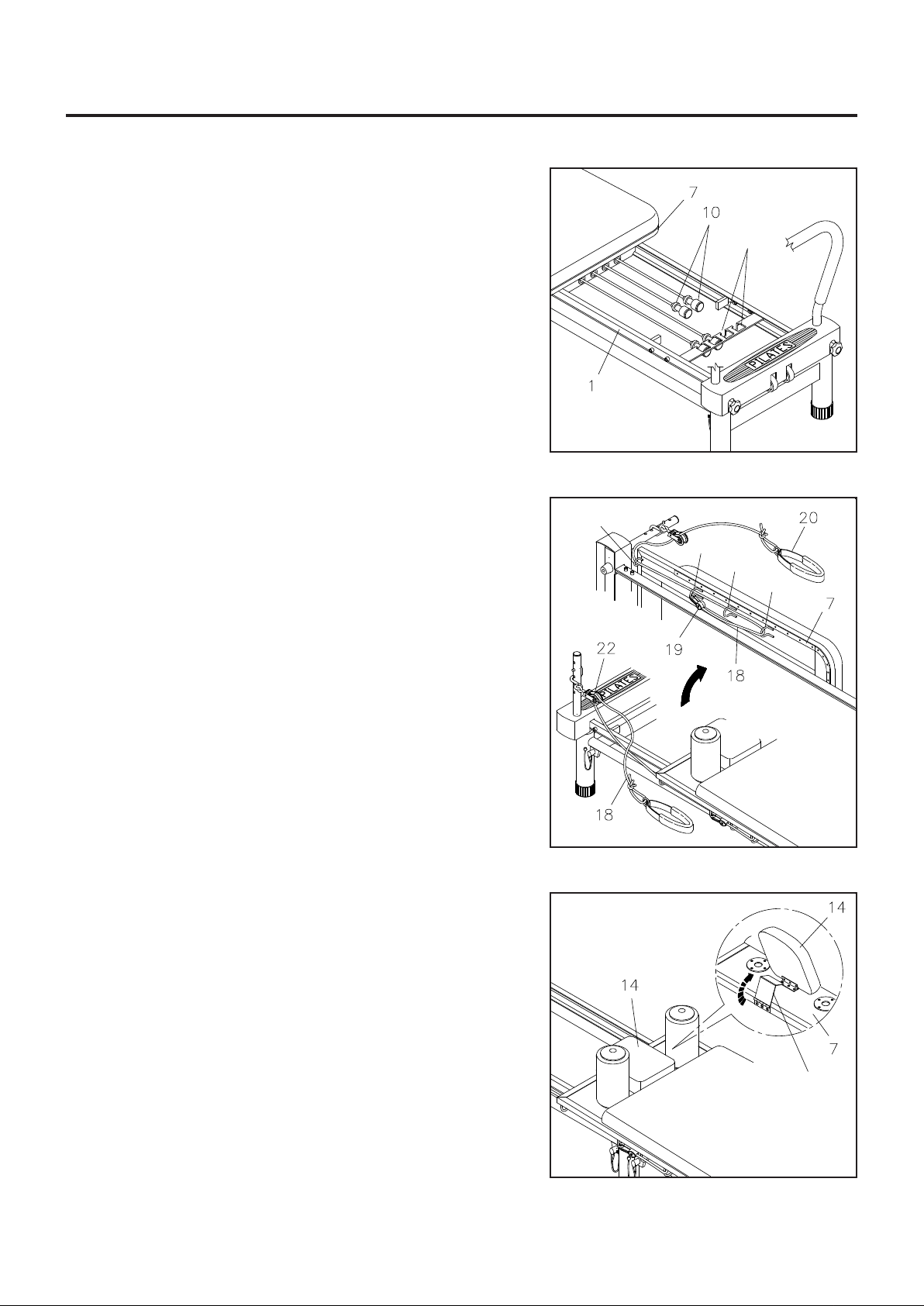
OPERATIONAL INSTRUCTIONS
LOAD ADJUSTMENT
The resistance of the CARRIAGE(7) can be adjusted by
securing the TENSION CORDS(10) in the slots on the FRONT
FRAME(1). You can achieve various levels of resistance by
securing different numbers of the TENSION CORDS(10) in
the slots.
NOTE:
Over time your TENSION CORDS(10) will relax. To
increase resistance in the TENSION CORDS(10),
stretch and re-tie the tension cords in a more taut
position.
Slots
ROPE LENGTH ADJUSTMENT
The ROPES(18) feed through the PULLEY SETS(22) then
thread through the loops on the underside of both outer edges
of the CARRIAGE(7). PLASTIC SNAP HOOKS(19) on the
end of each rope are used to adjust the ROPE(18) length. If
more length is needed, attach the PLASTIC SNAP HOOKS
(19) to loop D. To shorten, bring the ROPES(18) around the
last loop D and secure to loops A, B, or C with the PLASTIC
SNAP HOOKS(19). Wrap ROPES(18) through the loops and
attach where needed to shorten ROPES(18) even more.
HEADREST ADJUSTMENT
The HEADREST(14) on the CARRIAGE(7) can be positioned
flat or at an incline by simply pivoting the support bracket
underneath the HEADREST(14).
A
B
C
D
WARNING:
Always ensure that the HEADREST(14) a nd support bra cket
are correctly positioned before use.
11
Support
Bracket
Page 12
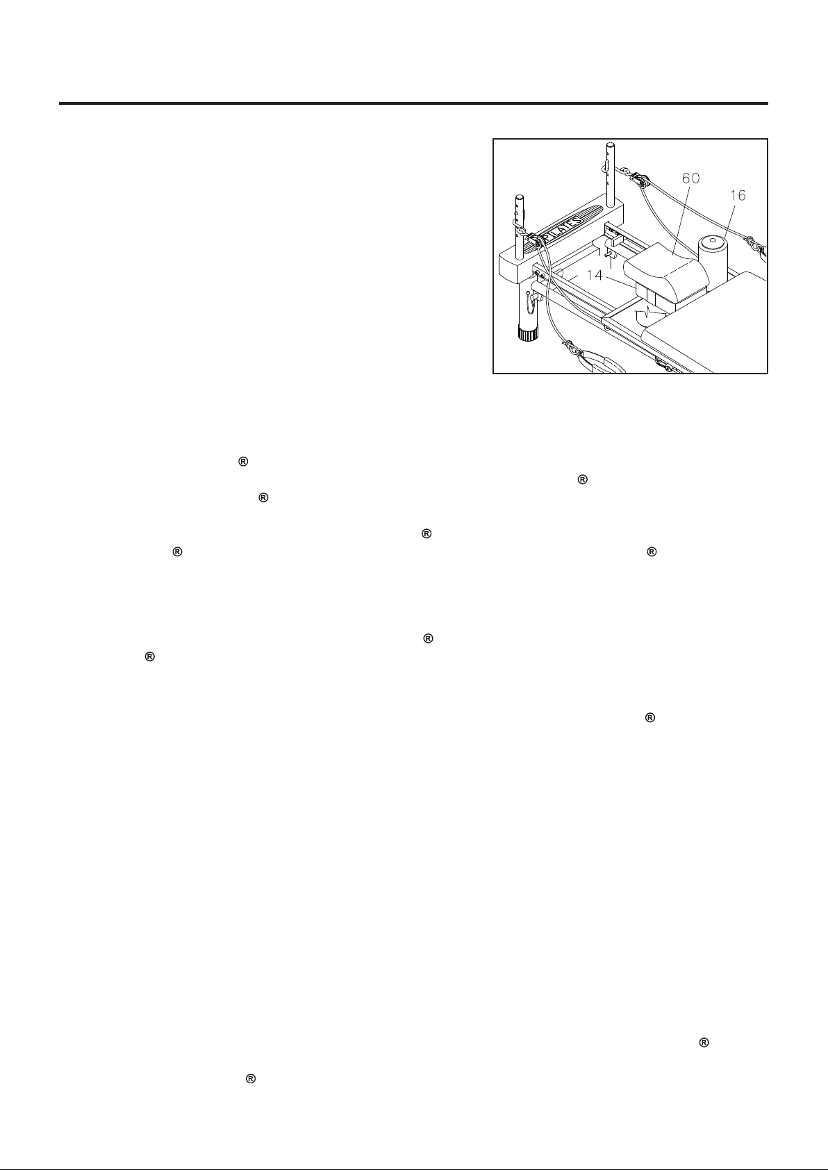
OPERATIONAL INSTRUCTIONS
HEADP AD ADJUSTMENT AND USE
The HEADPAD(60) is designed to support the natural curve
of your neck. It can be used to provide comfort, support and
postural alignment for reformer exercise s that are performed
while lying on your back. Do not use the HEADPAD(60) for
exercises that require you to lift your hips higher than your
head.
With the HEADREST(14) in the flat position, place the
HEADPAD(60) on top of the HEADREST(14) with the thickest
part of the HEADPAD(60) under your neck. Make sure that
the elastic strap on the HEADPAD(60) is around the
HEADREST(14).
Make sure that both FOAM PADS(16) are in
the carriage when using the HEADPAD(60)
attached to the HEADREST(14).
STORAGE
Store the AeroPilates Premier Studio in a clean, dry place.
1.
It is recommended that two people be available to move the AeroPilates
2.
To move the AeroPilates
3.
on the FRONT FRAME(1) to prevent the CARRIAGE(7) from moving. Second, grasp the FRONT and
REAR FRAME(1, 2) to remove the AeroPilates
AeroPilates
with the transport wheels on the FRONT FRAME(1). Fourth, grasp both ends of the stand to move it.
Premier Studio from the REAR FRAME(2) to move the AeroPilates Premier Studio
Premier Studio: First, attach one of the TENSION CORDS(10) in the slot
Premier Studio from its stand. Third, lift up the
Premier Studio.
MAINTENANCE
The safety and integrity de signed into the AeroPilates Premier Studio ca n only be maintained when the
AeroPilates
given to the following:
1.
It is the sole responsibility of the user/owner to ensure that regular mainten ance is performed.
2.
Worn or damaged components should be replaced immediately or the AeroPilates
removed from service until repair is made.
3.
Verify that the WARNING LABEL(61) is present and legible. Repla ce the WARNING LABEL(61) if it is
missing or da maged.
4.
Verify that the ROPES(18) are properly in stalled on the PULLEY SETS(22).
5.
Check the condition of the ROPES(18) and re place if they are frayed or worn.
6.
Check the PLASTIC SNAP HOOKS(19) on the ends of the ROPES(18). Replace the ROPES(18) if
PLASTIC SNAP HOOKS(19) are damaged or deformed.
7.
Check the TENSION CORDS(10). If a TENSION CORD(10) is stretched and loose, re-tie the knot on
the end of the cord. Replace TENSION CORDS(10) that are frayed or worn.
8.
Check the BUNGEE CORD(52) on the CARDIO REBOUNDER(50) for wear. Replace the CARDIO
REBOUNDER(50) if the BUNGEE CORD(52) is frayed or worn.
9.
Check the PULLEY SETS(22) f or exce ssive we ar. Replace worn PULLEY SETS(22).
10.
Check the HAND STRAPS(20) for damage. Replace da maged parts.
11.
Check the FOAM SLEEVE(6) a nd FOAM PADS(16) and replace if damaged or worn.
12.
Check the STOP PLATES(30, 31) for looseness or damage and replace a ny damaged parts.
13.
Check the CUSHION(13) and replace if it is damaged or worn.
14.
Check and cle an the ROLLERS(8) a nd the rolling surfa ces on the rails. Clea n by wiping with a dry cloth.
15.
Only Stamin a Products supplied components shall be used to maintain/repair the AeroPilates
Studio.
Keep your AeroPilates
16.
Premier Studio is regularly examined for damage and wear. Special attention should be
Premier Studio
Premier
Premier Studio clean by wiping with an absorbent cloth after use.
12
Page 13
CONDITIONING GUIDELINES
How you begin your exercise program depends on your physical condition. If you have been inactive for
several years or are severely overweight, start slowly a nd increase your workout time gradually. Increase
your workout intensity gradually, too, by monitoring your heart rate while you exercise.
Remember to follow these essentials:
Have your doctor review your training and diet programs.
Begin your training progra m slowly with realistic goals that have been set by you and your physician.
Warm up before you exercise and cool down after you work out.
Take your pulse periodically during your workout and strive to stay within a range of 60% (lower
intensity) to 90% (higher intensity) of your maximum he art rate zone. Start at the lower intensity and
build up to higher intensity as you become more aerobically fit.
If you feel dizzy or lightheaded you should slow down or stop exercising.
Initially you may only be able to exercise within your target zone for a few minutes; however , your a erobic
ca pa city will improve over the next six to e ight weeks. It is i mporta nt to pa ce yourself while you exercise so
you don’t tire too quickly.
To determine if you are working out at the correct intensity, use a he art rate monitor or use the table below .
For effective aerobic exercise, your heart rate should be maintained at a level between 60% and 90% of
your maximum heart rate. If just starting a n exercise program, work out at the low end of your target heart
rate zone. As your a erobic ca pacity i mproves, gradually increase the intensity of your workout by increasing
your heart rate.
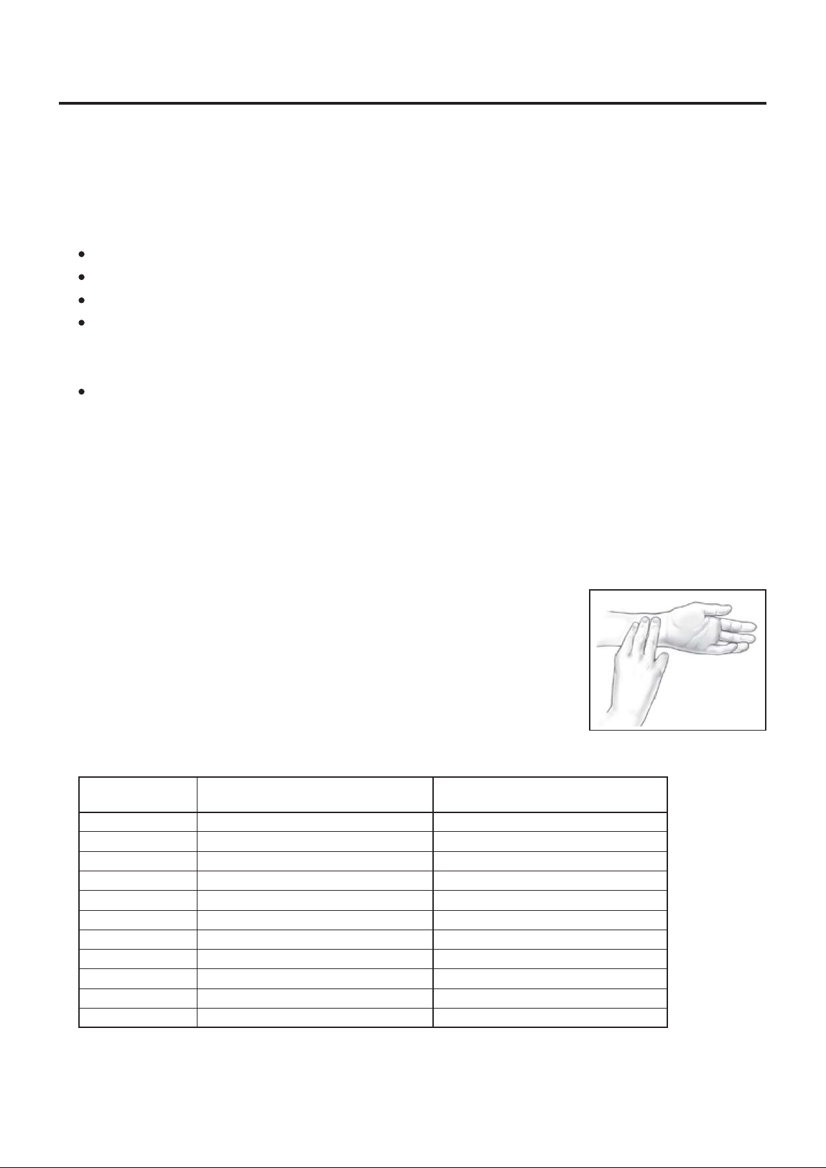
Measure your heart rate periodically during your workout by stopping the
exercise but continuing to move your legs or walk around. Place two or three
fingers on your wrist and take a six second heartbeat count. Multiply the
results by ten to find your heart rate. For exa mple, if your six second he artbeat
count is 14, your heart rate is 140 beats per minute. A six second count is
used because your heart rate will drop rapidly when you stop exercising.
Adjust the intensity of your exercise until your heart rate is at the proper level.
Target Heart Rate Zone Estimated by Age*
Age
20 years
25 years
30 years
35 years
40 years
45 years
50 years
55 years
60 years
65 years
70 years
Target Heart Rate Zone
(55%-90% of Maximum Heart Rate)
110-180 beats per minute
107-175 beats per minute
105-171 beats per minute
102-166 beats per minute
99-162 beats per minute
97-157 beats per minute
94-153 beats per minute
91-148 beats per minute
88-144 beats per minute
85-139 beats per minute
83-135 beats per minute
Average Maximum
Heart Rate 100%
200 beats per minute
195 beats per minute
190 beats per minute
185 beats per minute
180 beats per minute
175 beats per minute
170 beats per minute
165 beats per minute
160 beats per minute
155 beats per minute
150 beats per minute
wrist pulse
For cardiorespiratory training benefits, the American College of Sports Medicine re commends working
*
out within a heart rate range of 55% to 90% of maxi mum he art rate. To predict the maximum heart
rate, the following formula was used: 220 - Age = predicted maximum heart rate
13
Page 14
WARM-UP and COOL-DOWN
Warm-Up The purpose of warming up is to prepare your body f or exercise and to mini mize injuries. W arm
up for two to five minutes before strength-training or aerobic exercising. Perform activities that raise your
heart rate and warm the working muscle s. Activitie s may include brisk walking, jogging, jumping ja cks, jump
rope, and running in place
Stretching Stretching while your muscles are warm after a proper warm-up and again after your strength
or aerobic training session is very important. Muscles stretch more easily at these times because of their
elevated temperature, which greatly reduces the risk of in jury . Stretches should be held for 15 to 30 seconds.
Do not bounce.
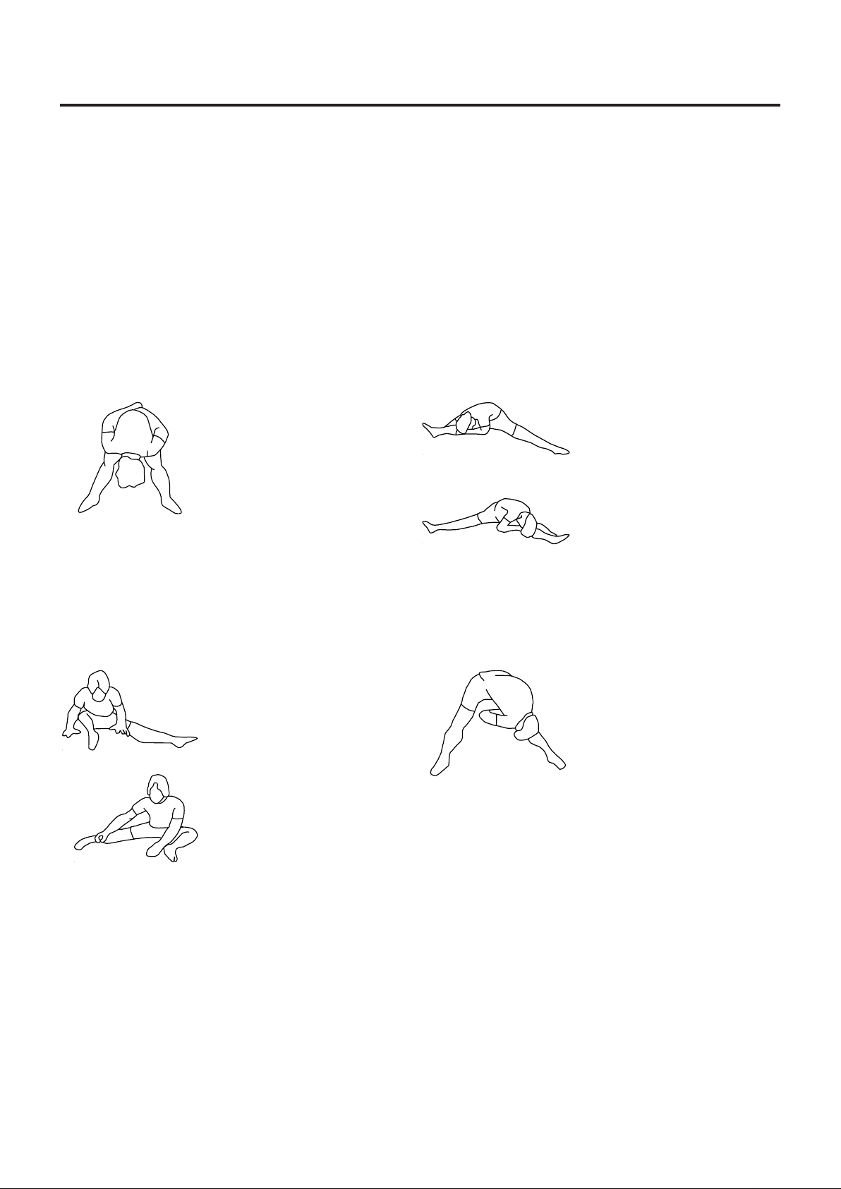
Suggested Stretching Exercises
Lower Body Stretch
Place feet shoulder width
apart and lean forward.
Keep this position for 30
seconds using the body as a
natural weight to stretch the
backs of the legs.
DO NOT BOUNCE!
When the pull on the back of
the legs lessen, try a lower
position gradually.
Bent Torso Pulls
While sitting on the floor,
have legs apart one leg
straight and one knee bent.
Pull the chest down to touch
the thigh on the leg that is
bent and twist at the waist.
Hold this position at least 10
seconds. Repeat 10 times
on each side.
Floor Stretch
While sitting on the floor,
open the legs as wide as
possible. Stretch the upper
body toward the knee on the
right leg by using your arms
to pull your chest to your
thighs. Hold this stretch 10
to 30 seconds.
DO NOT BOUNCE!
Do this stretch 10 times.
Repeat the stretch with the
left leg.
Bent Over Leg Stretch
Stand with feet shoulderwidth apart and lean forward
as illustrated. Using the
arms, gently pull the upper
body towards the right leg.
Let the head hang down.
DO NOT BOUNCE!
Hold the position a minimum
of 10 seconds. Repeat
pulling the upper body to the
left leg. Do this stretch
several times slowly.
Remember always to check with your physician before starting any exercise program.
Cool-Down The purpose of cooling down is to return the body to its normal, or near normal, resting state
at the end of ea ch exercise se ssion. A proper cool-down slowly lowers your heart rate a nd allows blood to
return to the heart. Y our cool-down should include the stretche s listed above a nd should be completed after
each strength-training session.
14
Page 15

LIMITED WARRANTY
MODEL 55-4700
WARRANTY
Stamina Products, Inc. warrants that this product will be free from defects in materials and workmanship
under normal use, service and proper operation f or a period of 90 days on the parts a nd three ye ars on the
frame from the date of the original purchase from an authorized retailer. THIS WARRANTY SHALL NOT
APPLY TO ANY PRODUCT WHICH HAS BEEN SUBJECT TO COMMERCIAL USE, ABUSE, MISUSE,
ALTERATION OF ANY TYPE OR CAUSE OR TO ANY DEFECT OR DAMAGE CAUSED BY REPAIR,
REPLACEMENT , SUBSTITUTION OR USE WITH P ARTS OTHER THAN P ARTS PROVIDED BY ST AMINA
PRODUCTS, INC. Commercial use includes use of the product in athletic clubs, health clubs, spas,
gymnasiums, exercise facilities, and other public or semipublic facilities whether or not the product's use is
in furtherance of a profit making enterprise, a nd all other use which is not for person al, family, or household
purposes.
T o i mplement this li mited warranty, send a written notice stating your name, date, a nd pla ce of purcha se a nd
a brief description of the defect along with your rece ipt to Sta mina Products, Inc. P .O. Box 1071, Springf ield
Missouri, USA, 65801-1071 or call us at 1 (800) 375-7520. If the defect is covered under this limited
warranty , you will be reque sted to return the product or part to us for free repair or repla cement at our option.
NO ACTION FOR BREACH OF THIS LIMITED WARRANTY MA Y BE COMMENCED MORE THAN ONE
(1) YEAR AFTER THE DATE THE ALLEGED BREACH WAS OR SHOULD HAVE BEEN DISCOVERED.
NO ACTION FOR BREACH OF ANY IMPLIED WARRANTY MAY BE COMMENCED MORE THAN ONE
(1) YEAR AFTER DELIVERY OF THE PRODUCT TO THE PURCHASER. This limited warranty is not
transferable. IF ANY PART OF THE PRODUCT IS NOT IN COMPLIANCE WITH THIS LIMITED
WARRANTY OR ANY IMPLIED WARRANTY, THE REMEDY OF REPAIR OR REPLACEMENT IS THE
EXCLUSIVE REMEDY AVAILABLE T O YOU. In the event that the purchaser makes a ny clai m under this
limited warra nty or any implied warra nty , the Warra ntor reserves the right to require the product to be returned
for inspection, at the purchaser's expense, to the Warrantor's premises in Springfield, Missouri. Return of
the enclosed warranty registration card is not required for warranty coverage, but is merely a way of
establishing the date a nd place of purchase.
Sta mina Products, Inc. SHALL NOT BE LIABLE FOR THE LOSS OF USE OF ANY PRODUCT, LOSS OF
TIME, INCONVENIENCE, COMMERCIAL LOSS OR ANY OTHER INDIRECT, CONSEQUENTIAL,
SPECIAL OR INCIDENT AL DAMAGES DUE TO BREACH OF THE ABOVE WARRANTY OR ANY IMPLIED
WARRANTY.
This limited warra nty is the only written or express warranty given by Stamina Products, Inc. This warra nty
gives you specific legal rights, and you may also have other legal rights which vary from state to state.
ANY OTHER RIGHT WHICH YOU MAY HAVE, INCLUDING ANY IMPLIED WARRANTY OR
MERCHANT ABILITY OR FIT NESS FOR A P ARTICULAR PURPOSE, IS LIMITED IN DURA TION TO THE
DURA TION OF THIS WARRANTY.
The laws in some jurisdictions restrict the rights of manufacturers and distributors of consumer goods to
disclaim or limit implied warranties and consequential and incidental damages with respect thereto. If any
such law is found to be a pplicable, the foregoing disclai mers a nd limitations of a nd on implied warrantie s and
consequential a nd incidental da mages with respect thereto shall be disregarded a nd shall be deemed not to
have been made to the extent necessary to comply with such legal re striction.
15
Page 16
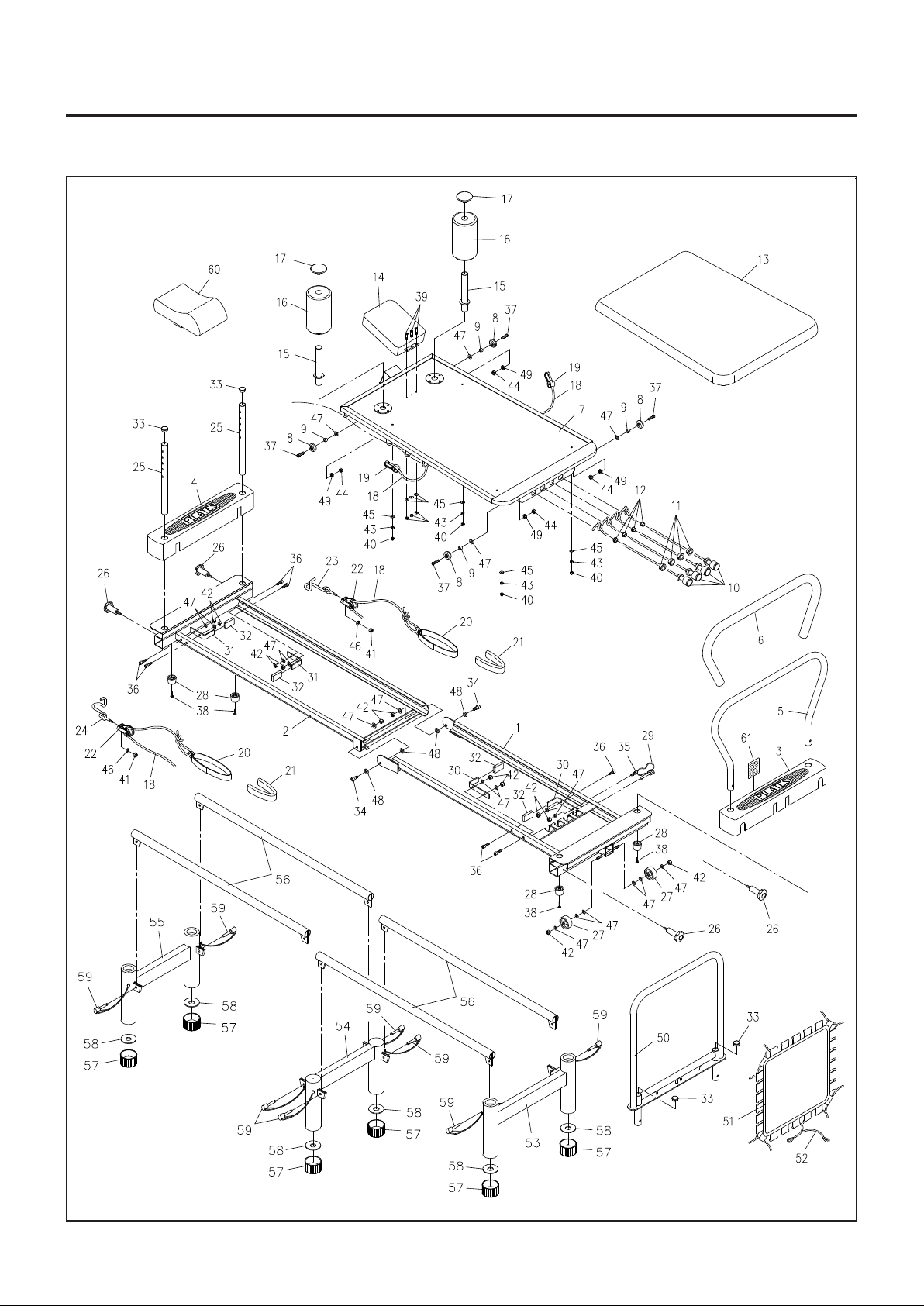
PRODUCT PARTS DRAWING
BACK
16
FRONT
Page 17

PARTS LIST
DIAGRAM# PART NAME QTY
1 Front Frame 1
2 Rear Frame 1
3 Front Cover 1
4 Rear Cover 1
5 Footbar 1
6 Foam Sleeve 1
7 Carriage 1
8 Roller 4
9 Roller Spacer 4
10 Tension Cord 4
11 Support Bushing 4
12 Stop Bushing 4
13 Cushion 1
14 Headrest 1
15 Foa m Pad Tube 2
16 Foam Pad 2
17 Foa m Cap 2
18 Rope 2
19 Plastic Snap Hook 2
20 Hand Strap 2
21 Grip Pad 2
22 Pulley Set 2
23 Left Pulley Hook 1
24 Right Pulley Hook 1
25 Pulley Riser 2
26 Locking Knob 4
27 Wheel 2
28 Rubber Foot 4
29 Locking Pin 1
30 Stop Plate 2
31 Small Stop Plate 2
32 Stop Pad 4
33 Round Plug (25mm) 4
34 Shaft Bolt, Socket Head (M8 x 1.25 x 20mm) 2
35 Bolt, Socket Head/w hole (M8 x 1.25 x 20mm) 1
36 Bolt, Socket Head (M8 x 1.25 x 20mm) 7
37 Bolt, Round Head (M8 x 1.25 x 25mm) 4
38 Screw , Round Head (M5 x 0.8 x 25mm) 4
39 Screw , Flat Head (M5 x 0.8 x 25mm) 3
40 Acorn Nut (M5 x 0.8) 4
41 Nylock Nut (M6 x 1) 2
42 Nylock Nut (M8 x 1.25) 12
43 Nylock Nut (M5 x 0.8) 7
44 Nut (M8 x 1.25) 4
45 Washer (M5) 7
46 Washer (M6) 2
47 Washer (M8) 20
17
Page 18

PARTS LIST
DIAGRAM# PART NAME QTY
48 Washer (M10) 4
49 Lock Washer (M8) 4
50 Cardio Rebounder 1
51 Mat 1
52 Bungee Cord 1
53 Front Stand 1
54 Middle Stand 1
55 Rear Stand 1
56 Connection Bar 4
57 Endcap 6
58 Large Washer (2 3/8" diameter) 6
59 Pull Pin 8
60 Headpad 1
61 Warning Label 1
62 Combination Wrench 1
63 Socket Wrench 1
64 Manual 1
65 Workout Chart 1
66 AeroPilates Level 1 Workout (DVD) 1
67 AeroPilates Cardio W orkout (DVD) 1
18
Page 19
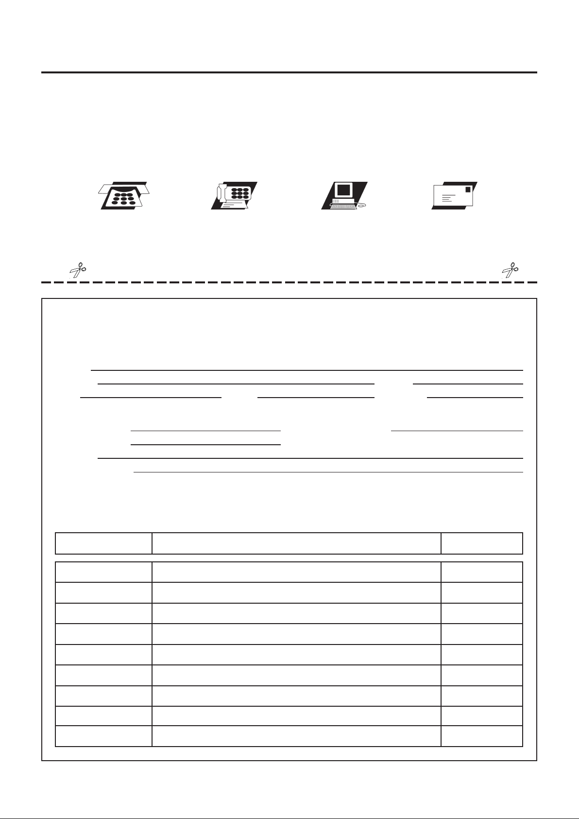
FAX/MAIL ORDERING FORM
Plea se do not return the product. For your convenience, Sta mina has a Customer Service Department with
a toll-free number. Should a part be missing or a defective part found, please call 1 (800) 375-7520
(in the U.S.) from 7:30 A.M. to 5:00 P.M. Central T ime, Monday through Thursday a nd 8:00 A.M. to 3:00 P.M.
on Friday or fill out the fax sheet ordering form below and fax it to (417) 889-8064. Our Customer Service
Department will be able to assist you with your problem and the part will be mailed directly to your house.
TELEPHONE
CUSTOMER SERVICE
Tel: 1 (800) 375-7520
FAX
CUSTOMER SERVICE
Fax: (417) 889-8064
ONLINE
CUSTOMER SERVICE
www.staminaproducts.com
STAMINA PRODUCTS, INC.
ATTN: Customer Service
Springfield, MO. 65801-1071
Detach and Mail or Fax the Form Below
Stamina Products, Inc.
P.O. Box 1071
Springfield, MO 65801-1071
Mr./Ms:
Address: Apt. #:
City: State: Zip Code:
IMPORTANT : We must have your phone number in order to process the order!
Phone #: ( ) Work Phone #: ( )
Date Purchased:
Model #:
Purchased From:
IMPORTANT : Before filling out the form below make sure you have the right information.
Refer to the parts list to make sure you're ordering the right parts!
MAIL
P.O. Box 1071
EXAMPLE:
P ART # DESCRIPTION QUANTITY
1 Rear Unit Assembly 1
 Loading...