

Stamford P0, P1 Service And Maintenance Instructions

P0/P1 AC Generators
INSTALLATION, SERVICE AND
MAINTENANCE
English
Original Instructions
A040J847 (Issue 4)


Table of Contents
1. FOREWORD......................................................................................................................... 1
2. SAFETY PRECAUTIONS...................................................................................................... 3
3. SAFETY DIRECTIVES AND STANDARDS.......................................................................... 7
4. INTRODUCTION................................................................................................................... 9
5. AUTOMATIC VOLTAGE REGULATORS (AVR)................................................................. 13
6. APPLICATION OF THE GENERATOR............................................................................... 15
7. INSTALLATION INTO THE GENERATING SET................................................................ 19
8. SERVICE & MAINTENANCE.............................................................................................. 29
9. FAULT FINDING ................................................................................................................. 49
10. PARTS IDENTIFICATION................................................................................................... 67
11. TECHNICAL DATA.............................................................................................................. 71
12. SPARES AND AFTER SALES SERVICE........................................................................... 73
13. END OF LIFE DISPOSAL ................................................................................................... 75
A040J847 (Issue 4) i

-
This page is intentionally blank.
ii A040J847 (Issue 4)

1 Foreword
1.1 The Manual
This manual contains guidance and instructions for the installation, servicing and
maintenance of the generator.
Before operating the generator, read this manual and make sure that all personnel who work
on the equipment have access to the manual and all additional documentation supplied with
it. Misuse and failure to follow the instructions, and the use of non-approved parts, may
invalidate the product warranty and lead to potential accidents.
This manual is an essential part of the generator. Make sure that the manual is available to
all users throughout the life of the generator.
The manual is written for skilled electrical and mechanical technicians and engineers, who
have prior knowledge and experience of generating equipment of this type. If in doubt,
please seek expert advice or contact your local Cummins Generator Technologies
subsidiary.
Information in this manual was correct when published. It may be superseded due to our
policy of continuous improvement. Please visit www.cumminsgeneratortechnologies.com for
latest documentation.
NOTICE
A040J847 (Issue 4) 1

-
This page is intentionally blank.
2 A040J847 (Issue 4)
2 Safety Precautions
2.1 Safety Information and Notices used in this manual
Danger, Warning and Caution panels are used in this manual to describe the sources of
hazards, their consequences and how to avoid injury. Notice panels emphasise important or
critical instructions.
DANGER
Danger indicates a hazardous situation which, if not avoided, WILL result in death or serious
injury.
WARNING
Warning indicates a hazardous situation which, if not avoided, COULD result in death or
serious injury.
CAUTION
Caution indicates a hazardous situation which, if not avoided, COULD result in minor or
moderate injury.
NOTICE
Notice refers to a method or practice which can result in product damage, or to draw
attention to additional information or explanations.
2.2 Skill Requirements of Personnel
WARNING
Service and maintenance procedures should only be carried out by experienced and qualified
engineers, who are familiar with the procedures and the equipment.
2.3 Risk Assessment
WARNING
A risk assessment should be performed by the user/operating company to establish all
personnel-related risks. All affected users must be trained on the identified risks. Access to
the Power Plant/Generating Set during operation must be restricted to persons who have
been trained on these risks.
2.4 Personal Protective Equipment (PPE)
WARNING
All persons operating, servicing, maintaining or working in or with a power plant or a
generating set must wear appropriate Personal Protective Equipment (PPE).
A040J847 (Issue 4) 3

-
Recommended PPE includes:
• Ear and Eye Protection
• Head and face protection
• Safety footwear
• Overalls that protect the lower arms and legs
Ensure that all persons are fully aware of the emergency procedures in case of accidents.
2.5 Noise
Generators emit noise. Wear appropriate ear protection at all times. Maximum A-weighted
noise emissions may reach 97 dB(A). Contact the supplier for application-specific details.
2.6 Electrical Equipment
CAUTION
All electrical equipment can be dangerous if not operated correctly. Always install, service
and maintain the generator in accordance with this manual.
Work that requires access to electrical conductors must comply with all applicable local and
national electrical safety procedures for the voltages involved and any site specific rules.
Always use genuine branded replacement parts.
2.7 Lock Out/Tag Out
Isolate the generator from all sources of mechanical and electrical energy before starting
service or maintenance work. Adopt a suitable lock-out/tag out process.
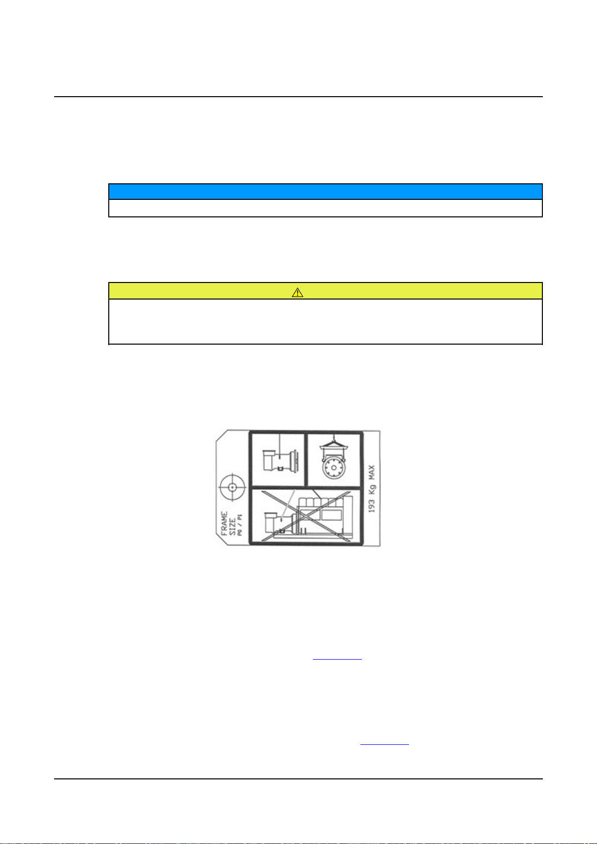
2.8 Lifting
The lifting points provided are designed for lifting the generator only. Do not use the
generator lifting points to lift the complete generating set (generator coupled to motive power
source).
Do not remove the lifting label attached to one of the lifting points.
CAUTION
WARNING
WARNING
2.9 Generator Operating Areas
WARNING
In the event of catastrophic failure, machine parts may be ejected from the generator air
inlet/outlet (shaded regions of diagram). Do not place controls near the air inlet/outlet and
restrict personnel from these regions during machine running.
4 A040J847 (Issue 4)

2.10 Hazard Warning Labels
Hazard warning labels are fixed to the generator. If the original labels are missing, damaged
or painted over, replace them with the spare set supplied in a wallet attached to the
generator. Label locations are shown on the back of the label set.
-
2.11 General Guidance
NOTICE
These safety precautions are for general guidance and supplement your own safety
procedures and all applicable laws and standards.
A040J847 (Issue 4) 5

-
This page is intentionally blank.
6 A040J847 (Issue 4)

3 Safety Directives and Standards
STAMFORD AC generators meet applicable European safety directives, and national and
international standards relevant to generators. The generator must be operated within the
limits specified in the relevant standards and within the parameters on the generator rating
plate.
Marine generators meet the requirements of all the major marine classification societies.
3.1 European Directives: EC Declaration of Conformity for Incorporation
Each generator supplied in the European Economic Area (EEA) is supplied with an EC
Declaration of Conformity for Incorporation into an electricity generating set. It is the
responsibility of the generating set manufacturer to ensure that the complete generating set
complies with EC Directives and standards.
Our authorized representative in the European Community is Mr Jeffrey Matthews,
Engineering Director, Cummins Generator Technologies Ltd.
All generators meet the following Standards and Directives:
Directives:
• 2004/108/EC EMC Directive
• 2006/95/EC Low Voltage Directive
• 2006/42/EC Machinery Directive
Standards:
• EN 61000-6-1 Electromagnetic Compatibility, Generic Standards - Immunity for
residential, commercial and light-industrial environments
• EN 61000-6-2 Electromagnetic Compatibility, Generic Standards - Immunity for
industrial environments
A040J847 (Issue 4) 7

-
• EN 61000-6-4 Electromagnetic Compatibility, Generic Standards - Emission standard
for light-industrial environments
• EN ISO 12100-1 Safety of Machinery, Basic concepts, general principles for design Basic terminology, methodology
• EN ISO 12100-2 Safety of Machinery, Basic concepts, general principles for design Technical principles
• EN ISO 14121-1 Safety of Machinery, Risk assessment - Principles
• EN 60034-1 Rotating electrical machines - Rating and performance
• BS ISO 8528-3 Reciprocating internal combustion engine driven alternating current
generating sets - alternating current generators for generating sets
• BS 5000-3 Rotating electrical machines - Generators to be driven by reciprocating
internal combustion engines - Requirements for resistance to vibration
NOTICE
Once the generator is built into a generating set, it is the responsibility of the generating set
manufacturer to ensure that the generating set complies with the relevant specifications and
standards.
3.2 Additional Information for EMC Compliance
STAMFORD generators are designed to meet EMC emissions and immunity standards for
industrial environments. Document reference N4/X/011 outlines additional equipment that
may be required when the generator is installed in residential, commercial and light industrial
environments.
The installation ‘earth/ground’ arrangements require the connection of the generator frame to
the site protective earth conductor using a minimum lead length.
Installation, maintenance and servicing must be carried out by adequately trained personnel
fully aware of the requirements of the relevant EC directives.
NOTICE
Cummins Generator Technologies is not liable for EMC compliance if unauthorised parts, not
of STAMFORD brand, are used for maintenance and servicing.
3.3 Additional Information for CSA Compliance
To comply with Canadian Standards Association (CSA) regulations, all external wiring and
components must be rated at the generator rated voltage shown on the rating plate label.
8 A040J847 (Issue 4)

4 Introduction
4.1 General Description
P0/P1 generators are of brushless rotating field design, available up to 600V, 50Hz (1500
RPM, 4 pole and 3000 RPM, 2 pole) or 60Hz (1800 RPM, 4 pole and 3600 RPM, 2 pole),
and built to meet B.S. 5000 Part 3 and other international standards.
P0/P1 are self-excited, with excitation power derived from the main output windings using
the AS480 AVR.
4.2 Serial Number Location
A unique serial number is stamped into the top of the generator frame near the drive end
and shown on the rating plate and tracking labels on the side of the generator frame.
4.3 Rating Plate
The fixed rating plate label states the intended operating parameters of the generator.
The generator could overheat if operated outside the parameters specified on the rating plate.
Overheating can cause catastrophic failure and injury from ejected debris. Always operate
the generator within the rated parameters.
WARNING
4.4 Product Authentication
The STAMFORD high security, anti-counterfeit hologram is located on the Tracking
Label. Check that the dots are visible around the STAMFORD logo when viewing the
hologram from different angles and the word "GENUINE" appears behind the logo. Use a
flashlight to see these security features in low ambient light. Check that the generator is
genuine by entering the unique 7 character hologram code at www.stamford-
avk.com/verify.
FIGURE 1. GLOBAL STAMFORD AC GENERATOR NAMEPLATE, COMPRISING RATING PLATE
(ABOVE) AND TRACKING LABEL (BELOW)
A040J847 (Issue 4) 9

-
FIGURE 2. DOTS VISIBLE IN LEFT, RIGHT, UPPER AND LOWER VIEWS OF 3D HOLOGRAM
10 A040J847 (Issue 4)
4.5 Self-Excited AVR Controlled Generators
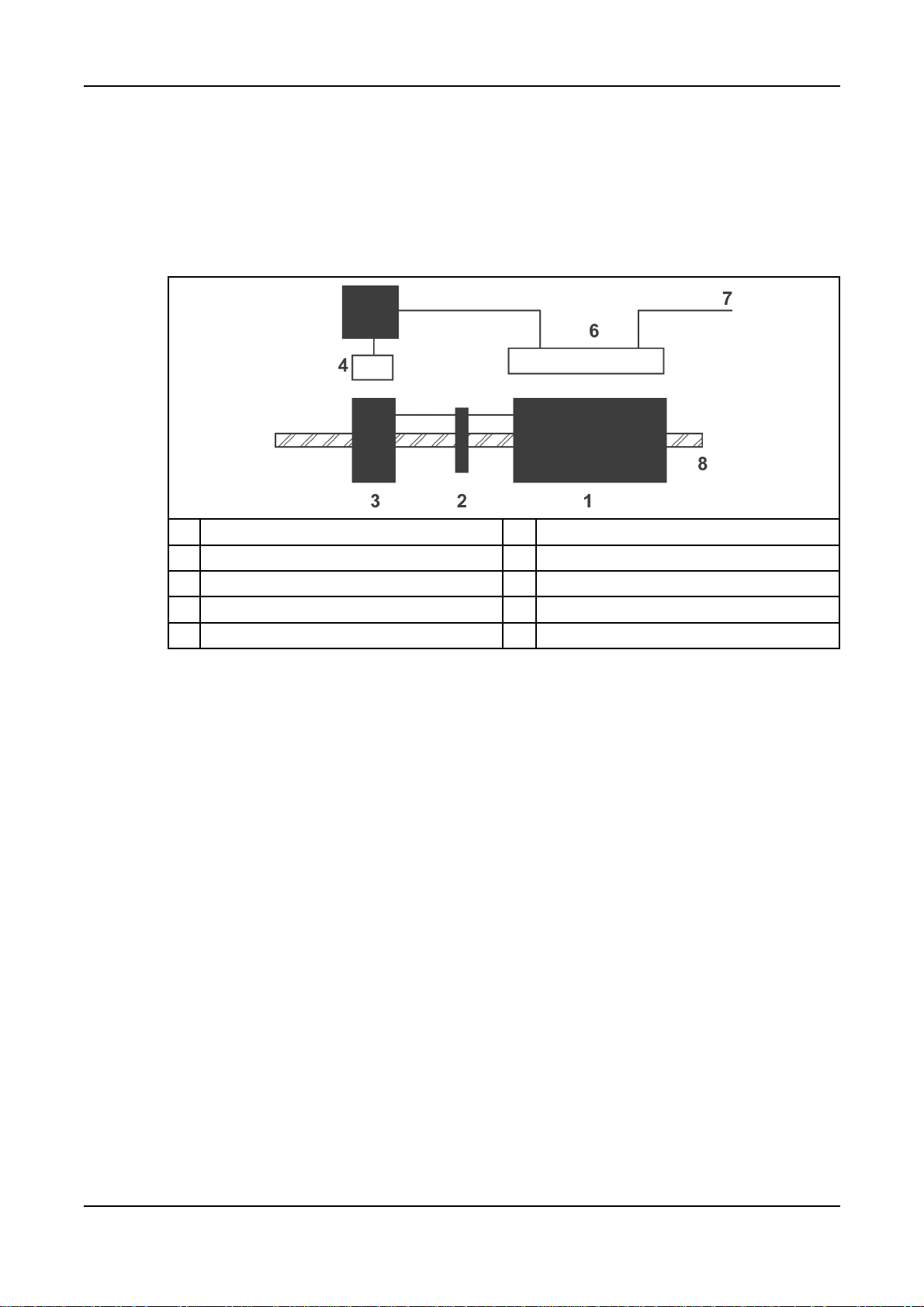
4.5.1 Main Stator Powered AVR
The AVR provides closed loop control by sensing the generator output voltage at the main
stator windings and applying voltage to the exciter stator. Voltage induced in the exciter
rotor, rectified by the rotating diodes, magnetises the main rotor which induces voltage in the
main stator windings. The AVR is also powered by the main stator.
-
No. Description No. Description
1 Main rotor 5 AVR
2 Rotating diodes 6 Main stator
3 Exciter rotor 7 Output
4 Exciter stator 8 Shaft
4.6 Separately-Excited AVR Controlled Generators
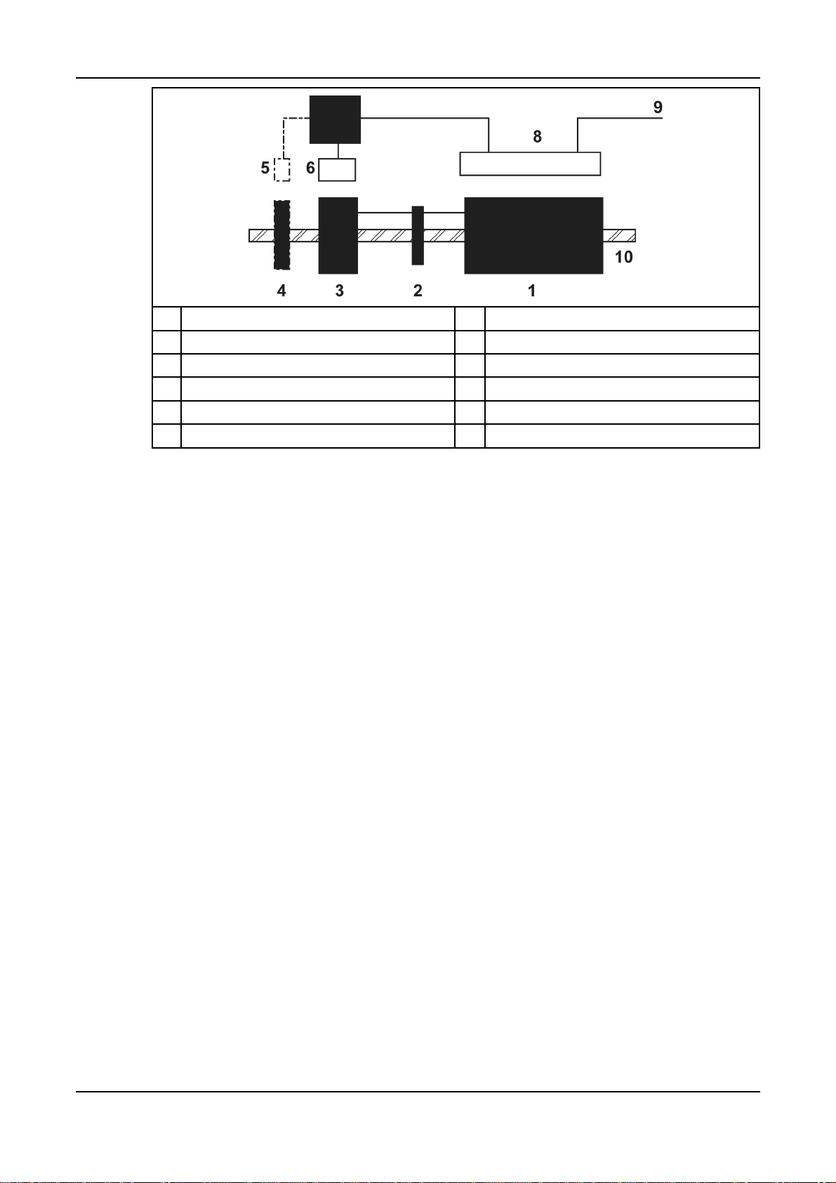
4.6.1 Excitation Boost System (EBS)
The EBS is a self-contained optional unit, attached to the non-drive end of the generator.
The EBS unit consists of the Excitation Boost Controller (EBC) and an Excitation Boost
Generator (EBG). Under fault conditions, or when the generator is subjected to a large
impact load such as a motor starting, the generator voltage drops. The EBC senses the drop
in voltage and engages the output power of the EBG. This additional power feeds the
generator’s excitation system, supporting the load until the generator voltage recovers or
breaker discrimination removes the fault.
A040J847 (Issue 4) 11
-
No. Description No. Description
1 Main rotor 6 Exciter stator
2 Rotating diodes 7 AVR & EBS
3 Exciter rotor 8 Main stator
4 EBG rotor (optional) 9 Output
5 EBG stator (optional) 10 Shaft
12 A040J847 (Issue 4)

5 Automatic Voltage Regulators (AVR)
Cummins Generator Technologies offer a selection of Automatic Voltage Regulators (AVRs)
designed and built to achieve maximum performance from the range of STAMFORD
brushless AC generators. Self-excited and separately-excited types are available, from lowcost analogue to sophisticated digital control. All STAMFORD AVRs are encapsulated to
provide environmental protection, and are mounted on anti-vibration mounts for added
mechanical protection.
All STAMFORD AVRs have the following features:
• connections to a remote hand trimmer accessory for fine control of the generator output
voltage
• ‘Under-Frequency Roll-Off’ (UFRO) protection to reduce the generator output voltage if
speed falls below a threshold, and
• connections to power factor and droop accessories for sharing reactive load in parallel
with other generators or mains utility.
AVR specification, installation and adjustment information is available in the AVR manual
supplied with the generator, or at www.cumminsgeneratortechnologies.com
NOTICE
AVR analogue inputs must be fully floating (galvanically isolated from ground), with
an insulation strength of 500 V a.c.
5.1 Self-Excited
A self-excited AVR receives power from the generator output terminals. The AVR controls
the generator output voltage by automatic adjustment of the exciter stator field strength.
5.1.1 AS480
The AS480 achieves voltage regulation of ±1.0%. The design employs surface mount
technology, custom mouldings and heatsink in a compact assembly.
The AVR includes the following extra features:
• connections to an Excitation Boost System accessory, and
• connection of a lead assembly for low voltage (100 V to 120 V a.c.) sensing.
5.2 AVR Accessories
Accessories to support AVR functions are factory-fitted or supplied separately with
instructions for fitting and wiring by a competent technician.
5.2.1 Hand Trimmer (for remote voltage adjustment)
A hand trimmer can be fitted in a convenient position (typically in the generator set control
panel) and connected to the AVR to provide fine adjustment of the generator voltage. The
hand trimmer value and the adjustment range obtained is as defined in the Technical
Specification. Refer to wiring diagram before removing the shorting link and connecting the
hand trimmer.
A040J847 (Issue 4) 13

-
5.2.2 Droop Transformer (for parallel operation – generator to generator)
A droop transformer can be fitted in a defined position in the generator main output wiring
and connected to the AVR to enable parallel operation with other generators. The
adjustment range is as defined in the Technical Specification. Refer to wiring diagram before
removing the shorting link and connecting the droop transformer. The droop transformer
MUST be connected in the correct main output terminal for proper operation (details are as
shown in the machine wiring diagram).
5.2.3 Excitation Boost System (with AS480 AVR only)
An add-on pilot winding and permanent-magnet rotor assembly is available to enhance the
motor-starting and overload performance of the AS480 AVR. This is fitted to the non-driveend bracket of the generator as a single integrated assembly and connects into the AVR via
four ‘faston’ connections. During motor-starting or other heavy overloads the unit
automatically provides additional excitation support as demanded by the AVR. An internal
over-excitation system prevents prolonged overload from damaging the generator.
5.2.4 Low Voltage Link/Selector
The AS480 AVR can be configured for low voltage working between 100 V a.c. and 120 V
a.c. with a special lead assembly which connects between the generator main terminals and
AVR input terminal ‘S1’. In low-voltage operating mode the overload performance of the
control system is reduced. The EBS will not work at low voltage.
14 A040J847 (Issue 4)
6 Application of the Generator
It is the customer's responsibility to make sure that the selected generator is suitable for the
final application.
CAUTION
Overloading a generator may lead to catastrophic failure.
6.1 Environment
STAMFORD generators are protected to IP23 as standard. IP23 is not adequate protection
for use outdoors without additional measures.
Ambient Temperature -15 °C to 40 °C
Relative Humidity < 60%
Altitude < 1000 m
The generator has been designed for the environment shown in the table. The generator can
operate outside these conditions if it is rated accordingly: The nameplate gives details. If the
operating environment is changed after purchase, refer to the factory for a revised generator
rating.
6.2 Air Flow
Make sure that the air inlets and outlets are not obstructed when the generator is running.
6.3 Airborne Contaminants
Contaminants such as salt, oil, exhaust fumes, chemicals, dust and sand will reduce the
effectiveness of the insulation and the life of the windings. Consider using air filters and an
enclosure to protect the generator.
6.4 Humid Conditions
The water carrying capacity of air depends on temperature. If the air temperature falls below
its saturation point, dew may form on the windings reducing the electrical resistance of the
insulation. In humid conditions additional protection may be required, even if the generator is
fitted inside an enclosure. Anti-condensation heaters are supplied on request.
6.5 Anti-condensation heaters
WARNING
Power to the anti-condensation heater is supplied from a separate source. Before
doing any work on the heater, make sure the power is isolated and locked off.
Anti-condensation heaters raise the air temperature around the windings to deter
condensation forming in humid conditions when the generator is not operating. Best practice
is to energise the heaters automatically when the generator is off.
A040J847 (Issue 4) 15

-
6.6 Enclosures
Fit an enclosure to protect the generator from adverse environmental conditions. Make sure
that air entering the generator is of adequate flowrate, free from moisture and contaminants,
and below the maximum ambient temperature on the rating plate.
Make sure there is sufficient access around the generator for safe maintenance.
P0 and P1 generators have round end brackets that will create an air flow pattern that differs
from previous generators of this size. The air flow should be modeled to identify and prevent
hot air from recirculating within the enclosure.
6.7 Vibration
STAMFORD generators are designed to withstand the vibration levels encountered on
generating sets built to meet the requirements of ISO 8528-9 and BS 5000-3. (Where ISO
8528 is taken to be broad band measurements and BS5000 refers to the predominant
frequency of any vibrations on the generating set).
Exceeding either of the above specifications will have a detrimental effect on the life of the
bearings and other components, and may invalidate the generator warranty.
NOTICE
6.7.1 Definition of BS5000–3
Generators shall be capable of continuously withstanding linear vibration levels with
amplitudes of 0.25mm between 5Hz and 8Hz and velocities of 9.0mm/s r.m.s. between 8 Hz
and 200 Hz, when measured at any point directly on the carcass or main frame of the
machine. These limits refer only to the predominant frequency of vibration of any complex
waveform.
6.7.2 Definition of ISO 8528-9
ISO 8528-9 refers to a broad band of frequencies; the broad band is taken to be between 10
Hertz and 1000 Hertz. The table below is an extract from ISO 8528-9 (Table C.1, value 1).
This simplified table lists the vibration limits by kVA and speed for acceptable operation of
standard generating set designs.
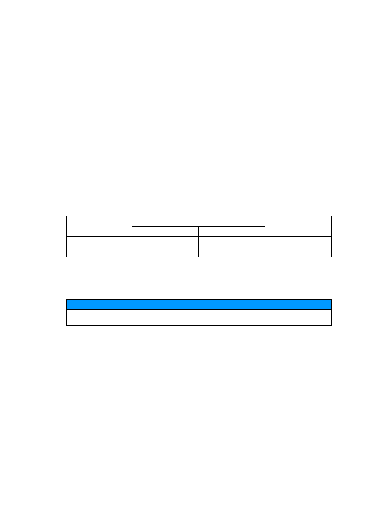
6.7.3 Linear Vibration Limits
Linear Vibration Levels As Measured On The Generator - P0/P1
Engine Speed Power Output Vibration Vibration Vibration
RPM S Displacement Velocity Acceleration
(min-1) (kVA) r.m.s. (mm) r.m.s. (mm/s) r.m.s. (mm/s2)
2000 ≤ RPM ≤ 3600 S ≤ 50 0.8 50 31
50 < S 0.64 40 25
1300 ≤ RPM < 2000 4 < S ≤ 50 0.64 40 25
50 < S ≤ 125 0.4 25 16
The broad band is taken as 10 Hz - 1000 Hz
16 A040J847 (Issue 4)

6.7.4 Linear Vibration Monitoring
We recommend using vibration analysing equipment to measure vibration. Check that
vibration of the generating set is below the limits stated in the standards. If vibration is above
the limits, the generating set builder should investigate the root causes and eliminate them.
Best practice is for the generating set builder to take initial readings as a reference and for
the user to periodically monitor vibration, according to the recommended service schedule,
to detect a deteriorating trend.
6.7.5 Excessive Vibration
WARNING
Excessive vibration can cause catastrophic failure of the generator, which could cause
personal injury.
If the measured vibration of the generating set is not within the limits:
1. The generating set manufacturer should change the generating set design to reduce
the vibration levels as much as possible.
2. Contact Cummins Generator Technologies to assess the impact on bearing and
generator life expectancy.
-
6.8 Bearings
6.8.1 Sealed Bearings
Sealed bearings are supplied pre-packed with grease and sealed for life. Sealed bearings do
not require re-greasing.
6.8.2 Bearing Life
Factors that reduce bearing life or lead to bearing failure include:
• Adverse operating conditions and environment
• Stress caused by misalignment of the generating set
• Vibration from the engine that exceeds the limits in BS 5000-3 and ISO 8528-9
• Long periods (including transportation) where the generator is stationary and subjected
to vibration can cause false brinelling wear (flats on the balls and grooves on the races)
• Very humid or wet conditions that cause corrosion and deterioration of the grease by
emulsification.
6.8.3 Health Monitoring of the Bearings
We recommend that the user checks the bearing condition, using vibration monitoring
equipment. Best practice is to take initial readings as a reference and periodically monitor
the bearings to detect a deteriorating trend. It will then be possible to plan a bearing change
at an appropriate generating set or engine service interval.
6.8.4 Bearing Service Life Expectancy
Bearing manufacturers recognise that service life of bearings depends on factors that are
outside their control: Rather than quote a service life, practicable replacement intervals are
based on the L10 life of the bearing, the type of grease and the recommendations of the
bearing and grease manufacturers.
A040J847 (Issue 4) 17

-
For general-purpose applications; if the correct maintenance is carried out, vibration levels
do not exceed the levels stated in ISO 8528-9 and BS5000-3, and the ambient temperature
does not exceed 50°C, plan to replace the bearings within 30,000 hours of operation.
If in doubt about any aspect of bearing life on STAMFORD generators, contact your nearest
supplier of STAMFORD generators or the Stamford factory.
18 A040J847 (Issue 4)
7 Installation into the Generating Set
7.1 Generator Dimensions
Dimensions are included in the data sheet specific to the generator model. Refer to the
rating plate to identify the generator model .
NOTICE
Data sheets are available from www.cumminsgeneratortechnologies.com
7.2 Lifting the Generator
CAUTION
The generator lifting points are designed to lift the generator only. Do not lift the complete
generating set (generator coupled to motive power source) by the generator lifting points.
Keep the generator horizontal when lifting. Fit the transit bar to single bearing generators to
keep the main rotor in the frame.
Lift the generator by shackle and pin attachment to the lifting points (lugs or eyes) provided.
A label attached to a lifting point shows the correct lifting arrangement. Use chains of
sufficient length, and a speader bar if necessary, to make sure that the chains are vertical
when lifting. Make sure that the capacity of the lifting equipment is sufficient for the
generator mass shown on the label.
FIGURE 3. LIFTING LABEL
7.3 Storage
If the generator is not to be used immediately, it must be stored in a clean, dry, vibration free
environment. We recommend the use of anti-condensation heaters.
Refer to Service and Maintenance section (Chapter 8) of this manual for further instructions
for the bearings of stored generators.
7.3.1 After Storage
After a period of storage, carry out ‘pre running checks’ to determine the condition of the
windings. If the winding are damp or the insulation is low, follow one of the ‘drying out
procedures’, in the Service and Maintenance section (Chapter 8) of this manual.
If the generator has been in storage for 12 months or more, replace the bearings.
A040J847 (Issue 4) 19
-
7.4 Vibration Frequencies
The main vibration frequencies produced by the generator are as follows:
• 4-pole 1500 RPM 25 Hz
• 4-pole 1800 RPM 30 Hz
• 2-pole 3000 RPM 50 Hz
• 2-pole 3600 RPM 60 Hz
Vibrations induced in the generator by the engine are complex. It is the responsibility of the
generating set designer to ensure that the alignment and stiffness of the bedplate and
mountings do not allow vibration to exceed BS5000 part 3 and ISO 8528 part 9 limits.
7.5 Side Loads
For belt-driven generators, make sure drive end and drive pulleys are aligned to avoid axial
load on the bearings. We recommend screw type tensioning devices to allow accurate
adjustment of belt tension whilst maintaining pulley alignment.
Belt and pulley guards must be provided by the generating set builder.
Important! Incorrect belt tensioning will result in excessive bearing wear.
2/4-Pole Side Load Shaft extension
Kg N
P0 92 900 82
P1 173 1700 82
7.6 Generating Set Coupling
NOTICE
Do not attempt to rotate the generator rotor by levering against the vanes of the cooling fan.
The fan is not designed to withstand such forces and will be damaged.
mm
Efficient operation and long component life depend on minimising mechanical stresses on
the generator. When coupled in a generating set, misalignment and vibration interactions
with the prime mover engine can cause mechanical stress.
20 A040J847 (Issue 4)

Generating sets need a substantial flat continuous bedplate to suit the installation site floor
loading, with engine and generator mounting pads to make a firm base for accurate
alignment. The height of all mounting pads must be within 0.25 mm for skid mounting, 3 mm
for non-adjustable anti-vibration mounts (AVM) or 10 mm for adjustable height AVMs. Use
shims to achieve level. The rotational axes of generator rotor and engine output shaft must
be coaxial (radial alignment) and perpendicular to the same plane (angular alignment). The
axial alignment of the generator and engine coupling must be within 0.5 mm, to allow for
thermal expansion without unwanted axial force on the bearings at operating temperature.
Vibration can occur by flexing of the coupling. The generator is designed for a maximum
bending moment not exceeding 17 kgm (125 lbs ft). Check the maximum bending moment
of the engine flange with the engine manufacturer.
Close-coupling of generator and engine can increase the rigidity of the generating set. Both
single and two bearing generators can be close-coupled. The generating set builder must
supply guarding for open-coupled applications.
To prevent rust during transit and storage, the generator frame spigot, rotor coupling plates
and shaft extension have been treated with a rust preventative coating. Remove this before
coupling the generating set.
To prevent movement of the rotor during transport, single bearing generators without an
excitation boost system (EBS) have a non-drive end (NDE) transit bracket fitted. Remove
the NDE cover, remove the NDE transit bracket and fastener from the rotor shaft, then refit
the NDE cover before coupling the generating set.
-
FIGURE 4. SINGLE BEARING GENERATOR ROTOR SHOWING COUPLING DISCS BOLTED TO
DRIVE END COUPLING HUB (AT RIGHT)
FIGURE 5. TWO BEARING GENERATOR ROTOR SHOWING SHAFT WITH KEYWAY FOR
FLEXIBLE COUPLING (AT RIGHT)
7.7 Single Bearing
1. If supplied, check that the bracket which supports the rotor underneath the fan hub is
fitted in position .
A040J847 (Issue 4) 21
 Loading...