


P0/P1 AC Generators
INSTALLATION, SERVICE AND
MAINTENANCE
English
Original Instructions
A040J847 (Issue 4)


Table of Contents
1. FOREWORD......................................................................................................................... 1
2. SAFETY PRECAUTIONS...................................................................................................... 3
3. SAFETY DIRECTIVES AND STANDARDS.......................................................................... 7
4. INTRODUCTION................................................................................................................... 9
5. AUTOMATIC VOLTAGE REGULATORS (AVR)................................................................. 13
6. APPLICATION OF THE GENERATOR............................................................................... 15
7. INSTALLATION INTO THE GENERATING SET................................................................ 19
8. SERVICE & MAINTENANCE.............................................................................................. 29
9. FAULT FINDING ................................................................................................................. 49
10. PARTS IDENTIFICATION................................................................................................... 67
11. TECHNICAL DATA.............................................................................................................. 71
12. SPARES AND AFTER SALES SERVICE........................................................................... 73
13. END OF LIFE DISPOSAL ................................................................................................... 75
A040J847 (Issue 4) i

-
This page is intentionally blank.
ii A040J847 (Issue 4)

1 Foreword
1.1 The Manual
This manual contains guidance and instructions for the installation, servicing and
maintenance of the generator.
Before operating the generator, read this manual and make sure that all personnel who work
on the equipment have access to the manual and all additional documentation supplied with
it. Misuse and failure to follow the instructions, and the use of non-approved parts, may
invalidate the product warranty and lead to potential accidents.
This manual is an essential part of the generator. Make sure that the manual is available to
all users throughout the life of the generator.
The manual is written for skilled electrical and mechanical technicians and engineers, who
have prior knowledge and experience of generating equipment of this type. If in doubt,
please seek expert advice or contact your local Cummins Generator Technologies
subsidiary.
Information in this manual was correct when published. It may be superseded due to our
policy of continuous improvement. Please visit www.cumminsgeneratortechnologies.com for
latest documentation.
NOTICE
A040J847 (Issue 4) 1

-
This page is intentionally blank.
2 A040J847 (Issue 4)
2 Safety Precautions
2.1 Safety Information and Notices used in this manual
Danger, Warning and Caution panels are used in this manual to describe the sources of
hazards, their consequences and how to avoid injury. Notice panels emphasise important or
critical instructions.
DANGER
Danger indicates a hazardous situation which, if not avoided, WILL result in death or serious
injury.
WARNING
Warning indicates a hazardous situation which, if not avoided, COULD result in death or
serious injury.
CAUTION
Caution indicates a hazardous situation which, if not avoided, COULD result in minor or
moderate injury.
NOTICE
Notice refers to a method or practice which can result in product damage, or to draw
attention to additional information or explanations.
2.2 Skill Requirements of Personnel
WARNING
Service and maintenance procedures should only be carried out by experienced and qualified
engineers, who are familiar with the procedures and the equipment.
2.3 Risk Assessment
WARNING
A risk assessment should be performed by the user/operating company to establish all
personnel-related risks. All affected users must be trained on the identified risks. Access to
the Power Plant/Generating Set during operation must be restricted to persons who have
been trained on these risks.
2.4 Personal Protective Equipment (PPE)
WARNING
All persons operating, servicing, maintaining or working in or with a power plant or a
generating set must wear appropriate Personal Protective Equipment (PPE).
A040J847 (Issue 4) 3

-
Recommended PPE includes:
• Ear and Eye Protection
• Head and face protection
• Safety footwear
• Overalls that protect the lower arms and legs
Ensure that all persons are fully aware of the emergency procedures in case of accidents.
2.5 Noise
Generators emit noise. Wear appropriate ear protection at all times. Maximum A-weighted
noise emissions may reach 97 dB(A). Contact the supplier for application-specific details.
2.6 Electrical Equipment
CAUTION
All electrical equipment can be dangerous if not operated correctly. Always install, service
and maintain the generator in accordance with this manual.
Work that requires access to electrical conductors must comply with all applicable local and
national electrical safety procedures for the voltages involved and any site specific rules.
Always use genuine branded replacement parts.
2.7 Lock Out/Tag Out
Isolate the generator from all sources of mechanical and electrical energy before starting
service or maintenance work. Adopt a suitable lock-out/tag out process.
2.8 Lifting
The lifting points provided are designed for lifting the generator only. Do not use the
generator lifting points to lift the complete generating set (generator coupled to motive power
source).
Do not remove the lifting label attached to one of the lifting points.
CAUTION
WARNING
WARNING
2.9 Generator Operating Areas
WARNING
In the event of catastrophic failure, machine parts may be ejected from the generator air
inlet/outlet (shaded regions of diagram). Do not place controls near the air inlet/outlet and
restrict personnel from these regions during machine running.
4 A040J847 (Issue 4)

2.10 Hazard Warning Labels
Hazard warning labels are fixed to the generator. If the original labels are missing, damaged
or painted over, replace them with the spare set supplied in a wallet attached to the
generator. Label locations are shown on the back of the label set.
-
2.11 General Guidance
NOTICE
These safety precautions are for general guidance and supplement your own safety
procedures and all applicable laws and standards.
A040J847 (Issue 4) 5

-
This page is intentionally blank.
6 A040J847 (Issue 4)

3 Safety Directives and Standards
STAMFORD AC generators meet applicable European safety directives, and national and
international standards relevant to generators. The generator must be operated within the
limits specified in the relevant standards and within the parameters on the generator rating
plate.
Marine generators meet the requirements of all the major marine classification societies.
3.1 European Directives: EC Declaration of Conformity for Incorporation
Each generator supplied in the European Economic Area (EEA) is supplied with an EC
Declaration of Conformity for Incorporation into an electricity generating set. It is the
responsibility of the generating set manufacturer to ensure that the complete generating set
complies with EC Directives and standards.
Our authorized representative in the European Community is Mr Jeffrey Matthews,
Engineering Director, Cummins Generator Technologies Ltd.
All generators meet the following Standards and Directives:
Directives:
• 2004/108/EC EMC Directive
• 2006/95/EC Low Voltage Directive
• 2006/42/EC Machinery Directive
Standards:
• EN 61000-6-1 Electromagnetic Compatibility, Generic Standards - Immunity for
residential, commercial and light-industrial environments
• EN 61000-6-2 Electromagnetic Compatibility, Generic Standards - Immunity for
industrial environments
A040J847 (Issue 4) 7

-
• EN 61000-6-4 Electromagnetic Compatibility, Generic Standards - Emission standard
for light-industrial environments
• EN ISO 12100-1 Safety of Machinery, Basic concepts, general principles for design Basic terminology, methodology
• EN ISO 12100-2 Safety of Machinery, Basic concepts, general principles for design Technical principles
• EN ISO 14121-1 Safety of Machinery, Risk assessment - Principles
• EN 60034-1 Rotating electrical machines - Rating and performance
• BS ISO 8528-3 Reciprocating internal combustion engine driven alternating current
generating sets - alternating current generators for generating sets
• BS 5000-3 Rotating electrical machines - Generators to be driven by reciprocating
internal combustion engines - Requirements for resistance to vibration
NOTICE
Once the generator is built into a generating set, it is the responsibility of the generating set
manufacturer to ensure that the generating set complies with the relevant specifications and
standards.
3.2 Additional Information for EMC Compliance
STAMFORD generators are designed to meet EMC emissions and immunity standards for
industrial environments. Document reference N4/X/011 outlines additional equipment that
may be required when the generator is installed in residential, commercial and light industrial
environments.
The installation ‘earth/ground’ arrangements require the connection of the generator frame to
the site protective earth conductor using a minimum lead length.
Installation, maintenance and servicing must be carried out by adequately trained personnel
fully aware of the requirements of the relevant EC directives.
NOTICE
Cummins Generator Technologies is not liable for EMC compliance if unauthorised parts, not
of STAMFORD brand, are used for maintenance and servicing.
3.3 Additional Information for CSA Compliance
To comply with Canadian Standards Association (CSA) regulations, all external wiring and
components must be rated at the generator rated voltage shown on the rating plate label.
8 A040J847 (Issue 4)

4 Introduction
4.1 General Description
P0/P1 generators are of brushless rotating field design, available up to 600V, 50Hz (1500
RPM, 4 pole and 3000 RPM, 2 pole) or 60Hz (1800 RPM, 4 pole and 3600 RPM, 2 pole),
and built to meet B.S. 5000 Part 3 and other international standards.
P0/P1 are self-excited, with excitation power derived from the main output windings using
the AS480 AVR.
4.2 Serial Number Location
A unique serial number is stamped into the top of the generator frame near the drive end
and shown on the rating plate and tracking labels on the side of the generator frame.
4.3 Rating Plate
The fixed rating plate label states the intended operating parameters of the generator.
The generator could overheat if operated outside the parameters specified on the rating plate.
Overheating can cause catastrophic failure and injury from ejected debris. Always operate
the generator within the rated parameters.
WARNING
4.4 Product Authentication
The STAMFORD high security, anti-counterfeit hologram is located on the Tracking
Label. Check that the dots are visible around the STAMFORD logo when viewing the
hologram from different angles and the word "GENUINE" appears behind the logo. Use a
flashlight to see these security features in low ambient light. Check that the generator is
genuine by entering the unique 7 character hologram code at www.stamford-
avk.com/verify.
FIGURE 1. GLOBAL STAMFORD AC GENERATOR NAMEPLATE, COMPRISING RATING PLATE
(ABOVE) AND TRACKING LABEL (BELOW)
A040J847 (Issue 4) 9

-
FIGURE 2. DOTS VISIBLE IN LEFT, RIGHT, UPPER AND LOWER VIEWS OF 3D HOLOGRAM
10 A040J847 (Issue 4)
4.5 Self-Excited AVR Controlled Generators
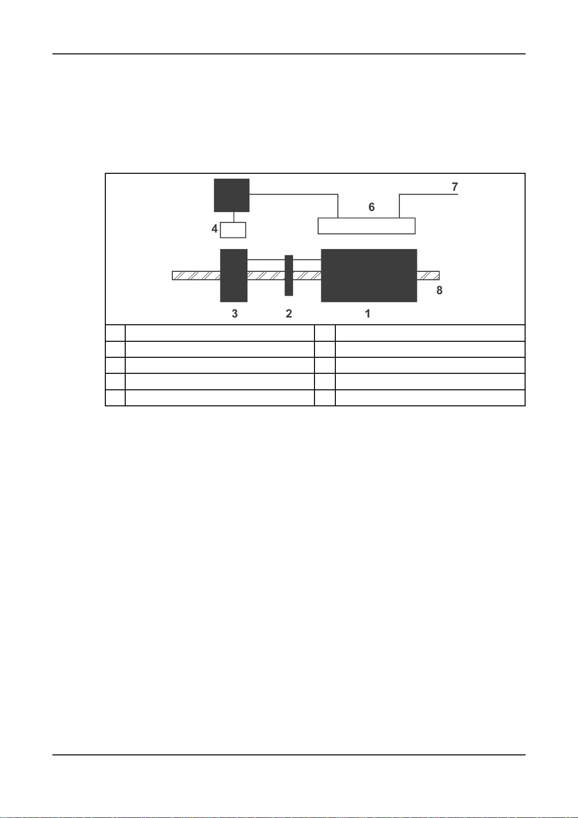
4.5.1 Main Stator Powered AVR
The AVR provides closed loop control by sensing the generator output voltage at the main
stator windings and applying voltage to the exciter stator. Voltage induced in the exciter
rotor, rectified by the rotating diodes, magnetises the main rotor which induces voltage in the
main stator windings. The AVR is also powered by the main stator.
-
No. Description No. Description
1 Main rotor 5 AVR
2 Rotating diodes 6 Main stator
3 Exciter rotor 7 Output
4 Exciter stator 8 Shaft
4.6 Separately-Excited AVR Controlled Generators
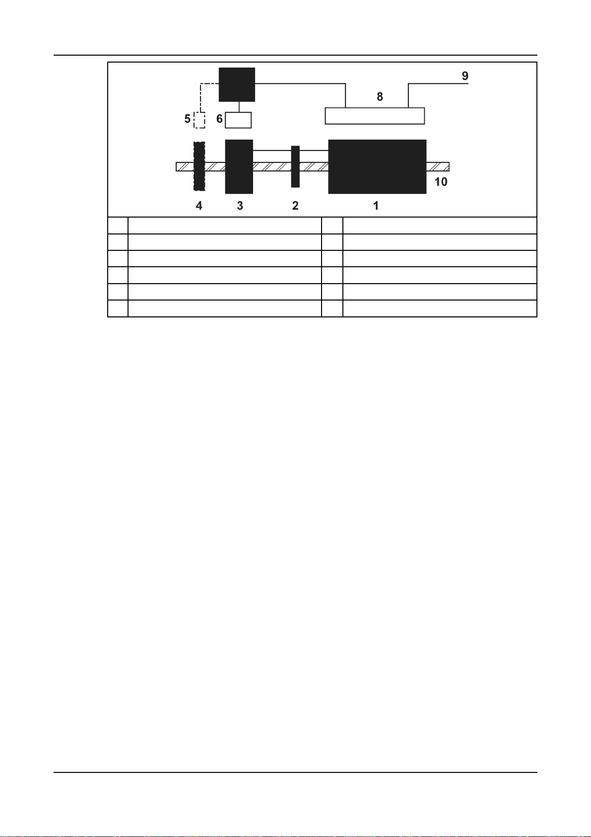
4.6.1 Excitation Boost System (EBS)
The EBS is a self-contained optional unit, attached to the non-drive end of the generator.
The EBS unit consists of the Excitation Boost Controller (EBC) and an Excitation Boost
Generator (EBG). Under fault conditions, or when the generator is subjected to a large
impact load such as a motor starting, the generator voltage drops. The EBC senses the drop
in voltage and engages the output power of the EBG. This additional power feeds the
generator’s excitation system, supporting the load until the generator voltage recovers or
breaker discrimination removes the fault.
A040J847 (Issue 4) 11
-
No. Description No. Description
1 Main rotor 6 Exciter stator
2 Rotating diodes 7 AVR & EBS
3 Exciter rotor 8 Main stator
4 EBG rotor (optional) 9 Output
5 EBG stator (optional) 10 Shaft
12 A040J847 (Issue 4)

5 Automatic Voltage Regulators (AVR)
Cummins Generator Technologies offer a selection of Automatic Voltage Regulators (AVRs)
designed and built to achieve maximum performance from the range of STAMFORD
brushless AC generators. Self-excited and separately-excited types are available, from lowcost analogue to sophisticated digital control. All STAMFORD AVRs are encapsulated to
provide environmental protection, and are mounted on anti-vibration mounts for added
mechanical protection.
All STAMFORD AVRs have the following features:
• connections to a remote hand trimmer accessory for fine control of the generator output
voltage
• ‘Under-Frequency Roll-Off’ (UFRO) protection to reduce the generator output voltage if
speed falls below a threshold, and
• connections to power factor and droop accessories for sharing reactive load in parallel
with other generators or mains utility.
AVR specification, installation and adjustment information is available in the AVR manual
supplied with the generator, or at www.cumminsgeneratortechnologies.com
NOTICE
AVR analogue inputs must be fully floating (galvanically isolated from ground), with
an insulation strength of 500 V a.c.
5.1 Self-Excited
A self-excited AVR receives power from the generator output terminals. The AVR controls
the generator output voltage by automatic adjustment of the exciter stator field strength.
5.1.1 AS480
The AS480 achieves voltage regulation of ±1.0%. The design employs surface mount
technology, custom mouldings and heatsink in a compact assembly.
The AVR includes the following extra features:
• connections to an Excitation Boost System accessory, and
• connection of a lead assembly for low voltage (100 V to 120 V a.c.) sensing.
5.2 AVR Accessories
Accessories to support AVR functions are factory-fitted or supplied separately with
instructions for fitting and wiring by a competent technician.
5.2.1 Hand Trimmer (for remote voltage adjustment)
A hand trimmer can be fitted in a convenient position (typically in the generator set control
panel) and connected to the AVR to provide fine adjustment of the generator voltage. The
hand trimmer value and the adjustment range obtained is as defined in the Technical
Specification. Refer to wiring diagram before removing the shorting link and connecting the
hand trimmer.
A040J847 (Issue 4) 13

-
5.2.2 Droop Transformer (for parallel operation – generator to generator)
A droop transformer can be fitted in a defined position in the generator main output wiring
and connected to the AVR to enable parallel operation with other generators. The
adjustment range is as defined in the Technical Specification. Refer to wiring diagram before
removing the shorting link and connecting the droop transformer. The droop transformer
MUST be connected in the correct main output terminal for proper operation (details are as
shown in the machine wiring diagram).
5.2.3 Excitation Boost System (with AS480 AVR only)
An add-on pilot winding and permanent-magnet rotor assembly is available to enhance the
motor-starting and overload performance of the AS480 AVR. This is fitted to the non-driveend bracket of the generator as a single integrated assembly and connects into the AVR via
four ‘faston’ connections. During motor-starting or other heavy overloads the unit
automatically provides additional excitation support as demanded by the AVR. An internal
over-excitation system prevents prolonged overload from damaging the generator.
5.2.4 Low Voltage Link/Selector
The AS480 AVR can be configured for low voltage working between 100 V a.c. and 120 V
a.c. with a special lead assembly which connects between the generator main terminals and
AVR input terminal ‘S1’. In low-voltage operating mode the overload performance of the
control system is reduced. The EBS will not work at low voltage.
14 A040J847 (Issue 4)
6 Application of the Generator
It is the customer's responsibility to make sure that the selected generator is suitable for the
final application.
CAUTION
Overloading a generator may lead to catastrophic failure.
6.1 Environment
STAMFORD generators are protected to IP23 as standard. IP23 is not adequate protection
for use outdoors without additional measures.
Ambient Temperature -15 °C to 40 °C
Relative Humidity < 60%
Altitude < 1000 m
The generator has been designed for the environment shown in the table. The generator can
operate outside these conditions if it is rated accordingly: The nameplate gives details. If the
operating environment is changed after purchase, refer to the factory for a revised generator
rating.
6.2 Air Flow
Make sure that the air inlets and outlets are not obstructed when the generator is running.
6.3 Airborne Contaminants
Contaminants such as salt, oil, exhaust fumes, chemicals, dust and sand will reduce the
effectiveness of the insulation and the life of the windings. Consider using air filters and an
enclosure to protect the generator.
6.4 Humid Conditions
The water carrying capacity of air depends on temperature. If the air temperature falls below
its saturation point, dew may form on the windings reducing the electrical resistance of the
insulation. In humid conditions additional protection may be required, even if the generator is
fitted inside an enclosure. Anti-condensation heaters are supplied on request.
6.5 Anti-condensation heaters
WARNING
Power to the anti-condensation heater is supplied from a separate source. Before
doing any work on the heater, make sure the power is isolated and locked off.
Anti-condensation heaters raise the air temperature around the windings to deter
condensation forming in humid conditions when the generator is not operating. Best practice
is to energise the heaters automatically when the generator is off.
A040J847 (Issue 4) 15

-
6.6 Enclosures
Fit an enclosure to protect the generator from adverse environmental conditions. Make sure
that air entering the generator is of adequate flowrate, free from moisture and contaminants,
and below the maximum ambient temperature on the rating plate.
Make sure there is sufficient access around the generator for safe maintenance.
P0 and P1 generators have round end brackets that will create an air flow pattern that differs
from previous generators of this size. The air flow should be modeled to identify and prevent
hot air from recirculating within the enclosure.
6.7 Vibration
STAMFORD generators are designed to withstand the vibration levels encountered on
generating sets built to meet the requirements of ISO 8528-9 and BS 5000-3. (Where ISO
8528 is taken to be broad band measurements and BS5000 refers to the predominant
frequency of any vibrations on the generating set).
Exceeding either of the above specifications will have a detrimental effect on the life of the
bearings and other components, and may invalidate the generator warranty.
NOTICE
6.7.1 Definition of BS5000–3
Generators shall be capable of continuously withstanding linear vibration levels with
amplitudes of 0.25mm between 5Hz and 8Hz and velocities of 9.0mm/s r.m.s. between 8 Hz
and 200 Hz, when measured at any point directly on the carcass or main frame of the
machine. These limits refer only to the predominant frequency of vibration of any complex
waveform.
6.7.2 Definition of ISO 8528-9
ISO 8528-9 refers to a broad band of frequencies; the broad band is taken to be between 10
Hertz and 1000 Hertz. The table below is an extract from ISO 8528-9 (Table C.1, value 1).
This simplified table lists the vibration limits by kVA and speed for acceptable operation of
standard generating set designs.
6.7.3 Linear Vibration Limits
Linear Vibration Levels As Measured On The Generator - P0/P1
Engine Speed Power Output Vibration Vibration Vibration
RPM S Displacement Velocity Acceleration
(min-1) (kVA) r.m.s. (mm) r.m.s. (mm/s) r.m.s. (mm/s2)
2000 ≤ RPM ≤ 3600 S ≤ 50 0.8 50 31
50 < S 0.64 40 25
1300 ≤ RPM < 2000 4 < S ≤ 50 0.64 40 25
50 < S ≤ 125 0.4 25 16
The broad band is taken as 10 Hz - 1000 Hz
16 A040J847 (Issue 4)

6.7.4 Linear Vibration Monitoring
We recommend using vibration analysing equipment to measure vibration. Check that
vibration of the generating set is below the limits stated in the standards. If vibration is above
the limits, the generating set builder should investigate the root causes and eliminate them.
Best practice is for the generating set builder to take initial readings as a reference and for
the user to periodically monitor vibration, according to the recommended service schedule,
to detect a deteriorating trend.
6.7.5 Excessive Vibration
WARNING
Excessive vibration can cause catastrophic failure of the generator, which could cause
personal injury.
If the measured vibration of the generating set is not within the limits:
1. The generating set manufacturer should change the generating set design to reduce
the vibration levels as much as possible.
2. Contact Cummins Generator Technologies to assess the impact on bearing and
generator life expectancy.
-
6.8 Bearings
6.8.1 Sealed Bearings
Sealed bearings are supplied pre-packed with grease and sealed for life. Sealed bearings do
not require re-greasing.
6.8.2 Bearing Life
Factors that reduce bearing life or lead to bearing failure include:
• Adverse operating conditions and environment
• Stress caused by misalignment of the generating set
• Vibration from the engine that exceeds the limits in BS 5000-3 and ISO 8528-9
• Long periods (including transportation) where the generator is stationary and subjected
to vibration can cause false brinelling wear (flats on the balls and grooves on the races)
• Very humid or wet conditions that cause corrosion and deterioration of the grease by
emulsification.
6.8.3 Health Monitoring of the Bearings
We recommend that the user checks the bearing condition, using vibration monitoring
equipment. Best practice is to take initial readings as a reference and periodically monitor
the bearings to detect a deteriorating trend. It will then be possible to plan a bearing change
at an appropriate generating set or engine service interval.
6.8.4 Bearing Service Life Expectancy
Bearing manufacturers recognise that service life of bearings depends on factors that are
outside their control: Rather than quote a service life, practicable replacement intervals are
based on the L10 life of the bearing, the type of grease and the recommendations of the
bearing and grease manufacturers.
A040J847 (Issue 4) 17

-
For general-purpose applications; if the correct maintenance is carried out, vibration levels
do not exceed the levels stated in ISO 8528-9 and BS5000-3, and the ambient temperature
does not exceed 50°C, plan to replace the bearings within 30,000 hours of operation.
If in doubt about any aspect of bearing life on STAMFORD generators, contact your nearest
supplier of STAMFORD generators or the Stamford factory.
18 A040J847 (Issue 4)
7 Installation into the Generating Set
7.1 Generator Dimensions
Dimensions are included in the data sheet specific to the generator model. Refer to the
rating plate to identify the generator model .
NOTICE
Data sheets are available from www.cumminsgeneratortechnologies.com
7.2 Lifting the Generator
CAUTION
The generator lifting points are designed to lift the generator only. Do not lift the complete
generating set (generator coupled to motive power source) by the generator lifting points.
Keep the generator horizontal when lifting. Fit the transit bar to single bearing generators to
keep the main rotor in the frame.
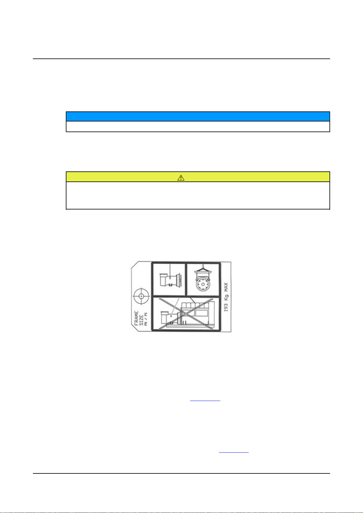
Lift the generator by shackle and pin attachment to the lifting points (lugs or eyes) provided.
A label attached to a lifting point shows the correct lifting arrangement. Use chains of
sufficient length, and a speader bar if necessary, to make sure that the chains are vertical
when lifting. Make sure that the capacity of the lifting equipment is sufficient for the
generator mass shown on the label.
FIGURE 3. LIFTING LABEL
7.3 Storage
If the generator is not to be used immediately, it must be stored in a clean, dry, vibration free
environment. We recommend the use of anti-condensation heaters.
Refer to Service and Maintenance section (Chapter 8) of this manual for further instructions
for the bearings of stored generators.
7.3.1 After Storage
After a period of storage, carry out ‘pre running checks’ to determine the condition of the
windings. If the winding are damp or the insulation is low, follow one of the ‘drying out
procedures’, in the Service and Maintenance section (Chapter 8) of this manual.
If the generator has been in storage for 12 months or more, replace the bearings.
A040J847 (Issue 4) 19
-
7.4 Vibration Frequencies
The main vibration frequencies produced by the generator are as follows:
• 4-pole 1500 RPM 25 Hz
• 4-pole 1800 RPM 30 Hz
• 2-pole 3000 RPM 50 Hz
• 2-pole 3600 RPM 60 Hz
Vibrations induced in the generator by the engine are complex. It is the responsibility of the
generating set designer to ensure that the alignment and stiffness of the bedplate and
mountings do not allow vibration to exceed BS5000 part 3 and ISO 8528 part 9 limits.
7.5 Side Loads
For belt-driven generators, make sure drive end and drive pulleys are aligned to avoid axial
load on the bearings. We recommend screw type tensioning devices to allow accurate
adjustment of belt tension whilst maintaining pulley alignment.
Belt and pulley guards must be provided by the generating set builder.
Important! Incorrect belt tensioning will result in excessive bearing wear.
2/4-Pole Side Load Shaft extension
Kg N
P0 92 900 82
P1 173 1700 82
7.6 Generating Set Coupling
NOTICE
Do not attempt to rotate the generator rotor by levering against the vanes of the cooling fan.
The fan is not designed to withstand such forces and will be damaged.
mm
Efficient operation and long component life depend on minimising mechanical stresses on
the generator. When coupled in a generating set, misalignment and vibration interactions
with the prime mover engine can cause mechanical stress.
20 A040J847 (Issue 4)

Generating sets need a substantial flat continuous bedplate to suit the installation site floor
loading, with engine and generator mounting pads to make a firm base for accurate
alignment. The height of all mounting pads must be within 0.25 mm for skid mounting, 3 mm
for non-adjustable anti-vibration mounts (AVM) or 10 mm for adjustable height AVMs. Use
shims to achieve level. The rotational axes of generator rotor and engine output shaft must
be coaxial (radial alignment) and perpendicular to the same plane (angular alignment). The
axial alignment of the generator and engine coupling must be within 0.5 mm, to allow for
thermal expansion without unwanted axial force on the bearings at operating temperature.
Vibration can occur by flexing of the coupling. The generator is designed for a maximum
bending moment not exceeding 17 kgm (125 lbs ft). Check the maximum bending moment
of the engine flange with the engine manufacturer.
Close-coupling of generator and engine can increase the rigidity of the generating set. Both
single and two bearing generators can be close-coupled. The generating set builder must
supply guarding for open-coupled applications.
To prevent rust during transit and storage, the generator frame spigot, rotor coupling plates
and shaft extension have been treated with a rust preventative coating. Remove this before
coupling the generating set.
To prevent movement of the rotor during transport, single bearing generators without an
excitation boost system (EBS) have a non-drive end (NDE) transit bracket fitted. Remove
the NDE cover, remove the NDE transit bracket and fastener from the rotor shaft, then refit
the NDE cover before coupling the generating set.
-
FIGURE 4. SINGLE BEARING GENERATOR ROTOR SHOWING COUPLING DISCS BOLTED TO
DRIVE END COUPLING HUB (AT RIGHT)
FIGURE 5. TWO BEARING GENERATOR ROTOR SHOWING SHAFT WITH KEYWAY FOR
FLEXIBLE COUPLING (AT RIGHT)
7.7 Single Bearing
1. If supplied, check that the bracket which supports the rotor underneath the fan hub is
fitted in position .
A040J847 (Issue 4) 21

-
2. Position the generator close to the engine and remove the drive end transit bracket that
keeps the rotor in place during transport.
CAUTION
Keep the generator horizontal to keep the rotor in place
3. Remove the air outlet covers from the drive end of the generator to access the coupling
and adaptor bolts.
4. If required, tighten the coupling disc bolts in the sequence shown above.
5. Check the torque of bolts that fasten the coupling discs to the DE coupling hub in a
clockwise direction around the bolt circle.
6. Make sure the coupling discs are concentric with the adaptor spigot. Use alignment
studs to ensure that the disc and the flywheel are in alignment.
7. Make sure the axial distance from the coupling mating face on the flywheel to the
mating face on the flywheel housing is within 0.5mm of nominal dimension. This
ensures that the engine crankshaft float is maintained and the generator rotor position
is neutral, allowing for thermal expansion. There is no axial pre-load thrust on the
engine or generator bearings.
8. Offer the generator to the engine and engage coupling discs and housing spigots at the
same time, pushing the generator towards the engine until the coupling discs are
against the flywheel face and the housing spigots are located.
CAUTION
Do not pull the generator to the engine using bolts through the flexible discs.
CAUTION
Failure to secure bolts can lead to excessive vibration, which in turn can lead to
catastrophic generator failure.
9. Fit heavy gauge washers under the heads of housing and coupling bolts. Screw in the
bolts evenly around the coupling assembly to maintain correct alignment.
22 A040J847 (Issue 4)

10. Tighten the bolts to fix the coupling disc to the flywheel, in the sequence shown above.
11. Check the torque of each bolt in a clockwise direction around the bolt circle to ensure
all the bolts are tight. Refer to the engine manufacturer’s manual for correct tightening
torque.
12. If a PMG is not fitted, remove the NDE transit bracket.
13. Replace all covers.
-
7.8 Two Bearing
A flexible coupling, designed to suit the specific engine/generator combination, is
recommended to minimise torsional vibration effects.
If a close coupling adaptor is used the alignment of machined faces must be checked by
offering the generator up to the engine. Shim the generator feet if necessary.
7.9 Pre-Running Checks
Before starting the generating set, test the insulation resistance of windings, check all
connections are tight and in the correct location. Ensure the generator air path is clear of
obstructions. Replace all covers.
7.10 Insulation Resistance Test
NOTICE
Disconnect the AVR and voltage transformers (if fitted) before this test. Disconnect and earth
all RTD and Thermistor temperature sensors (if fitted) before this test.
The resistance test must be carried out by a qualified person.
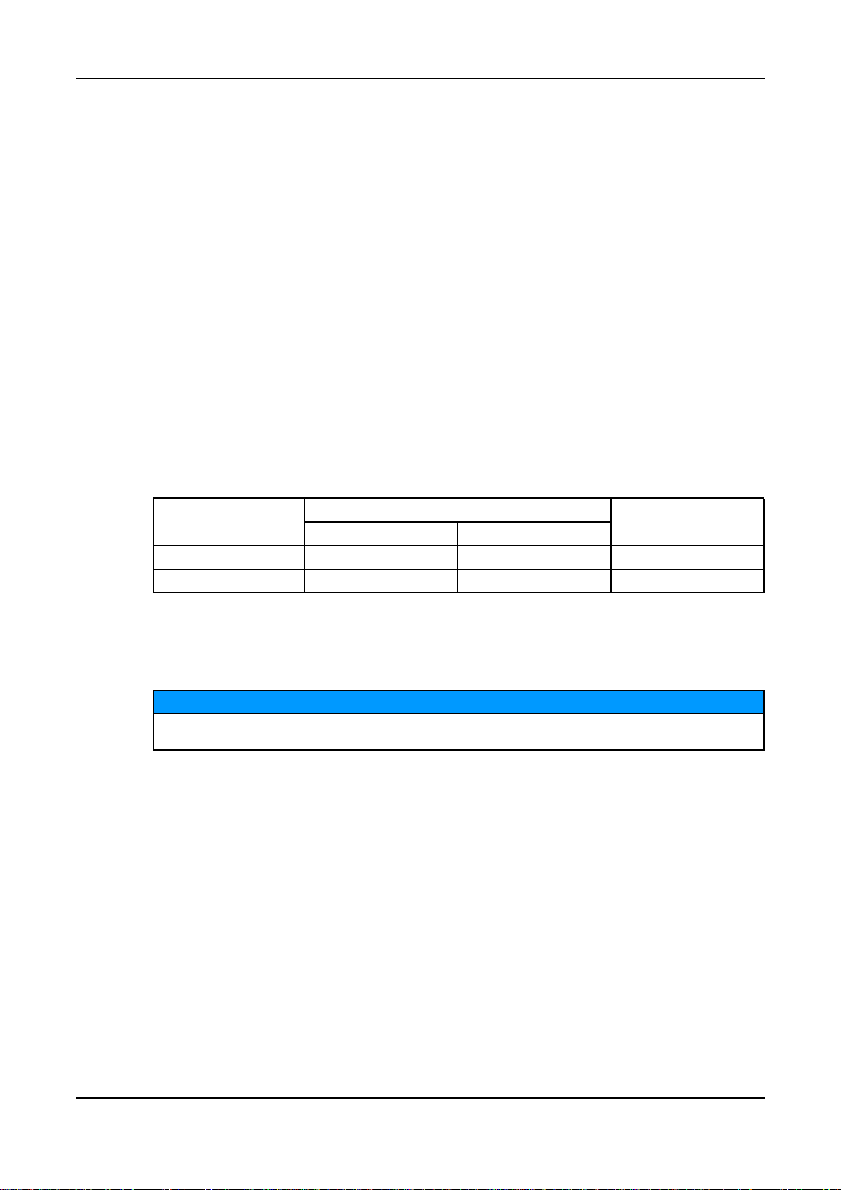
Generator Voltage Test Voltage (V) Minimum Insulation Resistance (MΩ)
You must dry out the generator windings if the measured insulation resistance is less than
the minimum value. See the Service & Maintenance section (Chapter 8) of this manual.
A040J847 (Issue 4) 23
(kV)
Up to 1 500 5 10
In Service Generator New Generator

-
7.10.1 High Voltage Test
Windings have been tested at high voltage during manufacture. Repeated high voltage tests
may degrade the insulation and reduce operating life. If a further test is required at
installation for customer acceptance, it must be done at a reduced voltage, V = 0.8 x (2 x
Rated Voltage + 1000). Once in service, any further tests for maintenance purposes must be
done after passing visual checks and insulation resistance tests, and at a reduced voltage, V
= (1.5 x Rated Voltage).
7.11 Direction of Rotation
The fan is designed for clockwise rotation, as viewed from the drive end of the generator
(unless otherwise specified when ordered). If the generator must run counter-clockwise,
please seek advice from Cummins Generator Technologies .
NOTICE
7.12 Phase Rotation
Main stator output is connected for a phase sequence of U V W when the generator runs
clockwise, as viewed from the drive end. If the phase rotation must be reversed, the
customer must re-connect the output cables in the terminal box. Ask Cummins Generator
Technologies for a circuit diagram of ‘reverse phase connections’.
7.13 Voltage and Frequency
Check that the voltage and frequency shown on the generator rating plate meet the
requirements of the generating set application.
24 A040J847 (Issue 4)

7.14 AVR Settings
The AVR is factory set for initial running tests. Check that the AVR settings are compatible
with your required output. Refer to detailed instructions in the AVR manual for on- and offload adjustments.
7.15 Electrical Connections
Incorrect electrical installation and system protection can cause personal injury. Installers
must be qualified to perform electrical installation work and are responsible for meeting the
requirements of any inspectorate, local electricity authority and site safety rules.
Fault current curves and generator reactance values are available on request from the
factory so that the system designer can calculate the necessary fault protection and/or
discrimination.
The installer must check that the generator frame is bonded to the generating set bedplate,
and must bond to site earth. If anti-vibration mounts are fitted between the generator frame
and its bedplate, a suitably-rated earth conductor must bridge across the anti-vibration
mount.
-
WARNING
Refer to wiring diagrams for electrical connection of the load cables. Electrical connections
are made in the terminal box. Route single core cables through the insulated or nonmagnetic gland plates supplied. Panels must be removed to be drilled or cut to prevent
swarf entering the terminal box or generator. After wiring, inspect the terminal box, remove
all debris using a vacuum cleaner if necessary and check that no internal components are
damaged or disturbed.
As standard, the generator neutral is not bonded to the generator frame. If required, neutral
may be connected to the earth terminal in the terminal box, by a conductor of at least one
half of the sectional area of a phase lead.
Load cables must be supported appropriately to avoid a tight radius at the point of entry into
the terminal box, clamped at the terminal box gland, and allow at least ±25 mm movement
by the generator set on its anti-vibration mountings, without causing excessive stress to the
cables and generator load terminals.
The palm (flattened part) of load cable lugs must be clamped in direct contact with the main
stator output conductors so that the whole palm area conducts the output current. The
tightening torque of fasteners is 6 to 6.6 Nm.
A040J847 (Issue 4) 25

-
7.16 Synchronisation
7.16.1 Parallel or Synchronising AC Generators
FIGURE 6. PARALLEL OR SYNCHRONISING AC GENERATORS
The quadrature droop current transformer (Droop CT) gives a signal proportional to reactive
current; the AVR adjusts excitation to reduce circulating current and allow each generator to
share reactive load. A factory-fitted droop CT is pre-set for 5% voltage drop at full-load zero
power factor. Refer to the supplied AVR manual for droop adjustment.
• The synchronising switch/breaker (CB1, CB2) must be of a type that will not cause
“contact bounce” when it operates.
• The synchronising switch/breaker must be adequately rated to withstand the
continuous full load current of the generator.
• The switch/breaker must be able to withstanding the rigorous closing cycles during
synchronising and the currents produced if the generator is parallelled out of
synchronism.
• The closing time of the synchronising switch/breaker must be under the control of the
synchroniser settings.
• The switch/breaker must be capable of operation under fault conditions such as short
circuits. Generator data sheets are available.
NOTICE
The fault level may include a contribution from other generators as well as from the
grid/mains utility.
The method of synchronising should be either automatic, or by check synchronising. The
use of manual synchronising is not recommended. The settings on the synchronising
equipment should be such that the generator will close smoothly.
CAUTION
Synchronising outside the following parameters may result in catastrophic failure of the
generator.
The Phase sequence must match
Voltage difference +/- 0.5%
Frequency difference 0.1 Hz/sec
Phase angle +/- 10
C/B closing time 50 ms
o
The settings for the synchronising equipment to achieve this must be within these
parameters.
26 A040J847 (Issue 4)

The voltage difference when paralleling with the grid/mains utility is +/- 3% .
-
A040J847 (Issue 4) 27

-
This page is intentionally blank.
28 A040J847 (Issue 4)

8 Service & Maintenance
8.1 Recommended Service Schedule
Refer to Safety Precautions section (Chapter 2) of this manual before starting any service
and maintenance activity.
Refer to Parts Identification section (Chapter 10) for an exploded view of components and
fastener information.
The recommended service schedule shows the recommended service activities in table
rows, grouped by generator subsystem. Columns of the table show the types of service
activity, whether the generator must be running, and the service levels. Service frequency is
given in running hours or time interval, whichever is sooner. A cross (X) in the cells where a
row intersects the columns shows a service activity type and when it is required. An asterisk
(*) shows a service activity done only when necessary.
All service levels in the recommended service schedule can be purchased directly from
Cummins Generator Technologies Customer Service Department,
Telephone: +44 1780 484732,
Email: service-engineers@cumminsgeneratortechnologies.com
A040J847 (Issue 4) 29

-
TABLE 1. RECOMMENDED SERVICE SCHEDULE
SERVICE ACTIVITY TYPE SERVICE LEVEL
X = required
System
* = if necessary
Generator rating X X
Bedplate arrangement X X
Coupling arrangement X X * X
Environmental
conditions and X X X X X X
cleanliness
Ambient temperature
(inside & outside)
Complete machine damage, loose parts & X X X X X X
earth bonds
Generator
Guards, screens,
warning and safety X X X X X X
labels
Maintenance access X X
Electrical nominal
operating conditions & X X X X X X X
excitation
Vibration X X X X X X X
Condition of windings X X X X X X
Insulation resistance of
all windings (PI test for X X * * X X
MV/HV)
Insulation resistance of
rotor, exciter and PMG
Windings
Temperature sensors X X X X X X X
Customer settings for
temperature sensors
Condition of bearings X X X
Bearing(s) X * X
Temperature sensors X X X X X X X
Bearings
Customer settings for
temperature sensors
All generator/customer
connections and
cabling
Generator running
Inspect
Test
Clean
Replace
Commission
Post Commission
250 hrs / 0.5 year
Level 1
1000 hrs / 1 year
Level 2
X X X X X X
X X X
X X
X X
X X X X X X
10,000 hrs / 2 years
Level 3
30,000 hrs / 5 years
Terminal Box
30 A040J847 (Issue 4)

SERVICE ACTIVITY TYPE SERVICE LEVEL
X = required
System
* = if necessary
Initial AVR & PFC set
up
AVR & PFC settings X X X X X X
Customer connection of
auxiliaries
Function of auxiliaries X X X X X X
Synchronisation
settings
Synchronisation X X X X X X X
Controls & Auxiliaries
Anti condensation
heater
Diodes and varistors X X X X X
Diodes and varistors
Rectifier
Generator running
Inspect
Test
Clean
Replace
X X X
X X X X X
X X
X * X
X X
Commission
Post Commission
250 hrs / 0.5 year
Level 1
1000 hrs / 1 year
Level 2
10,000 hrs / 2 years
-
Level 3
30,000 hrs / 5 years
Air inlet temperature X X X X X X X
Air flow (rate &
direction)
Condition of fan X X X X X X
Cooling
Condition of air filter
(where fitted)
Air filters (where fitted) X X * * *
X X X
X X X X X X
1. Proper service and repair are vital to the reliable operation of your generator and the
safety of anyone coming into contact with the generator.
2. These service activities are intended to maximise the life of the generator but shall not
vary, extend or change the terms of the manufacturer's standard warranty or your
obligations in that warranty.
3. Each service interval is a guide only, and developed on the basis that the generator
was installed and is operated in accordance with the manufacturer's guidelines. If the
generator is located and/or operated in adverse or unusual environmental conditions,
the service intervals may need to be more frequent. The generator should be
continually monitored between services to identify any potential failure modes, signs of
misuse, or excessive wear and tear.
A040J847 (Issue 4) 31

-
8.2 Bearings
8.2.1 Introduction
The generator rotor is supported by a bearing at the non-drive end (NDE) and by either a
bearing or a coupling to the prime mover at the drive end (DE). If possible, turn the rotor of
an out of service generator at least six revolutions every month to lubricate the bearing
surfaces with grease and re-position the rotating elements to avoid false brinelling. If rotation
is not possible and the storage period is over two years, replace the bearings before putting
the generator into service
8.2.2 Safety
Safety guards must be removed to replace bearings. To prevent injury, isolate the generating
set from all energy sources and remove stored energy. Use lock and tag safety procedures
before starting work.
External surfaces may be very hot. Exposed skin can suffer serious and permanent burns,
depending on the temperature and contact time. Avoid contact or wear protective gloves.
DANGER
WARNING
Store removed parts and tools in static- and dust-free conditions, to prevent damage or
contamination.
A bearing is damaged by the axial force needed to remove it from the rotor shaft. Do not
reuse a bearing.
A bearing is damaged if the insertion force is applied through the bearing balls. Do not press
fit the outer race by force on the inner race, or vice versa.
Do not try to turn the rotor by levering against the cooling fan vanes. The fan will be
damaged.
8.2.3 Replace Bearings
Follow the steps below, in order:
1. Follow the Remove Non-Drive End section to access NDE bearing
2. If the DE bearing is to be replaced, follow the Remove Drive End section to access DE
bearing.
3. Assemble and fit the new NDE bearing (and DE bearing, as required) onto the rotor
shaft, following the Assemble Bearing section .
4. If the DE bearing has been replaced, follow the Assemble Drive End section to refit
DE components.
5. Follow the Assemble Non-Drive End section to refit NDE components.
NOTICE
8.2.3.1 Requirements
Sealed bearings
Personal Protective Wear mandatory site PPE.
Equipment (PPE)
32 A040J847 (Issue 4)
Wear heat-resistant gloves for handling heated parts.

Consumables Thin disposable gloves
Large plastic bags (to store parts)
Parts NDE bearing
DE bearing (if fitted)
O rings
Tools Induction heater (with protective sleeve on bar)
Torque wrench
Bearing extraction three-legged puller
Rotor support packing
8.2.3.2 Remove Non-Drive End
EBS, anti-condensation heaters and temperature sensors are generator options. Ignore
references to these items if they are not fitted.
1. Turn off the anti-condensation heater and isolate from supply.
2. Remove the terminal box lid.
3. If an Excitation boost system (EBS) is fitted
-
a. Remove the AVR cover.
b. Disconnect the EBS cable connectors from the DR, EB, F1 and F2 terminals of the
AVR.
c. Cut cable ties and withdraw the cable back to the EBS.
d. Remove the EBS unit end cover.
e. Remove the fastener that fixes the EBS rotor to the main rotor shaft.
f. Remove the four fasteners that fix the EBS unit to the NDE bracket.
g. Remove the EBS stator and EBS rotor together as an assembly.
h. Put the EBS assembly into a plastic bag. Seal the bag to protect the parts from
debris.
4. Turn the main rotor so that the lowest rotor pole is vertical and will support the rotor
weight when the bearing is removed.
5. Disconnect the heater.
6. Label and disconnect the main stator leads and output (load) leads from the main
terminals in the terminal box.
7. Remove the NDE cover.
8. Remove the fasteners that fix the NDE bracket and terminal box assembly to the main
frame.
9. Support and tap the NDE bracket with a mallet to release it from the frame.
10. Carefully slide the NDE bracket away from the generator and set aside. Take care to
avoid damaging the attached exciter stator windings on the exciter rotor.
11. Disconnect the thermistor for sensing main stator winding temperature.
8.2.3.3 Remove Drive End
1. Remove NDE components first, following Remove Non-Drive End.
2. Remove the DE air outlet screen.
A040J847 (Issue 4) 33

-
3. Disconnect the generator from the prime mover.
4. Remove the fasteners that fix the DE bracket to the main frame.
5. Support and tap the DE bracket with a mallet to release it from the frame.
6. Remove the DE bracket.
8.2.3.4 Fit The Bearing
1. Heat the bearing and use the bearing extraction puller to remove the old bearing from
the rotor.
2. Fit the new bearing components:
a. Clean off the preservative oil with a lint-free cloth.
b. Heat the bearing to 20 ºC above ambient temperature, but not over 100 ºC, in the
induction heater.
c. Smear anti-fretting grease onto the bearing housing and fit the 'o' ring.
d. Slide the bearing over the rotor shaft, pushing it firmly against the seating
shoulder.
e. Oscillate the assembly (including inner race) 45 degrees in both directions, to
ensure bearing is seated. Hold the bearing in place while it cools and contracts
onto the rotor shaft.
f. Fit the wavy washer (DE only).
3. Record bearing change on the Service Report.
8.2.3.5 Assemble Drive End
1. Slide the DE bracket onto the rotor shaft and locate over the DE bearing assembly.
2. Refit the DE bracket onto the frame.
3. Recouple the generator to the prime mover.
4. Refit the DE air outlet screen.
8.2.3.6 Assemble Non-Drive End
EBS, anti-condensation heaters and temperature sensors are generator options. Ignore
references to these items if they are not fitted.
1. Reconnect the thermistor for sensing main stator winding temperature
2. Slide the NDE bracket and terminal box assembly onto the rotor shaft and locate over
the NDE bearing.
3. Fix the NDE bracket to the frame.
4. Turn the rotor by hand to check bearing alignment and free rotation.
5. Refit the NDE cover.
6. Reconnect the main stator leads and output (load) leads.
7. Reconnect the heater.
8. Refit the EBS assembly and fix the EBS rotor to the rotor shaft.
9. Feed the EBS cable through the terminal box and reconnect to the AVR.
10. Refit the EBS end cover and air inlet cover.
11. Refit the terminal box lid.
12. Reconnect the supply to the anti-condensation heater.
34 A040J847 (Issue 4)

8.3 Controls
8.3.1 Introduction
An operating generator is a harsh environment for control components. Heat and vibration
can cause electrical connections to loosen and cables to fail. Routine inspection and test
can identify an issue before it becomes a failure that incurs unplanned downtime.
8.3.2 Safety
This method involves removing safety covers to expose potentially live electrical
conductors. Risk of serious injury or death by electrocution. To prevent injury,
isolate the generating set electrically and prevent accidental mechanical movement.
Disconnect the prime mover engine battery. Use lock and tag safety procedures and
prove that the generating set is isolated from all energy sources before starting
work.
-
DANGER
8.3.3 Requirements
Personal Protective Wear mandatory site PPE
Equipment (PPE)
Consumables
Parts
Tools Multimeter
8.3.4 Inspect and Test
1. Remove the terminal box lid
2. Check the tightness of fasteners securing the load cables.
3. Check that cables are firmly clamped at the terminal box gland, and allow ±25 mm
movement by a generator on anti-vibration mounts.
4. Check that all cables are anchored and unstressed within the terminal box.
5. Check all cables for signs of damage.
6. Check that AVR accessories and current transformers are correctly fitted, and cables
pass centrally through current transformers.
7. If an anti-condensation heater is fitted
Torque wrench
a. Isolate the supply and measure the electrical resistance of the heater element(s).
Replace the heater element if open circuit.
b. Test the supply voltage to the anti-condensation heater at the heater connection
box. 120 V or 240 V a.c. (depending on cartridge option and shown on a label)
should be present when the generator is stopped.
8. Check that AVR and AVR accessories fitted in the terminal box are clean, securely
fitted on anti-vibration mounts, and the cable connectors are firmly attached to the
terminals.
A040J847 (Issue 4) 35

-
9. For parallel operation, check that the synchronisation control cables are securely
connected.
10. Refit and secure the terminal box lid.
8.4 Cooling System
8.4.1 Introduction
Stamford generators are designed to meet standards supporting EU Safety Directives, and
are rated for the effect of operating temperature on winding insulation.
BS EN 60085 (≡ IEC 60085) Electrical insulation – Thermal Evaluation and Designation
classifies insulation by the maximum operating temperature for a reasonable service life.
Although chemical contamination and electrical and mechanical stresses also contribute,
temperature is the dominant aging factor. Fan cooling maintains a stable operating
temperature below the insulation class limit.
If the operating environment differs from the values shown on the rating plate, rated output
must be reduced by
• 3% for class H insulation for every 5°C that the temperature of the ambient air entering
the cooling fan exceeds 40 °C, up to a maximum of 60 °C
• 3% for every 500m increase in altitude above 1000m, up to 4000 m, due to the reduced
thermal capacity of lower density air, and
• 5% if air filters are fitted, due to restricted air flow.
Efficient cooling depends on maintaining the condition of the cooling fan, air filters and
gaskets.
8.4.2 Safety
Safety screens must be removed to inspect the cooling fan. To prevent injury,
isolate the generating set from all energy sources and remove stored energy. Use
lock and tag safety procedures before starting work.
External surfaces may be very hot. Exposed skin can suffer serious and permanent
burns, depending on the temperature and contact time. Avoid contact or wear
protective gloves.
Where fitted, air filters remove particles above 5 microns from the generator cooling
air inlet. High concentrations of these particles can be released when handling the
filters, causing breathing difficulties and eye irritation. Wear effective respiratory
and eye protection.
DANGER
WARNING
CAUTION
NOTICE
Do not attempt to rotate the generator rotor by levering against the vanes of the
cooling fan. The fan is not designed to withstand such forces and will be damaged.
36 A040J847 (Issue 4)

Filters are designed to remove dust, not moisture. Wet filter elements can cause
reduced air flow and overheating. Do not allow filter elements to get wet.
8.4.3 Requirements
Personal Protective Wear mandatory site PPE
Equipment (PPE)
Consumables Lint-free cleaning cloths
Parts Air filters (if fitted)
Tools
8.4.4 Inspect and Clean
-
NOTICE
Wear eye protection
Wear respiratory protection
Thin disposable gloves
Air filter sealing gaskets (if fitted)
1. Remove the fan screen.
2. Inspect the fan for damaged vanes and cracks.
3. Re-install the fan screen.
4. Reinstate the generating set for running.
5. Make sure the air inlets and outlets are not blocked.
8.5 Coupling
8.5.1 Introduction
Efficient operation and long component life rely on minimising mechanical stresses on the
generator. When coupled in a generating set, misalignment and vibration interactions with
the prime mover engine can cause mechanical stress.
The rotational axes of generator rotor and engine output shaft must be coaxial (radial and
angular alignment).
Torsional vibration can cause damage to internal combustion engine shaft-driven systems, if
not controlled. The generating set manufacturer is responsible for assessing the effect of
torsional vibration on the generator: Rotor dimensions and inertia, and coupling details are
available on request.
8.5.2 Safety
NOTICE
Do not attempt to rotate the generator rotor by levering against the vanes of the cooling fan.
The fan is not designed to withstand such forces and will be damaged.
A040J847 (Issue 4) 37

-
8.5.3 Requirements
Personal Protective Wear mandatory site PPE
Equipment (PPE)
Consumables
Parts
Tools Dial gauge
Torque wrench
8.5.4 Inspect Mounting Points
1. Check the generating set bedplate and mounting pads are in good condition, not
cracked
2. Check that rubber in anti-vibration mounts has not perished
3. Check vibration monitoring historical records for a trend of increasing vibration
8.5.4.1 Single Bearing Coupling
1. Remove the DE adapter screen and cover to access the coupling
2. Check that the coupling discs are not damaged, cracked or distorted, and the coupling
disc holes are not elongated. If any are damaged, replace the complete set of discs.
3. Check tightness of bolts fixing the coupling discs to the engine flywheel. Tighten in the
sequence shown for generator coupling in the Installation chapter, to the torque
recommended by the engine manufacturer.
4. Replace the DE adapter screen and drip proof cover.
8.6 Rectifier System
8.6.1 Introduction
The rectifier converts alternating current (a.c.) induced in the exciter rotor windings into
direct current (d.c.) to magnetise the main rotor poles. The rectifier comprises two
semicircular annular positive and negative plates, each with three diodes. In addition to
connecting to the main rotor, the dc output of the rectifier also connects to a varistor. The
varistor protects the rectifier from voltage spikes and surge voltages that may be present on
the rotor under various loading conditions of the generator.
38 A040J847 (Issue 4)

Diodes provide a low resistance to current in one direction only: Positive current will flow
from anode to cathode, or another way of viewing it is that negative current will flow from
cathode to anode.
The exciter rotor windings are connected to 3 diode anodes to form the positive plate and to
3 diode cathodes to form the negative plate to give full wave rectification from a.c. to d.c.
The rectifier is mounted on, and rotates with, the exciter rotor at the non-drive end (NDE).
8.6.2 Safety
This method involves removing safety covers to expose live electrical conductors. Risk of
serious injury or death by electrocution from contact with conductors.
This method involves removing safety screens to expose rotating parts. Risk of serious
injury from entrapment. To prevent injury, isolate the generating set electrically and prevent
mechanical movement.
Disconnect the prime mover engine battery.
Use lock and tag safety procedures and prove that the generating set is isolated from all
energy sources before starting work.
Do not tighten a diode above the stated torque. The diode will be damaged.
-
DANGER
NOTICE
8.6.3 Requirements
Personal Protective Wear appropriate PPE.
Equipment (PPE)
Consumables Loctite 241 thread locking adhesive
Midland silicone heat sink compound type MS2623 or similar
Parts Full set of three anode lead diodes and three cathode lead diodes
Tools Multimeter
(all from the same manufacturer)
One metal-oxide varistor
Insulation Tester
Torque wrench
8.6.4 Test and Replace Varistor
1. Inspect the varistor.
2. Record varistor as faulty if there are signs of overheating (discolouration, blisters,
melting) or disintegration.
3. Disconnect one varistor lead. Store fastener and washers.
4. Measure the resistance across the varistor. Good varistors have a resistance greater
than 100 MΩ.
5. Record the varistor as faulty if the resistance is short circuit or open circuit in either
direction.
6. If the varistor is faulty, replace it and replace all diodes.
7. Reconnect and check that all leads are secure, washers fitted and fasteners tight.
A040J847 (Issue 4) 39

-
8.6.5 Test and Replace Diodes
1. Disconnect the lead of one diode where it joins the windings at the insulated terminal
post. Store fastener and washers.
2. Measure the voltage drop across the diode in the forward direction, using the diode test
function of a multimeter.
3. Measure the resistance across the diode in the reverse direction, using the 1000 V d.c.
test voltage of an insulation tester.
4. Diode is faulty if the voltage drop in the forward direction is outside the range 0.3 to 0.9
V, or the resistance is below 20 MΩ in the reverse direction.
5. Repeat steps 4 to 7 for the five remaining diodes.
6. If any diode is faulty, replace the full set of six diodes (same type, same manufacturer):
a. Remove diode(s).
b. Apply a small amount of heat sink compound only to the base of the replacement
diode(s), not the threads.
c. Check polarity of diode(s).
d. Screw each replacement diode into a threaded hole in the rectifier plate.
e. Apply 4.06 to 4.74 N m (36 to 42 lb in) torque to give good mechanical, electrical
and thermal contact.
f. Replace the varistor
7. Reconnect and check that all leads are secure, washers fitted and fasteners tight.
8.7 Temperature Sensors
8.7.1 Introduction
Stamford generators are designed to meet standards supporting EU Safety Directives, and
recommended operating temperatures. Temperature sensors (where fitted) detect abnormal
overheating of the main stator windings and bearing(s). Sensors are of two types Resistance Temperature Detector (RTD) sensors, with three wires, and Positive
Temperature Coefficient (PTC) thermistors, with two wires – which are connected to a
terminal block in the auxiliary or main terminal box. The resistance of Platinum (PT100) RTD
sensors increases linearly with temperature.
40 A040J847 (Issue 4)

TABLE 2. RESISTANCE (Ω) OF PT100 SENSOR BETWEEN 40 TO 180 °C
-
Temperature
(°C)
40.00 115.54 115.93 116.31 116.70 117.08 117.47 117.86 118.24 118.63 119.01
50.00 119.40 119.78 120.17 120.55 120.94 121.32 121.71 122.09 122.47 122.86
60.00 123.24 123.63 124.01 124.39 124.78 125.16 125.54 125.93 126.31 126.69
70.00 127.08 127.46 127.84 128.22 128.61 128.99 129.37 129.75 130.13 130.52
80.00 130.90 131.28 131.66 132.04 132.42 132.80 133.18 133.57 133.95 134.33
90.00 134.71 135.09 135.47 135.85 136.23 136.61 136.99 137.37 137.75 138.13
100.00 138.51 138.88 139.26 139.64 140.02 140.40 140.78 141.16 141.54 141.91
110.00 142.29 142.67 143.05 143.43 143.80 144.18 144.56 144.94 145.31 145.69
120.00 146.07 146.44 146.82 147.20 147.57 147.95 148.33 148.70 149.08 149.46
130.00 149.83 150.21 150.58 150.96 151.33 151.71 152.08 152.46 152.83 153.21
140.00 153.58 153.96 154.33 154.71 155.08 155.46 155.83 156.20 156.58 156.95
150.00 157.33 157.70 158.07 158.45 158.82 159.19 159.56 159.94 160.31 160.68
160.00 161.05 161.43 161.80 162.17 162.54 162.91 163.29 163.66 164.03 164.40
170.00 164.77 165.14 165.51 165.89 166.26 166.63 167.00 167.37 167.74 168.11
180.00 168.48
+1 °C + 2 °C +3 °C + 4 °C + 5 °C + 6 °C + 7 °C + 8 °C + 9 °C
PTC thermistors are characterised by a sudden increase in resistance at a reference
“switching” temperature. Customer-supplied external equipment may be connected to
monitor the sensors and generate signals to raise an alarm and to shutdown the generating
set.
BS EN 60085 (≡ IEC 60085) Electrical insulation – Thermal Evaluation and Designation
classifies insulation of windings by the maximum operating temperature for a reasonable
service life. To avoid damage to windings, signals should be set, appropriate to the
insulation class shown on the generator rating plate.
TABLE 3. ALARM AND SHUTDOWN TEMPERATURE SETTINGS FOR WINDINGS
Windings insulation Max. Continuous Alarm temperature Shutdown
Class B 130 120 140
Class F 155 145 165
Class H 180 170 190
temperature (°C) (°C) temperature (°C)
Kluber Asonic GHY72 grease (an ester oil, with polyurea thickener) is recommended to
lubricate the non-drive end (NDE) bearing and drive end (DE) bearing (where fitted). To
detect overheating of bearings, control signals should be set according to the following table.
TABLE 4. ALARM AND SHUTDOWN TEMPERATURE SETTINGS FOR BEARINGS
Bearings Alarm temperature (°C) Shutdown temperature (°C)
Drive end bearing 45 + maximum ambient 50 + maximum ambient
Non-drive end bearing 40 + maximum ambient 45 + maximum ambient
A040J847 (Issue 4) 41

-
8.7.2 Safety
DANGER
The main terminal box cover must be removed to test temperature sensors. Risk of
serious injury or death by electrocution from contact with live electrical conductors.
To avoid injury; isolate the generating set from all energy sources and remove
stored energy. Use lock and tag safety procedures before starting work.
WARNING
External surfaces may be very hot. Exposed skin can suffer serious and permanent
burns, depending on the temperature and contact time. Avoid contact or wear
protective gloves.
8.7.3 Test PTC Temperature Sensors
1. Remove the auxiliary terminal box lid.
2. Identify the sensor leads at the terminal block and where each sensor is fitted.
3. Measure the resistance between the two wires.
4. Sensor is faulty if resistance shows open circuit (infinity Ω) or short circuit (zero Ω).
5. Repeat steps 3 to 5 for each sensor.
6. Stop the generator and inspect the change in resistance as the stator winding cools.
7. Sensor is faulty if resistance does not change or change is not smooth.
8. Repeat step 8 for each sensor.
9. Refit the auxilliary terminal box lid.
10. Contact Cummins Customer Service Help Desk to replace faulty sensors.
8.8 Windings
8.8.1 Introduction
Generator performance depends on good electrical insulation of the windings. Electrical,
mechanical and thermal stresses, and chemical and environmental contamination, cause the
insulation to degrade. Various diagnostic tests indicate the condition of insulation by
charging or discharging a test voltage on isolated windings, measuring current flow, and
calculating the electrical resistance by Ohm’s law.
When a DC test voltage is first applied, three currents can flow:
• Capacitive – to charge the winding to the test voltage (decays to zero in seconds),
• Polarising – to align the insulation molecules to the applied electric field (decays to
near-zero in ten minutes), and
• Leakage – discharge to earth where the insulation resistance is lowered by moisture
and contamination (increases to a constant in seconds).
42 A040J847 (Issue 4)

For an insulation resistance test, a single measurement is made one minute after a DC test
voltage is applied, when capacitive current has ended. For the polarization index test, a
second measurement is made after ten minutes. An acceptable result is where the second
insulation resistance measurement is a least double the first, because the polarization
current has decayed. In poor insulation, where leakage current dominates, the two values
are similar. A dedicated Insulation Tester takes accurate, reliable measurements and may
automate some tests.
8.8.2 Safety
Safety guards must be removed to test windings. To prevent injury, isolate the
generating set from all energy sources and remove stored energy. Use lock and tag
safety procedures before starting work.
The winding keeps an electrical charge after the insulation resistance test. Risk of
electric shock if the winding leads are touched. After each test, ground the winding
to earth with an earth rod for five minutes to remove the charge.
-
DANGER
WARNING
The Automatic Voltage Regulator (AVR) contains electronic components which
would be damaged by high voltage applied during insulation resistance tests. The
AVR must be disconnected before doing any insulation resistance test. Temperature
sensors must be grounded to earth before doing any insulation resistance test.
Damp or dirty windings have a lower electrical resistance and could be damaged by
insulation resistance tests at high voltage. If in doubt, test the resistance at low
voltage (500 V) first
8.8.3 Requirements
Personal Protective Wear mandatory site PPE
Equipment (PPE)
Consumables
Parts
Tools Insulation Test Meter
NOTICE
Multimeter
Milliohm Meter or Micro Ohmmeter
Clamp Ammeter
Infrared thermometer
A040J847 (Issue 4) 43

-
8.8.4 Test Windings Method
TABLE 5. TEST VOLTAGE AND MINIMUM ACCEPTABLE INSULATION RESISTANCE
FOR NEW AND IN-SERVICE GENERATORS
Test
Voltage
(V)
Main stator 500 10 5
EBS stator 500 5 3
Exciter stator 500 10 5
Exciter rotor, rectifier & main rotor 500 10 5
combined
Minimum Insulation Resistance at 1
minute (MΩ)
New In-service
1. Inspect the windings for mechanical damage or discolouration from overheating. Clean
the insulation if there is hygroscopic dust and dirt contamination.
2. For main stators:
a. Disconnect the neutral to earth conductor (if fitted).
b. Connect together the three leads of all phase windings (if possible).
c. Apply the test voltage from the table between any phase lead and earth.
d. Measure the insulation resistance after 1 minute (IR
1min
).
e. Discharge the test voltage with an earth rod for five minutes.
f. If the measured insulation resistance is less than the minimum acceptable value,
dry the insulation, then repeat the method.
g. Reconnect neutral to earth conductor (if fitted).
3. For EBS and exciter stators, and combined exciter and main rotors:
a. Connect together both ends of the winding (if possible).
b. Apply the test voltage from the table between the winding and earth.
c. Measure the insulation resistance after 1 minute (IR
d. Discharge the test voltage with an earth rod for five minutes.
e. If the measured insulation resistance is less than the minimum acceptable value,
dry the insulation, then repeat the method.
f. Repeat the method for each winding.
g. Remove the connections made for testing.
8.8.5 Dry the Insulation
Use the methods below to dry the insulation of the main stator windings. To prevent damage
as water vapour is expelled from the insulation, make sure the winding temperature does not
increase faster than 5 ºC per hour or exceed 90 ºC.
Plot the insulation resistance graph to show when drying is complete.
1min
).
44 A040J847 (Issue 4)

8.8.5.1 Dry with Ambient Air
In many cases, the generator can be dried sufficiently using its own cooling system.
Disconnect the cables from the X+ (F1) and XX- (F2) terminals of the AVR so there is no
excitation voltage supply to the exciter stator. Run the generating set in this de-excited state.
Air must flow freely through the generator to remove the moisture. Operate the anticondensation heater (if fitted) to assist the drying effect of the air flow.
After drying is complete, re-connect the cables between the exciter stator and AVR. If the
generating set is not put into service immediately, turn on the anti-condensation heater (if
fitted) and retest the insulation resistance before use.
8.8.5.2 Dry with Hot Air
Direct the hot air from one or two 1 to 3 kW electrical fan heaters into the generator air inlet.
Make sure each heat source at least 300mm away from the windings to avoid scorching or
over-heating damage to the insulation. Air must flow freely through the generator to remove
the moisture.
After drying, remove the fan heaters and re-commission as appropriate.
If the generating set is not put into service immediately, turn on the anti-condensation
heaters (where fitted) and retest the insulation resistance before use.
-
8.8.5.3 Plot IR Graph
Whichever method is used to dry out the generator, measure the insulation resistance and
temperature (if sensors fitted) of the main stator windings every 15 to 30 minutes. Plot a
graph of insulation resistance, IR (y axis) against time, t (x axis).
A typical curve shows an initial increase in resistance, a fall and then a gradual rise to a
steady state; if the windings are only slightly damp the dotted portion of the curve may not
appear. Continue drying for another hour after steady state is reached.
NOTICE
The generator must not be put into service until the minimum insulation resistance
is achieved.
A040J847 (Issue 4) 45

-
8.8.6 Clean the Insulation
Remove the main rotor to gain access to the main stator windings to remove dirt
contamination. Use clean warm water without detergents. Methods to remove and assemble
the drive end (DE) and non-drive end (NDE) support are given in the Replace Bearing
section of Service and Maintenance chapter.
8.8.6.1 Remove Main Rotor
The rotor is heavy, with a small clearance to the stator. Windings will be damaged if
the rotor drops or swings in the crane sling and hits the stator or frame. To avoid
damage, fit support packing and carefully guide the rotor ends throughout. Do not
allow the sling to touch the fan.
To remove the main rotor safely and easily, use the following special tools: a rotor
extension stub shaft, a rotor extension tube (of similar length to the rotor shaft) and
a height-adjustable V roller extension tube support. Refer to the factory for the
availability and specification of these tools.
NOTICE
NOTICE
1. Remove non-drive end bracket, see Remove Non-Drive End section.
2. For a two bearing generator, remove drive end bracket, see Remove Drive End
section.
3. For a one bearing generator, remove drive end adapter as follows:
a. Disconnect the generator from the prime mover.
b. Remove the DE adapter.
4. Fix the rotor shaft extension stub shaft to the main rotor at the non-drive end.
5. Fix the extension tube to the stub shaft.
6. Position the V roller support underneath the shaft extension tube, close to the generator
frame.
7. Raise the V roller support to lift the extension tube a small amount, to support the
weight of the main rotor at the non-drive end.
8. Use a crane sling to lift the rotor at the drive end a small amount, to support its weight.
9. Carefully move the crane sling away so that the rotor withdraws from the generator
frame, as the extension tube rolls on the V rollers, until the rotor windings are fully
visible.
10. Support the rotor on wooden blocks to prevent it rolling and damaging the windings.
11. Tightly bind the crane sling near the middle of the main rotor windings, near the rotor
centre of gravity.
12. Use a crane sling to lift the rotor a small amount, to test the rotor weight is balanced.
Adjust the crane sling as necessary.
13. Carefully move the crane sling away so that the rotor withdraws completely from the
generator frame.
14. Lower the rotor onto wooden block supports and prevent it rolling and damaging the
windings.
15. Remove the extension tube and stub shaft, as necessary.
46 A040J847 (Issue 4)

16. Mark the position of the sling (to assist re-assembly) and remove the crane sling, as
necessary.
8.8.6.2 Install Main Rotor
The rotor is heavy, with a small clearance to the stator. Windings will be damaged if
the rotor drops or swings in the crane sling and hits the stator or frame. To avoid
damage, fit support packing between the rotor and stator and carefully guide the
rotor ends throughout. Do not allow the sling to touch the fan.
To install the main rotor safely and easily, use the following special tools: a rotor
extension stub shaft, a rotor extension tube (of similar length to the rotor shaft) and
a height-adjustable V roller extension tube support. Refer to the factory for the
availability and specification of these tools.
1. Fix the rotor shaft extension stub shaft to the main rotor at the non-drive end (or to the
NDE bearing cartridge on some generator models).
-
NOTICE
NOTICE
2. Fix the extension tube to the stub shaft.
3. Tightly bind the crane sling near the middle of the main rotor windings near the rotor
centre of gravity.
4. Use a crane sling to lift the rotor a small amount, to test the rotor weight is balanced.
Adjust the crane sling as necessary.
5. Position the V roller support at the non-drive end, close to the generator frame.
6. Carefully use the crane sling to insert the rotor into the generator frame, extension tube
first.
7. Guide the extension tube onto the V roller support. Adjust the height of the V roller
support as necessary.
8. Insert the rotor into the generator frame, until the crane sling meets the frame.
9. Lower the rotor onto wooden blocks to prevent it rolling and damaging the windings.
10. Reposition the crane sling at the drive end of the rotor shaft.
11. Use the crane sling to lift the rotor at the drive end a small amount, to support its
weight.
12. Carefully move the crane sling towards the generator frame, as the extension tube rolls
on the V rollers, until the rotor windings are fully inserted.
13. Gently lower the crane sling to put the rotor weight onto the support packing and
remove the sling.
14. For a two bearing generator, refit drive end bracket, see Assemble Drive End section.
15. For a one bearing generator, assemble the drive end as follows:
a. Refit the DE adapter
b. Couple the generator to the prime mover.
c. Refit the upper and lower air outlet screen covers.
16. Refit the non-drive end bracket, see Assemble Non-Drive End section.
17. Remove the rotor shaft extension tube.
A040J847 (Issue 4) 47

-
18. Remove the rotor shaft extension stub shaft.
19. Remove the V roller support.
48 A040J847 (Issue 4)

9 Fault Finding
Hazardous voltage. will shock, burn or cause death. Fault finding methods include tests on
live electrical conductors carrying high voltage. Risk of serious injury or death by electric
shock. Fault finding must be done by competent, qualified persons trained in safe working
practices.
Assess risk and work on or near live conductors only if absolutely necessary. Do not work on
or near live conductors alone; another competent person must be present, trained to isolate
energy sources and take action in an emergency.
Place warnings and prevent access to test area by unauthorised persons.
Make sure that tools, test instruments, leads and attachments are designed, inspected and
maintained for use on the maximum voltages likely under normal and fault conditions.
Take suitable precautions to prevent contact with live conductors, including personal
protective equipment (PPE), insulation, barriers and insulated tools.
Before starting any fault finding procedure, examine all wiring for broken or loose
connections. If in doubt, refer to the wiring diagram supplied with the generator. Compare
measurements with the test certificate supplied with the generator.
The following list is to aid in troubleshooting and is not exhaustive. If in doubt, consult the
Cummins service department
DANGER
9.1 Without AVR
Do tests in order, unless stated otherwise. Do method steps in order. Achieve result before
doing the next step, unless action (in bold) states otherwise.
NOTICE
A040J847 (Issue 4) 49

-
TABLE 6. FAULTFINDING: WITHOUT AVR
TEST METHOD RESULT and ACTION
1
External
Excitation
2
Main Stator
3
Rectifier
1 Disconnect the exciter stator -
2 Disconnect the exciter stator -
3 Test the resistance across the Resistance of exciter stator
4 Connect an external 24 V variable Measured excitation is 12 V d.c.
5 Run the generator with no load Measured speed is within 4% of
6 Test the phase-to-phase and Measured output equal to rated
A fault in the main stator will produce short circuit currents between turns in
the windings. Test for symptoms to confirm diagnosis.
1 Disconnect main stator leads to -
2 Test phase to neutral resistances Resistances of main stator
3 Run up the generator within 4% of When battery connected to excite
4 - Repair or replace faulty main
5 Re-connect main stator leads Go to test 1
1 Test the rectifier varistors (see Both varistors functioning correctly.
2 Test the rectifier diodes (see All diodes functioning correctly. Go
positive X+ (F1) lead from the
AVR.
negative XX- (F2) lead from the
AVR.
exciter stator winding between winding greater than minimum
positive and negative leads, with a values (see Technical Data
multimeter. chapter)
d.c. source to the exciter stator (15 V d.c. for P80) ±10% error.
leads, positive to positive, negative
to negative. Test the voltage.
connected. Test the speed. rated speed.
phase-to-neutral voltage at output voltage (with same error as
terminals. Adjust variable d.c. excitation), balanced across
source. phases within 1%. Main & exciter
stators, main & exciter rotors, and
rectifier diodes are functioning
correctly. Go to test 7
If unbalanced by more than 1%,
Go to test 2
If balanced within 1%, but output
voltage is more than 10% below
rated voltage, and test 3 not yet
done, Go to test 3
If balanced within 1%, but output
voltage is more than 10% below
rated voltage, and test 3 already
done, Go to test 4
exclude external components from
the test.
of main stator windings with a windings dissimilar, and/or less
micro ohmmeter. than minimum values (see
Technical Data chapter).
nominal speed, no load or generator, short circuit fault
excitation. Connect battery to creates heat and burning smell.
exciter stator (see test 1). Engine sound changes with extra
slight loading.
stator winding
Service and Maintenance chapter)
Service and Maintenance chapter) to test 1
50 A040J847 (Issue 4)

TEST METHOD RESULT and ACTION
1 Inspect windings and insulation Windings are not burnt or
2 Disconnect the 6 exciter rotor -
4
Exciter
Rotor
5
Main Rotor
6 Poor insulation of the exciter stator winding can affect AVR performance.
Exciter
Stator
Insulation and Maintenance chapter) minimum value. Go to test 7
7
AVR
Sensing
And Power
Supply
3 Taking 3 leads that were Resistance of each phase pair
4 Re-connect the exciter rotor leads. Go to test 5
1 Disconnect a main rotor lead from -
2 Test the resistance across the Resistance of main rotor greater
3 Re-connect the main rotor lead. Go to test 6
1 Test the electrical insulation of the Resistance of exciter stator
Output voltage is sensed at the AVR for closed loop control of the excitation
voltage. The generator wiring diagram shows how sensing leads 6, 7 & 8 (E1,
E2, E3) at the output terminals are connected to the AVR, via transformers (as
required). AVR power is also taken from the sensing leads or from a
permanent magnet generator (PMG).
1 Disconnect the sensing and power -
2 Follow the method of Test 1 to run Generator runs within 4% of rated
3 Test the sensing voltage feedback Measured voltage within range
4 Disconnect battery, re-connect See Faultfinding: self-excited
leads from the a.c. connection
studs on the rectifier.
connected to the same rectifier greater than minimum values (see
plate, Test the phase-to-phase Technical Data chapter)
resistance, with a milliohm meter
or micro ohmmeter.
the connection stud on one of the
rectifier plates.
main rotor winding between than minimum value (see
positive and negative leads, with a Technical Data chapter)
multimeter or milliohm meter.
exciter stator winding (see Service winding to earth is greater than
supply(ies) from the AVR
the generator with excitation from speed, 10% of rated output
a battery. voltage, balanced within 1%
at the AVR terminals. Check circuit (see Generator Data), balanced
between output terminals and across phases. No wiring or
AVR. transformer faults.
AVR and run generator. AVR or
damaged.
across phases.
Faultfinding: separately-excited
AVR.
-
A040J847 (Issue 4) 51

-
9.2 Self-excited AVR - OFF LOAD
TABLE 7. FAULTFINDING: SELF-EXCITED AVR - OFF LOAD
SYMPTOM CAUSE ACTION
Panel voltmeter is faulty or not Test voltage at generator terminals
connected. with a multimeter.
Connections loose, broken or corroded. Inspect all auxiliary board terminals.
No residual magnetism of the Restore magnetism:laminated steel core of the exciter
stator.
As generator starts, residual
magnetism gives excitation to provide
sufficient sensing voltage (at least 3.5
V) to power a self-excited AVR.
Residual magnetism can be lost after
• extended storage
• reversed magnetic field by
‘flashing’ with wrong battery
polarity
• exciter stator rewind
NO VOLTAGE
(NO LOAD)
• mechanical shock.
Poor electrical insulation of exciter Test the insulation resistance of exciter
stator stator windings. (see Service and
Poor electrical insulation of main stator Test the insulation resistance of main
Short circuit of varistor on rotating Test varistors. (see Service and
rectifier Maintenance chapter)
Short circuit of diode(s) on rotating Test diodes. (see Service and
rectifier Maintenance chapter)
Winding fault. Open circuit or short See: Faultfinding without AVR.
circuit on any winding in the machine
AVR fault. Replace AVR and re-test.
Load applied to machine during run up The voltage may not build up until the
of engine load is disconnected from the machine.
No power to AVR from main stator Test the AVR sensing supply feedback.
Inspect AVR push-on terminals.
Repair or renew where necessary.
1. run generator at rated speed, no
load
2. attach leads to a 12 volt d.c.
battery with a diode in one lead
3. Briefly (maximum one second)
connect positive lead to AVR
terminal X+ (F1) and negative
lead to AVR terminal XX- (F2).
• NOTICE: AVR will be
destroyed if connected with
wrong polarity and no diode.
Maintenance chapter)
stator windings. (see Service and
Maintenance chapter)
Open circuit breaker and re-test.
(See: Faultfinding without AVR)
52 A040J847 (Issue 4)

SYMPTOM CAUSE ACTION
Engine speed low. Test speed with tachometer. Adjust
Under frequency protection (UFRO) Inspect UFRO LED at AVR. If lit,
circuit activated. UFRO is activated, indicating low
AVR volts control, or external hand
trimmer incorrectly set.
LOW VOLTAGE
(NO LOAD)
Panel voltmeter faulty or sticking. Test voltage at generator terminals
AVR fault. Replace AVR and re-test.
Loose broken or corroded connections. Inspect the wiring for poor connections.
Faulty power to AVR from main stator. Test the AVR sensing supply feedback.
Voltage sensing input to AVR is open Test the AVR sensing supply feedback.
circuit or too low. (See: Faultfinding without AVR)
AVR volts control or external hand
trimmer incorrectly set.
governor control to nominal speed.
speed.
Adjust engine speed, to within -1% to
+4% of nominal.
1. Test engine speed is correct with
tachometer, and UFRO is OFF.
2. Adjust voltage by AVR volts
control, or remote trimmer.
with a multimeter.
Repair or replace where necessary.
(See: Faultfinding without AVR)
1. Test engine speed is correct with
tachometer.
2. Adjust voltage by AVR volts
HIGH VOLTAGE
(NO LOAD)
UNSTABLE
VOLTAGE
(NO LOAD)
UNBALANCED Fault on main stator windings. Test the main stator windings. (See:
VOLTAGE Faultfinding without AVR)
(NO LOAD)
Faulty sensing supply circuit Test the AVR sensing supply feedback.
transformer (4 or 6 wire generators) or (See: Faultfinding without AVR)
sensing module (PCB).
AVR fault. Replace AVR and re-test.
Connections loose, broken or corroded. Inspect all auxiliary board terminals.
Engine governor unstable (hunting). Test engine speed stability with a
AVR stability control incorrectly set. Inspect AVR stability links, adjust
Connections loose or corroded. Inspect all auxiliary board terminals.
Intermittent earth (low resistance of Test the insulation resistance of all
windings insulation). windings (See: Faultfinding without
AVR components broken or corroded. Replace AVR and re-test
Panel voltmeter faulty or vibrating. Test voltage at generator terminals
control, or remote trimmer.
Inspect AVR push-on terminals.
Repair or renew where necessary.
frequency meter or tachometer.
Sometimes this problem will clear
when load is applied.
stability potentiometer.
Inspect AVR push-on terminals.
Repair or renew where necessary.
AVR).
with a multimeter.
-
A040J847 (Issue 4) 53

-
9.3 Self-excited AVR - ON LOAD
TABLE 8. FAULTFINDING: SELF-EXCITED AVR - ON LOAD
SYMPTOM CAUSE ACTION
Engine speed low. Test speed with tachometer. Adjust
Under frequency protection (UFRO) Inspect UFRO LED at AVR. If lit,
circuit activated. UFRO is activated, indicating low
Fault in AVR power supply from main Separately excite machine as
stator. described in Faultfinding without AVR.
LOW VOLTAGE
(ON LOAD)
AVR fault. Replace AVR and re-test.
Fault on winding or rotating diodes. Any fault in this area will appear as
Voltage drop between generator and Test the voltage at both ends of the
load, due to I2R losses in the cable. cable at full load. In severe cases, a
This will be worse during current larger diameter cable is required.
surges (e.g. motor starting).
Unbalanced load. Test voltages on all phases. If
Leading power factor load (capacitor Test excitation volts across X+, (F1)
HIGH VOLTAGE
(ON LOAD)
UNSTABLE
VOLTAGE
(ON LOAD).
UNBALANCED
VOLTAGE
(ON LOAD)
banks). and XX- (F2). A leading power factor
Parallel droop current transformer Check for droop reversal. (See
reversed. Faultfinding Parallel Operation).
Engine governor unstable (hunting) Test engine speed stability with a
Leading power factor load created by Isolate the power factor correction
power factor correction capacitors. capacitors until sufficient inductive load
Fluctuations in load current (motor Test the load current on a stable
starting, or reciprocating loads). supply, i.e. mains, or see Faultfinding
Non-linear load creating waveform Use a Permanent Magnet Generator
distortion. (Contact factory for further (PMG) powered AVR control system.
information on non-linear loads).
AVR stability control incorrectly Adjust AVR control, until voltage is
adjusted. stable.
Single-phase loads (phase - neutral) Test current in each phase with clamp
unevenly distributed over the three ammeter. The full load rated current
phases. must NOT be exceeded on any
governor control to nominal speed.
speed.
Adjust engine speed, to within -1% to
+4% of nominal.
Test voltage across AVR terminals P2,
P3, P4, or 7 &
8. Voltage should be between 190 to
240 V a.c.
high excitation voltage across X+ (F1)
and XX- (F2). If higher than voltage
table, follow Faultfinding without AVR.
unbalanced, re-distribute loading
between phases.
will give an abnormally LOW d.c.
excitation. Remove power factor
correction capacitors from system at
low load.
frequency meter or tachometer for
governor hunting, or cyclic irregularities
in the engine.
has been applied.
without AVR using a variable d.c.
supply.
individual phase. Re-distribute load if
necessary.
54 A040J847 (Issue 4)

SYMPTOM CAUSE ACTION
POOR VOLTAGE
REGULATION
(ON LOAD)
Large speed droop on engine. Test the speed droop from no load to
AVR UFRO protection activated.
Unbalanced load. Test voltage and load current on all
Parallel droop circuit incorrectly The droop circuit will give additional
adjusted, or requires shorting switch for voltage droop of -3% at full load 0.8
single running. power factor. For single running
Voltage drop between generator and Test the voltage at both ends of the
load, due to I2R losses in the cable. cable when run at full load. In severe
This will be worse during current cases, a larger diameter cable is
surges (e.g. motor starting). required.
Fault on rectifier or excitation winding. Test the no load excitation volts across
AVR Under frequency protection circuit Inspect UFRO LED at AVR. If lit,
(UFRO) activated. UFRO is activated, indicating low
full load is no greater than 4%. Inspect
AVR LED, if LIT increase engine
speed.
phases. If unbalanced, redistribute the
load more evenly across the phases.
machines this can be removed by
fitting a shorting switch across the
droop CT input, (S1 – S2), on the AVR.
AVR X+ (F1) and XX- (F2). If higher
than 12V d.c., see Faultfinding without
AVR.
speed.
Test speed with tachometer and adjust
to correct nominal speed, (or
frequency).
-
A040J847 (Issue 4) 55

-
SYMPTOM CAUSE ACTION
Engine governor sticking or slow to Check performance of engine during
respond. AVR ‘UFRO’ protection application of load. Check if AVR LED
activated. is lit during motor starting.
Check if AVR ‘DIP’ or ‘DWELL’ circuits
are activated. Adjust as necessary.
(See AVR instruction sheet).
POOR VOLTAGE
RESPONSE TO
LOAD SURGES
OR MOTOR
STARTING
AVR ‘UFRO’ protection activated. Test the speed droop from no load to
Parallel droop circuit incorrectly set. Too much droop will increase voltage
Load surges cause current to exceed Test current with a clamp ammeter.
2.5 times the full load current. Voltage dip may be excessive if the
Voltage drop between generator and Test the voltage at both ends of the
load, due to I2R losses in the cable. cable at full load. In severe cases, a
This will be worse during current larger diameter cable is required.
surges (e.g. motor starting).
Motor contactors dropping out during All causes and actions in this section
starting, (large current surges, voltage may apply to this problem. Refer to
dips greater than 30%). factory for typical voltage dips.
AVR stability control incorrectly Set AVR stability control for optimum
adjusted. performance. Adjust anticlockwise until
Fault on windings or rotating rectifier. Any fault in this area will appear as
Engine relief circuit activated during Check if AVR ‘DIP’ or ‘DWELL’ engine
motor starting. relief circuits are activated. Adjust as
AVR fault. Replace and re-test on load.
full load is no greater than 4%. Inspect
AVR LED. If lit, increase engine speed.
dips when motor starting. Fit shorting
switch for single running Generators.
See Faultfinding Parallel Operation.
current exceeds 2.5 times full load.
Refer to factory for motor starting
calculations.
voltage is unstable, then slightly
clockwise until stable.
high excitation voltage across X+ (F1)
and XX- (F2). see Faultfinding without
AVR.
necessary. See AVR instructions for
details.
56 A040J847 (Issue 4)

9.4 Separately-Excited AVR - OFF load
TABLE 9. FAULTFINDING: SEPARATELY-EXCITED AVR - OFF LOAD
SYMPTOM CAUSE ACTION
NO VOLTAGE
(NO LOAD)
Faulty permanent magnet generator Disconnect the PMG leads from AVR
(PMG), stator or rotor .
Insulation failure to earth (ground) on Test the insulation resistance of PMG
PMG stator. stator windings. (see Service and
Panel voltmeter faulty. Test voltage at generator terminals
Connections loose, broken or corroded. Inspect AVR push-on terminals.
AVR high excitation protection circuit Check AVR LED. If lit, protection circuit
activated, collapsing output voltage. is activated.
AVR protection circuit is factory set to Shut down engine, and re-start. If the
trip (refer to AVR data sheet for voltage voltage builds up normally but
set point) across AVR output X+ (F1),
& XX- (F2), after pre-set time delay.
Short circuit of varistor on rotating Test varistors. (see Service and
rectifier Maintenance chapter)
Short circuit of diode(s) on rotating Test diodes. (see Service and
rectifier. Maintenance chapter)
Open circuit in exciter stator windings See: Faultfinding without AVR.
AVR fault Replace AVR and re-test.
Winding fault. Open circuit or short See: Faultfinding without AVR.
circuit on any winding in the machine
terminals P2, P3, P4. Run the
generator at rated speed. Test the
phase-to-phase voltage at P2, P3 & P4
leads of the PMG with an r.m.s.
measuring instruction.
Measured voltage 170 to 195 V a.c. (at
50 Hz), 204 to 234 V a.c. (at 60 Hz),
balanced within 5% across phases.
(Refer to factory for latest voltage
ranges in design data specification DD-
15590)
Test the phase-to-phase resistance of
the PMG stator windings with a
multimeter. Resistance to be within
10% of expected value (see Technical
Data chapter), balanced across
phases.
Replace or re-test according to PMG
Fault Diagnosis table below.
Maintenance chapter)
with a multimeter.
Repair or renew where necessary.
collapses again, the protection circuit
has operated, & AVR LED will be lit.
Run again & check the excitation
voltage across AVR X+ (F1) and XX(F2). If
greater than voltage set point, the
protection circuit is operating correctly.
Follow Faultfinding without AVR to find
cause of high excitation volts.
-
A040J847 (Issue 4) 57

-
SYMPTOM CAUSE ACTION
Engine speed low Test speed with tachometer. Adjust
Under frequency protection (UFRO) Inspect UFRO LED at AVR. If lit,
circuit activated UFRO is activated, indicating low
LOW VOLTAGE AVR volts control or external hand
(NO LOAD)
trimmer incorrectly set
governor control to nominal speed.
speed. Adjust engine speed to within
–1% to +4% of nominal.
1. Test engine speed is correct with
tachometer, and UFRO is OFF.
2. Adjust voltage by AVR volts
control, or remote trimmer.
Panel voltmeter faulty or ‘sticking’ Test voltage at generator terminals
AVR fault. Replace AVR and re-test.
AVR volts control or external trimmer
incorrectly set.
HIGH VOLTAGE
(NO LOAD)
UNSTABLE
VOLTAGE
(NO LOAD) Connections loose or corroded. Inspect all auxiliary board terminals.
UNBALANCED Fault in main stator winding. Test the main stator windings. (See:
VOLTAGE Faultfinding without AVR)
(NO LOAD)
Voltage sensing input to AVR is open Test the AVR sensing supply feedback.
circuit or too low. (See: Faultfinding without AVR)
Faulty AVR. Replace AVR and retest.
Engine speed hunting (unstable). Test engine speed stability with a
AVR stability control incorrectly Inspect AVR stability links or selection,
adjusted. adjust stability potentiometer. Check
Intermittent earth (ground) (low Test the insulation resistance of all
resistance of windings insulation). windings (See: Faultfinding without
with a multimeter.
1. Test engine speed is correct with
tachometer, and UFRO is OFF.
2. Adjust voltage by AVR volts
control, or remote trimmer.
frequency meter or tachometer.
Sometimes this problem will clear
when load is applied.
again on load.
Inspect AVR push-on terminals.
Repair or renew where necessary.
AVR).
TABLE 10. PMG FAULT DIAGNOSIS
PMG stator phase-to-phase resistance
PMG stator voltage
In range & balanced
In range Balanced No fault Re-test resistance
Unbalanced Check connector Replace PMG stator
Out of range Balanced Replace PMG rotor Replace PMG stator
Unbalanced Check connector Replace PMG stator
Out of range or
unbalanced
58 A040J847 (Issue 4)

9.5 Separately-Excited AVR - ON load
TABLE 11. FAULTFINDING: SEPARATELY-EXCITED AVR - ON LOAD
SYMPTOM CAUSE ACTION
Engine speed low. Test speed with tachometer. Adjust
Under frequency protection (UFRO) Inspect UFRO LED at AVR. If lit,
circuit activated . UFRO is activated, indicating low
Faulty permanent magnet generator Disconnect the PMG leads from AVR
(PMG) stator or rotor. terminals P2, P3, P4. Check voltage
LOW VOLTAGE For 50Hz, Voltage across P2, P3 and
(ON LOAD)
AVR fault. Replace AVR and re-test.
Fault on winding or rotating diodes. Any fault in this area will appear as
Voltage drop between generator and Test the voltage at both ends of the
load, due to I2R losses in the cable. cable at full load. In severe cases, a
This will be worse during current larger diameter cable is required.
surges (e.g. motor starting).
Unbalanced load. Test voltages on all phases. If
Leading Power Factor Load. Test excitation volts across X+, (F1)
HIGH VOLTAGE
(ON LOAD)
Parallel droop transformer reversed. Check for droop reversal. (See
governor control to nominal speed.
speed.
Adjust engine speed, to within -1% to
+4% of nominal.
across leads with a Multimeter, with the
set running at correct speed.
P4 should be approx. 160VAC –
180VAC. For 60Hz, Voltage is approx.
190VAC – 210VAC.
high excitation voltage across X+ (F1)
and XX- (F2). See Faultfinding without
AVR.
unbalanced, re-distribute loading
between phases.
and XX- (F2). A leading power factor
will give an abnormally LOW d.c.
excitation. Remove power factor
correction capacitors from system at
low load.
Faultfinding Parallel Operation).
-
A040J847 (Issue 4) 59

-
SYMPTOM CAUSE ACTION
Engine governing unstable (hunting) Test engine speed stability with a
Leading power factor load created by Isolate the power factor correction
power factor correction capacitors. capacitors until sufficient motor load
Non linear loads, causing interaction Interaction of closed loop systems
between dynamic closed loop control controlling the load, the generator and
systems. the engine. Instability is caused by
UNSTABLE
VOLTAGE
(ON LOAD)
Fluctuations in load current, (motor Test the load current on a stable
starting, or reciprocating loads). supply, i.e. mains, or see Faultfinding
AVR stability control incorrectly Adjust AVR stability control, until
adjusted. voltage is stable.
UNBALANCED
VOLTAGE
(ON LOAD)
POOR VOLTAGE Voltage drop between generator and Test the voltage at both ends of the
REGULATION load, caused by losses in supply cable, cable run at full load. In severe cases,
(ON LOAD)
Single-phase loads (phase - neutral) Test current in each phase with clamp
unevenly distributed over the three ammeter. The full load rated current
phases. must NOT be exceeded on any
Large speed droop on engine. AVR Test the speed droop from no load to
UFRO protection activated. full load is no greater than 4%. Inspect
Unbalanced load. Check voltage and load current on all
Parallel droop circuit incorrectly The droop circuit will give additional
adjusted, or requires shorting switch for voltage droop of -3% at full load 0.8
single running. power factor. For single running
(I2R losses). a larger diameter cable is required.
AVR stability control incorrectly Adjust AVR control, until voltage is
adjusted. stable.
Fault on rectifier or excitation winding. Test the no load excitation volts across
Under frequency protection (UFRO) Inspect UFRO LED at AVR. If lit,
activated. UFRO is activated, indicating low
frequency meter or tachometer for
governor hunting, or cyclic irregularities
in the engine.
has been applied.
oversensitive control settings.
Try different settings of AVR stability,
including changing the link to a smaller
of larger kW range. Involve designers
of the non-linear load to modify their
control loop settings.
Increase engine speed ‘droop’ to
stabilise engine.
Contact factory for further advice
regarding non-linear loads.
without AVR using a variable d.c.
supply.
individual phase. Re-distribute load if
necessary.
AVR LED. If lit, increase engine speed.
phases. If unbalanced, redistribute the
load more evenly across the phases.
machines this can be improved by
fitting a shorting switch across the
droop CT input, (S1 – S2), on the AVR.
AVR X+ (F1) and XX- (F2). If higher
than 12V dc, see Faultfinding without
AVR.
speed.
Test speed with tachometer and adjust
to correct nominal speed, (or
frequency).
60 A040J847 (Issue 4)

SYMPTOM CAUSE ACTION
Engine governor sticking or slow to Check performance of engine during
POOR VOLTAGE
RESPONSE TO
LOAD SURGES
OR MOTOR
STARTING
VOLTAGE
COLLAPSES
(ON LOAD)
respond. application of load. Check if AVR LED
AVR ‘UFRO’ protection activated. Test the speed droop from no load to
Parallel droop circuit incorrectly set. Too much droop will increase voltage
Load surges cause current to exceed Test current with a clamp ammeter.
2.5 times the full load current. Voltage dip may be excessive if the
Voltage drop between generator and Test the voltage at both ends of the
load, caused by I2R losses in supply cable at full load. In severe cases, a
cable. This will be worse during current larger diameter cable is required.
surges (e.g. motor starting).
Motor contactors dropping out during All causes and actions in this section
starting, (large current surges, voltage may apply to this problem. Refer to
dips greater than 30%). factory for typical voltage dips.
AVR stability control incorrectly Set AVR stability control for optimum
adjusted. performance. Adjust anticlockwise until
Fault on windings or rotating rectifier. Any fault in this area will appear as
Engine relief circuit activated during Check if AVR ‘DIP’ or ‘DWELL’ engine
motor starting. relief circuits are activated. Adjust as
AVR fault. Replace and re-test on load.
Protection circuit in AVR activated, due Excitation volts higher than 70V d.c.
to high excitation condition across AVR Test voltage across X+ (F1) and XXoutput, (X+ (F1) and XX- (F2). (F2) on load. Ensure engine speed is
Protection circuit in AVR operated, due Check AVR LED. if lit, protection circuit
to fault in generator windings or diodes. is activated. Shut down engine, and re-
AVR fault. Replace AVR and re-test on load.
Severe overload or short circuit across Check load current with clamp
phases. ammeter.
is lit during motor starting.
Check if AVR ‘DIP’ or ‘DWELL’ circuits
are activated. Adjust as necessary.
(See AVR instruction sheet).
full load is no greater than 4%. Inspect
AVR LED. If lit, increase engine speed.
dips when motor starting. Fit shorting
switch for single running generators.
See Faultfinding Parallel Operation.
current exceeds 2.5 times full load.
Refer to factory for motor starting
calculations.
voltage is unstable, then slightly
clockwise until stable.
high excitation voltage across X+ (F1)
and XX- (F2). If higher than 12V d.c.,
see Faultfinding without AVR.
necessary. See AVR instructions for
details.
correct at full load. Check output
voltage, ensure it does not exceed the
rated voltage. Check load current for
overload.
start. If voltage returns as normal, but
collapses again on load, protection
circuit is activated, due to high
excitation.
Follow Faultfinding without AVR to find
cause of high excitation volts.
-
A040J847 (Issue 4) 61

-
9.6 Parallel Operation
TABLE 12. FAULTFINDING: PARALLEL OPERATION
SYMPTOM CAUSE ACTION
CIRCUIT BREAKER WILL NOT Circuit breaker fitted with ‘Check Ensure that the synchroscope is
CLOSE WHEN ATTEMPTING Synchronising’ protection, which indicating that machines are IN
PARALLEL OPERATION prevents out of phase PHASE, or close to the eleven
UNSTABLE IN-PHASE Governor drift on one or more of Let engines warm up and
CONDITION, BEFORE the engines. stabilise before paralleling. If
SYNCHRONISING speed is still drifting check
UNSTABLE FREQUENCY IN Engine speed droop too ‘tight’ or Increase the engine governor
PARALLEL WHEN ON LOAD cyclic irregularities (instability) speed droop to 4% (no load to
STABLE VOLTAGE BEFORE Usually results from ‘pick- up’ The fluctuation will decay when
AND AFTER BUT UNSTABLE through the synchronising panel the generators approach
WHILE SYNCHRONISING and/or earth leakage protection synchronism, (almost identical
synchronising. o'clock position, (when rotating
Phase rotation of generators DO NOT ATTEMPT TO
differs. PARALLEL until the phase
Voltage difference too high The voltage on the incoming set
between the incoming generator can be up to 4% higher than the
and the bus bar. bus bar voltage. THIS IS
Load variation on the bus bar Disconnect any rapidly varying
causing speed/ frequency load.
changes on the loaded
generator when synchronising.
between the engines. (Check full load). Check for "sticky"
kW meters for rapid shifting of governors on a new engine.
kW power between sets). Check engines for cyclic
circuits that can form a speeds), and will disappear
temporary ‘closed loop’ link completely when the circuit
between the generators during breaker is closed. The
synchronisation. synchronising equipment, earth
in a clockwise direction). Ensure
that the speed difference
between the incoming set and
the bus bar is small enough to
prevent rapid rotation of the
synchroscope, (or rapid
fluctuations of the lights), before
closing circuit breaker.
rotation of all generators are
identical. Check the phase
rotation of each generator.
Exchange the connections of
two of the phases to reverse the
phase rotation of a generator.
NORMAL. Do not adjust original
no-load Voltage settings. If
difference is greater than 4%,
check for excessive droop on
the loaded generator(s).
governors and engine condition.
Check that there is no likelihood
of a motor or automatic load
starting when attempting to
synchronise. DO NOT attempt
to parallel if the load current is
unstable.
problems, (firing, out of balance,
etc),
leakage protection, and/or wiring
circuits in the switchboard can
produce temporary pickup
problems.
62 A040J847 (Issue 4)

SYMPTOM CAUSE ACTION
CURRENT UNCONTROLLED, Parallel droop equipment Check the droop CTs for
RISES FAST WHEN CIRCUIT reversed on one of the reversal. Reverse lead S1-S2 on
BREAKER CLOSED generators. the droop CT. Test excitation
STABLE CIRCULATING Parallel droop reversed on ALL Check droops for reversal.
CURRENT ON ALL generators. Reverse leads S1–S2 to correct.
GENERATORS, NOT This repeated wiring error will
REDUCED BY VOLTAGE result in a stable circulating
ADJUSTMENT current which cannot be
STABLE CIRCULATING Voltage difference (excitation Check Voltages at no load,
CURRENT ON BOTH level) between the generators. (identical frequencies), and
GENERATORS AT NO LOAD ensure all generators have
Parallel droop equipment Check ALL droop CTs for
reversed on BOTH generators. reversal.
(Unlike ONE droop reversal,
which is a highly UNSTABLE
condition).
Incorrect setting of parallel Check settings of droop
droop equipment. trimmers.
UNBALANCED POWER ON Engines not sharing the power Adjust the governor droop of the
KILOWATT METERS (kW) equally. engines to equalise the kilowatt
UNBALANCED CURRENT ON Voltage difference (excitation Test the machines individually
AMMETERS AFTER levels) between the machines. for exact voltage at no load.
EQUILISING KILOWATTS
UNBALANCED POWER AS Engine governors are The engine governors must be
LOAD INCREASED OR incompatible, or new governors adjusted to give similar no load
DECREASED ‘sticking’, causing unequal kW to full load characteristics.
INCREASING UNBALANCED Difference in parallel droop level Run each generator individually,
CURRENT AS LOAD settings. and apply load at approximately
INCREASED 25%, 50% & 100% of full load.
Parallel droop equipment Adjust as stated in previous text.
incorrectly adjusted.
sharing over load range Check for ‘sticky’ governors on
variations. new or repainted engines.
Difference in no load to full load
voltage regulation of AVRs.
These settings are the major
contributing factors to the
load/voltage characteristics of
the machine, and therefore must
be set to give equal
characteristics to the machines
with which it is paralleled.
volts - the generator with
reversed droop will have highest
excitation volts.
adjusted out by normal means.
identical voltages. Do not adjust
when load sharing.
Check droop CTs are in correct
phase. Check CT output to AVR
S1-S2 is correct.
sharing.
Electronic governors should be
set with a minimum 2% speed
droop to ensure satisfactory
kilowatt load sharing. If tighter
speed regulation is required, an
Isochronous Load Sharing
system should be installed.
Test voltage at each load and
compare values with the other
generators. Adjust control
systems to remove regulation
differences.
Repeat method with as much
inductive load as possible i.e.
motors, transformers etc. Adjust
the parallel droop trimmers, to
achieve equal inductive load
sharing.
-
A040J847 (Issue 4) 63

-
SYMPTOM CAUSE ACTION
POOR VOLTAGE Excess amount of parallel droop For normal voltage regulation as
REGULATION WHEN in circuit. a single running machine, a
MACHINE RUNNING ALONE shorting switch should be fitted
UNBALANCED POWER, Electronic engine governor At least 2% engine droop is
ENGINES 'ROCK' ON speed ‘droop’ characteristics are essential for kW (Active current)
MOUNTS set too tight. sharing. If 1% or less speed
9.7 AVR Fault Finding
This section has general advice to diagnose faults on AVRs. Further troubleshooting
guidance is given in the Specification, Installation and Adjustments instructions or the
Instruction Manual specific to the AVR model. The AVR has a protection circuit which
operates under fault conditions after about 8 seconds (exact delay depends on AVR type).
The circuit removes the generator excitation, causing output voltage to collapse, and latches
until the generator is stopped and restarted. The system designer must make sure that this
feature is compatible with the overall system protection.
across the parallel droop
transformer. (S1-S2). This
should be clearly marked
‘Single’ and ‘Parallel’ operation
on the panel.
regulation is required, an
electronic governing and
Isochronous Load Sharing
system should be installed.
Symptom Action
VOLTAGE DOES NOT Check link K1:K2 on AVR or auxiliary terminals. Replace if
INCREASE WHEN STARTING necessary and restart.
VOLTAGE INCREASES WHEN Check AVR volts control potentiometer setting. Correct if
STARTING TO WRONG necessary.
VALUE
VOLTAGE INCREASES VERY Check generator accelerates as expected. Correct if necessary
SLOWLY WHEN STARTING and restart.
VOLTAGE INCREASES TO Check AVR wiring with wiring diagram.
HIGH VALUE WHEN
STARTING
VOLTAGE INCREASES TO Check AVR wiring with wiring diagram.
HIGH VALUE THEN FALLS TO
LOW VALUE WHEN
STARTING
VOLTAGE NORMAL THEN Check generator loading
FALLS TO LOW VALUE
WHEN RUNNING
VOLTAGE UNSTABLE EITHER Check that the generator speed is stable. Correct if necessary and
WHEN RUNNING NO-LOAD restart.
OR ON-LOAD
VOLTAGE FALLS TO LOW Check generator speed is not dropping as load is applied. Correct
VALUE WHEN LOAD APPLIED if necessary and restart.
Check ‘Hand Trimmer’ if fitted. Adjust if necessary.
Check generator speed. Correct if necessary and restart.
Check AVR ‘UFRO’ indicator. If illuminated, see UFRO Setting
Procedure.
Check setting of adjustable ramp. Correct if necessary and restart.
Check rectifier system (see Service and Maintenance chapter)
Check AVR wiring with wiring diagram.
Adjust the AVR stability control slowly clockwise until steady.
Check AVR ‘UFRO’ indicator. If it illuminates as load is applied,
see UFRO Setting Procedure.
64 A040J847 (Issue 4)

If all the tests and checks listed above fail to locate the generator fault then it must be
assumed that the AVR is faulty. There are no serviceable items in the AVR.
The AVR should be replaced only by a genuine STAMFORD part.
9.7.1 UFRO Setting Procedure
1. Stop the generator.
2. Check that the AVR UFRO selection link is set for the required operation frequency.
3. Start the generator set and run it with no load at rated speed.
4. If the voltage is now correct and the UFRO indicator is not illuminated, return to the
fault finding procedure.
5. If the UFRO LED indicator is illuminated, continue as follows.
6. Adjust the UFRO control fully clockwise.
7. Set the generator speed to the desired UFRO threshold (typically 95% of rated speed).
8. Adjust the UFRO control slowly counter-clockwise until the UFRO indicator illuminates.
9. Return the control slightly clockwise until the indicator turns off.
-
10. The UFRO setting is now correct - return to the fault finding procedure.
A040J847 (Issue 4) 65

-
This page is intentionally blank.
66 A040J847 (Issue 4)

10 Parts Identification
10.1 P0 and P1 Single Bearing Generator
A040J847 (Issue 4) 67

-
10.2 P0 and P1 Two Bearing Generator
68 A040J847 (Issue 4)

10.3 P0 and P1 Parts and Fasteners
TABLE 13. PARTS AND FASTENERS
-
Reference Component Fastener Quantity
1 Excitation Boost System (EBS) M6 x 20 4 10
M10 x 80 1 50
2 NDE Cover M5 x 16 4 5
5 NDE Bracket Cover M5 x 16 4 5
7 NDE Bracket M8 x 30 4 26
8 NDE Bearing - - 10 Exciter Stator M6 4 10
11 Main Stator & Frame - - 12 Air Flow Baffle M5 x 16 4 5
13 Main Rotor Assembly - - 14 Exciter Rotor - - 15 Rectifier Assembly 10 UNF 2 2.8-3.6
16 Diode/Varistor 10 UNF 2 2.8-3.6
17 Main Terminals M6 6-6.6
18 Terminal Box & Lid M5 x 12 4 5
19 Tall Terminal Box & Lid (option) M5 x 12 2 5
M8 x 20 2 26
20 Large Terminal Box & Lid (option) M5 x 12 2 5
M8 x 20 2 26
21 Terminal BoxPlinth (option) M8 x 25 2 26
22 AVR Cover M5 x 16 2 5
24 AVR M5 x 30 4 5
26 Anti-condensation Heater M5 x 16 2 6.5
27 Heater Terminal Box (not shown) M5 x 12 2 6.5
28 Fan M5 x 16 4 5
30 DE Adapter (1 bearing) M8 x 30 8 26
31 DE Air Outlet Screen (1 bearing) M5 x 45 2 6.5
33 DE Coupling Hub M10 6 71.3-78.8
and Coupling Discs (1 bearing)
40 DE Bracket (2 bearing) M10 x 30 8 50
41 DE Air Outlet Screen (2 bearing) M5 x 45 2 6.5
44 DE Bearing (2 bearing) - - 45 DE end plate (2 bearing) M10 x 30 8 50
46 DE Adapter (2 bearing) M8 x 30 8 26
Torque
(Nm)
A040J847 (Issue 4) 69

-
This page is intentionally blank.
70 A040J847 (Issue 4)

11 Technical Data
NOTICE
Compare measurements with the test certificate supplied with the generator.
11.1 P0/P1 Winding Resistances
Resistance of windings at 20 °C (measured values should be within 10%)
Main Stator, L-N (ohms)
Generator Type
PI044D 2.1 17.5 0.211 0.437 12.9
PI044E 1.327 17.5 0.211 0.415 12.9
PI044F 0.951 18.5 0.228 0.465 12.9
PI044G 0.702 18.5 0.228 0.551 12.9
PI044H 0.506 18.5 0.228 0.545 12.9
PI144D 0.377 18.5 0.228 0.657 12.9
PI144E 0.296 19.36 0.215 0.67 12.9
PI144F 0.265 20.25 0.201 0.708 12.9
PI144G 0.222 22.25 0.201 0.857 12.9
PI144H 0.179 22.9 0.21 0.89 12.9
PI144J 0.154 22.9 0.21 0.983 12.9
PI144K 0.153 22.9 0.21 0.99 12.9
PI042D 1.284 13.5 0.0479 0.798 12.9
PI042E 0.805 13.5 0.0479 0.895 12.9
PI042F 0.714 13.5 0.0479 0.931 12.9
PI042G 0.536 13.5 0.0479 0.993 12.9
PI142D 0.278 18 0.128 1.125 12.9
PI142E 0.306 19 0.134 1.214 12.9
PI142F 0.250 20 0.105 1.28 12.9
PI142G 0.177 20 0.105 1.479 12.9
PI142H 0.153 20 0.105 1.59 12.9
PI142J 0.139 20 0.105 1.709 12.9
Winding 311
Exciter Stator (ohms)
Exciter Rotor, L-L (ohms)
Main Rotor (ohms)
EBS (ohms)
A040J847 (Issue 4) 71

-
This page is intentionally blank.
72 A040J847 (Issue 4)

12 Spares and After Sales Service
We recommend the use of genuine STAMFORD service parts supplied from an authorised
service outlet. For details of your nearest service outlet visit www.stamford-avk.com.
Aftermarket Help Desk
Phone: +44 (0) 1780 484744
Email: parts.enquires@cummins.com
12.1 Parts Orders
When ordering parts the machine serial number or machine identity number and type should
be quoted, together with the part description. The machine serial number can be found on
the name plate or frame.
12.2 Customer Service
Cummins Generator Technologies' service engineers are experienced professionals, trained
extensively to deliver the best support possible. Our global service offers:
• 24/7 response to service emergencies, 365 days of the year.
• On-site ac generator commissioning
• On-site bearing maintenance & bearing condition monitoring
• On-site insulation integrity checks
• On-site AVR & accessories set-up
• Multi-lingual local engineers
Customer Service Help Desk:
Phone: +44 1780 484732 (24 hours)
Email: service-engineers@cumminsgeneratortechnologies.com
12.3 Recommended Service Parts
In critical applications a set of these service spares should be held with the generator.
Part Number
AS480 E000-14808/1P
Bearing Kit 45-0866
Rectifier service kit RSK-1101
Rectifier assembly 45-0427
EBS (4 pole) 45-1210
EBS (2 pole) 45-1212
EBS (PCC 1302 - 2 pole) 45-1211
EBS (PCC 1302 - 4 pole) 45-1213
A040J847 (Issue 4) 73

-
This page is intentionally blank.
74 A040J847 (Issue 4)

13 End of Life Disposal
Companies specialising in reclaiming material from scrap products can reclaim most of the
iron, steel and copper from the generator. For more details, please contact Customer
Service.
13.1 Recyclable material
Mechanically separate the base materials, iron, copper and steel, removing paint, polyester
resin, and insulation tape and/or plastics residues from all components. Dispose of this
‘waste material’
The iron, steel and copper can now be recycled.
13.2 Items requiring specialist treatment
Remove electrical cable, electronic accessories and plastic materials from the generator.
These components need special treatment to remove the waste from the reclaimable
material.
Forward the reclaimed materials for recycling.
13.3 Waste material
Dispose of waste material from both of the above processes via a specialist disposal
company.
A040J847 (Issue 4) 75

-
This page is intentionally blank.
76 A040J847 (Issue 4)


Head office
Barnack Road
Stamford
Lincolnshire
PE9 2NB
United Kingdom
Tel: +44 1780 484000
Fax: +44 1780 484100
www.cumminsgeneratortechnologies.com
Copyright 2013, Cummins Generator Technologies Ltd. All Rights Reserved
Cummins and the Cummins logo are registered trademarks of Cummins Inc.
 Loading...