

Stamford MX341 Specification, Installation And Adjustments

MX341 AUTOMATIC VOLTAGE
REGULATOR (AVR)
SPECIFICATION, INSTALLATION AND ADJUSTMENTS
GENERAL DESCRIPTION
The MX341 is a two phase sensed Automatic Voltage
Regulator (AVR) and forms part of the excitation system for a
brushless generator.
In addition to regulating the generator voltage, the AVR
circuitry includes protective features to ensure safe reliable
control of the generator. Excitation power is derived from a
permanent magnet generator (PMG) to guarantee low Radio
Frequency Interference (RFI) and immunity from thyristor type
loads.
The AVR is linked with the main stator windings and controls
the power fed to the exciter stator and hence the main rotor to
maintain the machine output voltage within the specified
limits, compensating for load, speed, temperature and power
factor of the generator.
Soft start circuitry is included to provide a smooth controlled
build up of generator output voltage.
A frequency measuring circuit continually monitors the shaft
speed of the generator and provides underspeed protection of
the excitation system by reducing the generator output
voltage proportionally with speed below a presettable
threshold. A further enhancement of this feature is an
adjustable volts/Hz slope to improve frequency recovery time
on turbo charged engines.
Uncontrolled over excitation is limited to a safe period by
internal shutdown of the AVR output device. This condition
remains latched until the generator has been stopped.
TECHNICAL SPECIFICATION
SENSING INPUT
Voltage 170-250 V ac max
Frequency 50-60 Hz nominal
Phase 2
Wire 2
POWER INPUT (PMG)
Voltage 140-220 V ac
Current 3 A/phase
Frequency 100-120 Hz nominal
Phase 3
Wire 3
OUTPUT
Voltage max 120 V dc
Current continuous 2.7 A
Transient 6 A for 10 seconds
Field Resistance 15 Ω minimum
REGULATION (See Note 1) +/- 1%
THERMAL DRIFT
(after 10 min)
1% for 40°C change in AVR ambient
SOFT START RAMP TIME
3 seconds
TYPICAL SYSTEM RESPONSE
Field current to 90% 80ms
Machine Volts to 97% 300ms
EXTERNAL VOLTAGE ADJUSTMENT
+/- 6% with 1 K Ω trimmer
UNDER FREQUENCY PROTECTION
Set Point (see note 2) 95% Hz
Slope 100-300% down to 30 Hz
Provision is made for the connection of a remote voltage
trimmer allowing the user fine control of the generator's
output.
Accessories are available for this AVR. Please refer to factory
for further details.
UNIT POWER DISSIPATION
12 watts maximum
ACCESSORY INPUT
+/- 1 V = +/- 5% change in output volts
QUADRATURE DROOP
Maximum sensitivity (10 Ω Burden)
0.07A for 5% droop @ 0p.f.
OVER EXCITATION PROTECTION
Set Point 75 V dc
Time Delay (fixed) 10 seconds
ENVIRONMENTAL
Vibration 20-100Hz 50mm/sec
100Hz-2 kHz 3.3g
Relative Humidity 0-60°C 95%
Operating Temperature -40°C to + 70°C
Storage Temperature -55°C + 80°C
NOTES
1. With 4% engine governing
2. Factory set, semi-sealed, jumper selectable.
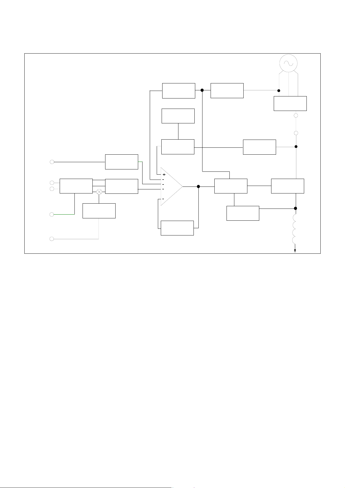
DESIGN DETAILS
PMG
ACCESSORY
INPUT
GENERATOR
VOLTAGE
SENSING
REMOTE
VOLTAGE
TRIMMER
CURRENT
INPUT
SENSING
RESISTORS
DROOP
OFFSET
CONTROL
ISOLATION +
AVERAGE
CONVERTER
UFRO
ENGINE
RELIEF
SOFT
START
CIRCUIT
PRECISION
VOLTAGE
REFERENCE
AMPLIFIER
STABILITY
CIRCUIT
SYNC
CIRCUIT
POWER
CONTROL
DRIVER
OVERLOAD
DETECTOR
+ INHIBIT
POWER
SUPPLIES
POWER
RECTIFIER
POWER
CONTROL
DEVICES
EXCITATION
CIRCUIT
BREAKER
(OPTIONAL)
EXCITER
STATOR
The main functions of the AVR are:
Sensing Resistors take a proportion of the generator output
voltage and attenuate it. This input chain of resistors includes the
range potentiometer and hand trimmer which adjust the generator
voltage. An isolating transformer is included to allow connection
to windings of different polarity and phase. An operational
precision rectifier converts the ac sensing voltage into dc for
further processing.
Quadrature droop circuit converts the current input into a
voltage which is phase mixed with the sensing voltage. The result
is a net increase in the output from the sensing network as the
power factor lags, causing the reduction in excitation needed for
reactive load sharing of paralleled generators.
A trimmer allows control over the amount of droop signal.
Offset Control provides an interface between the AVR and
accessories.
Power Supply components consist of zener diodes, dropper
resistors and smoothing to provide the required voltages for the
integrated circuits.
Precision voltage reference is a highly stable temperature
compensated zener diode for dc comparison.
Soft Start circuit overrides the precision voltage reference
during run-up to provide a linear rising voltage.
Main Comparator/Amplifier compares the sensing voltage to
the reference voltage and amplifies the difference (error) to
provide a controlling signal for the power device.
Stability circuit provides adjustable negative ac feedback to
ensure good steady state and transient performance of the
control system.
Power Control Driver controls the conduction period of the
output device. This is achieved by pedestal and ramp control
followed by a level detector and driver stage.
Power Control devices and rectifier vary the amount of exciter
field current in response to the error signals produced by the main
comparator.
Synchronising circuit provides a short pulse near the zero point
of one of the phases on the PMG and is used to synchronise the
Under Frequency Roll Off (UFRO) and power control circuits to
the generator cycle period.
UFRO circuit measures the period of each electrical cycle and
reduces the reference voltage linearly with speed below a
presettable threshold. A light emitting diode (LED) gives
indication of underspeed.
Engine Relief (load acceptance) circuit causes greater voltage
roll off (makes the volts/Hz slope steeper) to aid engine speed
recovery after application of a "block" load.
Overload detector continuously monitors the level of excitation
and provides signals to shut down the output device if overloads
last more than ten seconds. An overload condition produces a
latched fault requiring the generator to be stopped for reset.
 Loading...