

Stamford BC, BC164A, BC164B, BC164C, BC164D Installation, Service & Maintenance Manual
...
Installation, Service & Maintenance Manual for
STAMFORD BC
Range of Generators

SAFETY PRECAUTIONS
First Steps to Safe Operation
Read this manual, obey all Warnings and Cautions, and become familiar with the product.
Warnings & Notices used in this manual
The various warnings are out lined below and appear in the text in this format. Warnings and Cautions
appear at the appropriate position in the, to which they refer.
Warning: Information that draws attention to the risk of injury or death.
Caution: Information that draws attention to the risk of damage to the product, process or
surroundings.
Note: Used to convey, or draw attention to, additional information or explanations.
Notes appear after the text to which they refer.
Skill requirements of personnel
Service and maintenance procedures should only be carried out by experienced and qualified engineers,
who are familiar with the procedures and the equipment. Before any intrusive procedures are carried out,
ensure that the engine is inhibited and the generator is electrically isolated.
Electrical Equipment
All electrical equipment can be dangerous if not operated correctly. Always service and maintain the
generator in accordance with this manual. Always use genuine ‘STAMFORD’ replacement parts.
Warning: Electrical shock can cause injury or death. Ensure that all personnel operating,
servicing, maintaining or working near this equipment are fully aware of
the emergency procedures in case of accidents.
Before removing the protective covers to carry out service maintenance or repair, ensure that the engine
is inhibited and the generator is electrically isolated. The AVR access covers are designed to be removed
while the generator is on load.
Lifting
Lift the generator using the points provided with the aid of a spreader and chains. The angle on the
chains must be vertical during the lift. Do not lift single bearing generators without the, securely fitted,
transit bar. When removing the transit bar just prior to offering the generator up to the engine, be aware
that the rotor is not securely held in the generator. Keep the generator in the horizontal plane to when the
transit bar is not fitted.
Warning: The lifting points provided are designed for lifting the generator only. Do not lift
the Generating Set by the generator’s lifting points.
Note: Due to our policy of continuous improvement, details in this manual which were correct at time of
going to print and may now be due for amendment. Information included must therefore not be regarded
as binding.
Copyright 2010
2
TD_BC MAN GB_10.06_03_GB

Foreword
The Manual
Before operating, the generating set read this manual and all additional documentation supplied with it.
Great care has been taken with the design of this product to ensure that it is safe to operate. Misuse and
the failure to follow the safety precautions contained in the manual are potential causes of accidents.
Read the manual and make sure that all personnel who work on the equipment have access to the
manual. The manual should be considered as part of the product and should remain with the product.
Make sure that the manual is available to all users throughout the life of the product.
Scope
This manual contains guidance and instructions for the Installation, Servicing and Maintenance of the
generator.
It is not possible, within the scope of the manual, to teach the basic electrical and mechanical skills
required to safely carry out the procedures enclosed. The manual is written for skilled electrical and
mechanical technicians and engineers, who have prior knowledge and experience of generating
equipment of this type.
We offer a range of training courses that cover all aspects of STAMFORD generators.
Generator Designation
B C 1 8 4 D 1 (example)
BC - Generator type
I -
Applications,
I = Industrial, M = Marine.
1 - Frame size
8 18 = centre height in cm.
4 - Number of poles, 2 or 4
C - Core Size
1 - Number of bearings, 1 or 2
The Product
The product is an AVR controlled, self excited synchronous ‘ac
generator’. Designed for incorporation into a generating-set. (A
generating-set is defined as ‘machinery’ in European directives).
Serial Number Location
Each generator has a unique serial number stamped into the upper
section of the drive end of the frame.
The serial number is also shown on the nameplate.
Two other labels are located inside the terminal box, both fixed inside
of the terminal box, one on the sheet metal work and the other on the
main frame of the generator. Neither of these two labels is
considered to be permanently fixed.
Rating Plate
The generator has been supplied with a self-adhesive rating plate label to enable fitting after final
assembly and painting. Stick the nameplate to the outside of the non-drive end of the terminal box. The
surface in the area where a label is to be stuck must be flat, clean, and any paint finish must be fully dry
before attempting to attach label. Recommended method for attaching label is peel and fold back
sufficient of the backing paper to expose some 20 mm of label adhesive along the edge which is to be
located against the sheet metal protrusions. Once this first section of label has been carefully located and
stuck into position progressively peel off the backing paper and smooth down with a clean cloth. The
adhesive will achieve a permanent bond in 24 hours.
A factory fitted metal nameplate is available for some applications.
Caution. Do not exceed the parameters marked on the rating plate.
TD_BC MAN GB_10.06_03_GB
3
Copyright 2010

Contents
SAFETY PRECAUTIONS ............................................................................................................................ 2
F
IRST STEPS TO SAFE OPERATION
W
ARNINGS & NOTICES USED IN THIS MANUAL
S
KILL REQUIREMENTS OF PERSONNEL
E
LECTRICAL EQUIPMENT
L
IFTING
.................................................................................................................................................... 2
FOREWORD ................................................................................................................................................ 3
T
HE MANUAL
S
COPE
G
ENERATOR DESIGNATION
T
HE PRODUCT
S
ERIAL NUMBER LOCATION
R
ATING PLATE
CONTENTS .................................................................................................................................................. 4
INTRODUCTION .......................................................................................................................................... 6
G
ENERAL DESCRIPTION
S
ELF-EXCITED
M
AIN STATOR POWERED AVR
F
OR PARALLEL OPERATION
A
UXILIARY WINDING
T
RANSFORMER CONTROLLED GENERATORS
S
TANDARDS
E
UROPEAN DIRECTIVES
APPLICATION OF THE GENERATOR ....................................................................................................... 9
E
NVIRONMENTAL PROTECTION
A
IRBORNE CONTAMINATES
H
IGH HUMIDITY ENVIRONMENTS
V
IBRATION
B
EARINGS
INSTALLATION INTO THE GENERATING SET ...................................................................................... 12
D
ELIVERY
H
ANDLING THE GENERATOR
S
TORAGE
A
FTER STORAGE
R
OTOR BALANCING
G
ENERATOR VIBRATION, FREQUENCY
S
IDE LOADS
C
OUPLING ARRANGEMENTS
BCA, S
E
ARTH ARRANGEMENT
P
AINT FINISH
W
ARNING LABELS
PRE-R
D
IRECTION OF ROTATION
P
HASE ROTATION
V
OLTAGE AND FREQUENCY
AVR
ADJUSTMENT
A
CCESSORIES
AUTOMATIC VOLTAGE REGULATORS ................................................................................................. 19
INITIAL START-UP .....................................................................................E
A
CCESSORIES
INSTALLATION ON SITE .......................................................................................................................... 25
............................................................................................................................................ 3
..................................................................................................................................................... 3
.......................................................................................................................................... 3
.......................................................................................................................................... 3
AVRC
. ............................................................................................................................................ 6
.............................................................................................................................................. 10
.............................................................................................................................................. 10
............................................................................................................................................... 12
............................................................................................................................................... 12
............................................................................................................................................ 13
INGLE BEARING COUPLING ALIGNMENT
.......................................................................................................................................... 17
UNNING CHECKS
........................................................................................................................................ 18
............................................................................................................................................... 22
........................................................................................................................... 2
........................................................................................................................ 3
............................................................................................................................ 6
ONTROLLED GENERATORS
.................................................................................................................................. 6
. ........................................................................................................................... 7
........................................................................................................................ 9
.................................................................................................................................... 12
................................................................................................................................. 12
............................................................................................................................ 17
................................................................................................................................... 17
........................................................................................................................... 17
........................................................................................................................ 17
................................................................................................................................... 17
.................................................................................................................................. 18
............................................................................................................ 2
............................................................................................. 2
........................................................................................................ 2
....................................................................................................................... 3
........................................................................................ 6
................................................................................................................... 6
....................................................................................................................... 6
.............................................................................................. 6
.................................................................................................................. 9
................................................................................................................. 9
..................................................................................................................... 12
...................................................................................................... 12
..................................................................................................................... 13
........................................................................................ 14
..................................................................................................................... 18
RROR! BOOKMARK NOT DEFINED
.
Copyright 2010
4
TD_BC MAN GB_10.06_03_GB

SERVICE AND MAINTENANCE ............................................................................................................... 27
S
ERVICE
W
P
ROCEDURE FOR INSULATION TESTING
M
T
YPICAL DRYING OUT CURVE
A
IR FILTERS
M
R
EMOVAL AND REPLACEMENT OF COMPONENT ASSEMBLIES
................................................................................................ E
INDING CONDITION
.............................................................................................................................. 27
................................................................................................... 28
ETHODS OF DRYING OUT GENERATORS
................................................................................................ 28
.................................................................................................................. 29
........................................................................................................................................... 30
AINTENANCE
........................................................................................................................................ 31
RROR! BOOKMARK NOT DEFINED
................................................................... 37
SPARES AND AFTER SALES SERVICE ................................................................................................. 41
.
TD_BC MAN GB_10.06_03_GB
5
Copyright 2010
INTRODUCTION
General Description
The BC16/18 range of generators is of brushless rotating field design, available up to 660V/50Hz (1500
rpm, 4 pole and 3000 rpm, 2 pole) or 60Hz (1800 rpm, 4 pole and 3600 rpm, 2 pole), and built to meet
B.S. 5000 Part 3 and international standards.
The BC16/18 range are self-excited with excitation power derived from the main output windings, using
either the AS440 AVR or transformer controlled excitation system.
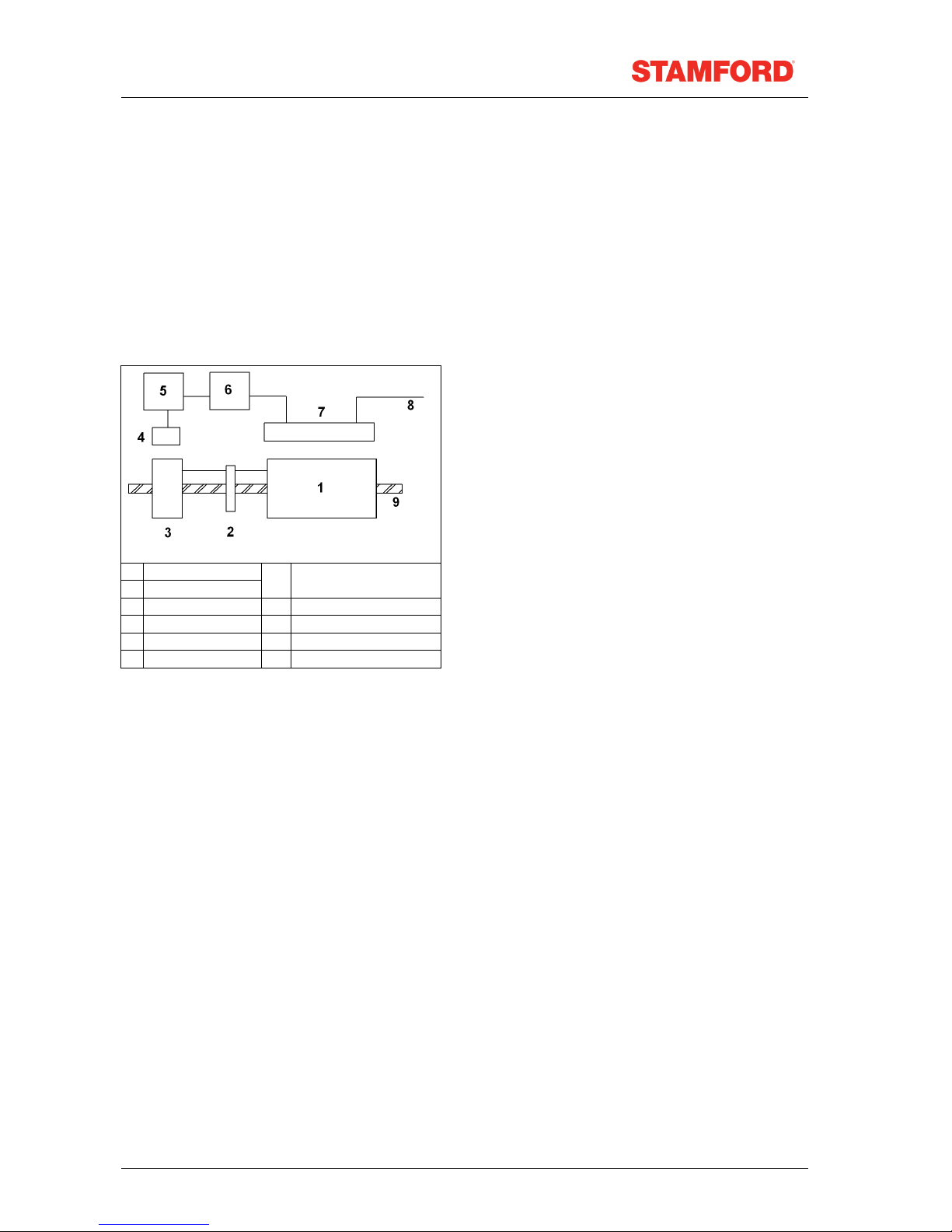
Self-Excited AVR Controlled Generators
Main Stator Powered AVR
The main stator provides power for excitation of the
exciter field via the SX460 AVR which is the
controlling device governing the level of excitation
provided to the exciter field. The AVR responds to a
voltage-sensing signal derived from the main stator
winding. By controlling the low power of the exciter
field, control of the high power requirement of the
main field is achieved through the rectified output of
1 Main rotor
2 Rotating diodes
6 Isolating transformer
(if fitted)
3 Exciter rotor 7 Main stator
4 Exciter stator 8 Output
5 AVR 9 Shaft
the exciter armature. The AVR senses average
voltage on two phases ensuring close regulation. In
addition it detects engine speed and provides voltage
fall off with speed, below a pre-selected speed (Hz)
setting, preventing over-excitation at low engine
speeds and softening the effect of load switching to
relieve the burden on the engine. The detailed
function of the AVR circuits and their adjustment are
covered in the load testing section.
For Parallel operation
The AS440 AVR also incorporates circuits which, when used in conjunction with accessories, can provide
for parallel operation with 'droop' control.
Function and adjustment of the accessories, which can be fitted.
Inside the generator terminal box are covered in the accessories section of this book. Separate
instructions are provided with other accessories available for control panel mounting.
Auxiliary Winding
An auxiliary winding can also provide the power for excitation of the exciter field via the AS440 AVR to
provide short circuit maintenance when required.
Transformer Controlled Generators
The main stator provides power for excitation of the exciter field via a transformer rectifier unit. The
transformer combines voltage and current elements derived from the main stator output to form the basis
of an open-loop control system, which is self regulating in nature. The system inherently compensates for
load current magnitude and power factor and provides short circuit maintenance in addition to a good
motor starting performance. Three-phase generators normally have a three-phase transformer control for
improved performance with unbalanced loads but a single-phase transformer option is available. No
accessories can be provided with this control system.
Standards.
STAMFORD ac generators meet the relevant parts of national and international standards pertaining to
generators. The generator must be operated within the limits laid down in the relevant standards and
within the parameters on the generator rating plate.
Copyright 2010
6
TD_BC MAN GB_10.06_03_GB

Set. To reflect this each generator is
Marine generators meet the requirements of all the major marine classification societies.
European Directives.
AC generators sold for use in the European
Union must meet the relevant European
directives. An ac generator has no intrinsic
function; it must be have a mechanic input in
order to provide an electrical output. The
generator is supplied as a component part of a
Generatingsupplied with an ‘EC Declaration of
Incorporation’ in accordance the Machinery
Directive.
The ac generator meets the relevant directives
applicable to an ac generator (component part)
before it is incorporated into ‘machinery’.
The directives identified as pertaining to ac generators are:
The Machinery (Safety) Directive, 98/37/EEC.
The Low Voltage Directive, 73/23/EEC.
The EMC Directive, 89/336/EEC
The generator is CE marked; CE labels are supplied loose in case the generating set manufacturer needs
to paint the generating set before delivery to the end user.
Note: Once the generator is build into a generating-set (machinery), it is the responsibility
of the generating-set manufacture to ensure that the generating-set
complies with the relevant EC Directives.
It is contrary to the EC Directives to misrepresent compliance of the EC directives by displaying the CE
mark supplied with a component part of the product. The directive requires compliance to be assessed as
a component part, as the complete product and during installation on site.
Applications for use within the EU
STAMFORD ac generators are supplied on the basis that:
They are used for power generation or related functions.
They are to be applied in one of the following environments:
Portable (open construction – temporary site supply)
Portable (enclosed – temporary site supply)
Containerised (temporary or permanent site supply)
Ship – borne, below decks (marine auxiliary power)
Commercial vehicle (road transport / refrigeration etc.)
Road transport (auxiliary power)
Industrial vehicle (earthmoving, cranes etc.)
Fixed installation (Industrial – factory / process plant)
Fixed installation (residential, commercial and light industrial – home / office / health.)
Energy management (combined heat & power and/or peak lopping.)
Alternative energy schemes.
The standard generators are designed to meet the ‘industrial’ emissions and immunity standards. Where
the generator is required to meet the residential, commercial and light industrial emissions and
immunity standards reference must be made to document reference N4/X/011. This publication
outlines the additional equipment that may be required.
The installation ‘earth/ground’ arrangements require the connection of the generator frame to the site
protective earth conductor using a minimum lead length.
Maintenance and servicing with unauthorised parts, not of STAMFORD brand, will invalidate us from any
liability for EMC compliance.
Installation, maintenance and servicing are carried out by adequately trained personnel fully aware of the
requirements of the relevant EC directives.
TD_BC MAN GB_10.06_03_GB
7
Copyright 2010

Unsuitable Applications
Synchronous generators require a constant speed for power generation. Applications where the
generator is not run at a constant speed are not suitable for the standard generator. Such applications
may be possible within certain parameters. Contact the factory for advice, there is every possibility that
we can provide you with a satisfactory technical solution to meet your requirement.
Additional information for EMC compliance
Standard generators are designed to meet the ‘industrial’ emissions and immunity standards. Where the
generator is required to meet the residential, commercial and light industrial emissions and immunity
standards, reference must be made to document reference N4/X/011. This publication outlines the
additional equipment that may be required.
Copyright 2010
8
TD_BC MAN GB_10.06_03_GB

Application of the generator
Environmental Protection
STAMFORD generators are protected to IP23. IP23 is not adequate protection for use outdoors without
additional measures.
Ambient Temperature <40oC
Humidity <60%
Altitude <1000m
Air Flow
The airflow requirements for the generator can be found in the Data section at the back of this manual.
Ensure that the air inlets and outlets are not obstructed when the generator is running.
Airborne Contaminates
Contaminates such as salt, oil, exhaust fumes, chemicals, dust, sand, etc., will reduce the effectiveness
of the insulation and lead to premature failure of the windings. Consider using air filters or an enclosure to
protect the generator.
This table represents the normal operating conditions that the
generator is designed for. Operation outside of these parameters is
possible after due consideration and will be reflected on the
generator nameplate. If the operating environment for the generator
has changed after purchase, the rating of the generator needs to be
revised, refer to the factory for details.
Air Filters
Air filters are available on request. Filters present a restriction to the airflow so the rating of the generator
must be reduced by 5%. If the filters are supplied, factory fitted, the rating on the nameplate will include
the reduced rating. The filters can be up-fitted after delivery in which case the customer must apply the
power reduction.
Air filters remove airborne particulates above 3 microns. The frequency of changing and cleaning the
filters depend on the site conditions. We recommend that the filters are monitored frequently until a
suitable cycle of change is established.
Air filters do not remove water. Additional protection must be employed to prevent the filters from getting
wet. If the filters are allowed to get wet the airflow will be restricted and the generator will overheat. This
will reduce the life expectancy of the insulation leading to premature failure of the generator.
High Humidity environments
The humidity of the air will allow condensation to form on the windings if the temperature of the windings
falls below the dew point. The dew point is a relationship between the ambient temperature and humidity.
In areas of high humidity additional protection may be required even if the generator is fitted inside an
enclosure.
Anti-condensation heaters
Anti-condensation heaters are designed to raise the temperature of the windings above the temperature
of the surrounding material so that the condensation will not form on the windings.
We recommend that anti-condensation heaters are fitted to all generators that are left switched off for any
period of time. The best practice is to wire the heaters such that the heaters come on when the generator
is switched off. This is particularly important in applications where high humidity is a significant problem.
Always check the condition of the generators windings before switching the generator on. If moisture is
observed carry out one or more of the drying-out methods outlined in the Service section of this manual.
Enclosures
An enclosure should be employed to protect the generator from adverse environmental conditions.
If the generator is to be fitted inside an enclosure, ensure that there is adequate airflow to support both
the engine and the generator. Ensure that the generator air supply is clean (free from moisture and
contaminates) and at or below the ambient temperature stated on the rating plate.
TD_BC MAN GB_10.06_03_GB
9
Copyright 2010

Vibration
STAMFORD generators are designed to withstand the vibration levels encountered on generating sets
built to meet the requirements of ISO 8528-9 and BS 5000-3. (Where ISO 8528 is taken to be broad band
measurements and BS5000 refers to the predominant frequency of any vibrations on the generating set).
Definition of BS5000 – 3
Generators shall be capable of continuously withstanding linear vibration levels with amplitudes of
0.25mm between 5Hz and 8Hz and velocities of 9.0mm/s rms between 8 Hz and 200 Hz, when measured
at any point directly on the carcass or mainframe of the machine. These limits refer only to the
predominant frequency of vibration of any complex waveform.
Definition of ISO 8528 - 9
ISO 8528-9 refers to a broad band of frequencies; the broad band is taken to be between 2 Hertz and 300
Hertz. The table below is an example from ISO 8528 - 9 (value 1). This simplified table lists the vibration
limits by kVA and speed for acceptable genset operation.
Vibration Levels As Measured On The Generator
Engine Speed Min -
The ‘Broad band’ is taken as 2 Hz - 300 Hz
Caution: Exceeding either of the above specifications will have a detrimental effect on the
1
Set Output Kva Vibration
Displacement
(S rms)
Vibration
Velocity
(V rms)
Vibration
Acceleration
(a rms)
<,50 kVA 0.64 mm 40 mm/sec 25 m/sec2 1500 – 1800 (rpm)
> 50 but < 125 0.4 mm 25 mm/sec 16 m/sec2
life of the bearings and other components. This will invalidate the
generator warranty.
Vibration Monitoring
We recommend that the set builder checks the vibration levels using vibration analysing equipment.
Ensure that the vibration levels of the generating set are within the levels stated in BS 5000-3 and ISO
8528-9. If the vibration levels are not within tolerance the genset builder should investigate the root cause
of the vibrations and eliminate them. The ‘best practice’ is for the genset builder to take initial readings as
a base line and the user to periodically monitor the genset and bearings to detect any deteriorating trend.
It will then be possible to plan ahead for bearing changes and eliminate vibration problems before
excessive damage to the generating set occurs.
Vibration checks should be made every 3 months.
Excessive Vibration levels
If the vibration levels of the generating set are not within the parameters quoted above:
Consult the genset builder; the genset builder should address the genset design to reduce the vibration
levels as much as possible.
Discuss, with us, the impact of not meeting the above levels on both bearing and generator life
expectancy.
When requested, or it is deemed necessary, we will work with the genset builder in an attempt to find a
satisfactory solution.
Bearings
Sealed for life or re-greasable bearings are fitted to the P range of generators. The bearings are fitted
within machined housings, these housings form an assembly located and bolted, within the end brackets.
All of the have bearings have pressed steel cages and are type C3. The grease used is a high
specification synthetic compound that must not be mixed with grease with a different specification.
Re-greasable Bearings
When re-greasable bearings are fitted the bearing housings incorporate fittings for pipe work to an
external grease nipple. Generators with re-greasable bearings are supplied with information labels
advising the user of grease type, re-lubrication frequency, and the quality of grease to be used. These
Copyright 2010
10
TD_BC MAN GB_10.06_03_GB

instructions must be followed. The information is repeated in the Data section of this manual. The bearing
housing has a grease escapement slot at the bottom of the outer area. At the drive end the grease,
expelled from the escapement slot, will discharge into the coupling area. At the non-drive end the grease,
from escapement slot, is deflected by a metal plate to ensure that it cannot foul the Permanent Magnet
Generator (PMG). The sheet metal cover over the PMG has a slot at the bottom to enable the excess
grease to escape.
Bearing Life
Factors that effect bearing life:
The life of a bearing in service is subject to the working conditions and the environment:
High levels of vibration from the engine or misalignment of the set will stress the bearing and reduce its
service life. If the vibration limits set out in BS 5000-3 and ISO 8528-9 are exceeded bearing life will
be reduced. Refer to ‘Vibration’ below.
Long stationary periods in an environment where the generator is subject to vibration can cause false
brinnelling, which puts flats on the balls and grooves on the races, leading to premature failure.
Very humid atmospheric or wet conditions can emulsify the grease causing corrosion and deterioration of
the grease, leading to premature failure of the bearings.
Health Monitoring of the Bearings
We recommend that the user check the bearing condition, using monitoring equipment, to determine the
state of the bearings. The ‘best practice’ is to take initial readings as a base line and periodically monitor
the bearings to detect a deteriorating trend. It will then be possible to plan a bearing change at an
appropriate generating set or engine service interval.
Bearing 'Service Life' Expectancy
Bearing manufacturers recognise that the “service life” of their bearings is dependent upon many factors
that are not in their control; they cannot therefore quote a “service life”.
Although “service life” cannot be guaranteed, it can be maximised by attention to the generating set
design. An understanding of the generating set’s application will also help the user to maximise the
service life expectancy of the bearings. Particular attention should be paid to the alignment, reduction of
vibration levels, environmental protection, maintenance and monitoring procedures.
We do not quote life expectancy figures for bearings, but suggests practicable replacement intervals
based on the L10 life of the bearing, the type of grease and the recommendations of the bearing and
grease manufacturers.
For general-purpose applications: providing the correct maintenance is carried out, vibration levels do not
exceed the levels stated in ISO 8528-9 and BS5000-3, and the ambient temperature does not exceed
50°C. Plan to replace bearings within 30,000 hours of operation.
It is important to note that bearings in service, under good operating conditions, can continue to run
beyond the recommended replacement period. It should also be remembered that the risk of bearing
failure increases with time.
If in doubt about any aspect of the ‘bearing life’ on STAMFORD generators, contact your nearest supplier
of STAMFORD generators or contact the Stamford factory direct.
TD_BC MAN GB_10.06_03_GB
11
Copyright 2010
Installation into the Generating Set
The generator is supplied as a component part for installation into a ‘generating set’.
Delivery
Upon receipt of the generator, check the generator for damage that may have occurred during transport.
Also check that the rating-plate details are correct and as ordered for the application.
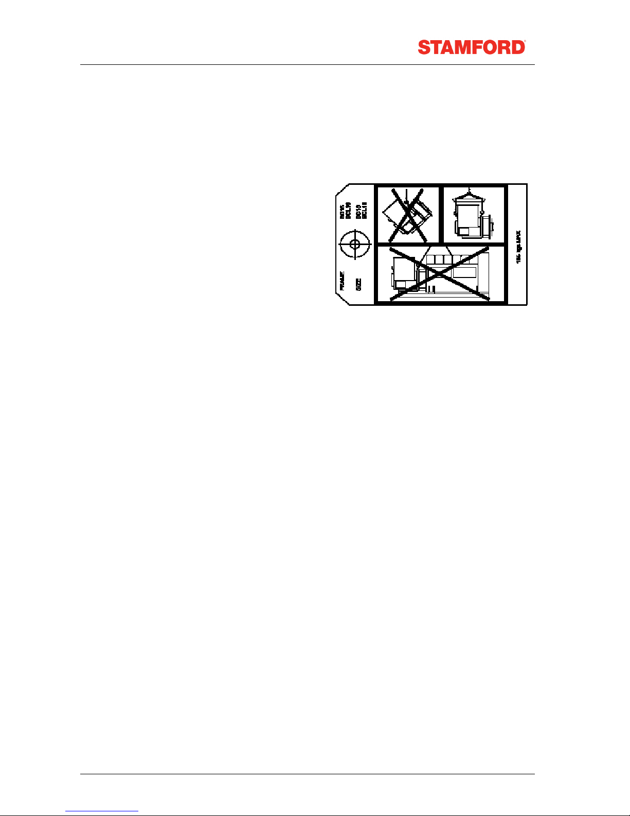
Handling the generator
When lifting the generator use a spreader bar to ensure
that the angle on the lifting chains are vertical to the
lifting position on the generator.
Warning: The generator lifting points are
designed to lift the generator
only. Do not lift the complete
generating set by the generator
lifting points.
Single bearing generators have a transit bar fitted at the drive end. This bar holds the rotor in position
during transit. The transit bar should be left in position until it is necessary to remove it to allow the
generator to be coupled to the engine.
Warning: If the generator is moved without the transit bar be aware that the rotor
could fall out of the frame. When moving the generator always keep it in
the horizontal plane, this will reduce the risk of the rotor falling out.
Storage
If the generator is not to be used immediately, it must be stored in a clean, dry, vibration free
environment. If anti-condensation heaters are fitted, switch them on. If heaters are not fitted use other
means to ensure that condensation cannot form on the windings.
Spin the shaft by hand every month to prevent flat spots in the bearings and to free up the grease.
After Storage
After a period of storage, carry out ‘pre running checks’ to determine the condition of the windings. If the
winding are damp or the insulation is low, follow one of the ‘drying out procedures’, in the Service section
of this manual. Replace the bearing after 12 months in storage. (See the Maintenance section)
Rotor balancing
Dynamic balancing of the generator rotor assembly has been carried out during manufacture in
accordance with BS 6861 Part 1 Grade 2.5 to ensure vibration limits of the generator are in accordance
with BS 4999 Part 142.
Generator Vibration, Frequency
The main vibration frequencies produced by the component generator are as follows:
4-pole 1500 r.p.m. 25 Hz
4-pole 1800 r.p.m. 30 Hz
2-pole 3000 r.p.m. 50 Hz
2-pole 3600 r.p.m. 60 Hz
However, vibrations induced by the engine are complex and contain frequencies of 1.5, 3, 5 or more
times the fundamental frequency of vibration. These induced vibrations can result in generator vibration
levels higher than those derived from the generator itself. It is the responsibility of the generating set
Copyright 2010
12
TD_BC MAN GB_10.06_03_GB

designer to ensure that the alignment and stiffness of the bedplate and mountings are such that the
vibration limits of BS5000 part 3 and ISO 8528 part 9 are not exceeded.
In standby applications where the running time is limited and reduced life expectancy is accepted, higher
levels than specified in BS5000 part 3 can be tolerated, up to a maximum of 18mm/sec.
Side Loads
In the case of belt driven generators, ensure alignment of drive end and driven pulleys to avoid axial load
on the bearings. Screw type tensioning devices are recommended to allow accurate adjustment of belt
tension whilst maintaining pulley alignment.
Belt and pulley guards must be provided by the set builder.
Important ! Incorrect belt tensioning will result in excessive bearing wear.
2/4-Pole
Side Load
kgf N
Shaft extension mm
BC16 92 900 82
BC18 173 1700 82
Coupling Arrangements
Single and two bearing arrangements are available both arrangements can be close coupled. Both
arrangements also need a firm level foundation.
Two bearing generators require a substantial bedplate with engine/generator mounting pads to ensure a
good base for accurate alignment. Close coupling of the engine to the generator can increase the overall
rigidity of the set. A flexible coupling, designed to suit the specific engine/generator combination, is
recommended to minimise the torsional effects.
Accurate alignment of single bearing generators is essential, vibration can occur due to the flexing of the flanges
between the engine and generator. A substantial bedplate with engine/generator mounting pads is required.
For the purposes of establishing set design the bending moment at the engine flywheel housing to
generator adaptor interface should not exceed 125ft.lb. (17 kgm).
The maximum bending moment of the engine flange must be checked with the engine manufacturer.
Torsional vibrations occur in all engine-driven shaft systems and may be of a magnitude to cause
damage at certain critical speeds. It is therefore necessary to consider the torsional vibration effect on the
generator shaft and couplings.
It is the responsibility of the generator set manufacturer to ensure compatibility, and for this purpose
drawings showing the shaft dimensions and rotor inertias are available for customers to forward to the
engine supplier. In the case of single bearing generators coupling details are included.
Caution: Torsional incompatibility and/or excessive vibration levels can cause
damage or failure of the generator and/or engine components.
Coupling Two Bearing Generators
A flexible coupling should be fitted and aligned in accordance with the coupling manufacturer's
instruction.
If a close coupling adaptor is used the alignment of machined faces must be checked by offering the
generator up to the engine. Shim the generator feet if necessary. Ensure adaptor guards are fitted after
generator/engine assembly is complete. Open coupled sets require a suitable guard, to be provided by
the set builder.
Axial loading of the generator bearings should be avoided. Should it be unavoidable contact the factory
for advice.
Warning: Incorrect guarding and/or generator alignment can result in injury and/or
equipment damage.
TD_BC MAN GB_10.06_03_GB
13
Copyright 2010

Coupling Single Bearing Generators
Alignment of single bearing generators is critical. If necessary, shim the generator feet to ensure
alignment of the machined surfaces.
For transit and storage purposes the generator frame spigot and rotor coupling plates have been coated
with a rust preventative. This MUST BE removed before assembly to engine.
A practical method for removal of this coating is to clean the mating surface areas with a de-greasing
agent based on a petroleum solvent.
Warning: Care should be taken not to allow any cleaning agent to come into
prolonged contact with skin.
BCI, 4-pole Single Bearing Coupling Alignment
1) On the engine check the distance from the coupling mating face on the flywheel to the flywheel
housing mating face. This should be within 0.5mm of nominal dimension. This is necessary to
ensure that a thrust is not applied to the ac generator bearing or engine bearing.
2) Check that the bolts securing the flexible plates to the coupling hub are tight and locked into
position. Refer to the Data section of the manual for tightening torques. (75Nm : 55 lb/ft)
3) Remove air outlet covers from the drive end of the generator to gain access to coupling and
adaptor bolts. Check that coupling joint interfaces are clean and lubricant free.
4) Check that coupling discs are concentric with adaptor spigot. This can be adjusted by the use of
tapered wooden wedges between the fan and adaptor. Alternatively, the rotor can be suspended
by means of a rope sling through the adaptor opening.
5) Consider using alignment studs to ensure that the disc and the flywheel are in alignment.
6) Offer the generator to engine and engage both coupling discs and housing spigots at the same
time, pushing generator towards engine until coupling discs are against flywheel face, and the
housing spigots are located.
Caution: Do not pull the generator to the engine using bolts through the flexible
discs.
7) Fit housing and coupling bolts, taking care to use heavy gauge washers between coupling bolt
head and coupling disc. Tighten bolts evenly around assembly sufficiently to ensure correct
alignment.
8) Tighten housing bolts.
9) Tighten coupling disc to flywheel bolts. Refer to engine manufacturer’s manual for correct
tightening torque.
10) Remove rotor aligning aids, the sling, or wooden wedges and replace all covers.
Caution: Incorrect generator alignment can result in damage to the generator.
Warning: Failure to replace protective covers can result in injury.
BCA, Single Bearing Coupling Alignment
Generators offered in the BCA range can be specified to suit different engine build configurations of
specific flywheel and flywheel housing combinations.
Important: It is most important that the appropriate generator build is ordered with
prior knowledge of the intended engine flywheel/housing arrangement.
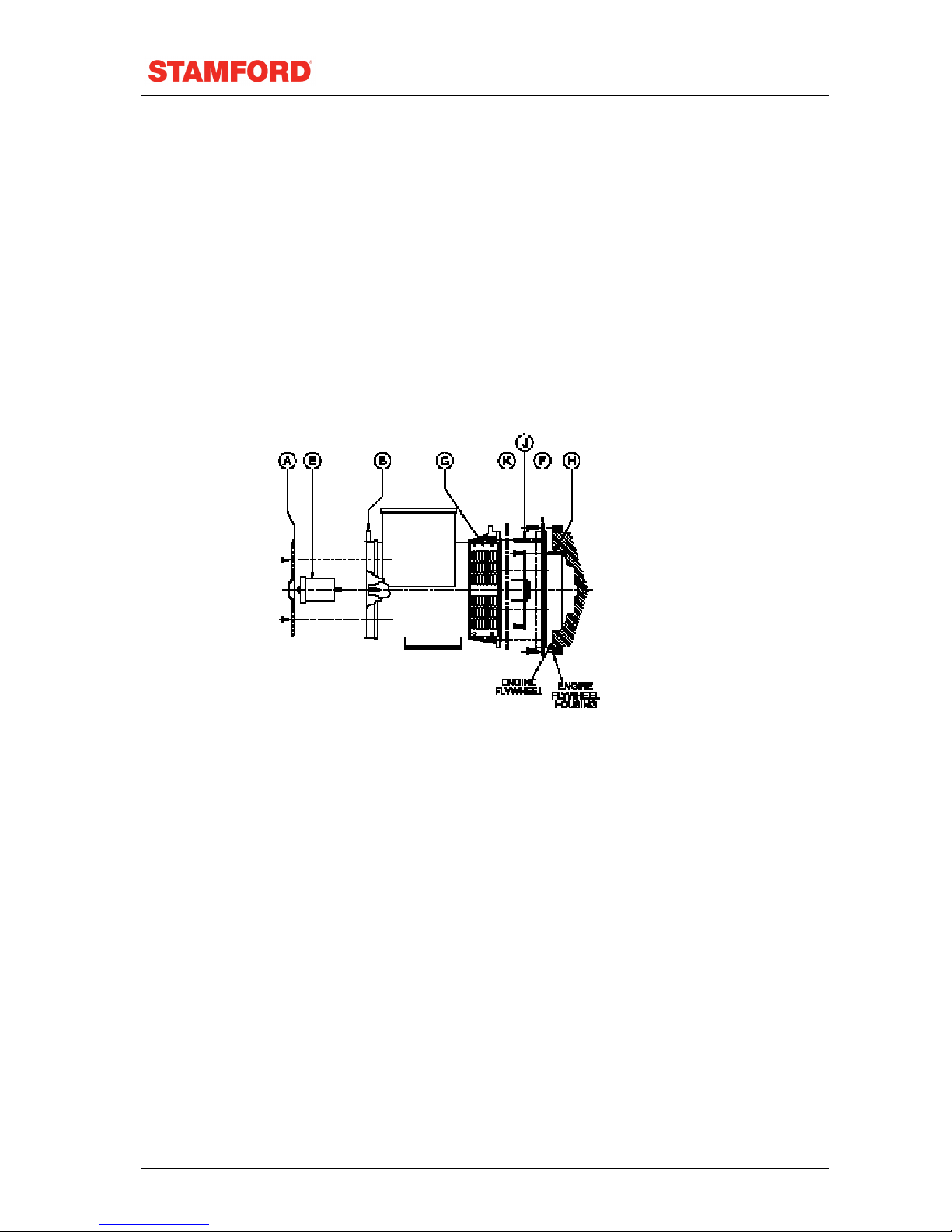
11) Remove louvered cover "A" from non-drive endbracket "B".
12) Assemble locating bar "E" ( No AF1609) by screwing into shaft.
13) Remove transit bar "K".
14) Remove side screens "G".
15) If the adaptor ring is an individual item, as indicated "F", bolted to the generator D.E. bracket,
remove from generator and fit to engine flywheel housing.
16) Thread two locating pins "H" into two top flywheel holes.
17) Fit two locating pins "J" into two top holes of the engine flywheel housing/adaptor location holes.
18) Pick up generator by the cast lifting lugs on both ends with 1/2 ton shackles (TO BS3032) or
lifting hooks using suitable lifting equipment.
Copyright 2010
14
TD_BC MAN GB_10.06_03_GB
19) Rotate generator rotor such that two top holes of coupling disc are in close axial alignment.
20) Push the generator rotor forward only half (50mm) the available movement provided by locating
bar "E". It may be necessary to tap bar "E" with a hide mallet to ease the bearing out of housing.
Important! Do not push the rotor forward too far. There is a risk that the rotor will rest
on the stator winding outhang resulting in winding damage especially if
any rotational movement occurs during alignment with pins "H".
21) Support the weight of the rotor at the coupling end whilst sliding the rotor forward to locate
coupling disc holes oversupport pins "H". Locating bar "E" will allow the rotor to move forward a
further 50mm, the total movement bar "E" allows being 100mm. With coupling discs positioned
against flywheel location fit securing screws and washers. Remove pins "H" and fit two final
securing screws and washers.
22) Push generator onto engine guiding adaptor over locating pins "J" and onto engine flywheel
housing location, or ring "F", secure with screws and washers. Remove pins and replace with two
screws and washers.
23) Remove locating bar "E". Replace M10 screw "C" for barring purposes.
24) Remove lifting tackle and replace side screens "G" and louvered cover "A".
ENGINE FLYWHEEL
ENGINE FLYWHEEL HOUSING
BCA, Single Bearing 2-Pole Generator To Engine Assembly Instructions (With Doweled
Flywheels)
Follow steps 1 – 5 from BCA, 4-pole instruction procedure.
Fit the two location dowels pins into appropriate diametrically opposite holes in engine flywheel, leaving
sufficient parallel diameter exposed to allow for positive location of the disc-spacer-ring and coupling
discs.
Fit the disc-spacer-ring over the two dowel pins and position firmly against the flywheel face.
Follow steps 6 – 8 from BCA 4-pole instruction procedure.
Rotate generator rotor such that the two coupling disc dowel holes align with flywheel dowel pins, and two
top holes of coupling discs are in close axial alignment with the two flywheel location pins "H".
Follow step 10 and 11 from BCA 4-pole instruction procedure.
Support the weight of the rotor at the coupling end whilst sliding the rotor forward to locate coupling disc
holes over support pins "H".
TD_BC MAN GB_10.06_03_GB
15
Copyright 2010
Important! Ensure coupling disc dowel pinholes are in correct alignment. With the
coupling disc positioned against flywheel location fit securing screws and
washers. Remove pins "H" and fit two final securing screws and washers.
Follow steps 12 – 14 from 4-pole instruction procedure.
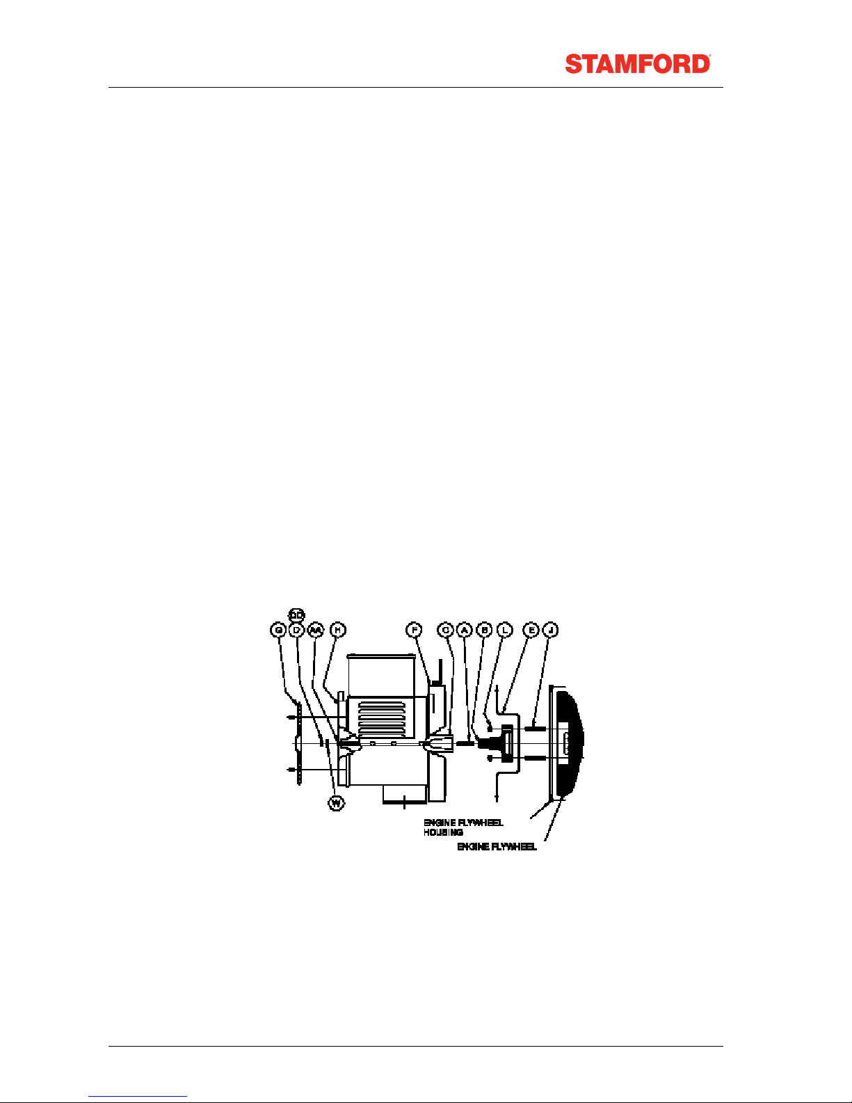
BCL Taper Shaft Arrangements
This arrangement is used on the BCL style generators.
As with single bearing generators alignment is critical. If necessary shim the generator feet to ensure
alignment of the machined surfaces.
The following procedure should be adopted to assemble the generator to the engine:
25) Remove louvred end cover "G" from non drive end bracket "H" and M10 Hex Nut "D" from shaft
securing stud "AA".“ Remove transit bar "E" and withdraw stub shaft/shaft securing stud "A/B"
from rotor.
26) Ensure alternator, engine flywheel and flywheel housing locating spigots, faces and recesses are
free from paint or preservatives.
27) Locate stub shaft/shaft securing stud assembly "A"/"B" on engine flywheel spigot and secure with
studs "J", M12 hex. nut "L" or bolts. Refer to engine manual for torque settings.
28) Ensure both tapers are clean and free of burrs, oil or grease. Slide alternator complete with rotor
towards engine, ensuring that shaft securing stud "A" enters central hole in rotor shaft. Refer to
engine manual for torque settings.
29) Secure alternator adaptor "F" to engine flywheel housing. Tap adaptor into place before
tightening. Refer to engine manufacturer for torque setting.
30) Fit M10 Binx nut "DD" to protruding shaft securing stud "AA". M10 Binx nut tightening torque
45.0Nm (33.0 lbs.ft).
31) Fit louvred endcover "G" to non drive endbracket "H".
32) Check for excessive vibration at time of initial run-up.
Caution Incorrect guarding and/or generator alignment can result in personal injury
and/or equipment damage
Copyright 2010
16
TD_BC MAN GB_10.06_03_GB
 Loading...