

Stallion SLC938 User Manual
Model: SLC938
Sunliner Coach - Corona, California U.S.A.

Sunliner Coach (a Stallion Bus Industries Company) is pleased to provide you, our
customer, with the highest quality product available on the market today. We strive to
ensure that all our vehicles meet or exceed all applicable Federal, State, and Local laws
and statutes for safety and operability for varied on-the-road usage requirements.
The vehicles manufactured by Sunliner Coach are constructed with ease of operation
and economical durability in mind, for the life of the coach and its operating systems.
We take great pride in producing a cost-effective product for your use and for the safety
and comfort of your passengers.
Every component of this transportation system is vital to the safety and durability of this
vehicle and at no time should any system or part be neglected, removed, or altered in
any manner that will compromise safety or operability of the vehicle or the safety and
well-being of passengers and the operator.
It is the responsibility of the owner of this coach to maintain all systems and
components in serviceable and working condition. Always maintain and operate this
coach with parts and information provided by Sunliner Coach for many years of troublefree driving, and a safe and comfortable travel experience.
PLEASE READ BEFORE OPERATING THIS VEHICLE
THIS OPERATOR MANUAL MUST REMAIN WITH THE VEHICLE THROUGHOUT ITS
SERVICE LIFE, AND MUST BE TRANSFERRED TO ANY FUTURE OWNERS OR
OPERATORS AS AN IMPORTANT PART OF THIS TRANSPORTATION SYSTEM.
Stallion Bus Industries (“the manufacturer”) will, at its discretion, add to or edit this
document as needed to provide the owner with any updates required by law or with
information affecting the operation or safety of this coach. Stallion Bus Industries
reserves all rights to this document in its entirety, and any copying, duplication, or
changes to this manual are strictly prohibited, unless specific permission is granted by
the manufacturer to the licensed operator or owner of this coach. Please submit any
questions regarding this document to:
Stallion Bus Industries
1592 Jenks Dr. Corona, CA 92880
(951) 737-7777
http://www.stallionbus.com
THANK YOU FOR CHOOSING STALLION BUS PRODUCTS FOR YOUR TRANSPORTATION NEEDS.

GENERAL INFORMATION
EXTERIOR COMPONENTS
INTERIOR COMPONENTS
CONTROLS
MECHANICAL
TRANSMISSION
ELECTRICAL
ACCESSORIES / OPTIONS

1- GENERAL INFORMATION
Sunliner Coach - Corona, California U.S.A.

GENERAL INFORMATION
VEHICLE IDENTIFICATION NUMBER (VIN)
The Vehicle Identification Number is stamped on a plate located inside the vehicle on the upper step
adjacent to the curbside wall.
The D.O.T. Certification Plate certifies that the vehicle complies with all Federal Motor Vehicle Safety
Standards for operation of a vehicle on public roadways in effect at the time of manufacture. This plate is
located on the first step on the aisle side of the driver’s seat.
Information such as manufacturer’s name and address, date of manufacture, gross vehicle weight, tire
type and pressures, and are also on this plate. Refer to the VIN whenever requesting service parts, recall
information.

GENERAL INFORMATION
The ultimate responsibility for the safe operation of a motor vehicle is the duty of the operator. In
the case of motor coach transport, many individual lives may be endangered if certain commonsense items are ignored or dismissed. Due to the nature of tort law and damages compensation
law, it is of the utmost importance that you, the operator, take it upon yourself to insure that your
vehicle and all of its systems are in operable condition and have been maintained to all pertinent
specifications of the manufacturer and state and federal regulations.
Before operating the vehicle, be sure to check the following:
• Tires – visually inspect for damage, low pressure, or uneven wear. If applicable per your
operating agency, check the tire pressures and adjust as required.
• Inspect underside of coach for any fluid leaks or damage. Check undercarriage for
obstructions and debris.
• Make sure that windshield, exterior mirrors, headlights, and windows are clean.
• Check all lights (interior, exterior, and instruments) for function
• Adjust exterior and interior mirrors for best view from the driver’s position
• Walk down the aisle and check for loose items on the seats, stanchions, and overhead
storage areas. Secure any loose items before travel.
• Check all emergency exits and windows
• Inspect for presence and contents of First Aid Kit.
• Visually check the fire extinguisher for service pressure and inspection date.
• Test the entertainment system and public address system for function.
• Check function of lavatory (if so equipped)
After starting the vehicle, check the following:
• Check for any service lamps or warning lights
• Listen for any unusual sounds or engine noise
• Adjust seat for best driving position and comfort
• Check function of brakes and brake system air pressure
• Test air conditioning and heating

PRE-TRIP INSPECTION CHECKLIST
DATE ________________ VEHICLE ____________________
MILEAGE: START: _________________ END: ____________________
DAILY TOTAL: _________________
INSPECT AND CHECK BELOW: NOTE DEFECTS BELOW:
MECHANICAL
1. ENGINE OIL ______________________ __________________________
2. COOLANT LEVEL _________________ __________________________
3. WASHER FLUID LEVEL ____________ __________________________
4. HYDRAULIC OIL __________________ __________________________
5. BELTS, HOSES ___________________ __________________________
6. ENGINE GENERAL ________________ __________________________
7. BRAKES _________________________ __________________________
8. STEERING _______________________ __________________________
9. TRANSMISSION ___________________ __________________________
EXTERIOR
1. TIRES __________________________ __________________________
2. MIRRORS _______________________ __________________________
3. HEADLIGHTS ____________________ __________________________
4. TAIL LIGHTS _____________________ __________________________
5. BODY DAMAGE ___________________ __________________________
6. WINDSHIELD WIPERS _____________ __________________________
7. DOORS & WINDOWS _______________ __________________________
SAFETY EQUIPMENT
1. FIRE EXTINGUISHER ______________ __________________________
2. FLARES _________________________ __________________________
3. FIRST AID KIT ____________________ __________________________
4. RADIO __________________________ __________________________
5. WHEELCHAIR LIFT ________________ __________________________
6. EMERGENCY EXITS _______________ __________________________
MAINTENANCE ITEMS: _____________________________________________________
FUEL ADDED: _______________ GAL. OIL ADDED: _______________ QT.
MILEAGE AT FUELING: ________________ OTHER MAINT.: __________________
------------------------------------------------------------ ------------------------------------------------------
DRIVER SIGNATURE MECHANIC SIGNATURE

EMERGENCY PROCEDURES
In the event of accident, if the vehicle can be moved over to the shoulder of the road or at
least out of traffic flow, DO SO IMMEDIATELY.
IF SAFE TO DO SO, request that all passengers exit the vehicle and stand away from the
vehicle until it is secured.
• Make sure that all passengers exit the vehicle in an orderly and safe manner.
• Check for injuries among the passengers
• If there are any special needs passengers (non-ambulatory, wheelchair-bound), seek help
from fellow passengers to remove them from the vehicle.
• Triage any injuries – anyone bleeding or unconscious must be attended to first.
• Radio or call for medical personnel immediately if there are any injured passengers.
• Administer first aid until professional medical help arrives.
In the event of fire, get the vehicle out of traffic IMMEDIATELY.
• Park in an open area away from underpasses or bridges if possible.
• Shut down the vehicle.
• Open the doors and make sure that all passengers exit the vehicle in an orderly and safe
manner. Direct all passengers away from the vehicle and a safe distance from the roadway.
• Call for assistance from firefighters and emergency personnel.
• DO NOT ATTEMPT TO PUT OUT AN ENGINE FIRE WITH THE PORTABLE FIRE
EXTINGUISHER. This unit is for small, localized fires only.
• If possible, turn off the electrical disconnect switch in the engine compartment. DO NOT
ATTEMPT TO OPEN THE REAR ENGINE DOOR IF THE VEHICLE IS ENGULFED IN
FLAMES.
If the vehicle has rolled over or has gone off the road, direct passengers to the doors,
emergency exit windows, or roof hatches. Assist all passengers with egress, then call for help.
As in the previous sections, triage any injuries and administer first aid until emergency
personnel arrive.

MAINTEMANCE MANUAL:
Refer to Freightliner’s Shuttle Bus Chassis Operator’s and Maintenance Manual
furnished with your Sunliner Coach. The follow maintenance operations must be
included ;
Fastener Torque Checking: Bus Body to Chassis Anchorage fasteners must be torqued
at the recommended intervals. Maintenance interval for this operation is M2.
Same procedure as 31-01 frame fastener torque checking is to follow, always be sure to
check bus frame to chassis rail anchorage at front and back of pass-through luggage
compartment.
Torque Specifications: Table 5 for ASME Thread Fasteners with dry plain threads.
Flanged Grade 8 Bolt , Grade G nut 5/8-11 : 190 lbf-ft ( 258 N-m)
Torque Specifications: Table 6 for Metric Thread Fasteners with plated threads.
Class 10.9 Bolt , Class 10 Nut M 16-2.0 : 148 lbf-ft (201 N-m)
Drive Belt Inspecting: Air Conditioner Compressor and Alternator drive belts must be
check at the recommended intervals. Maintenance interval for this operation is M1.

COACH CARE & MAINTENANCE
CLEANING
The cleaning information provided in this section is
regarded as recommended cleaning practices.
Cleaning results will vary depending on the age
and condition of the material to be cleaned and the
condition of the stain. Always clean stains promptly
to prevent setting or etching into the material.
NOTE: Never use stain protection products on new
fabrics. To prevent permanent staining of fabrics,
clean stains as soon as possible. Incorrect
treatment of stains can lead to permanent
discoloration or worse staining. Refer to a cleaning
specialist for removal of stubborn stains.
Caution: Custom fabrics and materials may
require different cleaning and maintenance
practices. Consult your dealer for specialized
cleaning requirements.
SEAT UPHOLSTERY
Firmly beat the fabric with a wood paddle or similar
blunt object to loosen superficial dust and dirt.
Vacuum the seat fabric in the direction of the
stitching using an upholstery nozzle.
Note: The abrasive nature of dirt and dust will
reduce fabric life. Always vacuum upholstery
regularly.
Removal of Stains and Marks
Use one of the two methods described below to
remove stains from wool plush fabrics:
Method One:
1. Apply a non-flammable solvent, such as dry-
cleaning solvent (Perchloroethylene) to the
stained area with a clean white rag.
2. Wipe the stain, starting at the outer edges and
working inward, frequently turning the cloth.
3. Blot the stained area frequently with a dry white
cloth to prevent stain rings from excess solvent.
Warning: Use solvents in a well-ventilated area,
away from ignition sources and open flame. Keep
all windows and doors of the vehicle being cleaned
open – use appropriate breathing apparatus or
fume masks.
Method Two:
1. Wet the stain with a solution of household
detergent and lukewarm water. Do not flood or
over-soak the stain.
2. Wipe the stain with a damp cloth, rinsing
the cloth after each application.
Caution: Do not use soap, soap powder,
ammonia, bleach, or any cleaning products
containing these ingredients.
Beverage Stains
Remove beverage stains as per method one. If the
stain persists, repeat method one using methylated
spirits (95% ethanol) in place of solvent.
Alcoholic Beverage Stains
Remove these stains by wetting the stain with
water, then cleaning per method two.
Burns
Scrape the burned area using a knife or razor
blade, the cleaning per method two. Consult an
upholstery specialist if the burned area is
extensive.
Cosmetics
Remove stains left by cosmetics by using method
one followed by method two.
Ink Stains
Remove ink stains by following method two. If stain
persists, apply a warm oxalic acid solution. Rinse
thoroughly with lukewarm water.
Blood, Urine, or Vomit
Remove by sponging or wiping away excess solid
matter first. Then clean per method two.
Copying Ink / Ball-Point Pen Ink
Treat with methylated spirits, blotting frequently to
prevent stain spread, followed by method two.
Felt-Tip Pen Ink / Permanent Marker Ink
Wipe thoroughly with a clean cloth soaked in MEK,
followed by method two.
Oil, Grease, and Paint
Remove excess using a knife. Treat per method
one followed by method two. Repeat if stain
persists.

COACH CARE & MAINTENANCE
Rust
Remove per method two. Apply a warm oxalic acid
solution to the stained area. Rinse with water.
Tar
Soften tar with benzene or naphtha. Treat per
method one followed by cleaning per method two.
Chewing Gum
Scrape excess with spatula. Soften remainder with
cyclohexane. Carefully scrape off stains with a
sharp knife or razor blade.
PLASTIC AND VINYL
Clean plastic and vinyl surfaces with a clean damp
cloth or sponge. DO NOT use cleaners or polishes
on chromed plastic trim. For marks on vinyl trim,
use a lukewarm all-purpose cleaner or a MILD
saddle soap. Remove water spots and soap traces
with a clean damp cloth, chamois, or sponge. Dry
with a clean soft cloth.
Remove grease, tar, or oil stains with a clean cloth
or sponge and an all-purpose vinyl cleaner.
Apply a colorless vinyl or leather protectant to
maintain luster and pliability of the plastic material.
WINDOWS / GLASS SURFACES
Clean glass surfaces and the inside of windows
with a solution of 10% vinegar in purified water.
WINDSHIELD
To prevent wiper streaking, keep all silicone sparys
away from the windshield. Remove road film,
insect residue, and wax buildup from windows with
lukewarm soap and water solution or an alcoholbased liquid cleaner. If a chamois is used for
wiping or polishing glass, it must only be used for
glass surfaces.
Wiper Blades
In cold weather conditions, loosen wiper blades
from windshield to prevent tearing. Periodically
remove wiper blades and clean the rubber with an
alcohol-based cleaner. Wipe dry with a clean cloth
or sponge.
STAINLESS STEEL
Use a stainless steel cleaner and follow the
manufacturer’s directions. AVOID using abrasive
pads or steel wool to clean stainless steel surfaces.
FORMICA
Formica surfaces may be cleaned with a solution of
warm water and household detergent; methylated
spirits, or mineral turps. Clean with a mild abrasive
and water solution (scouring powder) if needed.
CARPET
Vacuum carpeting regularly to prolong carpet life.
Clean per manufacturer’s instructions. Natural-fiber
carpet, polyester / nylon carpet, and synthetic
(plastic) carpeting each are cleaned and de-stained
in different ways. Always consult manufacturer’s
recommendations first before attempting removal
of any stain from fiber / woven flooring materials.
RUBBER
Only use purified water or glycerin to remove stains
from rubber components. NEVER use solvents or
detergents on natural or synthetic rubbers or foam.
Note: After cleaning rubber with a moistened cloth
or sponge, apply a thin layer of rubber protectant to
maintain suppleness and weather resistance.
FLOORING
Wash the floor regularly to maintain its original
texture and appearance. Clean vinyl floors with
manufacturer’s recommended non-ionic cleaner or
household all-purpose cleaner. Encrusted oil stains
or rubber streaks may be removed with thinner.
Remove excess detergent solution with a wet/dry
vacuum or mop. Rinse floor with a 10% solution of
liquid laundry bleach and warm water.
Polish dry floor with a high-speed buffer equipped
with a red Scotchbrite™ pad.
Mop floor periodically with a 5% solution of
household liquid bleach and warm water.
VEHICLE EXTERIOR
The exterior finish of any vehicle is subject to
damage from pollutants and abrasive airborne
particles. Frequent washing and waxing of the
exterior will protect the finish and luster of painted
surfaces.

COACH CARE & MAINTENANCE
Install keyhole protectors to prevent water
penetration. Rinse off vehicle with water to remove
loose dirt. Wash vehicle with a quality car wash
soap, using a sponge or cotton mitt. Rinse off
thoroughly with water. Dry with terry towels or
chamois.
NOTE: Always use cool water for rinsing and
washing. Hot water can damage paint and plastic
trim.
NOTE: When using high pressure washers, do not
spray directly into fresh air vents or radiator or
condenser doors. High pressure water jets can
damage or perforate condenser cooling fins.
Wash the undercarriage with a high-pressure
washer to remove caked-on dirt and road salt.
Thoroughly clean the inner fenders, wheel interiors,
bumpers, exhaust system, and any exposed
brackets. Spray underside of vehicle first and allow
to soak before cleaning. Exhaust system must be
cool before cleaning.
Perform corrosion prevention treatment per
manufacturer’s recommendations at least every
two years.
Oil, Tar, Asphalt Stains
Remove tar and oil stains as soon as possible with
an approved automotive tar remover or naphtha.
Clean the area with car wash soap and water. Dry,
then wax with quality automotive protectant wax.
Insect Residue / Bird Droppings
Remove insect stains and bird droppings
immediately to prevent etching of painted surfaces
and discoloration of plastics. Use lukewarm water
and mild car wash soap or commercial bug / tar
remover for insect residue. Follow with a quality
wax to protect cleaned areas.
Tree Sap
Wash off immediately with lukewarm soap and
water. Do not allow tree sap to harden on painted
surfaces or rubber / vinyl trim.
LAVATORY MAINTENANCE
Lavatory with recirculated system
Flush water in the lavatory is recirculated from the
sump tank. If two tanks are used, the upper tank is
the primary sump and the lower tank is the
auxiliary sump. When the main sump tank water is
too soiled for recirculation, the driver can dump it
into the auxiliary tank until a suitable dump location
can be reached. The main sump tank is then filled
with fresh water to begin the cycle again.
The optional top tank holds 13 gallons and the
lower tank holds 13 gallons .
The sump tank may be equipped with a heating
element to prevent freezing during cold weather.
Routine draining and filling of lavatory tanks should
be done prior to parking the vehicle overnight in
freezing weather.
1- Water inlet connector
2- Pressure tank
3- Dump valve

COACH CARE & MAINTENANCE (cont.)
FILLING THE SUMP TANK
Fill the sump tank to half capacity through the water
inlet connector and throw in a packet of commercial
toilet deodorant thru lavatory toilet.
DRAINING THE SUMP TANK
Drain the sump tank once recirculating water in the
toilet is soiled. If equipped with the optional auxiliary
sump tank, drain the lower sump tank contents first by
opening it’s knife gate valve, then drain the upper tank.
Caution: Lavatory tanks should be serviced only at
suitably equipped stations.
Warning: It is illegal to dump sump tank contents in any
location other than a designated service dump station.
When a complete tank draining is required, clean main
tank by repeating the draining and filling operations
with the drain valves open. Once done, close the
valves and drop in a packet of commercial toilet
deodorant into the toilet before starting the final filling of
the main tank.
Warning: The toilet deodorant package contains
chemicals that will irritate the skin. Use rubber gloves
when handling.
Caution: When cold weather is expected, both sump
tanks must be drained if the coach will be parked
overnight or for an extended period of time.
Note: Due to the heat it produces, there is less
likelihood of the tanks freezing while the engine is on.
Note: Sump tank may be equipped with an optional intank heater that automatically comes on when the
temperature of the water drops below 35°F (2°C), or a
thermal valve that automatically opens the drain valve
at the same temperatures.

COACH CARE & MAINTENANCE (cont.)
Wheels and Tires
It is of utmost importance that tires are kept inflated to
their respective recommended pressure at all times.
Tire pressure should be checked before starting the
day’s run, while the tires are cold. Maintaining the tires
at recommended pressure will lengthen the life of the
tires and will insure safe travel and even tire wear.
Note: Recommended inflation pressures are part of the
Coach Final Record found in the Maintenance Manual
provided for your coach. The cold tire inflation
pressures are on the DOT Certification Plate.
Warning: Do not exceed maximum inflation pressure.
Incorrect tire pressure hastens tire wear and could lead
to loss of driving control.
Warning: If replacement tires are different from those
described on the vehicle certification plate, adjust
pressure to specifications listed in the Tire and Rim
Association Manual.
Doors
Open, then close all exterior doors and windows.
Check for tightness and good sealing.
Tools and Spares
Make sure the vehicle is equipped with the following: a
wheel nut wrench, door keys, reflectors, a jack, and a
serviceable fire extinguisher.
Air System
Drain water from main and accessory air tanks daily. If
the vehicle is supplied with an automatic drain valve,
assure it is functioning correctly after the system has
reached full pressure. See your maintenance manual.
Fuel / Water Separator
Open the drain valve on the bottom of the water
separator daily. Close valve after service.
Coolant Level
Check coolant level. Level is correct when visible at the
level window of the surge tank.
If coolant level is low, fill surge tank with a 50-50 mix
of ethylene glycol antifreeze and water. Refer to the
vehicle maintenance manual for further information.
Warning: Hot engine coolant is under pressure. Do
not open the coolant filler cap when the engine is hot.
Allow the engine to cool before adding coolant.
Wheel Bearings
Check wheel bearing covers for overheating during
fuel stops by touching the bearing caps. If
excessively hot, refer to service personnel.
Windshield Washer Reservoir
Check washer reservoir level. Add antifreeze washer
fluid for cold weather service.
Engine Oil
Check engine oil level with vehicle parked on flat
ground. Engage parking brake whenever checking
items in the engine compartment.
Belts
Inspect belts for looseness (noise) or cracking and
fraying.
Belt tension may be checked with a pressure gauge
– refer to maintenance manual section on engine
service.
Fire Extinguisher(s)
Inspect fire extinguishers for correct service pressure
and current inspection tag.
Emergency Exits
Check all emergency exits (doors, windows, roof
hatches, etc.) for correct operation and serviceable
condition.

2- EXTERIOR COMPONENTS
Sunliner Coach - Corona, California U.S.A.
EXTERIOR COMPONENTS
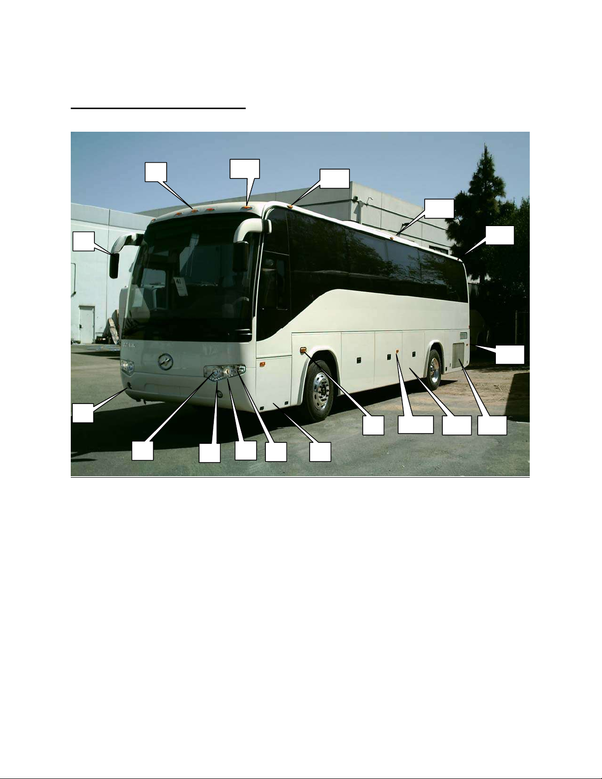
FRONT AND STREET SIDE
2
3
4
1
5
17
16
15
14
13
11
6
7 8
129
1. Front Identification Lamps (Yellow) 9. Front Side Turn Signal
2. Side View Mirrors (Left & Right) 10. Side reflector / marker lamp (Yellow)
3. Fog Lights 11. Luggage Compartments (3), Streetside
4. High Beam Headlights 12. Radiator Access Door
5. LED Parking Lamps 13. Side reflector / marker lamp rear (Red)
6. Low Beam Headlights 14. Side Marker Lamp, Rear (Red
7. Front Park / Turn Lamps 15. Side Marker Lamp, Center (Yellow )
8. Main Electrical Compartment 16. Side marker Lamp, Front(Yellow)
17. Front Clearence lamp, Front(Yellow)
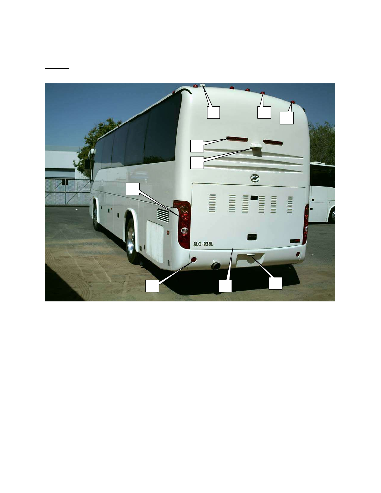
REAR
EXTERIOR COMPONENTS
3
9 8
7
1
2
4
5
6
1. High-Mounted Brake Lights 4. Rear red reflectors
2. Rear View Camera 5. Engine Compartment Door
3. Rear Lamp Assemblies: 6. Rear License Bracket & Lamp
Taillights 7. Rear Clearance Lamps (Red)
Turn Signals 8. Rear Identification Lamps (Red)
Back-Up (Reverse) Lamps 9. Vent ( lavatory-equipped models)
Brake Lights
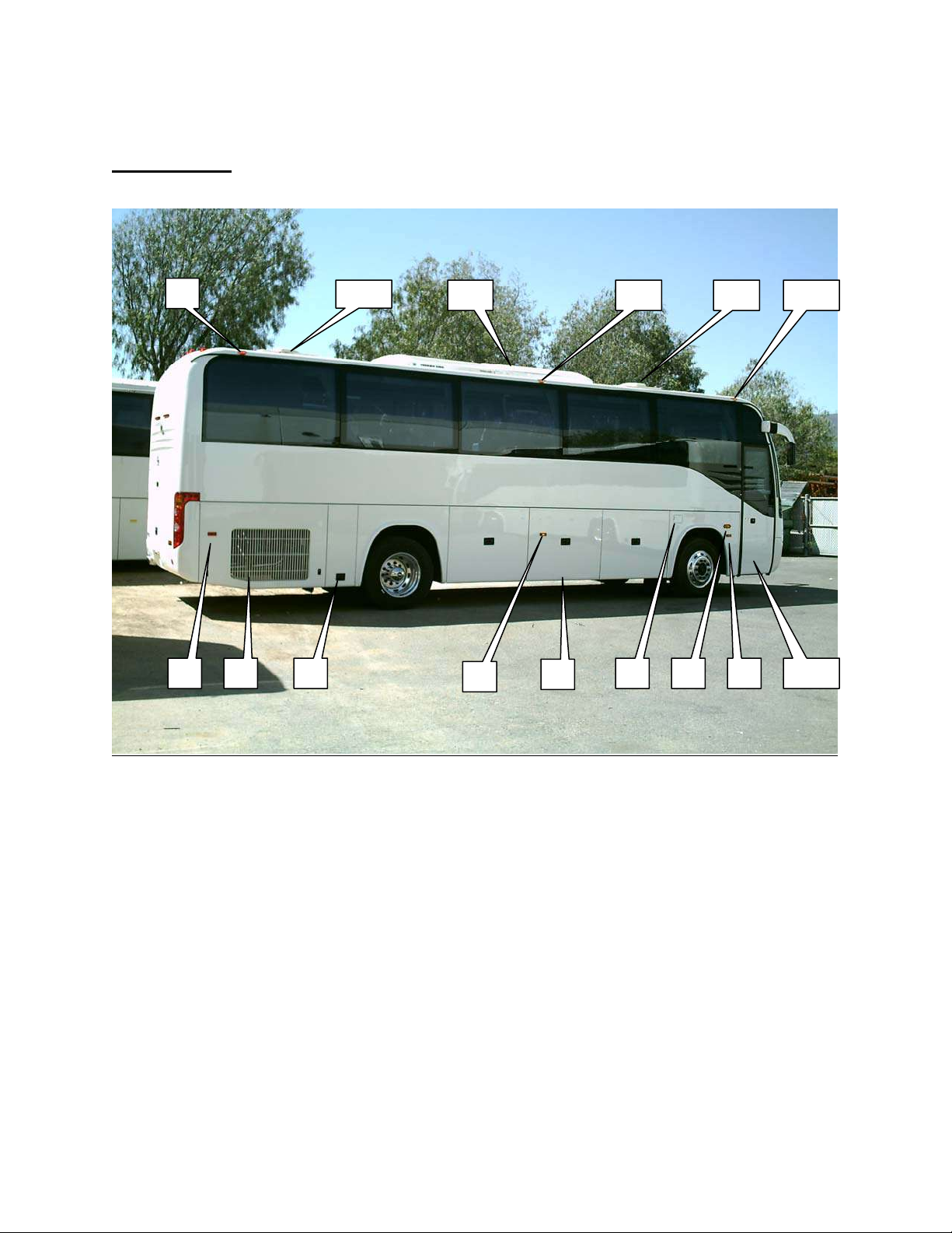
CURB SIDE
EXTERIOR COMPONENTS
1
2 3 4
14 13 12 11
5
6
9 87 10
1. Side marker Lamp, rear (Red) 9. Reflector / marker , Front (Yellow)
2. Reflector / marker , Rear (Red) 10. Entry Door
3. Preheater Compartment Door 11. Side marker Lamp, Front (Yellow)
4. Battery Compartment Door 12. Roof Hatch w/Fan, Forward
5. Reflector / marker , Center (Yellow) 13. Side marker Lamp , Center(Yellow)
6. Luggage Compartments (3), Curbside 14. Roof A/C Unit
7. Fuel Filler Door 15. Roof Hatch w/Fan, Aft
8. Side Turn Signal, Front
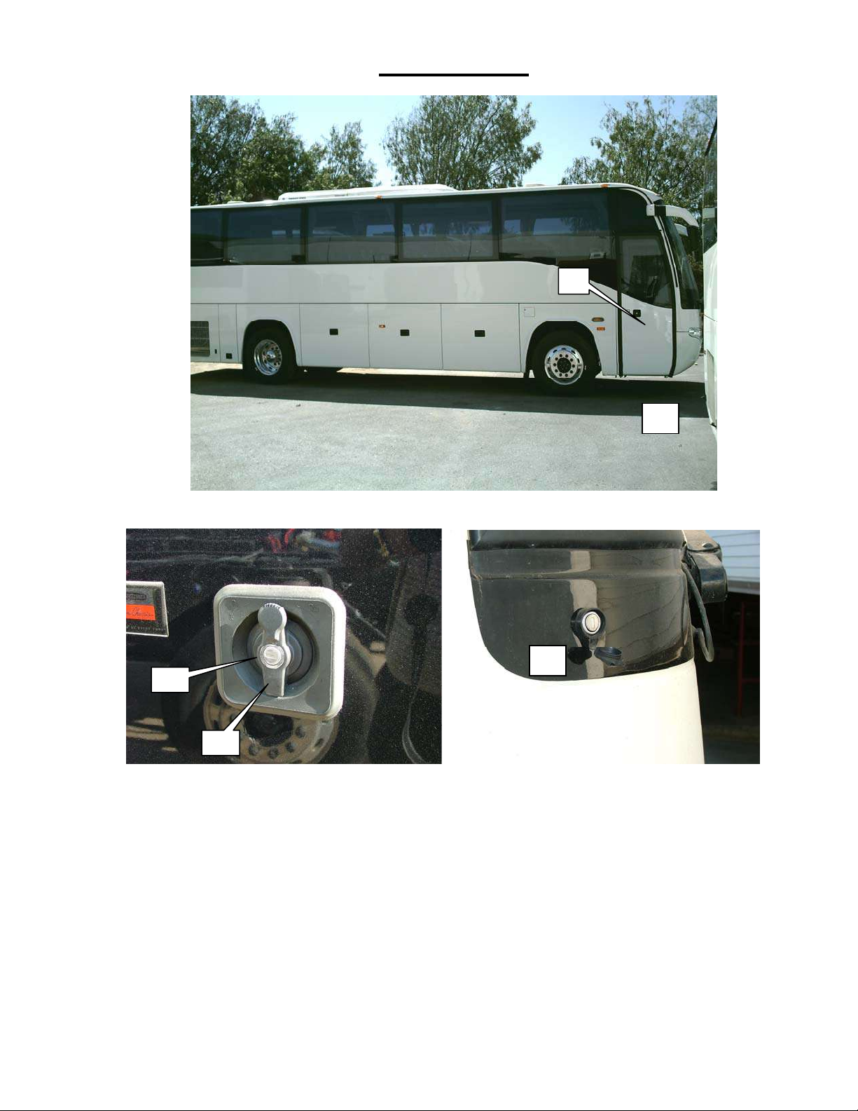
ENTRY DOOR
1
Main Entry Door (1) and Door Lock (2)
4
The entry door may be locked and unlocked manually by inserting the door key into the door key switch
(3), turn the key to the right (clockwise) then turn the door handle (2) to the left (counterclockwise) to
unlock. Turning the handle to the right (clockwise) will lock the door . Turn the key to its original position
and remove the key.
When the door is unlocked, you can opened it or closed it, through the use of the keychain remote control
provided with the vehicle or by inserting the door key into the door key switch (4). This remote is a
battery-powered radio-frequency device that transmits a short-range signal to the vehicle’s door open /
close mechanism. See next page for details of operation.
NOTE: The use of the Key Fob or Key Operated Entry Switch DOES NOT lock or unlock the door.
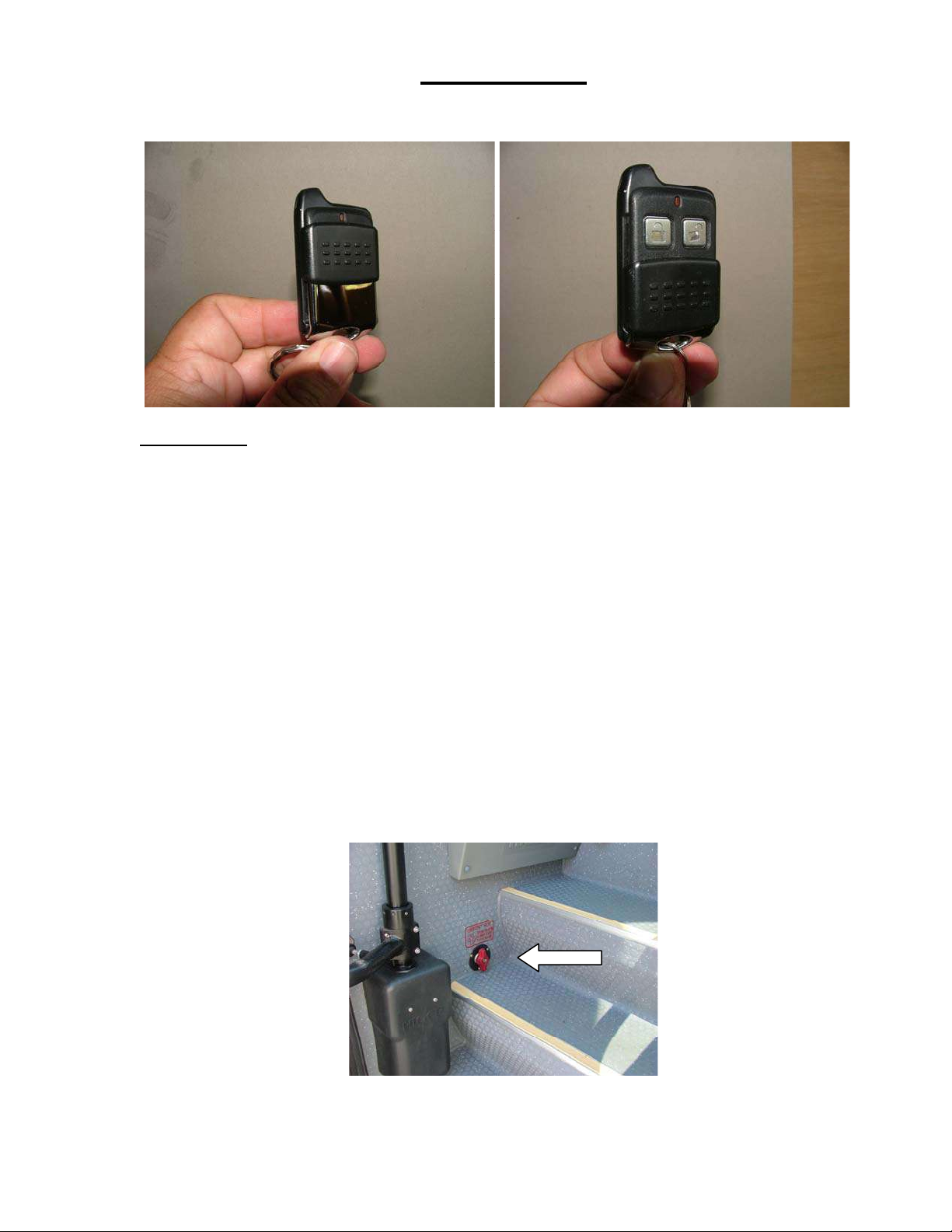
ENTRY DOOR
(Continued)
Door Remote
The door remote control unit has two functions – CLOSE and OPEN.
To access the function buttons, slide the protective cover downward to expose the two buttons. Press the
right (UNLOCK) button once to open the door.
To close the door, press the left (LOCK) button once.
Each time either button is pressed, the red LED at the top of the remote will light. Should the lamp fail to
illuminate when the buttons are pressed, the battery will need to be replaced. The door can only be
locked or unlocked manually with the key .
To replace the remote battery, carefully pry open the side of the remote case. The battery (#2032) is
located in the front (button side) of the case interior. Remove the old battery and fit the replacement cell
into the battery cavity with the positive (+) side of the battery facing downward. Press the case halves
back together and press a button to check function.
EMERGENCY DOOR RELEASE
In an emergency, the door may be released from the interior of the vehicle by turning the red emergency
air release knob clockwise (rigthwise). The air release valve is located above the first step on the curbside
of the bus.
Note: An other manual door release valve is located underneath the vehicle next to the step.
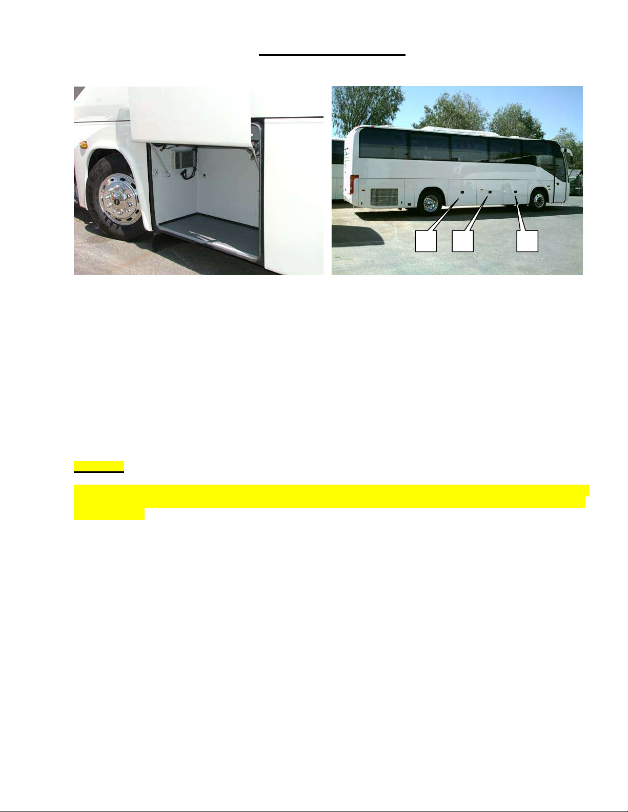
CARGO STORAGE
3 2 1
Front Streetside Cargo Compartment Curbside Cargo Compartment Doors
Three (3) doors on each side of the bus access the cargo / storage compartments.
The forwardmost doors on each side are smaller separate compartments from the large pass-through
compartment that is accessed by the center and rear doors on each side.
The forward curbside cargo compartment contains the tools for changing the spare tire. the forward street-side
compartment house electrical components and the windshield water reservoir.
To open the compartment doors, pull out and up on the door handle and allow the door to rise upward.
CAUTION:
When closing the doors, BE SURE to keep fingers away from the door edges and inner frame. Stand slightly back
from the door and press downward on the outer face of the door to close. The door edges can be pinch points for
hands and feet.
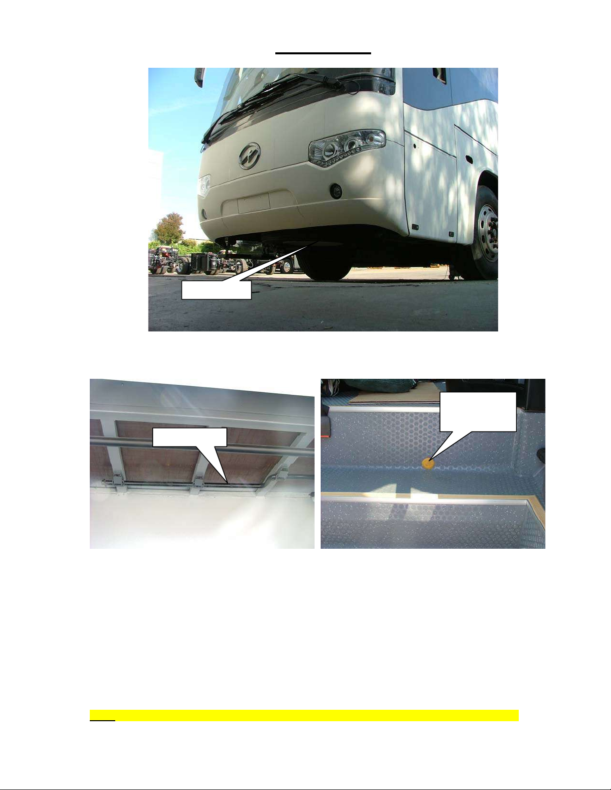
SPARE TIRE
SPARE TIRE
Spare Tire Location (1)
The spare tire is located underneath the vehicle, behind the front bumper.
TIRE GEAR
BOX ACCESS
TIRE CRANK
To access the tire, it must be lowered from its stowed position. The tire is secured in it’s location by two
1- 5/16” Gr 8 nuts and the gearbox chain. Once the nuts are removed, the tire hangs on the chain
mechanism. A crank is used to turn the mechanism and lower the tire.
Lower the spare tire by removing the crank from its stowed position in the forward curbside storage
compartment. Remove the gearbox access port cover at the step below the driver’s seat. Insert the
pinned end of the crank through the hole and into the mechanism receptacle. Remove the1-5/16” security
nuts then turn the crank counterclockwise (left) until the tire is on the ground. Remove the chain end from
the center of the wheel and bring the tire out and away from the vehicle.
Reverse the above steps to stow a tire under the vehicle.
Note: Make sure the tire is stowed securely (not loose and nuts tight) before driving away.

3- INTERIOR COMPONENTS
Sunliner Coach - Corona, California U.S.A.
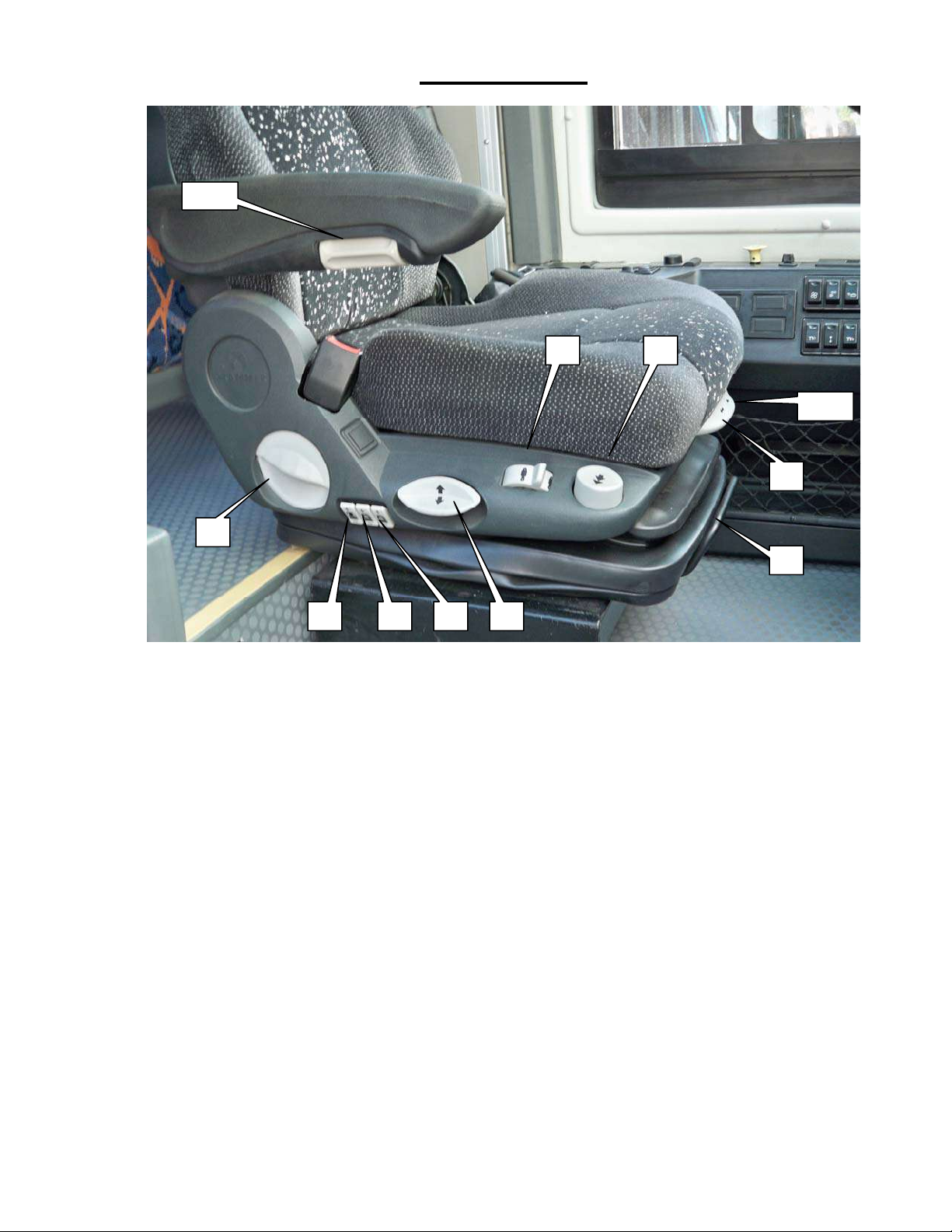
DRIVER SEAT
DRIVER SEAT CONTROLS
The driver’s seat is a pneumatically-adjustable air-suspension seating system that will accommodate a
wide variety of operator physiques and that can be adjusted for extreme comfort by most users.
When getting ready to operate the vehicle for the first time, set the seat controls for best viewing height,
and then proceed to adjust the auxiliary functions such as seatback angle, cushion rake angle, lumbar
support, and suspension stiffness. Always set the seat for the safest and most comfortable position for
operating the vehicle and being able to access all controls and pedals.
1. Seatback Angle Adjuster – pull upward, adjust seat then release.
2. Side Bolster Adjustment – Increases or decreases the side bolster stiffness
3. Lumbar Support Adjustment – Center of back
4. Lumbar Support Adjustment - Upper and lower back
5. Seat Height Adjustment – Push upward to raise seat height, downward to lower.
6. Suspension Stiffness – Slide backward to soften suspension, forward to stiffen.
7. Air Lock / Release – Push downward to deflate seat.
8. Seat adjustment forward / backward – pull upward, adjust seat then release handle.
9. Seat bottom adjustment forward /backward- pull upward, adjust seat then release.
10. Seat inclination adjustment- pull upward, adjust seat then release.
11. Armrest Adjuster – Rotate knob to achieve proper armrest angle.

DASHBOARD
The instrument cluster, steering wheel, switch cluster, and warning lamp cluster
are located directly in front of the driver. This area comprises the main information
and control center for the operator.
2 3
1
7
8
1. Switch cluster #1 7. Steering wheel
2. Instrument Cluster 8. Multifunction stalk
3. Warning lamps cluster
4. Rear view camera monitor
5. Ignition Switch
6. 12V Power socket
4
5
6
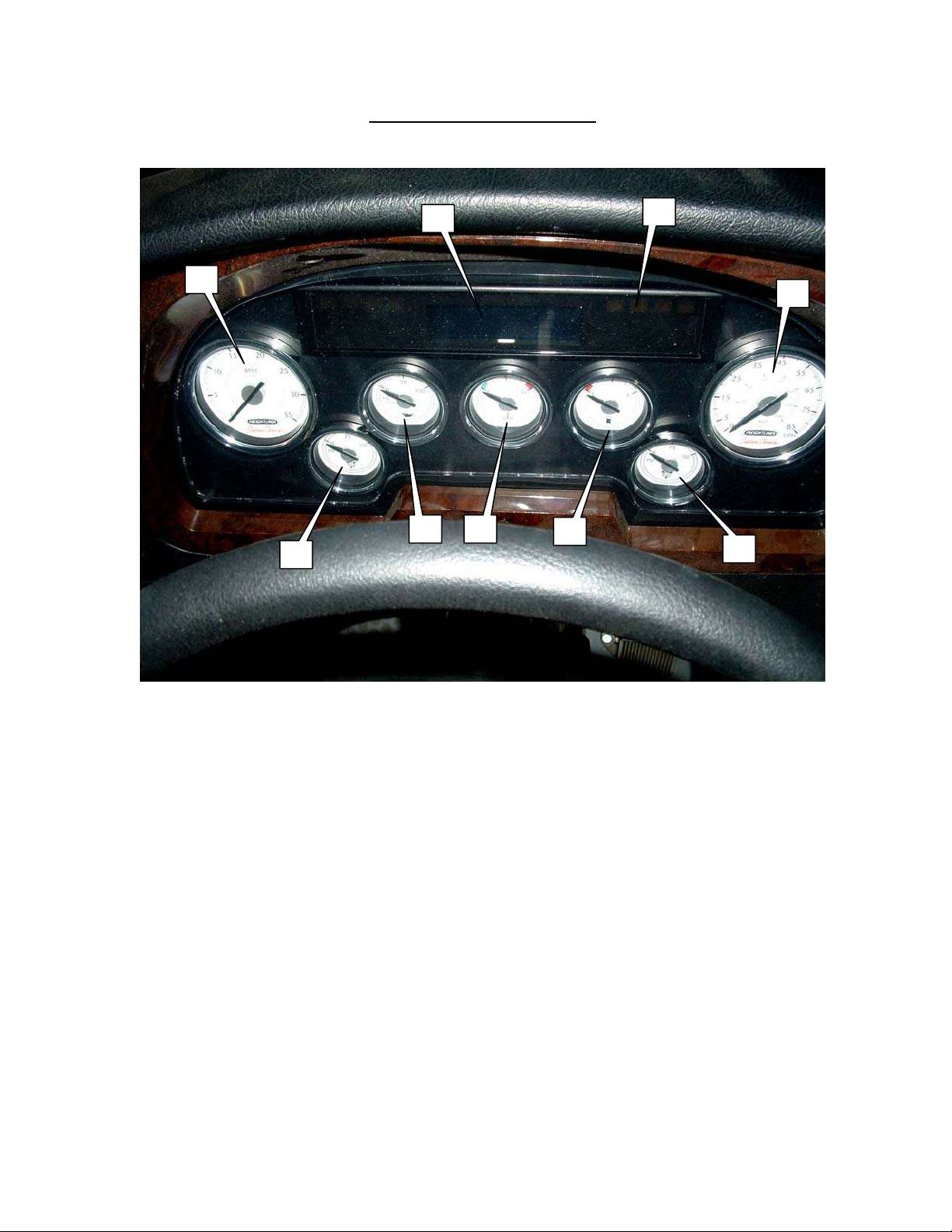
INSTRUMENT CLUSTER
1
2
8
3 4
9
7
5
6
1. Tachometer 7. Speedometer
2. Air Pressure – Main Tank 8. Service Information Display
3. Oil Pressure 9. Warning Lamps (Left & Right sides
of Lamp / Diagnostic panel)
4. Coolant Temperature
5. Fuel Tank Level
6. Air Pressure – Auxiliary Tank

CONTROLS CONSOLE
The driver’s controls console is located on the left side of the driver’s compartment,
below the roadside front window. Most of the major controls for the vehicle are situated
within easy reach of the operator at this location.
4
5
3
2
1
6
7
8
9
10
11
12
1. Interior climate controller (A/C) 7. Switch clusterl #2
2. Parking Brake 8. Side storage pocket
3. Service Information Display Menu Switch 9. Luggage compartment lights
4. Transmission shift control 10. Windshield defroster fan and heat
5. Auxiliary heater ON/OFF switch 11. Exhaust brake ON/OFF
6. Mirror controls 12. Cup holder
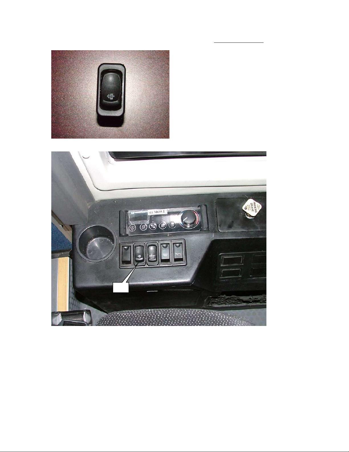
13- Manual regeneration switch ( Exhaust Aftertreatment) Engine EPA 2007
13
A flashing AFTERTREATMENT DIESEL PARTICULATE FILTER lamp indicates that the
aftertreatment diesel filter needs to be regenerated at the next possible opportunity. Engine power
may be reduced automatically.
When this lamp is flashing, the operator should:
1- Change to more challenging duty cycle , such as highway driving , for at least 20 minutes.
2- Perform a stationary regeneration. Follow all instructions from Cummins Owners Manual
ISB 6.7L CM2150 furbished with your Sunliner Coach Bus ( pag, 1-19 to 1-25) bulletin
4021601.
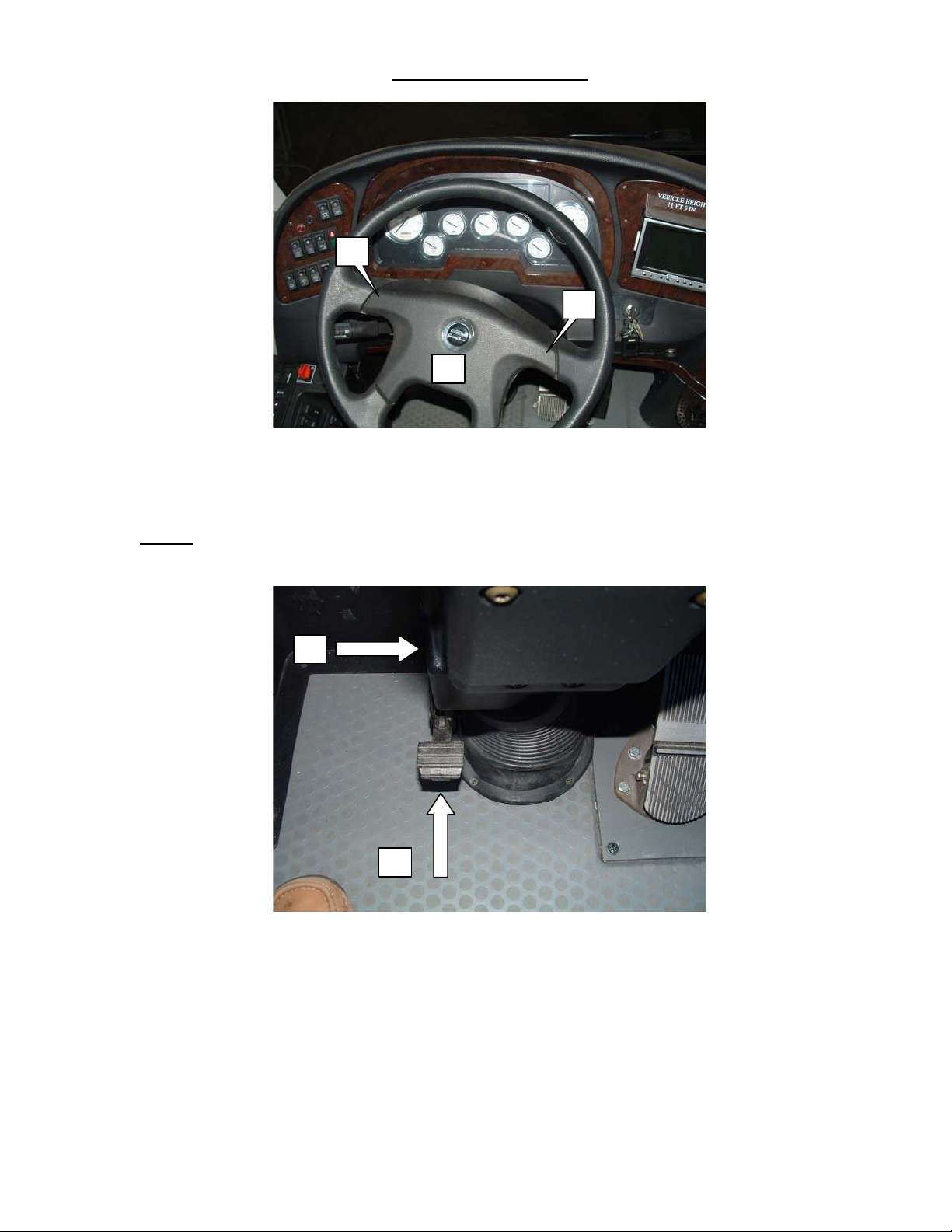
STEERING WHEEL
1
1
2
The steering wheel and column are adjustable for steering wheel angle and overall column
height. The center pad on the steering wheel can be pressed at the upper outside edges (1)
or at the center (2) to activate the horns.
NOTE: Do not turn the steering wheel all the way to the right with the entry door open – the
right front tire will contact the door frame if the wheels are fully turned to the right.
3
4
The steering column height is adjusted with the lever (3) on the left side of the steering
column, below the steering wheel. Pull up on the lever, then pull up or push down on the
steering wheel to set the best height for the operator. Release the lever to lock it back into
position.
Adjust the steering wheel angle by pressing down on the pedal (4) at the base of the
column. Move the steering wheel into the best position and release the pedal to lock into
position.
NEVER adjust the steering while the vehicle is in motion or under power.
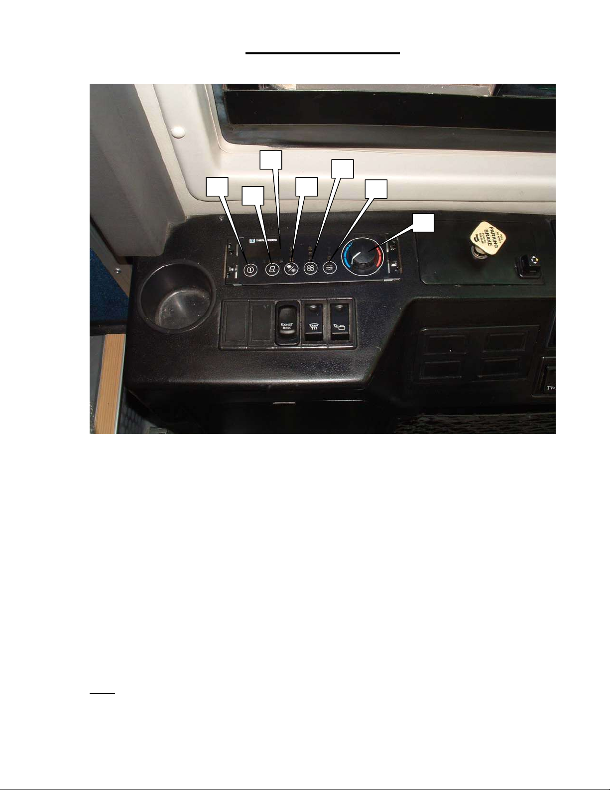
CLIMATE CONTROL
ThermoKing™ Climate Control Panel
The vehicle’s interior environment is managed by the ThermoKing™ Controller located on the side
control console. The controller functions by balancing heat, cooling, airflow, and intake air for maximum
comfort.
1. Power (On / Off)
2. Display Selector (Off / On / Interior Temp. / Exterior Temp.)
3. Display
4. Cooling / Heating Selector (Off / Heat / A/C)
5.
Fan Speed (Low / Medium / High)
6. Vent Position (Closed–Recirculate / 1/2 / Full Open)
7. Temperature Level (Blue zone = colder, Red zone = warmer)
Note: Do not power ON the A/C unless the engine is running.
 Loading...