

STALEX BS-712R Operation Manual

METAL CUTTING BAND SAW
Model: BS-712R
Specifications
Cutting Capacity: 7’’ Round (180mm)
7’’X12’’ Rectangle (180x300mm)
Blade Speed: 86-132-178-260 FPM 60Hz
72-110-148-217 FPM 50Hz
Blade Size: 3/4’’x0.032’’x93’’ (19X0.9X2360mm)
Operation Manual
SAFETY

1. Know your band saw. Read the operator’s Manual carefully. Learn the
operations, applications and limitations as well as the specific potential
hazards peculiar to this band saw.
2. This unit is equipped with a three prong (grounded) plug for your
protection against shock hazards and should be plugged directly into a
property grounded three prong receptacle. Where a two prong wall
receptacle is encountered. It must be replaced with a properly
grounded three prong receptacle in accordance with the National
Electrical Code and Local Codes and Ordinances.
3. Use only 3-wire extension cords that have 3-prong grounding type
plugs.
4. Replace or repair damaged or worn cord immediately.
5. Keep guards in place and in working order.
6. Be especially careful when using band saw in vertical position to keep
fingers and hands out of path of blade.
7. Wear ear protection if exposed to long periods of very noisy shop
operations.
8. Use safety goggles, hardhat and safety shoes. Also use face or dust
mask if cutting operation is dusty.
9. Wear proper apparel. No loose clothing or jewelry to get caught in
moving parts. Do not wear a tie or gloves.
10. Don’t overreach. Keep your proper footing and balance at all times.
11. Secure work. Always use the vise to hold work. Clamp securely. Never
handhold the work with saw in horizontal position.
12. Keep work area clean. Cluttered areas and benches invite accidents.
13. Avoid dangerous environment. Don not use the band saw in damp or
wet location. Keep work area well illuminated.
14. Don’t force tool. It will do the job better and safer at the rate for which it
was designed.
15. Disconnect power cord before adjusting and servicing and before
changing blade.
16. Safety is a combination of operator’s common sense and alertness at
all times when the saw is being used.
17. Never stand on tool. Serious injury could occur if the tool is tipped or if
the cutting tool is accidentally contacted.
18. Check damaged parts. Before further use of the tools, a guard or other
parts that it will operate to assure that it will operate properly
19. And perform its intend function-check for alignment of moving parts;
binding of moving parts, breakage of parts, mounting and any other
conditions that may affect its operation. A guard or other part that is
damaged should be properly repaired or replaced.
20. When moving the saw, ALWAYS have the head lowered to the
horizontal position.
缺电路部分
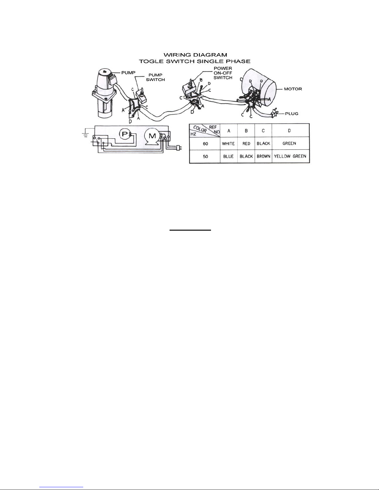
IMPORTANT:
Coolant pump motor voltage must always be the same as machine motor
voltage.
ASSEMBLY
A 3/4 or 1 HP motor split phase or capacitor start is recommended for best
economical performance. Counter clockwise is required. Note that
rotation can be reversed by following directions given on terminal or
nameplate.
1. Assemble the motor Mounting plate to the head using the long bolt.
Note that the flat side of the plate faces up.
2. Assemble the guard plate to the head using the screw and lock washer
and the carriage bolt. Washer and wing nut are used to secure the
motor mounting plate to the guard plate through the slotted hole in the
guard plate. These components also serve to position and lock the
motor in place or proper speed/belt adjustment.
3. Place the spacer over the long bolt and secure it with the nut.
4. Secure the motor to the motor mounting plate with the four volts and
nuts. Note that the motor shaft is placed through the large opening in
the guard plate and must be parallel with the drive shaft.
5. Assemble the motor pulley, the smaller of the two provided to the
motor shaft. Note the larger diameter must be closest to the motor. Do
not tighten the set screw.
6. Assemble the driven pulley, the larger off the two provided to the
protruding drive shaft. Note the smaller diameter must be closest to the
bearing. Do not tighten the set screw.
7. Place the belt into one of the pulley groove and the other end into the
respective grooves of the second pulley.
8. Line up the belt and both pulleys such that the belt is running parallel in
the pulley grooves.

9. Tighten the set screws of both pulleys in this position.
10. Place the belt into proper pulley combination for proper blade speed.
See material cutting chart.
11. Adjust the position of the motor to obtain approximately 1/2’’
depression in the belt when applying pressure with your thumb.
12. Tighten the head screw holding the motor mounting plate to the guard
plate.
13. Connect the electrical harness to the motor terminal box. The motor
should be protected with a time delay fuse or circuit breaker with a
rated amperage slightly greater than the full-load amperage of the
motor.
INSTALLATION
The saw may be mounted on your own bench or stand. The rear end of
the saw must be mounted flush with the rear of the stand or bench to
permit vertical operation for this band saw. A steel your dealer for this
band saw. This stand has punched holes to effect easy assembly to the
base using eight standard bolts.
OPERATION
WORK SET UP
1. Raise the saw head to vertical position.
2. Open vise to accept the piece to be cut by rotating the wheel at the end
of the base.
3. Place work piece on saw bed. If the piece is long support the end.
4. Clamp work piece securely in vise
WORK STOP ADJUSTMENT
1. Loose the thumb holding the work stop casting to the shaft.
2. Adjust the work stop casting to the desired length position.
3. Rotate the work stop as close to the bottom of the cut as possible.
4. Tighten thumb screw.
5. Do not allow the blade to rest on the work while the motor is shut off.
CONVERTING FOR VERTICAL USE
Nothing, slitting, contour work may be done with the saw in the vertical
position in the following manner:
1. Rotate the head to the vertical position.
2. Assemble a 10’’x10’’ table (an option that may be purchased from your
dealer to the guide bar using the screws provided and the guide bar
knob.)
BLADE SPEEDS
When using your band saw always change the blade speed to best suit
the material being cut. The material cutting shaft given suggested settings
for several materials.
4 SPEED MATERIAL CUTTING CHART

Material
Speed F.P.M. Belt Groove Used
60Hz 50Hz Motor pulley Saw pulley
Tool, Stainless alloy
Steels, bearing bronze
86 72 Small Largest
Medium to high carbon 132 110 Medium Large
Low to medium carbon
Steels soft brass
178 148 Large Medium
Aluminum plastic 260 217 Largest Small
BLADE DIRECTION OF TRAVEL
Be sure the blade is assembled to the pulleys so that the vertical edge
engages the work piece first.
STARTING SAW
CAUTION: NEVER OPERATE SAW WITHOUT BLADE GUARDS IN
PLACE.
Be sure the blade is not in contact with the work when the motor is started.
Start the motor, allow the saw to come to full speed, and then begin the
cut by left the head down slowly onto the work. DO NOT DROP OR
FORCE. Let the weight of the saw head provide the cutting force. The
saw automatically shuts off at the end of the cut.
BLADE SELECTION
An 8-tooth per inch, general-use blade is furnished with this metal cutting
band saw. Additional blades in 4,6,8 and 10 tooth sizes are available. The
choice of the blade pitch is governed by the thickness of the work to be
cut; the thinner the work piece, the more teeth advised. A minimum of
three teeth should engage the work piece at all times for proper cutting. If
the teeth of the blade are so far apart that they straddle the work, severe
damage to the work piece and to the blade can result.
CHANGING BLADE
Raise saw head to vertical position and open the blade guards. Loosen
tension screw knob sufficiently to allow the saw blade to slip off the
wheels. Install the new blade with teeth slanting toward the motor as
follows:
1. Place the blade in between each of the guide bearings.
2. Slip the blade around the motor pulley (bottom) with the left hand and
hold in position.
3. Hold the blade taut against the motor pulley by pulling the blade
upward with the right hang which is placed at the top of the blade.
4. Remove left hand from bottom pulley and place it at the top aide of the
 Loading...