

Page 1
TM
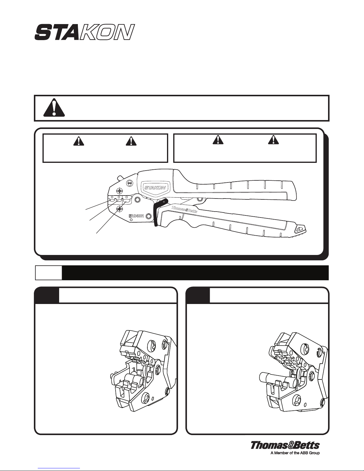
ERG4001 COMFORT CRIMP
®
COMPRESSION TOOL WITH SHURE STAKE® MECHANISM
For Installing Nylon and Vinyl Insulated Terminals,
Disconnects, and Splices 22-10 AWG
IMPORTANT:
information in this manual before operating or servicing this tool.
WARNING
KEEP ALL BODY PARTS AWAY FROM DIE NEST
DURING GAGING OR CRIMPING PROCEDURE.
* Color coded dots red,
blue and yellow, match
insulator and/or splice
for quick identification of
crimp nest.
RED (22-18) NEST
BLUE (16-14) NEST
Read and understand all of the instructions and safety
WARNING
HANDLES ARE NON-INSULATING.
DO NOT CRIMP ON HOT ENERGIZED WIRES.
Model No.
YELLOW (12-10) NEST
In the event the SHURE STAKE® mechanism must be released, please see Figure 5.
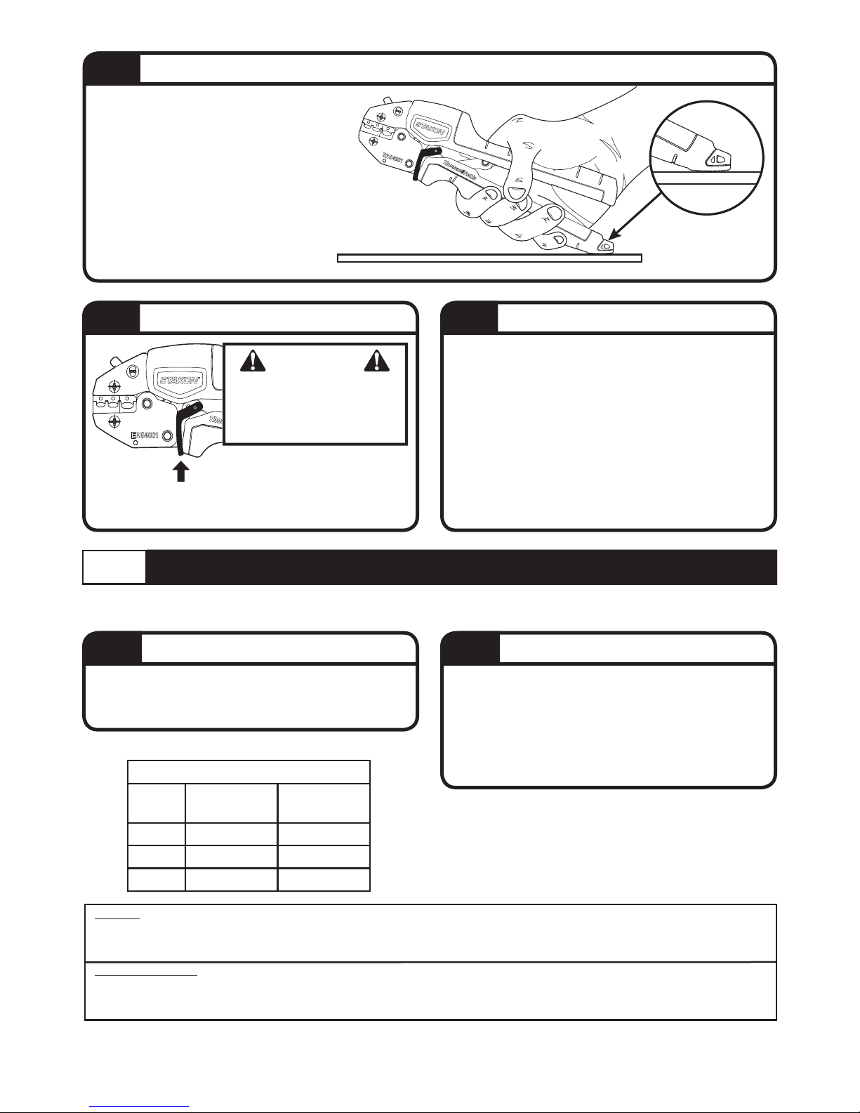
1.0
1.1
1. Open handles fully.
2. Insert terminal into proper nest as shown in Figure 2.
Tongue markings should face up.
3. a) Rotate locator down. Position
terminal so that front of
barrel is flush with locator.
b) As an alternate method without
using the locator, rotate the locator
away from the die nests. Insert
the terminal into the proper nest.
Visually center the teminal within
the nest so that each end of the
insulation protrudes equally
beyond the edges of the nest.
4. Close handles slightly to
secure terminal. Do not deform
terminal.
5. Insert stripped wire.
6. Close handles until SHURE STAKE
mechanism cycle has been completed.
For Use With Insulated Terminals
22-10 AWG
INSTRUCTIONS FOR USE
1.2
*Swing terminal locator away from nest when crimping splices.
1. Open handles fully.
2. Swing locator away from nest.
3. Splices require two crimps.
Position splice in proper nest,
as shown in Figure. 3.
4. Close handles slightly to
secure terminal. Do not
deform terminal.
5. Insert stripped wire.
6. Close handles until
SHURE STAKE
mechanism cycle has
been completed.
7. Repeat steps 3-5 on opposite
®
end of splice.
For Use With Insulated Splices
®
22-10 AWG
Figure 1
Figure 3Figure 2
TA04528 C Page 1 of 2
Page 2
Model No.
1.3
For larger wire and terminal combinations that
require more force to complete the crimp, it
may be useful to press the tool against a flat
work surface (i.e. worktable, floor, etc.) to gain
more leverage. The Crimp Assist® foot helps
stabilize the tool during this type of operation.
Figure 4
CRIMP ASSIST
Model No.
FLAT WORK SURFACE
®
Foot
Place
CRIMP ASSIST® foot
flat on surface for
increased leverage.
1.4
Figure 5
2.0
NOTE: Calibration verification procedure should be performed whenever damage or suspected damage has occurred or as
often as operation conditions warrant.
2.1
Tool must be free of cracks, sharp edges and any other
obvious imperfections that may affect performance of the
tool. Nest area must be free of burrs, dents or scratches.
SHURE STAKE® Mechanism
WARNING
KEEP ALL BODY PARTS
AWAY FROM DIE NEST
DURING GAGING OR
CRIMPING PROCEDURE.
To release the SHURE STAKE
mechanism, push up on the release bar
until the ratchet teeth are disengaged.
®
GAGING VERIFICATION
Visual Inspection
TABLE 1
ERG4001 GAGING REQUIREMENTS
NEST
RED .100 − .103 #22 − #18
BLUE .117 − .120 #16 − #14
YELLOW .149 − .152 #12 − #10
GAGING
MIN. − MAX.
WIRE SIZE
AWG
1.5
1. Remove dust, moisture, and other contaminants
with a clean brush or a soft, lint-free cloth.
2. DO NOT use on objects that could damage the tool.
3. Make certain all pins, pivot points, and bearing
surfaces are protected with a THIN coat of any good
SAE No. 20 motor oil. DO NOT oil excessively.
4. Keep handles closed when not in use to prevent
objects from becoming lodged in the crimping dies.
5. Store tool in a cool, dry area.
2.2
1. Wipe die nest before gaging.
2. Swing locator away from nests. (Gages are to be
inserted on this side.)
3. Close handles until SHURE STAKE® mechanism just trips.
4. Using gage pins, insure that each nest meets the gaging
requirements as specified, in Table 1.
For parts, service, repair and
calibration, contact the Thomas & Betts
Tool Service Center at 1-800-284-TOOL (8665).
Maintenance
Gaging Procedure
WARRANTY: Thomas & Betts sells this product with the understanding that the user will perform all necessary tests to determine the suitability of this product for the user’s
intended application. Thomas & Betts warrants that this product will be free from defects in materials and workmanship for the period stated on the enclosed warranty card. Upon
prompt notification of any warranted defect, Thomas & Betts will, at its option, repair or replace the defective product. Misuse, misapplication or modification of Thomas & Betts
products immediately voids all warranties.
Limitations and Exclusions: THE ABOVE WARRANTY IS THE SOLE WARRANTY CONCERNING THIS PRODUCT, AND IS IN LIEU OF ALL OTHER WARRANTIES EXPRESS OR IMPLIED,
INCLUDING BUT NOT LIMITED TO ANY IMPLIED WARRANTY OF MERCHANTABILITY OR FITNESS FOR A PARTICULAR PURPOSE, WHICH ARE SPECIFICALLY DISCLAIMED. LIABILITY FOR
BREACH OF THE ABOVE WARRANTY IS LIMITED TO COST OF REPAIR OR REPLACEMENT OF THE PRODUCT, AND UNDER NO CIRCUMSTANCES WILL THOMAS & BETTS BE LIABLE FOR
ANY INDIRECT, SPECIAL, INCIDENTAL OR CONSEQUENTIAL DAMAGES.
Thomas & Betts Corporation
Memphis, Tennessee
www.tnb.com
TA04528 C Page 2 of 2© 2013 Thomas & Betts. All Rights Reserved.
 Loading...