

Stairville LED-Commander 16/2 User Manual
LED-Commander 16/2
DMX controller
user manual

Musikhaus Thomann
Thomann GmbH
Hans-Thomann-Straße 1
96138 Burgebrach
Germany
Telephone: +49 (0) 9546 9223-0
E-mail: info@thomann.de
Internet: www.thomann.de
20.02.2018, ID: 251852 | SW V1.2 (V4)
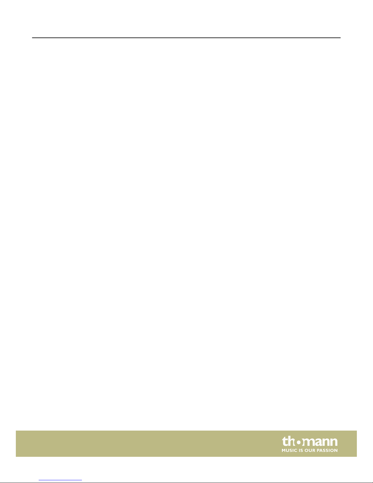
Table of contents
1 General notes............................................................................................................................ 4
2 Safety instructions................................................................................................................. 5
3 Features....................................................................................................................................... 6
4 Installation................................................................................................................................. 7
5 Starting up................................................................................................................................. 8
6 Connections and operating elements.......................................................................... 9
7 Operation................................................................................................................................. 13
8 Technical specifications.................................................................................................... 22
9 Protecting the environment........................................................................................... 23
Table of contents
LED-Commander 16/2
3
1 General notes
This user manual contains important information on safe operation of the device.
Read and follow all safety notes and all instructions. Save this manual for future reference. Make sure that it is available to all persons using this device. If you sell the
device, include the manual for the next owner.
Our products are subject to a process of continuous development. We therefore
reserve the right to make changes without notice.
This section provides an overview of the symbols and signal words used in this user
manual.
Signal word Meaning
DANGER! This combination of symbol and signal word indicates
an immediate dangerous situation that will result in
death or serious injury if it is not avoided.
NOTICE! This combination of symbol and signal word indicates
a possible dangerous situation that can result in material and environmental damage if it is not avoided.
Warning signs Type of danger
Warning – danger zone.
Symbols and signal words
General notes
DMX controller
4

2 Safety instructions
This device is intended to be used to control spot lights, dimmers, light effects,
moving heads or other DMX-controlled devices. Use the device only as described in
this user manual. Any other use or use under other operating conditions is considered to be improper and may result in personal injury or property damage. No liability will be assumed for damages resulting from improper use.
This device may be used only by persons with sufficient physical, sensorial, and intellectual abilities and having corresponding knowledge and experience. Other persons
may use this device only if they are supervised or instructed by a person who is
responsible for their safety.
DANGER!
Danger for children
Ensure that plastic bags, packaging, etc. are disposed of properly and
are not within reach of babies and young children. Choking hazard!
Ensure that children do not detach any small parts (e.g. knobs or the
like) from the unit. They could swallow the pieces and choke!
Never let children unattended use electrical devices.
NOTICE!
External power supply
The device is powered by an external power supply. Before connecting
the external power supply, ensure that the input voltage (AC outlet)
matches the voltage rating of the device and that the AC outlet is protected by a residual current circuit breaker. Failure to do so could result
in damage to the device and possibly the user.
Unplug the external power supply before electrical storms occur and
when the device is unused for long periods of time to reduce the risk of
electric shock or fire.
NOTICE!
Risk of fire
Do not block areas of ventilation. Do not install the device near any
direct heat source. Keep the device away from naked flames.
NOTICE!
Operating conditions
This device has been designed for indoor use only. To prevent damage,
never expose the device to any liquid or moisture. Avoid direct sunlight,
heavy dirt, and strong vibrations.
Intended use
Safety
Safety instructions
LED-Commander 16/2
5

3 Features
n 16 devices controllable via DMX-512
n
2 × 8 memory slots each for scenes and chases
n
Faders for fade and scene time and speed, dimmer etc.
n
Operation modes: automatic, sound controlled and manual
n
Blackout and Full-on-function
n
Separate channel assignment
n
Backup and firmware update via USB
n
USB port for desk light
n
19" housing, 4 RU
Features
DMX controller
6
4 Installation
Unpack and carefully check that there is no transportation damage before using the
unit. Keep the equipment packaging. To fully protect the device against vibration,
dust and moisture during transportation or storage use the original packaging or
your own packaging material suitable for transport or storage, respectively.
The unit has been designed for rack mounting in a standard 19-inch rack. It occupies
four rack units (RU).
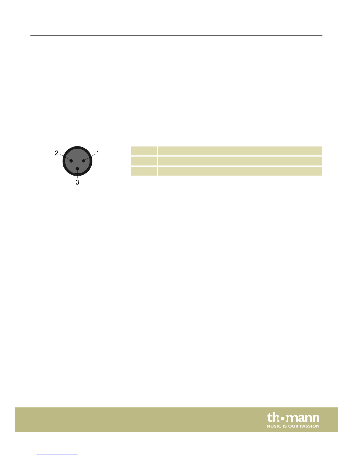
A 3-pin XLR socket is used as DMX output. The following diagram and table show the
pin assignment of the XLR socket.
1 Ground
2 DMX data (–)
3 DMX data (+)
Rack mounting
DMX connection
Installation
LED-Commander 16/2
7
5 Starting up
Create all connections while the device is off. Use the shortest possible high-quality
cables for all connections. Take care when running the cables to prevent tripping
hazards.
Connect the included power adapter to the 9V connector of the unit and then plug
the power adapter into a wall outlet.
Turn on the device using the main switch on the rear panel. After turning the device
on, the display shows the operating mode and the related display LED lights up.
Connecting the power adapter
Turning the unit on
Starting up
DMX controller
8
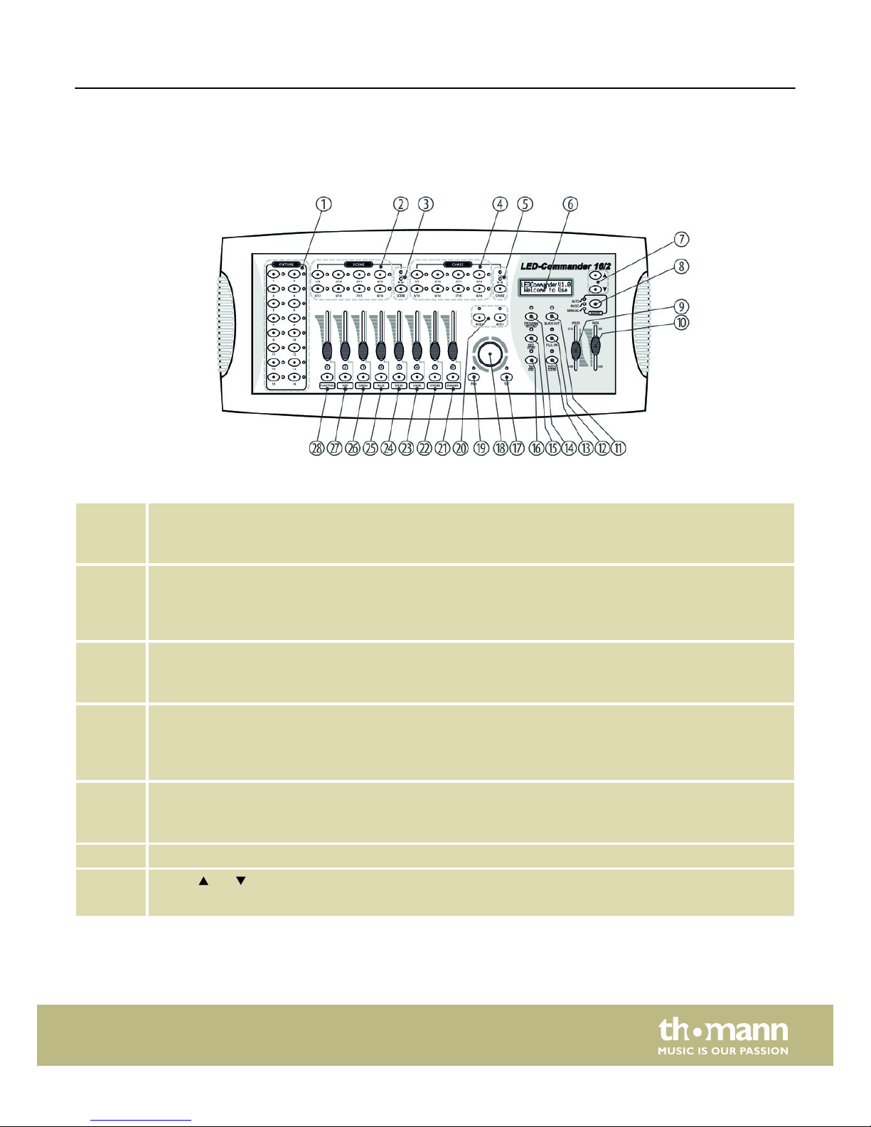
6 Connections and operating elements
1 [FIXTURE]
Buttons 1 to 16 to select the control channels. The associated indicator LED shows whether the respective channel
is switched (LED on) or deactivated (LED off).
2 [SCENE]
Eight buttons with double assignment for switching on / off up to 16 scenes. The indicator LEDs show which
scenes are switched on (LED lights up). Switching between the button groups (banks) 1…8 and 9…16 is done via
the shift button (3).
3 Shift button [SCENE]
Button to switch the SCENE buttons. The two indicator LEDs show which button group (banks) 1…8 (red) or 9…16
(green) is currently active.
4 [CHASE]
Eight buttons with double assignment for switching on / off up to 16 chasers. The indicator LEDs show which
chasers are switched on (LED lights up). Switching between the button groups (banks) 1…8 and 9…16 is done via
the shift button (5).
5 Shift button [CHASE]
Button to switch the CHASE buttons. The two indicator LEDs show which button group (banks) 1…8 (red) or 9…16
(green) is currently active.
6 Device display
7
Buttons and
Navigation buttons to scroll within the display and to select options.
Front panel
Connections and operating elements
LED-Commander 16/2
9
 Loading...