

Stairville DMX512 User Guide
Professional Lighting Technology
User Guide
Please read these instructions carefully before use

7. Fixture Cleaning
The cleaning of internal and external optical lenses and/or mirrors must be carried out
periodically to optimize light output. Cleaning frequency depends on the environment in which
the fixture operates: damp, smoky or particularly dirty surrounding can cause greater
accumulation of dirt on the unit’s optics.
Ÿ Clean with soft cloth using normal glass cleaning fluid.
Ÿ Always dry the parts carefully.
Ÿ Clean the external optics at least every 20 days. Clean the internal optics at least every
30/60 days.
EC Declaration of Conformity
We declare that our products (lighting equipments) comply with the following
specification and bears CE mark in accordance with the provision of the
Electromagnetic Compatibility (EMC) Directive 89/336/EEC.
EN55014-2: 1997 A1:2001, EN61000-4-2: 1995; EN61000-4-3:2002;
EN61000-4-4: 1995; EN61000-4-5: 1995, EN61000-4-6:1996,
EN61000-4-11: 1994.
&
Harmonized Standard
EN60598-1: 2000+ALL:2000+A12:2002
Safety of household and similar electrical appliances
Part 1 : General requirements
2B
.
TABLE OF CONTENTS
1. Safety Instruction
2. Technical Specification
3. Lamp
4. How To Set The Unit
4.1 Control Panel
4.2 Main Function
5. How To Control The Unit
5.1 Master/Slave Built-In Preprogrammed Function.
5.2 Easy Controller
5.3 Universal DMX Controller
5.4 DMX512 Configuration
5.5 DMX512 Connection
6. Troubleshooting
7. Fixture Cleaning
1. Safety Instruction
Please read carefully the instruction, which includes important
.
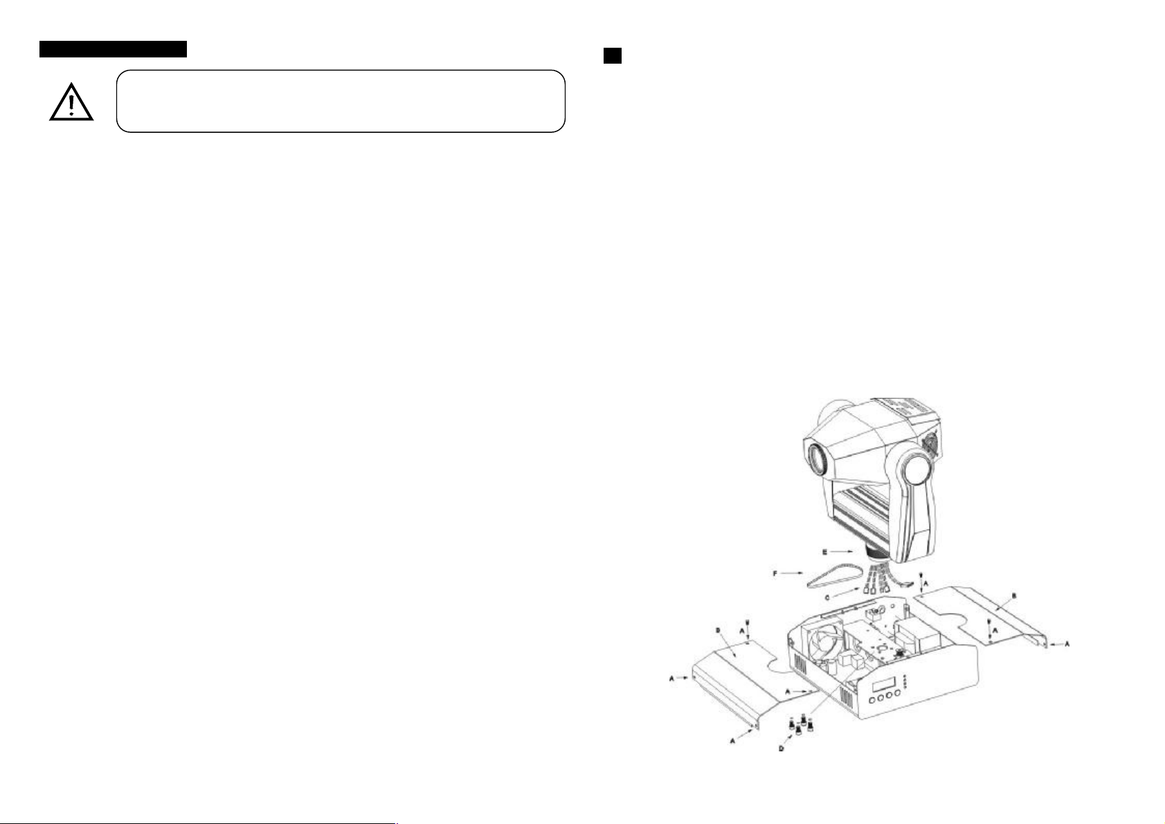
G. If The pan belt is broken
WARNING
l Please keep this User Guide for future consultation. If you sell the unit to another user, be
sure that they also receive this instruction booklet
l Unpack and check carefully there is no transportation damage before using the unit.
l Before operating, ensure that the voltage and frequency of power supply match the power
requirements of the unit.
l The unit is designed for use with the ELC 24V 250W. Do not use any other type of lamp.
l It’s important to ground the yellow/green conductor to earth in order to avoid electric
shock.
l The unit is for indoor use only. Use only in a dry location.
l The unit must be installed in a location with adequate ventilation, at least 50cm from
adjacent surfaces. Be sure that no ventilation slots are blocked.
l Disconnect main power before fuse/lamp replacement or servicing.
l Replace fuse/lamp only with the same type.
l Make sure there is no flammable materials close to the unit while operating as it is fire
hazard.
l Use safety chain when fixes this unit. Don’t handle the unit by taking its head only, but
always by taking its base.
l Maximum ambient temperature is TA: 40℃. Don’t operate it at where the temperature is
higher than this.
l Unit surface temperature may reach up to 85℃. Don’t touch the housing bare-hand during
its operation, and allow about 15 minutes to cool down before replacing bulb or serving, as
the unit could be very hot.
l In the event of serious operating problem, stop using the unit immediately. Never try to
repair the unit by yourself. Repairs carried out by unskilled people can lead to damage or
malfunction. Please contact the nearest authorized technical assistance center. Always
use the same type spare parts.
l Don’t connect the device to any dimmer pack.
l Do not touch any wire during operation as high voltage might be causing electric shock.
information about the installation, usage and maintenance.
1. Turn off the main power.
2. Unscrew all the screws (A) and open the base-housing cover (B).
3. Unplug all the connect wires (C) that from the arm to PC board and ignitor.
4. Unscrew the screws (D) that fix the axis gear (E).
5. Change a new belt (F) by going through all connect wires that from the arm to base, and
through the bridge for correct position.
6. Set up the gear axis to the bridge and screwed it. Note : do not press the belt.
7. Put the belt around the axis gear and motor gear.
8. Plug all the connect wires (C) that form the arm to PC board and ignitor.
9. Adjust the pan home position.
10. Screw the base-housing cover (B).
3B
 Loading...