

Stairs SD Series, SV Series, SVN Series, SC Series, SA Series Installation And Operating Instructions Manual
Submersible Pump
INSTALLATION AND
OPERATING INSTRUCTIONS

2
:
EC DECLARATION OF CONFORMITY
according to the following EC Directives
- Machinery Directive : 2006/42EC/ as amended by 98/37/EC
- Electromagnetic Compatibility Directive : 2004/108/EC
The undersigned, K. T. Hsien, representing STAIRS INDUSTRIAL CO., LTD. / NO.27, LANE
267, HUACHENG RD., SINJHUANG CITY, TAIPEI COUNTY 242, TAIWAN, R.O.C.. manufacturer,
declares that the machine described hereafter:
Electric Pump (1~, 3~, 50HZ, 60HZ)
Model :
Provided that it is used and maintained in accordance with the general accepted codes of good
practice and the recommendations of the instructions manual, meet the essential safety and
health requirements of the
Machinery Directive, and Electromagnetic Compatibility Directive.
For the most specific risks of this machine, safety and compliance with the essential
requirements of the Directive has been based on elements of:
EN 809, EN 60335-1, EN 60335-2-41, EN 61000-6-1:2007, EN 61000-6-3:2007
SD.., SV.., SVN.., SC.., SA.. series
Date: 11.01.2012
Signature
Qualification: Factory Manager
3
SD/SV/SVN/SC/SA Series Submersible Pumps
H
2
H
1
Installation
1.
Check
Insulation resistance
With the motor and cable (excluding the power supply cable) immersed in water, use a Megger to measure
the insulation resistance between ground and each phase of the motor, and again between each phase of
the motor. The Megger should indicate an insulation resistance of not
making the measurement, keep the power supply cable off the ground.
An
auxiliary
the
following before beginning
measurement:
pump
is
recommended
installation.
to
be kept on hand
in
case
of emergency.
less
than
20mega ohms
.
While
2. Installation-
(1) !
(2) This pump must not be installed on its
(3) Install the pump at a location in the tank
(4) If there is a flow of liquid inside the tank,
(5) Do not permit end of discharge piping to
(6) !
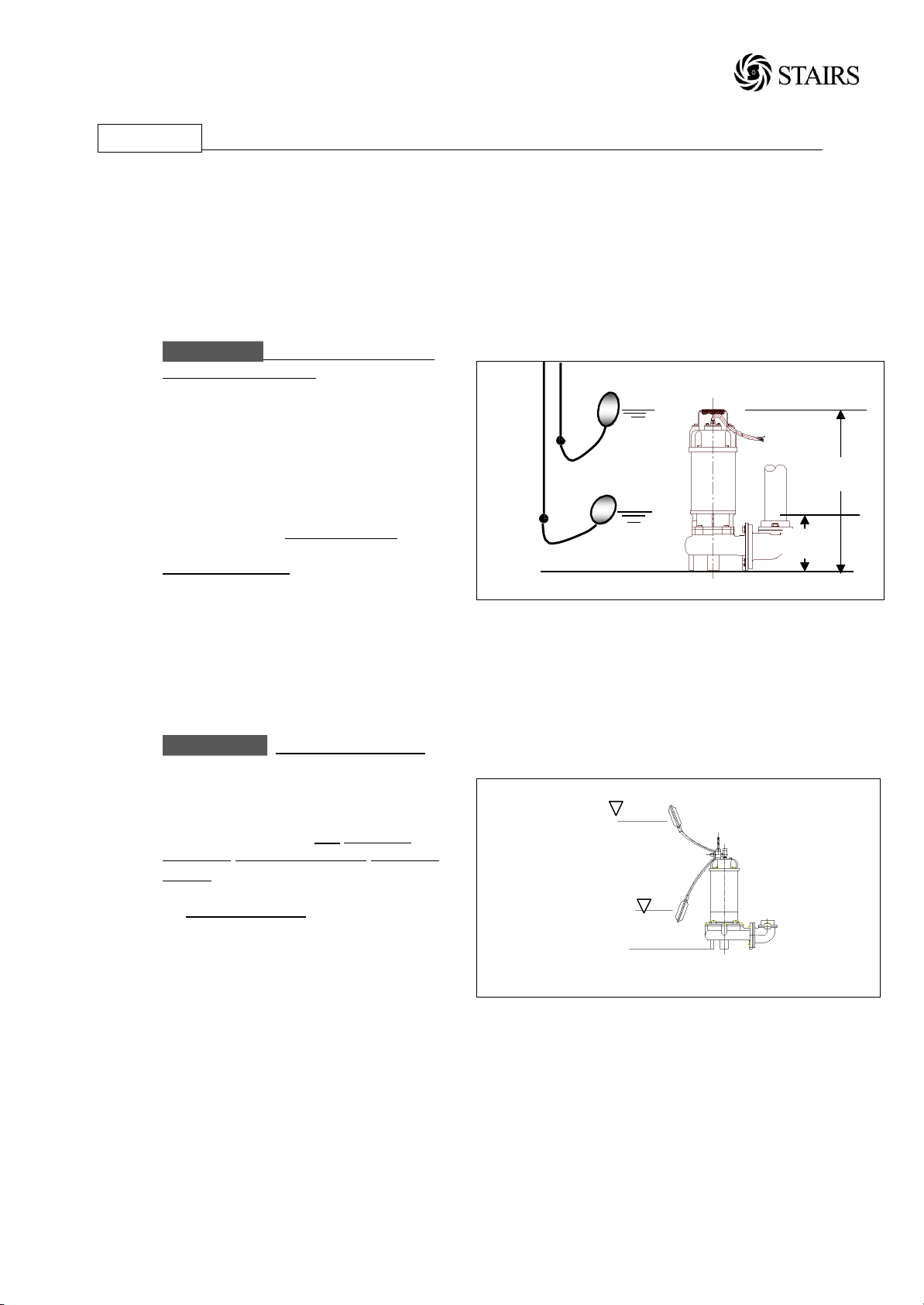
(7) For automatic pumps, install the floats as
WARNING
should cable be pulled while the pump is
being transported or installed.
Attach a chain or rope to the grip and
install the pump.
side or operated a dry condition. Ensure
that it is installed upright on a secure
base.
where there is the least turbulence.
support the piping where appropriate.
Install piping so that air will not be
entrapped. If piping must be installed in
such a way that air pockets are
unavoidable, install an air release valve
wherever such air pockets are most likely
to develop.
be submerged, as backflow will result
when the pump is shut down.
WARNING
have an automatic operating system
bump operating water level near the
minimum operating level as the automatic
cut-off switch incorporated inside the
motor will be activated. To avoid dry
operation, install an automatic operating
system, as shown in Fig-1 and maintain a
safe operating water level.
shown in Fig-2. The pump may not start
if a floats switch touches the wall of the
water tank or the piping. Install the floats
so that this will not happen.
: Under no circumstances
: Non-automatic pumps,
Fig-1
H1: Lowest water level (Motor flange)
H2: Operating water level
This must be above the top of the motor
Operating Water Level
Stop
Water Level
on
off
Fig-2
 Loading...