

Page 1
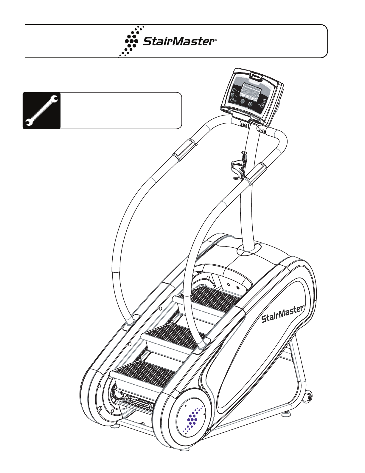
tepMill
S
®
3
Assembly Manual
0300024A
Page 2

Table of contents
_____________________________________________________
Product Specications.......................................................................................... 2
Important Safety Instructions............................................................................... 3
Safety Warning Labels........................................................................................... 5
Before You Start..................................................................................................... 6
Hardware................................................................................................................. 7
Box Contents.......................................................................................................... 8
Assembly................................................................................................................ 9
Contact Information............................................................................................... 16
Product Specications
Model SM3
Dimensions: LWH 46” x 29” x 73” (117 cm x 74 cm x 185 cm)
Unit Weight: 223 lbs (101 kg)
Shipping Package Weight: 298 lbs (135 kg)
Workout Area: 67” W x 84” L (170 cm x 213 cm)
Power Supply: Use only with UL certied power cord provided
Max User Weight: 275 lbs (125 kg)
Regulatory Information
• 2004/108EC, Electromagnetic Compatibility
• 2001/95/EC, General Product Safety Directives
• 2006/95/EC, Electrical Equipment Low Voltage Safety
• Safety: EN957-1, EN957-8, & EN60335-1
• Conducted & Radiated Emissions: EN55014-1, EN55014-2, EN55013 & CISPR 13 & 14.1
• Harmonics: EN61000-3-2
• Flicker: EN61000-3-3
• Immunity: EN55020
2
Assembly Manual
Page 3

Important Safety Instructions
________________________________________________________________________________
This icon means a potentially hazardous situation which, if not avoided, could result in death or serious injury.
Before using this equipment, obey the following warnings:
Read and understand the complete Owner’s Manual and all Warnings on this machine.
• If this machine is being used in a commercial setting, end users may not have access to this Owner’s Manual. It
is the responsibility of the facility to instruct users as to the proper usage of the equipment, as well as making them
aware of potential hazards.
• If this machine is turned off, the staircase will rotate with little resistance. Do not attempt to operate the staircase
when the unit is “OFF”. Otherwise, the machine may be damaged and the warranty voided.
• Keep children away from this machine. Watch them closely when near the machine. Moving parts that appear dangerous to adults may not appear so to children.
• Keep at least 19 inches (50cm) clear area around the machine. This is the recommended safe distance for access
and passage around due to any emergency dismounts from the machine.
• Warn bystanders to keep a safe distance, at least 3 ft (1 m). Do not allow anyone to touch the operator while the machine is in motion. Keep pets, toys and other household items away from the machine.
• Each time before using, examine this machine for loose parts or signs of wear. Pay special attention to the steps.
Contact StairMaster Customer Service for repair information. Use only genuine StairMaster replacement parts.
• Set up and operate your StepMill® 3 unit on a hard, level surface.
• Consult a physician before starting an exercise program. Stop exercising if you feel pain or tightness in your chest,
become short of breath, or feel faint.
• Do not wear loose clothing or jewelry while exercising.
• Workout level speeds may differ depending on user weight.
• Users with different weight may get different speed results.
• Maximum user weight limit: 275 lbs (125 kg). Do not use if you are over this weight.
• Do not over exert yourself during exercise. Do not try to exercise with more resistance than you can physically handle.
Keep body, hair and clothing away from all moving parts.
DANGER - To decrease the risk of electric shock always unplug this machine from the electrical outlet before
cleaning. If this machine is turned off, the staircase will rotate with little resistance. Do not attempt rotation of the staircase
when the unit is “OFF”. Otherwise, the machine may be damaged and the warranty voided.
3
Assembly Manual
Page 4

Important Safety Instructions
________________________________________________________________________________
When you use an electrical appliance, basic precautions must always be followed, including the following:
To decrease the risk of burns, re, electric shock, or injury to persons:
• A machine should never be left unattended when plugged in. Unplug from outlet when not in use, and before you put
on or remove parts.
• This machine is not intended for use by persons (including children) with limited physical, sensory or mental capabilities, or lack of experience and knowledge, unless they have been given supervision or instruction concerning use of
the machine by a person responsible for their safety.
• Close supervision is necessary when this machine is used by, on, or near children, pets, invalids or disabled persons.
• Use this machine only for its intended use as described in this manual. Do not use attachments that are not recommended by the manufacturer.
• Do not operate this machine if it has a damaged cord or plug, if it is not working correctly, if it has been dropped or
damaged, or exposed to water. Contact StairMaster Customer Service.
• Do not operate where aerosol (spray) products are being used or where oxygen is being administered.
• Do not carry this machine by power supply cord or use cord as a handle.
• Keep the cord away from heated surfaces.
• Never drop or put any object into any opening on the machine.
• Do not use outdoors.
• To disconnect, turn all controls to the off position, then remove the plug from outlet. The staircase will rotate with little
resistance when weight is applied to the steps and the machine is not turned on.
4
Assembly Manual
Page 5
Safety Warning Labels
275
125
StairMaster
275
125
_____________________________________________________
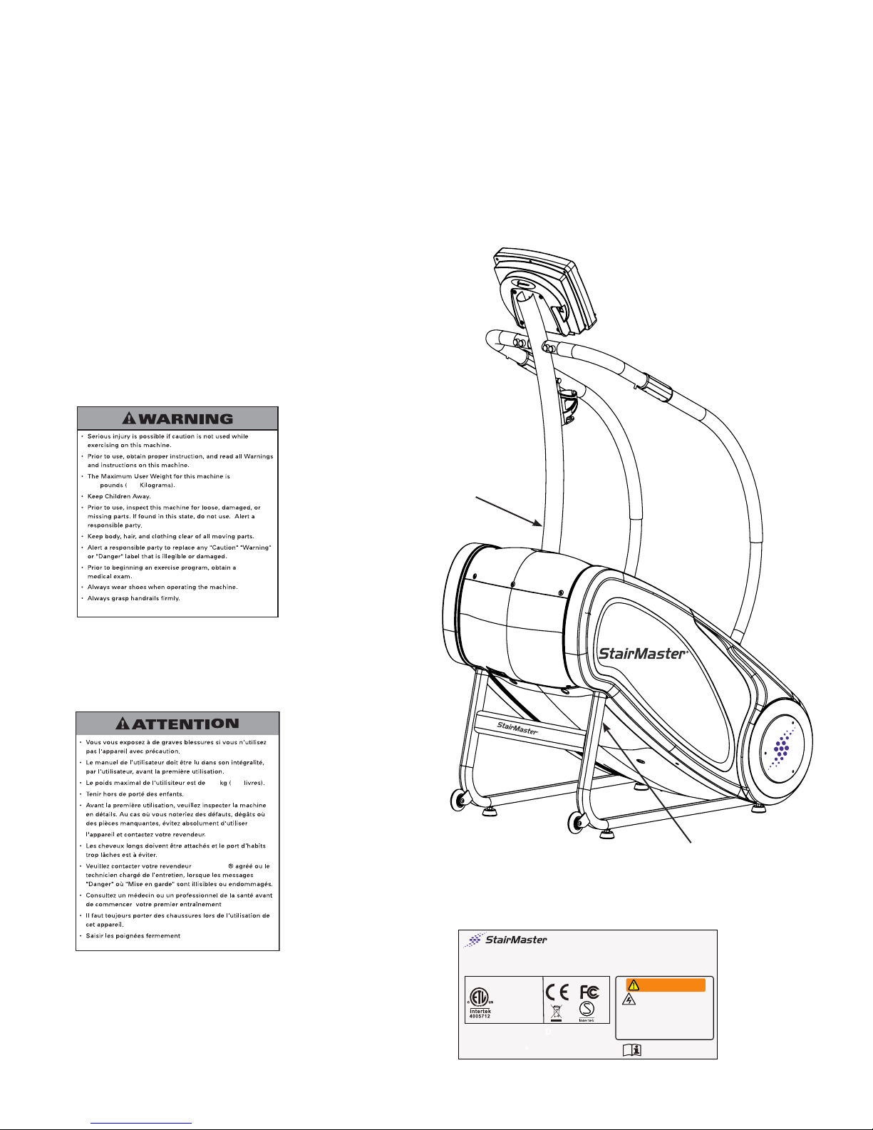
Before using your product: Find and read all warning labels located on the StairMaster® StepMill® 3, prior to using
your product. Be sure to replace any warning label if damaged, illegible, or missing. If you need replacement
labels, contact StairMaster customer service.
Label 1: General Exercise Warning Labels
Label 2: Serial Number Label
(See Figure 1 for locations.)
Figure 1
(1) Warning Labels
(2) Serial Number Label
4400 NE 77th Ave Suite 300
Class HC Fitness Equipment, for Domestic use.
Conforms to STD EN957-1 & EN957-8
SERIAL NO.:
5
Assembly Manual
Core Fitness., Inc
Vancouver WA 98662
CONFORMS TO
UL STD.1647
CERTIFIED TO
CSA STD.C22.2
No.68-09
Product Name:
Model NO.:140001
Rate Input:100-240VAC 1A 50/60Hz
Max User Weight:275Lbs
StepMill 3
723-0251
®
WARNING
SHOCK HAZARD
Do not open cover
Refer servicing to qualified
Personnel only.Disconnect from
Power source before servicing
MADE IN CHINA
Page 6

Before you Start
_____________________________________________________
® ®
IMPORTANT:
Locate the area where you will assemble and use your StairMaster StepMill 3. We recommend you install it on a hard,
level surface. Allow an assembly area of at least 36” (0.91m) on each side and behind the machine. You can put the rear
of the machine closer to the wall during use.
Basic Assembly:
Follow these basic assembly tips when putting together your machine:
1. Collect all the pieces needed for each assembly step.
2. Read through and understand the instructions.
3. Turn all bolts and locknuts to the right to tighten, and the left to loosen.
4. Lightly and carefully lift pieces when attaching. Look through the bolt holes to help guide bolt placement.
5. Two people are recommended to assemble this machine.
6
Assembly Manual
Page 7
Hardware
_____________________________________________________
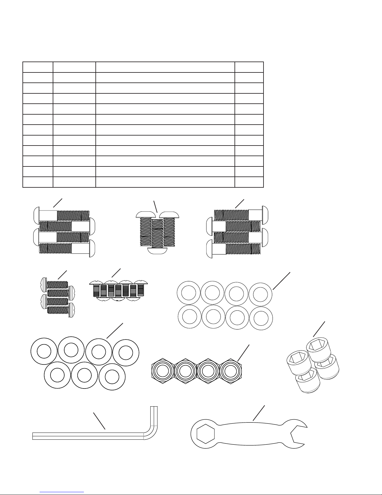
Item # Part # Description Qty
1 723-0242 M10 x 55mm Button Head Screw 4
2 723-0241 M10 x 25mm Button Head Screw 3
3 723-0240 M10 x 45mm Button Head Screw 4
4 40670 1/4-20 x 3/4, Phillips Head W/Lock Washer 4
5 723-0076 M6 x 15 Phillips Head Screw 7
6 21462 16mm Flat Washer 8
7 050-0049 20mm Flat Washer 7
8 731-0363 M10 Nylon Hex Nut 4
9 050-0072 3/8” Nut Cap 4
10 723-0256 6mm Hex Key 1
11 723-0257 Open End Wrench 1
Item 1
Item 4
Item 5
Item 7
Item 2 Item 3
Item 6
Item 9
Item 8
Item 10
HARDWARE NOT TO SCALE
Item 11
7
Assembly Manual
Page 8
Box Contents
_____________________________________________________
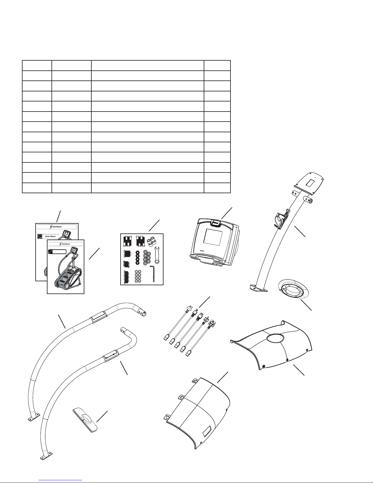
Item # Part # Description Qty
12 030-0025 Owner’s Manual 1
13 030-0024 Assembly Manual 1
14 723-0253 Hardware Card 1
15 723-0229 Console 1
16 723-0171 Mast 1
17 723-0224 Mast Gasket 1
18 723-0197 Handrail, RH 1
19 723-0183 Handrail, LH 1
20 723-0219 Handrail Gasket 2
21 050-0236 Adapter Cord Pack 1
22 723-0212 Mast Shroud 1
23 723-0214 Front Shroud 1
tepMill
S
0300025A
Item 12
®
3
®
3
tepMill
S
Assembly Manual
0300024A
Item 19
Item 13
Item 18
Item 15
Item 14
Item 16
Item 21
Item 17
Item 23
Item 22
Item 20
2-2
8
Assembly Manual
Page 9
Assembly
_____________________________________________________
The following instructions provide direction to assemble the StairMaster StepMill 3. All instructions in the manual are
given with the orientation of standing on a level surface and facing the machine.
(See Figure 1)
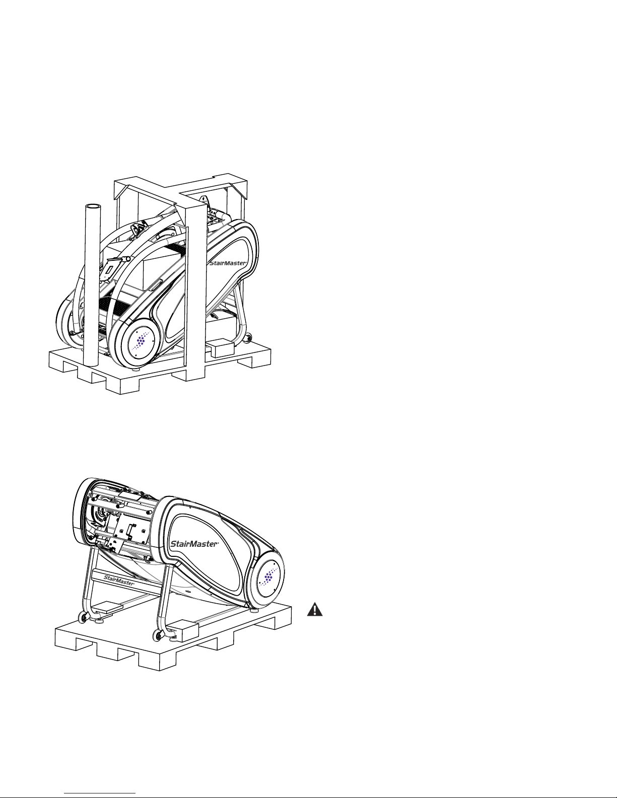
Step 1: Unpacking your SM3
Tools:
• Box Knife
• Hammer or Pry Bar
1-1
1-2
1-3
® ®
Remove the outer cardboard box using the pry bar
to remove staples along the bottom of the box.
Remove the wood bracing forms using the pry bar
or hammer.
Using the box knife, carefully cut the zip ties holding
Mast to handlebars. Place the Mast near assembly
area.
FIGURE 1
FIGURE 2
1-4
Using the box knife, carefully cut the zip ties securing the
handlebars to the machine.
1-5
Remove all boxes on the steps and underneath the machine including the two plastic shrouds.
(See Figure 2)
Step 2: Removal from pallet
• Hammer or Pry Bar
2-1
With a Hammer or Pry Bar, remove the wood securing
the front of the machine to the pallet.
2-2
With the assistance of another person, remove the StepMill machine from the pallet.
Use a second person when performing assembly steps
requiring heavy lifting or awkward movements.
9
Assembly Manual
Page 10
Assembly
_____________________________________________________
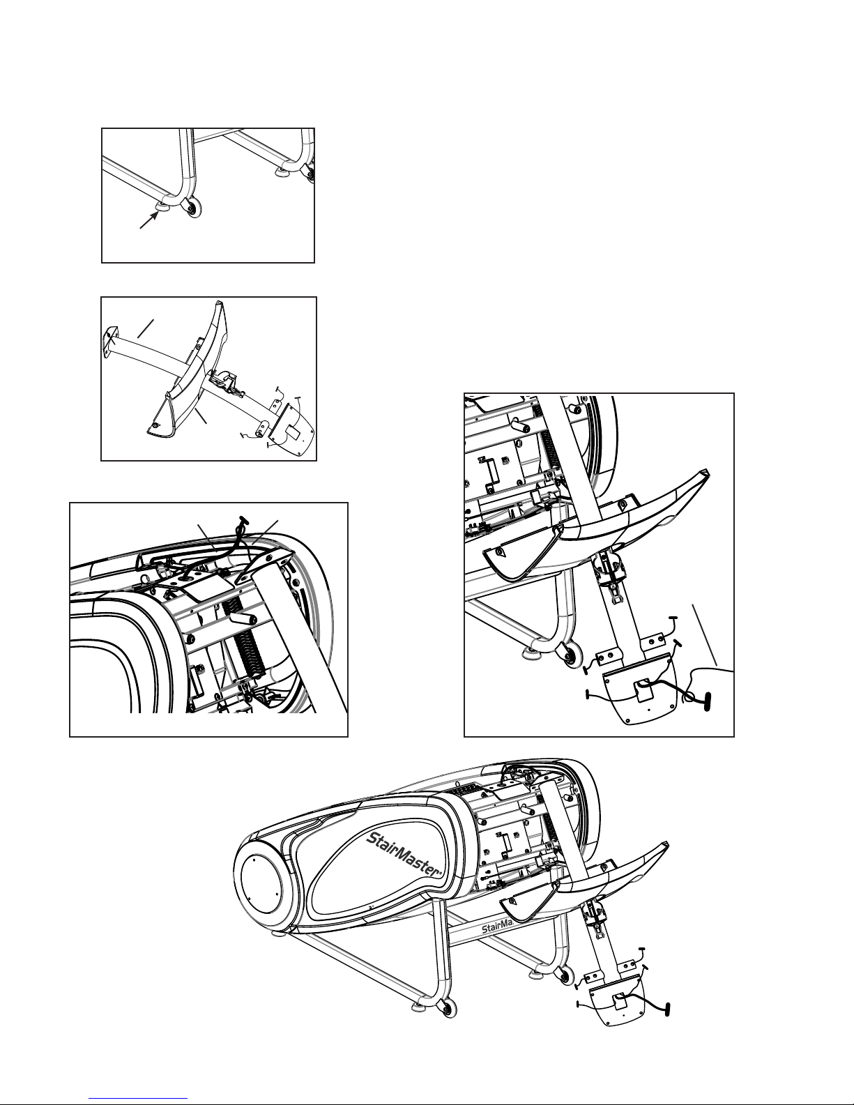
Step 3: Attach the Mast
3-1
Ensure machine is stable and on a level surface. Adjust
any or all four feet if necessary. (Figure 3a)
Slide the Mast Shroud (item 22) onto the Mast (item 16).
Rotate left to raise and right to lower
FIGURE 3a
Item 16
Item 22
FIGURE 3b
3-2
(Figure 3b)
3-3
Using the wire tie within the Mast, wrap the wire tie
around communication cable located at the top mast
mounting area on the machine. (Figure 3c)
3-4
Pull the wire tie at console mounting end of Mast and
feed the communication cable out the square opening of
the Mast exposing the cable. (Figure 3d)
Console Cable
FIGURE 3c
Wire Tie
Wire Tie
FIGURE 3d
10
Assembly Manual
Page 11
Assembly
_____________________________________________________
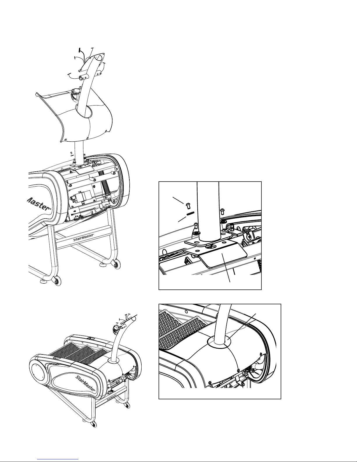
Step 3: Attach the Mast
3-5
Lift the Mast into location and secure to machine frame
with bolts (item 2) and washers (item 6). Keep Mast in
center with mating plate on machine (Figure 3e). Do not
fully tighten the Mast bolts until completing step 3-6.
3-6
Bring Mast Shroud (item 22) into position. Place Mast
Gasket (Item 17) onto Mast Shroud covering the open
space between the Mast and Mast Shroud (Figure 3f).
After verifying t, remove Mast Gasket and slide Mast
Shroud up.
Note: If Mast Gasket does not seat properly, adjust the
Mast by loosening the bolts and re-centering the Mast.
3-7
Fully tighten bolts.
Item 2
Item 6
FIGURE 3e
Mating Plate
Item 17 Fit check
FIGURE 3f
11
Assembly Manual
Page 12
Assembly
_____________________________________________________
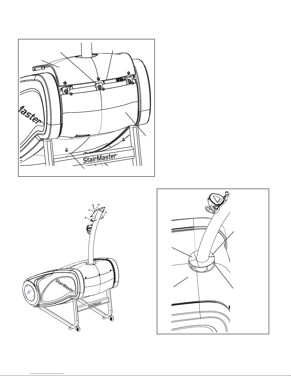
Front Shroud tab for precise alignment with Mast Shroud
Item 22
FIGURE 4a
Flange on Mast Shroud for secure
seal between both shrouds
Item 5
Item 23
Step 4: Attach & Fasten Shrouds
Using screws (item 5), attach Front Shroud
4-1
(item 23) to frame by positioning it into location and allowing it interlock with the Mast
Shroud (item 22) as shown in gure 4a.
Note: Ensure both shrouds seat ush before fully tightening all ve screws.
4-2
Attach the Mast Gasket (item 17) by aligning
the cut away with the Mast Shroud cut out
(Figure 4b).
Item 17
Item 22
Mast Gasket cut away
must align with Mast
Shroud cut out
Mast Shroud cut out
FIGURE 4b
12
Assembly Manual
Page 13
Assembly
_____________________________________________________
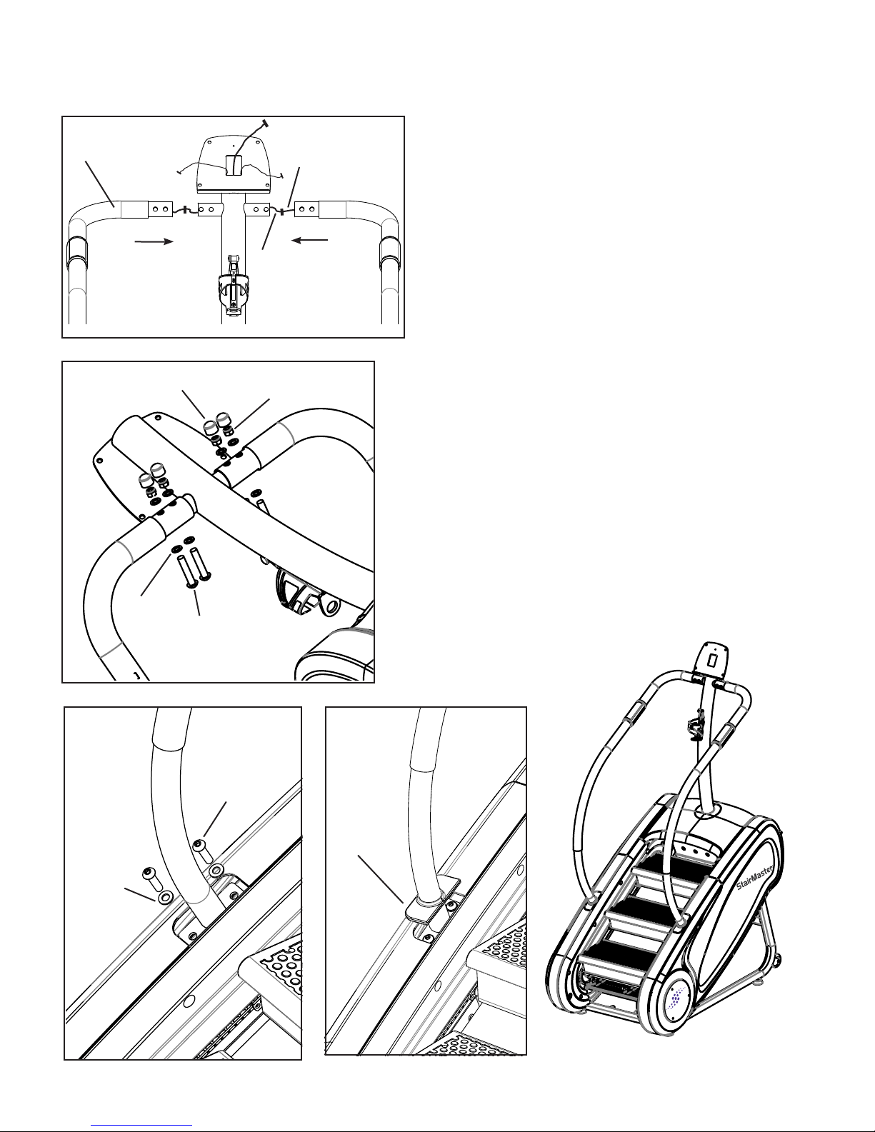
Step 5: Attach the Handrails
Item 19
FIGURE 5a
Item 9 (x4)
Item 8 (x4)
Mast HR
Handrail HR
5-1
Locate Handrail LH (item 19) and position into location
by plugging in the Mast heart rate cable with the handrail
heart rate cable (Figure 5a).
5-2
Position into location by guiding the heart rate cables
into the Mast handrail tube while sliding the Handrail LH
tube over the Mast handrail tube (Figure 5a).
Note: Use caution not to pinch heart rate (HR) cables
while sliding handrails into position.
5-3
Using bolts (item 1), washers (item 6), nuts (item 8), and
caps (item 9), secure the Handrail LH to the Mast (Figure 5b). Do not fully tighten until completing step 5-4.
Note: Use caution not to pinch heart rate cables while
pushing the bolts into location.
5-4
Using bolts (item 3) and washers (item 7), secure the
base Handrail LH to the machine frame (Figure 5c).
Item 7 (x2)
Item 6 (x8)
Item 1 (x4)
FIGURE 5b
Item 3 (x2)
FIGURE 5c
FIGURE 5d
Item 20
Tighten all bolts.
5-5
5-6
Install Handrail Gasket (item 20) (Figure 5d). Ensure
gasket groove is completely within the plastic shrouds.
5-7
Repeat steps 5-1 through 5-6 for Handrail RH (item 18).
13
Assembly Manual
Page 14
Assembly
_____________________________________________________
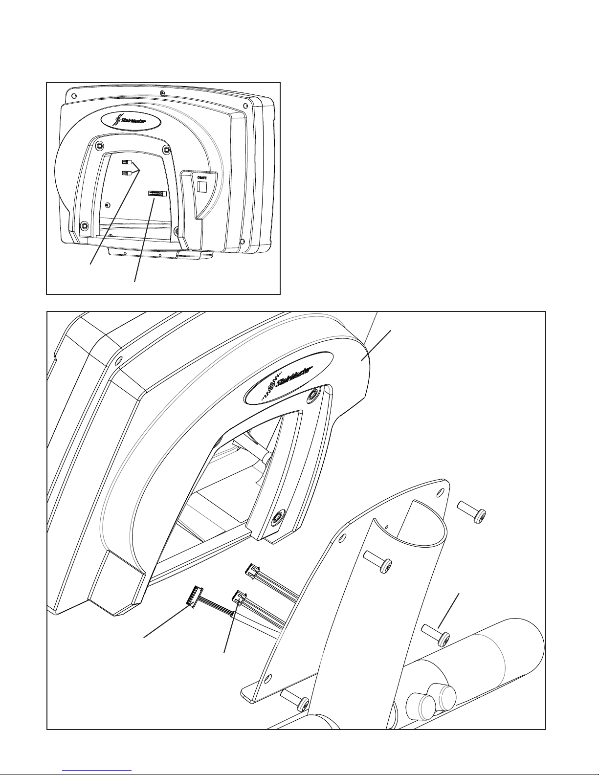
Step 6: Installing the console
6-1
Holding the Console (item 15), connect the Communication cable and Heart Rate cables to the corresponding
locations on the back of the console (Figure 6a, 6b).
6-2
Using screws (item 4), attach the Console to the Mast of
the machine (Figure 6b).
Heart Rate Cable (x2)
Communication Cable
FIGURE 6a
Item 15
Communication Cable
Heart Rate Cable (x2)
FIGURE 6b
Item 4 (x4)
14
Assembly Manual
Page 15
Assembly
_____________________________________________________
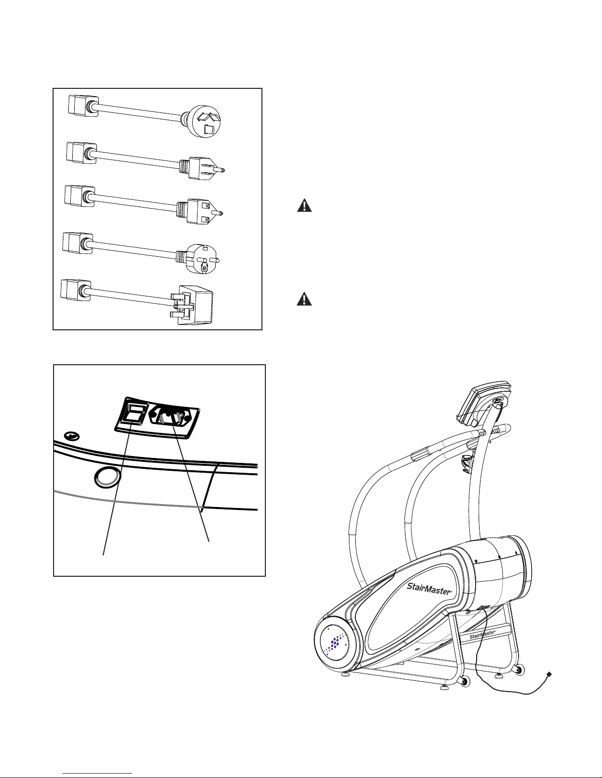
Step 7: Connecting Power to machine
7-1
Select power cord that coincides to the local electrical
standard outlets (Figure 7a).
7-2
Check that the input AC power rating detailed on the serial number decal matches the available power.
7-3
Insert power cord into the power source inlet (Figure 7b)
To reduce the risk of electrical shock, re, and to prevent
severe damage to the machine, use only the power supply approved for use with this equipment. In addition,
your machine must be properly grounded.
Step 8: Final Check
Failure to visually check and test assembly before use
FIGURE 7a
can cause damage to the equipment. It can also cause
serious injury to users and bystanders.
On/Off Switch
Power Source Inlet
FIGURE 7b
8-1
Tighten all hardware.
8-2
Refer to Owner’s Manual for Operating.
15
Assembly Manual
Page 16
Contacts
Contacts
_____________________________________________________
CUSTOMER SERVICE
Tel: 1-888-678-2476
Parts e-mail: [email protected]
Service e-mail: [email protected]
STAIRMASTER
StairMaster
4400 NE 77th Ave, Suite 300
Vancouver, Washington 98662
USA
1-888-678-2476 | www.stairmaster.com
Please supply the serial number of your machine and the date of
purchase when you call StairMaster. Use the space in the boxes below
to write down this information. To
machine, refer to the Safety Warning Label information page.
Serial Number
Date of Purchase
© 2012 Core Fitness, LLC, dba StairMaster. All rights reserved. ™ and ® indicates a trademark or registered trademark. Core Fitness, LLC trademarks
include StairMaster®, StepMill®, and respective logos. 1.888.678.2476, www.stairmaster.com.
d the serial number on your
16
Assembly Manual
 Loading...