

Page 1
®
STEPMILL 7000
OWNER’S MANUAL
Page 2
Printed in the United States.
© 2001 StairMaster® Health & Fitness Products, Inc.
All rights reserved.
Corporate Headquarters
12421 Willows Road N.E., Suite 100
Kirkland, WA 98034
(800) 635-2936
(425) 823-1825
Fax (425) 823-9490
www.stairmaster.com
P/N 22869 - A
© 2001 StairMaster Health & Fitness Products, Inc. StairMaster and Stepmill are registered trademarks
or trademarks of StairMaster Health & Fitness Products, Inc. in the United States and/or other countries.
All other trademarks are trademarks of their respective companies. StairMaster is a Rutledge Capital company.
Page iii
Page 3

WARRANTY
This is to certify that the StairMaster® Stepmill® 7000 PT exercise system is
warranted by StairMaster Health & Fitness Products, Inc. to be free of all defects in
materials and workmanship. This warranty does not apply to any defect caused by
negligence, misuse, accident, alteration, improper maintenance, or an “act of God”.
This warranty is non-transferable from the original owner .
If, within three years from the date of purchase, any part of the StairMaster
Stepmill exercise system should fail to operate properly (except any accessories ), contact
our Customer Service Department to report the problem. When calling, please be
prepared to provide the customer service representative with the following information:
• Your name, customer number, shipping address, and telephone number
• The model and serial number of the inoperable machine
• The date(s) of purchase for the inoperable machine(s)
• Your billing address
This information will ensure that you are the only one ordering parts under your
warranty protection. If warranty replacement parts are shipped to you, you may be
required to return the inoperable part. T o facilitate this process, the following policy has
been established:
• Please call our Customer Service Department to receive a return
materials authorization prior to shipment.
• StairMaster Health & Fitness Products, Inc. will incur all freight
charges for warranty parts ordered for a machine that is less than 45
days old. The parts will be shipped to you via an overnight courier.*
• You are responsible for freight charges on warranty parts for
machines that are more than 45 days old. You will not be responsible
for the return shipment of the inoperable parts.
• Some inoperable warranty parts must be promptly returned to our
Customer Service Department. We will pay the shipping cost for the
inoperable warranty parts. Detailed instructions are included with
each warranty replacement part.
StairMaster Health & Fitness Products, Inc. neither makes, assumes nor
authorizes any representative or other person to make or assume for us, any other
warranty whatsoever , whether expressed or implied, in connection with the sale, service,
or shipment of our products. We reserve the right to make changes and improvements in
our products without incurring any obligation to similarly alter products previously
purchased. In order to maintain your product warranty and to ensure the safe and efficient
operation of your machine, only authorized replacement parts can be used. This warranty
is void if parts other than those provided by StairMaster Health & Fitness Products, Inc.
are used.
* Note: Aerosol products cannot be transported via air .
Page iv
Page 4

PREFACE
The StairMaster® Stepmill® 7000 PT exercise system is a safe, functional, and
effective exercise modality for developing aerobic fitness and increasing the
strength of the major muscle groups of the lower body. It is designed for use by
individuals of all ages and fitness levels. Your purchase of this machine is a
positive affirmation of your commitment to use the best available methods for
enhancing your functional fitness capabilities. In order to derive optimal benefits
from your machine, you should read this manual thoroughly and adhere closely to
the instructions.
WHAT IS IN THIS MANUAL?
Following the information on installation and a brief explanation of how the
Stepmill 7000 PT exercise system works, this manual contains two major
sections. The first section provides an explanation of how the machine should be
used to achieve maximum results. The second section offers instructions and
advice on how to properly maintain your machine. The “Appendix” contains
additional information for the owner.
Throughout this Manual, whenever you are required to enter information into
the console, the console keypad keystrokes are enclosed in [ ]. The names of the
buttons and special console operational modes are shown in capital letters. For
example, your machine is ready for use when the console displays "SELECT
WORKOUT." Press the [MANUAL] button to start the MANUAL exercise
program.
WHAT IS THE STAIRMASTER STEPMILL 7000 PT EXERCISE SYSTEM?
The StairMaster Stepmill 7000 PT exercise system is a vertical climbing
machine with a rotating staircase which provides an aerobic workout equivalent
to climbing stairs, without the impact loads and skeletal trauma common to
most aerobic activities. Regular use of the Stepmill 7000 PT exercise system
strengthens and conditions the heart and the following lower body muscle
groups: gluteals, quadriceps, hamstrings, and calf muscles.
Page v
Page 5

CONTENTS
SAFETY GUIDELINES ......................................................................................... 1
INSTALLATION INSTRUCTIONS........................................................................ 3
BASIC OPERATING INSTRUCTIONS ................................................................ 6
General Guidelines for Safe Operation........................................................... 6
Your First Workout on the StairMaster® Stepmill® 7000 PT
Exercise System ............................................................................................. 7
Basic Instructions for First-Time Users.......................................................... 7
Rest periods .................................................................................................... 8
HEART RATE MONITORING ............................................................................ 1 0
Locked/Non-Locked Option ......................................................................... 10
Error Messages ............................................................................................ 11
TELEMETRY (POLAR®) HEART RATE............................................................. 1 2
Using the Transmitter Belt ........................................................................... 1 2
Maintaining the Transmitter Belt ................................................................ 1 3
7000 PT CONSOLE ............................................................................................. 1 4
The Display Window ....................................................................................1 4
The Numeric Keypad ....................................................................................1 5
The Entertainment Keypad .......................................................................... 15
The Intensity Level Keys.............................................................................. 1 5
The Stop Key ................................................................................................ 1 5
The Workout Statistics ................................................................................ 1 6
The Exercise Program Keypad .....................................................................1 7
The Quick Start Option ............................................................................. 1 7
The Manual Program ................................................................................1 7
The Fat Burner Program ........................................................................... 18
The Aerobic Training Program ................................................................. 1 8
The Speed Intervals Program .................................................................. 1 8
The Constant Heart Rate Program .......................................................... 1 9
The Fitness Test Programs ........................................................................... 2 0
Understanding Submaximal Exercise Testing............................................ 20
Pretest Screening ......................................................................................... 22
The StairMaster Submaximal Fit Test .........................................................2 2
The Firefighter's Stair Climb Tests .............................................................. 25
Page vi
Page 6

CONTENTS
Turning the CPAT Stair Climb Test on ......................................................2 6
Turning the NYCFD Stair Climb Test on................................................... 26
Console Codes .............................................................................................27
MAINTENANCE INSTRUCTIONS ................................................................... 31
Helpful Hints ................................................................................................. 31
Tool List......................................................................................................... 3 1
Maintenance Records ................................................................................. 31
Initial Service ................................................................................................ 3 2
Preventative maintenance ...........................................................................32
Cleaning and Inspecting ....................................................................... 3 2
Lubrication.............................................................................................33
TROUBLESHOOTING ........................................................................................ 36
General Troubleshooting Guidelines ........................................................... 3 6
Troubleshooting the Electrical System ....................................................... 36
The Console Fails to Power Up ............................................................ 3 6
Console Diagnostics Tests........................................................................... 3 9
The Display Test .................................................................................... 3 9
The Keypad Test................................................................................... 3 9
The Serial Port test ............................................................................... 4 0
The Alternator Test ...............................................................................4 0
The Tach Test ........................................................................................ 4 1
Error Reporting...................................................................................... 4 1
The Telemetry (Polar®) Heart Rate Test ............................................... 42
Speed Control Problems.............................................................................. 43
Load Resistor Test ........................................................................................ 47
Tr oubleshooting the Drive Train .................................................................. 4 8
PARTS REMOVAL AND REPLACEMENT ....................................................... 5 1
Covers........................................................................................................... 51
Side Covers ...........................................................................................5 1
Top Cover ............................................................................................... 51
Back Cover ............................................................................................ 52
Bottom Cover ........................................................................................ 52
Console.........................................................................................................52
Poly-V Belt .................................................................................................... 53
Drive Chain ................................................................................................... 5 3
Page vii
Page 7

CONTENTS
Step Assembly .............................................................................................. 5 4
Step Chain Assembly................................................................................... 5 5
Upper (and Lower) Sprocket Assembly ....................................................... 5 7
Cable Assembly ............................................................................................ 5 9
Transmission Assembly ................................................................................6 0
Alternator Assembly ..................................................................................... 6 1
Relay/Resistor Assembly ............................................................................. 62
GROUNDING INSTRUCTIONS......................................................................... 6 4
FCC COMPLIANCE.............................................................................................6 5
CANADIAN DOC CLASS A COMPLIANCE ..................................................... 65
APPENDICES
Important Phone Numbers ........................................................................... 6 6
Figures 6 - 12 ................................................................................................ 6 7
LIST OF TABLES
Table 1. Dimensions and Specifications for the
StairMaster® 7000 PT Exercise System ................................................ 3
Table 2. Fitness Rating Norms.....................................................................1 4
Table 3. Recommended Preventive Maintenance Schedule ....................3 5
LIST OF ILLUSTRATIONS
Figure 1: Correct Exercise Position................................................................ 9
Figure 2: Transmitter Belt.............................................................................1 3
Figure 3: The Stepmill 7000 PT Console..................................................... 1 4
Figure 4: StairMaster Fitness Protocol ........................................................ 2 4
Figure 5: Grounding System .........................................................................6 4
Figure 6: Side Cover and Handrail Assemblies ........................................... 6 7
Figure 7: Cover Fasteners ............................................................................6 8
Figure 8: Step Assembly .............................................................................. 6 9
Figure 9: Step Chain and Sprocket Assemblies ......................................... 70
Figure 10: Transmission and Alternator Assemblies.................................. 71
Figure 11: Wiring Diagram ........................................................................... 72
Figure 12: Relay Board ................................................................................. 7 3
Page viii
Page 8
SAFETY GUIDELINES
WHEN USING ELECTRICAL EQUIPMENT, ALWAYS FOLLOW THESE BASIC PRECAUTIONS:
IMPORTANT SAFETY INSTRUCTIONS
This symbol appearing throughout this manual means
!
Attention! Be Alert! Your safety is involved.
The following definitions apply to the words “Danger” and “Warning”
found throughout this manual:
DANGER - Used to call attention to IMMEDIATE hazards which, if not
avoided, will result in immediate, serious personal injury or loss of life.
WARNING - Used to call attention to POTENTIAL hazards that could result
in personal injury or loss of life.
READ ALL INSTRUCTIONS BEFORE USING THE MACHINE.
!
DANGER
!
WARNING
1. The external power supply should always be unplugged from the AC wall
outlet before removing or installing parts. Never make adjustments or
repairs while an exercise program is in progress.
2. Close supervision is necessary whenever the machine is used by or near
children, invalids, or disabled persons.
3. Keep your hands away from all moving parts and keep your feet on the
pedals while exercising. Do not operate the machine with the side covers
removed.
To reduce the risk of electrical shock, always unplug
the external power supply from the AC wall outlet
before cleaning, maintaining, or repairing.
To reduce the risk of burns, electric shock, or injury
to persons:
Page 1
Page 9

SAFETY GUIDELINES
4. Use this machine only for its intended use as described in this Manual. Do
not use parts, attachments, or accessories other than those provided by
StairMaster® Health & Fitness Products, Inc.
5. Do not use the external power supply if it has a damaged cord or plug, or if
it is not working properly, if it has been dropped or damaged, or dropped
into water. Contact our Customer Service Department at 1-800-3313571 to arrange for the return of damaged parts.
6. Connect the external power supply to a properly grounded AC wall
outlet; refer to the “Grounding Instructions” section. Keep all cords
away from heated surfaces.
7. To disconnect the external power supply, remove the plug from the AC
wall outlet.
8. Never drop or insert any object into any opening on the machine.
9. Do not operate where aerosol (spray) products are being used.
10. Always wear insulated gloves when handling batteries.
11. Do not use the machine outdoors.
The safety level given by the design of this equipment can only be
maintained when the equipment is regularly examined for damage and wear . Inoperable components shall be replaced immediately or the equipment shall be
put out of use until it is repaired. Failure to follow all guidelines may compromise
the effectiveness of the exercise experience, expose yourself (and possibly others) to injury, and reduce the longevity of the machine. Follow all training instructions listed in the manual and/or on the machine. Physical injury may result from
incorrect or excessive training.
SAVE THESE INSTRUCTIONS
Page 2
Page 10

INSTALLATION INSTRUCTIONS
Before leaving the manufacturing facility in Tulsa, Oklahoma, your StairMaster
Stepmill® 7000 PT exercise system was thoroughly inspected and tested for
proper operation. To minimize shipping damage, careful attention was given to
making your machine ready for shipment.
The dimensions of the machine are listed in Table 1. Throughout this
manual, all references to the left or right side and to the front or back are made
as if you were on the machine, ready to exercise.
Table 1. Dimensions and Specifications for the
StairMaster 7000 PT Exercise System
Physical Dimensions:
Length 50.0 inches (127 cm)
Width 29.0 inches (74 cm)
Height 78.0 inches (198 cm)
Weight 409 pounds (186 kg)
Power Supply Specifications:
Output Voltage 12 to 19 VDC
Output Current Capacity 2.5 amps
Input Power Consumption 55 watts
®
The machine requires minor assembly before operation. You will need a pair of
diagonal cutters or a pair of heavy-duty scissors. The Stepmill 7000 PT exercise
system must be placed on a solid, level floor near an AC wall outlet. A minimum
ceiling height of 9 feet (2.8 meters) and a doorway width of 29 inches (74 cm) is
required.
1. Roll the machine to its desired location on its temporary wheels.
2. Have an assistant tilt the machine forward until the wheels are off the
floor. Make sure the assistant can support the machine so you can remove
the temporary wheels.
Page 3
Page 11
INSTALLATION INSTRUCTIONS
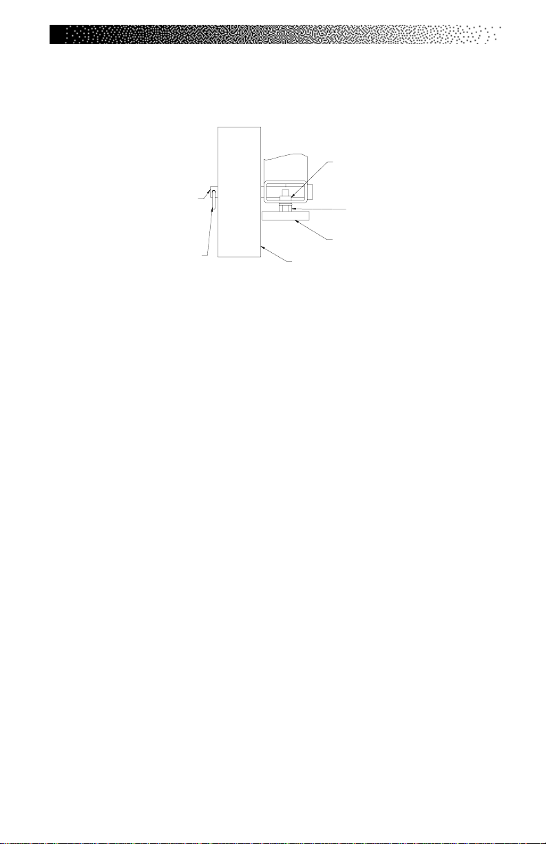
3. Remove the clevis pin from each wheel (See Drawing Below) and remove
the wheels from the frame.
Rivnut
4 X 21767
Clevis Pin
2 X 24439
Cotter Pin
2 X 20047
4. Help your assistant lower the machine to the floor. Install and adjust the
leg levelers as necessary to level the machine (see Above).
5. If your machine was shipped outside North America, it will need additional
assembly (if this is not the case, skip to step #6).
• Use the fastener removal tool to remove the 8 fasteners on the back
panel.
• Mount both handrails onto the frame as shown in Figure 6.
• Push the console cable assembly through the grommet in the frame
and connect it to the main cable assembly (refer to Figure 6).
• Install the console mount onto the handrails (refer to Figure 6).
• Install the console and connect the console cable.
• Reinstall the back panel and go to step #6.
Outside of Machine
Nut
4 X 22154
Leg Levele r
4 X 20017
Transport Wheel
2 x 20036
6. Unwrap the power supply assembly from the console and connect the DC
power cable from the power supply to the power connector located on the
bottom cover.
7. Place the power supply on the floor near an AC wall outlet. To reduce the
hazard of electrical shock, place the power supply in a location away from
the machine and away from exposure to perspiration. You should not
place your power supply on a carpet because it may overheat.
8. Check to be sure that the input AC power rating marked on the power
supply matches the available power. If it does not, obtain the matching
power supply from StairMaster® Health & Fitness Products, Inc. before
proceeding any further.
Page 4
Page 12
INSTALLATION INSTRUCTIONS
WARNING
!
TO REDUCE THE RISK OF ELECTRICAL SHOCK AND FIRE AND TO PREVENT SEVERE
DAMAGE TO THE MACHINE, USE ONLY THE POWER SUPPLY APPROVED FOR USE
WITH THIS EQUIPMENT. IN ADDITION, YOUR MACHINE MUST BE
PROPERLY GROUNDED.
9. Connect the AC power cord to the AC wall outlet. Refer to the “Grounding
Instructions” section of the Manual if the AC wall outlet does not
accept a three-prong plug.
10. Watch the console. The console should display a software revision code and
then show “SELECT WORKOUT.” If it does not, unplug the power supply and
then plug it back in. If the sound and/or the display are still not present,
contact the Customer Service Department at 800-331-3578. International
customers should call their local distributor; refer to the Appendix for the
phone number of the office nearest you.
11. When the console displays “SELECT WORKOUT”, your Stepmill
7000 PT exercise system is ready to use.
12. Custom-length DC cables and other accessories are available. Refer to the
Appendix for the phone number of the office nearest you.
®
Page 5
Page 13
BASIC OPERATING INSTRUCTIONS
GENERAL GUIDELINES FOR SAFE OPERATION
WARNING
!
THESE GUIDELINES ARE DIRECTED TO YOU, AS THE OWNER OF THE
MACHINE. YOU SHOULD INSIST THAT ALL USERS FOLLOW THE SAME GUIDELINES.
YOU SHOULD MAKE THIS MANUAL AV AILABLE TO ALL USERS.
1. Obtain a complete physical examination from your medical doctor and
enlist a health/fitness professional’s aid in developing an exercise
program suitable for your current health status.
2. When working out for the first time, use the MANUAL exercise program at
the lower speeds until you feel comfortable and capable of faster speeds.
3. The speed and duration of your exercise program should always be
subject to how you feel. Never permit peer pressure to exceed your
personal judgment while exercising.
4. Overweight or severely deconditioned individuals should be particularly
cautious when using the machine for the first time. Even though such
individuals may not have histories of serious physical problems, they may
perceive the exercise to be far less intense than it really is, resulting in the
possibility of overexertion or injury.
5. Although all equipment manufactured by StairMaster Health & Fitness
Products, Inc. has been thoroughly inspected by the manufacturing facility
prior to shipment, proper installation and regular maintenance are
required to ensure safety. Maintenance is the sole responsibility of the
owner.
Page 6
Page 14
BASIC OPERATING INSTRUCTIONS
YOUR FIRST WORKOUT ON THE STAIRMASTER® STEPMILL® 7000 PT
EXERCISE SYSTEM
Basic Instructions for First-Time Users
1. Warm up with light calisthenics and easy stretching exercises for at least
five minutes before beginning your exercise program.
WARNING
!
IF A T ANY TIME DURING YOUR WORKOUT YOU FEEL CHEST PAIN,
EXPERIENCE SEVERE MUSCULAR DISCOMFORT, FEEL FAINT, OR ARE SHORT OF
BREA TH, STOP EXERCISING IMMEDIATELY. IF THE CONDITION PERSISTS, YOU
SHOULD CONSUL T YOUR MEDICAL DOCTOR IMMEDIATELY.
2. Hold onto the handrails and step up onto the staircase. Stand up straight.
The steps will rotate slowly.
3. Select the MANUAL exercise program so you can control the pace of your
first workout and get used to the exercise motion.
4. Press [MANUAL] and then [ENTER]. The console will return to the start
screen if you do not press [ENTER] within ten seconds.
5. The console will prompt you to enter your body weight. Enter your weight
in pounds (or kilograms if the console is set up for metric units). Correct
entry errors by pressing [CLEAR] before you press [ENTER].
6. The console will prompt you to enter the workout time in one-minute
increments between five and 99 minutes. Press [1], [0], [ENTER] to exercise
for ten minutes.
7. Step up with one foot at a time. Try to stay towards the top of the
staircase. As you become comfortable with exercise motion, press
[LEVEL: ∧] and [LEVEL: ∨] to adjust your climbing speed.
Page 7
Page 15

BASIC OPERATING INSTRUCTIONS
8. Relax as much as possible while exercising and maintain an erect posture.
Use the handrails for balance. Don’t lock your elbows or lean on the
console. Supporting your weight will reduce the exercise intensity and the
console will overestimate the number of calories burned.
9. Select a speed (or intensity level) that allows you to step towards the top
of the staircase. Faster is not always better. Exercise at a level that is
consistent with your fitness level.
Rest Periods
10. You can stop and rest as many times as necessary for up to one
minute for each rest period during all programs. To stop, either press
[STOP] or step off the machine. The console returns to the start screen if
you rest longer than the allotted rest period. Follow the onscreen
prompt to continue your work out after a rest period.
Cool Down
11. When you are finished with your workout, the machine will slow
down and the message “GOAL A TTAINED” will be displayed. You can
cool down on the machine by continuing to step. The console timer
will continue to count up from the selected time, and the intensity
level will default to level 3. If there is a time limit set on the console,
the timer will last only until the maximum time has been met. For
example, if the time limit was set for 30 minutes and you worked out
for 25 minutes, the cool down period would last for 5 minutes, or until
you stepped off the machine.
12. You can also cool down by getting off the machine walking or
stretching for at least five minutes.
Page 8
Page 16
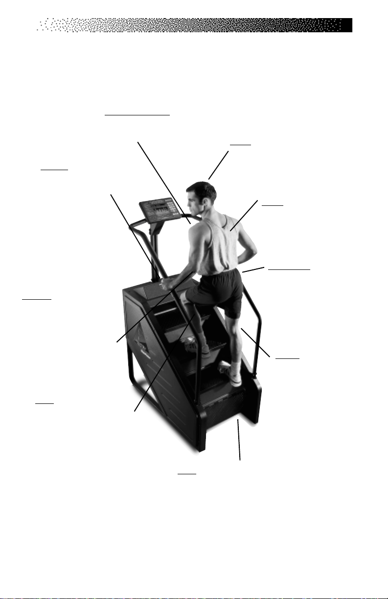
Chest/Shoulders - Keep your
shoulders square and centered
over your hips with your chest
lifted.
Hands - Rest your
hands lightly on the
side rails or front
handlebars.
Excessive leaning on
the side rails can
reduce calorie burn
by up to 20%.
Elbows - Keep both elbows
slightly bent. If you have
good balance and want to
burn more calories, you can
pump your arms back and
forth as if you were running.
Legs - Use a full, pain-free
range of motion with each
step, straightening your legs as
far as possible without causing
discomfort or letting your
knees lock out.
BASIC OPERATING INSTRUCTIONS
Figure 1: Correct Exercise Position
Head - Keep your chin parallel to the
floor . Avoid staring at your feet or the
computer console. This posture will also
enhance your breathing.*
Back - Although the whole
body is in a slightly forward
slant, keep your back straight
and avoid bending at the waist.
Hips/Torso - Keep your hips
directly under you with the
buttocks slightly contracted.
Avoid letting your hips rock
from side to side with each
step.
Knees - Keep your knees
aligned with your toes.
Avoid training with your
knees too far past your
toes and keep your feet
pointing forward. Do not
hyperextend your knees.
Feet - Step squarely in the middle of
each step.
*Please note that in the photo the person has his head turned - keep your head
facing forward as you exercise.
Page 9
Page 17

HEART RATE MONITORING
HEART RA TE INPUT
The 7000 PT console uses telemetry (e.g., Polar®) heart rate signal detection.
Ensure that your console is set up for telemetry signal detection only. There is a
short “lock out” period at the beginning of each workout session during which
the console first detects a signal and then validates the signal type.
• Telemetry heart rate - after the initial belt signal is detected, the
console will enter a validation phase in which four good heart
beat signals within four seconds are required before
locking on telemetry heart rate signals for the duration of the
workout session. During the validation phase the console will not
recognize contact heart rate signals.
Locked/Non-locked Option
When the “not locked” option is selected the heart rate source signal is not fixed
during the exercise (if the signal is lost either input will be valid). If the “locked”
option is selected then the heart rate source signal is locked on the first detected
signal during the workout. To set a heart rate signal input, or to turn off the heart
rate option all together, perform the following steps:
Page 10
1. On the console keypad, press [LEVEL: ∧], [3], [2]. At this point the
screen will display “HR INPUTS.” Press [ENTER] to select this
option.
2. There are 4 options to handle heart rate input signals. Only 2 of
those options are appropriate for the 7000 PT; "Both HR Off", and
"Telemetry Only." Press the [SELECT] key to scroll past the other
options until you find either "Both HR Off" or "Telemetry Only."
Press the [ENTER] key to select the desired option.
Page 18

HEART RATE MONITORING
“TELEMETRY ONLY“ - locks out contact heart rate signals
and will only detect telemetry signals. Set your console to this
default.
“BOTH HR OFF“ - turns off the ability to detect any signal at all.
Used in rare situations where there is excessive interference with
the heart rate signals. This option turns off disables the
Constant HR program and the Fitness Test program.
Error Messages
Text line messages are only seen in the Constant Heart Rate and Fitness Test
programs due to the design of the program that necessitates a valid heart rate
signal at all times during the program.
“
CHECK HR BELT
the last 30 seconds in telemetry signal detection.
“HR BELT NEEDED” - No telemetry belt signal been sensed
during the initial setup time.
“HR MODE DISABLED” - No heart rate signal is allowed due to
the set up option that was chosen. Heart rate monitoring is not
possible.
” -
The heart rate signal has been missing for
Page 11
Page 19
TELEMETRY HEART RATE
TELEMETRY HEART RATE
The StairMaster® Stepmill® 7000 PT features telemetry (Polar®) heart rate monitoring. The system consists of the receiver, located on the stepper, and a transmitter belt (purchased separately) worn across your chest. The monitoring function is activated as soon as you strap on the chest belt and step within range of
the receiver in the machine. Two electrodes on the underside of the chest belt
sense the heart rate signal and send it to the receiver. The heart symbol on the
console pulses to indicate that the console is receiving a valid signal. A microprocessor in the console calculates the heart rate and displays it, in beats per
minute, on the console.
Using the Transmitter Belt
WARNING
!
PACEMAKER USERS SHOULD NOT USE THE POLAR
TRANSMITTER BEFORE CONSULTING THEIR DOCTOR.
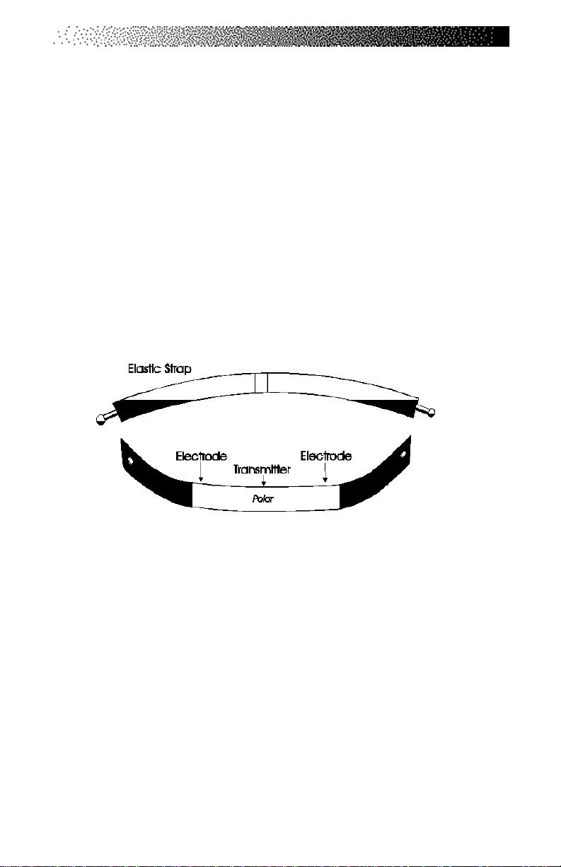
Before you put the transmitter belt on, wet the two electrode patches
(the grooved rectangles on the reverse side of the belt). Secure the transmitter
belt as high under the pectoral muscles (chest) as is comfortable. The transmitter
belt should fit snugly and comfortably, and allow normal breathing. When the
console detects a heart rate signal, heart rate is shown in the display automatically. Your heart rate in beats per minute and a pulsing heart icon are displayed
on the console.
After the initial belt signal is detected, the console will enter a validation phase in which four good heart beat signals lasting four seconds each are
required before locking on telemetry heart rate signals for the duration of the
workout session. During the validation phase the console will not recognize
contact heart rate signals. If you do not see a heart rate on the console, try one
of the following:
• Move closer to the console.
Page 12
Page 20
TELEMETRY HEART RATE
• Tighten the elastic part of the chest belt.
• Adjust the belt higher or lower on your chest.
• Remoisten the electrodes.
• Test your chest strap with a machine that you know is working, or
with a heart rate watch that you know is working.
• If possible, replace or exchange your console with a console
(from the same type of machine) that you know is working and
retest the machine.
• Visually check that the heart rate receiver is positioned correctly
in the neck cover. The heart rate receiver jack should point down.
Ensure that the heart rate receiver is connected to the console,
and that the connection is not loose. If possible, swap the heart
rate receiver with one from another machine.
Figure 2: Transmitter Belt
Maintaining the Transmitter Belt
Clean the chest belt regularly with mild soap and water, then dry thoroughly residual sweat and moisture keep the transmitter active and drain the battery in
the transmitter. Do not use abrasives or chemicals such as steel wool or alcohol
for cleaning, as they can damage the electrodes permanently. You can order
replacement belts from StairMaster, Polar Electro, Inc., or your local fitness store:
StairMaster 800-331-3578 P/N 64000
Polar Electro, Inc. 800-227-1314
Page 13
Page 21
7000 PT CONSOLE
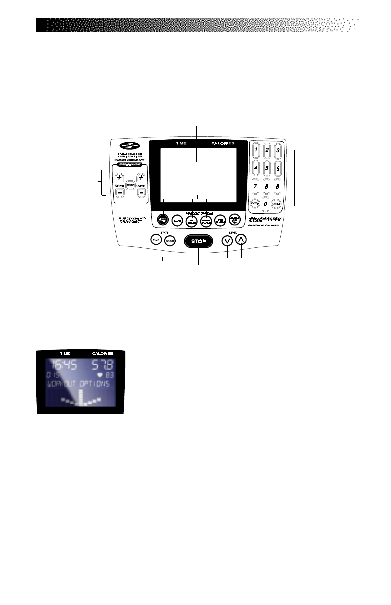
The StairMaster® Stepmill® 7000 PT exercise system console is divided into
seven sections: the display window, the workout options, the numeric keypad,
the entertainment keypad, the workout statistics, the stop key, and the intensity
level keys (see Figure 3).
Display Window
Entertainment
Keypad
Workout Statistics
Figure 3: The Stepmill 7000 PT Console
THE DISPLAY WINDOW
• Calories
displayed in the upper right section of the display window.
• Interval Timer
timer counts down time left within each interval.
• Heart Rate
heart icon.
- The real-time amount of calories burned is continually updated and
- The interval timer is displayed below the Time. The interval
- Current heart rate is displayed below the Calories, next to the
• Workout Option Profile
in the lower section of the display window during a workout. The taller the column, the higher the intensity (watts) for that interval. The flashing column shows
your current interval. The flashing column moves from left to right across the display as you complete each interval.
Workout Options
Stop
• Time
upper left section of the display window. Once the time
is entered, the timer will count down, in minutes and
seconds, until the workout is finished or stopped. If [0]
is entered in the MANUAL or CONSTANT HEART RATE
program, the timer will count up.
- The selected workout time is displayed in the
- A profile of the selected exercise program appears
Intensity Level
Numeric
Keypad
Page 14
Page 22
THE NUMERIC KEYPAD
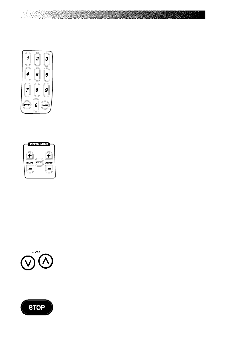
The numeric keypad is located on the right side of the console.
Before the exercise program begins, the numbers are used to
enter data in response to the console prompts.
• Enter
tion used by the console to calculate workout statistics.
• Clear
pressed before [ENTER].
THE ENTERT AINMENT KEYPAD
• Volume Up/Down
source.
• Mute
- Removes the audio sound from the headphones.
• Channel Up/Down
system.
- Confirms workout selections and stores the informa-
- Erases information from the console memory if
The FreeClimber comes equipped to facilitate the use of commercial entertainment systems. Using any of these keys will
send an output signal through the Communication Specification for Fitness Equipment (C.S.A.F.E.) port to a connected
C.S.A.F.E. or compatible system. If a system is not connected,
pressing these keys will have no effect.
- Increases or decreases the volume level of the audio
- Changes the channel of the commercial entertainment
7000 PT CONSOLE
THE INTENSITY LEVEL KEYS
The exercise intensity level may be changed at any time during
a workout. Pressing the [
pressing the [ ∧ ] key increases the intensity.
STOP KEY
Press the [STOP] key any time you want to pause the exercise
program for up to one minute. Press [STOP] a second time, or
[1], and The console will return to the "SELECT WORKOUT"
∨ ] key decreases the intensity and
Prompt.
Page 15
Page 23

7000 PT CONSOLE
THE WORKOUT STATISTICS
During the exercise program, the Stats keys are used to track workout statistics
which are then shown in the display window. Pressing the [SELECT] key turns off
the scanning feature and shows the statistic of choice in the display window.
Pressing the [SCAN] key will prompt the console to cycle through the following
statistics:
Distance
•
kilometers), you would have traveled while riding a bicycle outdoors at the same
relative intensity.
•
Calories/Hour
ing a workout.
•
Rate -
•
Floors
There are 16 steps per floor, and 48 floors per mile.
•
Level
hardest).
•
Watts
•
METs
tiples of the resting metabolic rate. While you are sitting quietly, your body consumes oxygen at the rate of about 3.5 milliliters per kilogram of body mass per
minute. When you exercise, your body needs more oxygen in order to function.
For example, exercising at 10 METs requires ten times the resting rate of oxygen
consumption, or about 35 milliliters per kilogram per minute. During a workout,
this key shows the current MET level. During the workout summary, the average
MET level is displayed.
•
Target Heart Rate
Shows the selected target heart rate.
- Provides a cumulative total of the equivalent distance (in miles or
- Provides a running total of the number of calories burned dur-
Displays the current steps per minute.
- Displays the equivalent number of floors climbed with an 8-inch step.
- Shows the current intensity level between 1 (the easiest) and 20 (the
- Displays the exercise intensity in watts (746 watts = 1 horsepower).
- Gives you the relative energy cost of exercise. MET stands for mul-
- Available only during the Constant Heart Rate program.
At the completion of a workout, the statistic averages are calculated
based on the accumulation of data during the workout program, and not including
the cool down period.
Page 16
Page 24

7000 PT CONSOLE
THE EXERCISE PROGRAM KEYPAD
The exercise keypad is located below the display and to the left of the function
keypad. While the console is in the “SELECT WORKOUT” mode, press one of the
exercise program keys to preview the desired workout. There are six
workout programs with the following standard defaults (pressing [ENTER] without inputting data first will prompt the console to enter these values):
• Weight - 175 lbs.
• Intensity Level - 3
• Workout Time - The default time in the programmed workouts
and Quick Start is 20 minutes. The Manual and Constant Heart
Rate programs do not have a specified default time. In these
programs, the console timer will count up to the maximum time of
99 minutes, and then return to 0.
• Age (Constant Heart Rate program only) - 40 years
Once you have selected a program, the prompts are:
•“ENTER BODY WEIGHT” - type in your body weight in
pounds (or kilograms if your console is set to metric units).
•“ENTER LEVEL 1 - 20” - select your intensity level with
level 1 being the easiest and level 20 the hardest.
•“ENTER TIME 5 - 99” - select the workout duration in one
minute increments from 5 to 99. Press 0 in the MANUAL and
CONSTANT HEART RATE program to workout for an unspecified
amount of time.
The Quick Start Program
Provides an immediate start, without having to enter any user information. This
program uses the standard default settings for derivation of calories burned.
The Manual Program
After pressing the [MANUAL] key, enter user and workout information. Begin
exercising at the selected level. If desired, adjust the workout manually by
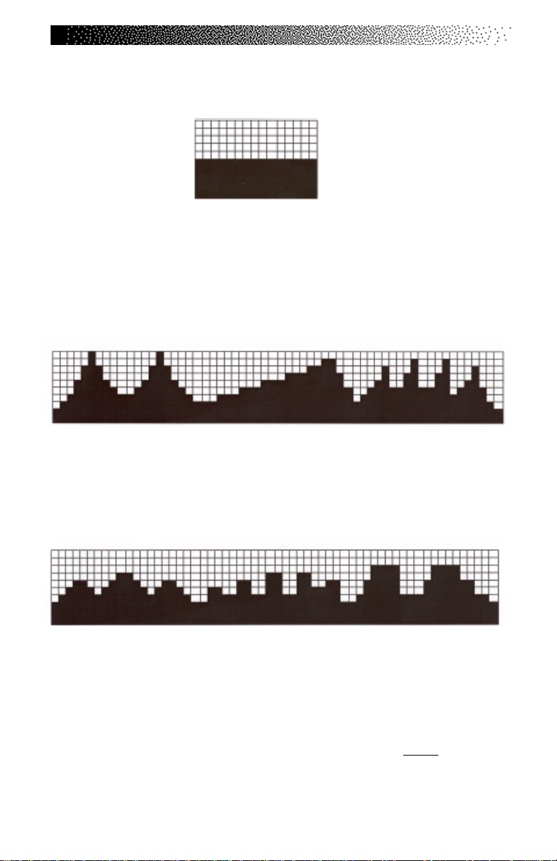
using the intensity level arrow keys. The profile in the display window is
divided into 15 equal intervals within the workout time. The profile is based
Page 17
Page 25
7000 PT CONSOLE
on the selected intensity level, with 2 levels equating to one vertical bar.
The Fat Burner Program
The Fat Burner program is a 60-interval workout designed for people just
starting a weight control program. The relative intensity level is indicated on the
profile and any changes in the intensity level will continue for the remainder of
the program.
The Aerobic Training Program
The Aerobic Training program is a 60-interval workout designed to increase
aerobic capacity. The relative intensity level is indicated on the profile and any
changes in the intensity level will not change the look of the remaining profile.
The Speed Intervals Program
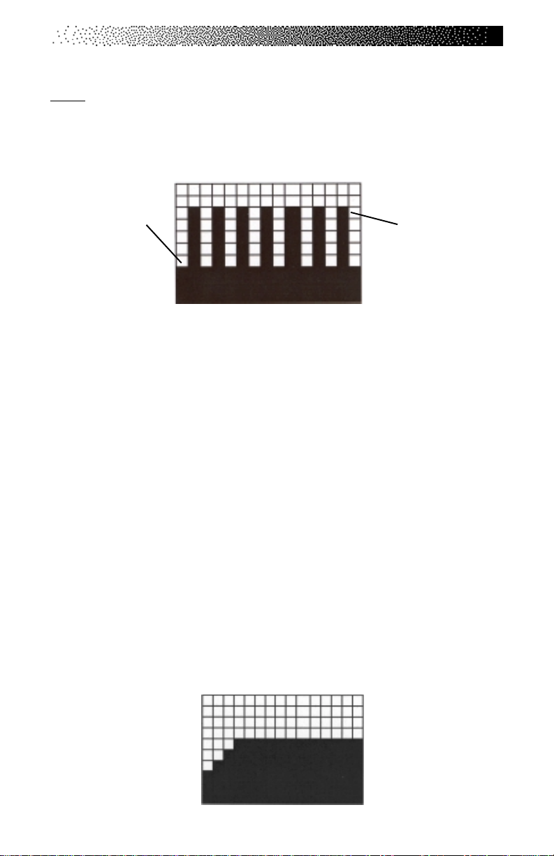
The Speed Intervals program is a workout with 8-rest intervals and 7-exercise
intervals that alternate speed/intensity level changes. You can change the REST
interval speed/level and the EXERCISE interval speed/level independently, using
the level keys. For example, if you decrease the intensity level during a rest interval then subsequent rest intervals will be the same. However, the EXERCISE
interval remains at the same intensity level you started with. To change the
intensity level of the EXERCISE interval, you must change the intensity level
Page 18
Page 26
7000 PT CONSOLE
during an EXERCISE interval. The intensity level shown during an EXERCISE interval is indicative of your current speed. However, the current speed during a REST
interval is equal to a scaled percentage of the displayed intensity level. Note that
the program profile does not change at any time during the workout session.
Rest Interval
The Constant Heart Rate Program
The Constant Heart Rate program maintains a chosen target heart rate by
automatically varying the climbing speed during each workout. The default target
heart rate is equal to 70% of your maximum heart rate which is calculated by the
following equation: 220 - (Age) x .70. Choose a different target heart rate (between 80 and 180 beats per minute) at any time during the workout by using the
numeric keypad to enter the new target heart rate, followed by the [ENTER] key.
The following messages may be shown during a workout:
•“CHECK HR BELT
the last 30 seconds in telemetry signal detection.
•“HR BELT NEEDED” - No telemetry belt signal has been sensed
during the initial setup time.
• “HOLD HR SENSORS” - In contact heart rate signal situations
this message will come every 30 seconds to prompt the user to
hold the sensors.
•“HR MODE DISABLED” - No heart rate signal is allowed due to
the set up option that was chosen. Heart rate monitoring is not
possible.
” -
The heart rate signal has been missing for
Exercise Interval
Page 19
Page 27

7000 PT CONSOLE
The Fitness Test Programs
Understanding Submaximal Exercise Testing
Before using the StairMaster FreeClimber for submaximal exercise testing, it
should be noted that all submaximal fitness tests make several assumptions:
• That a steady-state heart rate is obtained for each exercise
workload.
• That a linear relationship exists between heart rate, oxygen up
take and workload.
• That the maximal heart rate for a given age is uniform.
• That the mechanical efficiency of the physical activity performed
(i.e., oxygen uptake at a given workload) is the same for every
one.
It should be kept in mind that any one or all of the above mentioned assumptions may not be met during a submaximal exercise test. If for any
reason one of the assumptions is not met, then errors in predicting VO
occur.
2 max
will
Unfortunately, it is often quite difficult to meet all of the requirements
for the four listed assumptions. For example, exercising at a given workload for
only a few minutes can involve an insufficient amount of time for many individuals to achieve a true steady-state. To ensure that a steady-state has been
achieved, the heart rate should be measured after two minutes of exercise at a
given workload and again after the third minute of exercise at that workload.
These two heart rates should then be compared. If a difference of more than five
beats per minute between the two is found, the subject should continue to exercise at one-minute intervals at the same workload until two successive heart
rates differ by less than five beats per minute.
It is also important that the submaximal heart rates obtained be
between 115 and 150 beats per minute, because it is within this heart rate range
that a linear relationship tends to exist between heart rate and oxygen uptake or
workload for most adults. When the heart rate is less than 115, many external
factors (e.g., talking, laughing, apprehension, etc.) can greatly influence heart
rate. Once the heart rate reaches a level between 115 and
Page 20
Page 28

7000 PT CONSOLE
150, external factors no longer influence heart rate, and a linear relationship exists. As the heart rate rises above 150, the heart rate-oxygen uptake relationship
becomes curvilinear .
The third assumption involves maximal heart rate. Maximal heart rate is
the greatest heart rate that can be measured when an individual is exercising to
the point of volitional fatigue (i.e., exhaustion) during a graded exercise test. Several equations have been developed to estimate the average maximal heart rate
for humans:
• Maximal heart rate = 220 minus age (low estimate)
• Maximal heart rate = 210 minus [0.5 x age] (high estimate)
• Maximal heart rate = 226 minus age (estimate for older
individuals)
Maximal heart rate can, however, vary greatly among different
individuals of the same age. One standard deviation is + 12 bpm, which means
that two-thirds of the population varies an average of plus or minus 12 heart
beats from the average given by a prediction equation. If an individual’s age-pre-
dicted maximal heart rate is higher than that person’s true maximal heart rate,
then his/her estimated VO
value.
will be an overestimation of the correct or actual
2 max
The final assumption addresses the issue of mechanical efficiency. Because oxygen uptake at any given work rate can vary by approximately 15% between different individuals, individuals vary in the amount of oxygen they require
to perform a certain exercise workload. Some individuals are more
efficient at performing a given task than others. As a result, the average
oxygen consumption associated with a given workload may vary significantly
from one person to another. Thus, VO
predicted by submaximal exercise tests
2 max
tends to be overestimated for those who are mechanically efficient and underestimated for those who are inefficient.
The point to remember is that submaximal exercise testing, though not
as precise as maximal exercise testing, is not without advantages. For
example, the results of such testing can provide a fairly accurate reflection of an
individual’s fitness status without the cost, risk, effort (on the part of the subject)
and time involved in max testing. If an individual is given repeated
Page 21
Page 29

7000 PT CONSOLE
submaximal exercise tests and that person’s heart rate response to a fixed
workload is found to decrease over time, it is reasonably safe to conclude that
the individual has made improvements in aerobic (cardiorespiratory) fitness, irrespective of the accuracy of the VO
Pretest Screening
Prior to any exercise test (maximal or submaximal), participants should complete
a brief health/medical questionnaire, have their resting blood pressure and heart
rate measured, and provide an informed consent form. The Physical Activity
Readiness Questionnaire (PAR-Q) is an example of a valid health/medical
questionnaire for screening individuals prior to submaximal exercise testing.
Canadian health and fitness practitioners have extensively (and quite successfully) used the PAR-Q to determine whether individuals should be given an
exercise test. A “yes” answer to any of the seven questions on the PAR-Q would
disqualify a participant from taking part in an exercise test until appropriate
medical clearance was obtained.
PHYSICAL ACTIVITY READINESS QUESTIONNAIRE (PAR-Q)
1. Has your doctor ever said you have a heart condition and recommended
only medically supervised physical activity?
2. Do you have chest pain brought on by physical activity?
3. Have you developed chest pain within the past month?
4. Do you tend to lose consciousness or fall over as a result of dizziness?
5. Do you have a bone or joint problem that could be aggravated by the
proposed physical activity?
6. Has a doctor ever recommended medication for your blood pressure or a
heart condition?
7. Are you aware, through your own experience or a doctor’s advice, of any
other physical reason against your exercising without medical supervision?
prediction.
2 max
The StairMaster Submaximal Fit Test
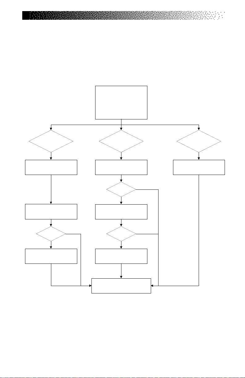
The StairMaster branching protocol is a series of 3-minute stages of
continuous exercise at increasing intensity. The first stage is a warm-up at approximately 4 METs. The intensity of the remaining stages is based on the heart
rate response to the warm-up. The test is designed to raise the steady
Page 22
Page 30

7000 PT CONSOLE
state heart rate of the subject to 110 to 150 beats/min for two consecutive
stages. It is important to remember that two consecutive heart rate measurements must be obtained in the 110 to 150 beats/min range to predict VO
The test typically lasts from 9 to 15 minutes.
In the StairMaster protocol, each work rate is performed for 3
minutes, with heart rates recorded during the final 4 seconds of the second and
third minutes of each stage. If the heart rates are within 5 beats/min, then the
heart rate during the last minute is plotted against the work rate, and the program advances to the next 3-minute stage. The program continues for two to four
stages until two steady state heart rates between 110 to 150 beats/min are obtained in two consecutive stages. The line generated from the plotted points is
then extended to the age-predicted maximal heart rate. A corresponding maximal
work rate and VO
can then be calculated.
2max
At the end of the 3rd minute of each stage, if the heart rates at the end
of the 2nd and 3rd minute are not within 5 beats/min of each other, then that work
rate is maintained for an additional minute. At the end of the 4th minute, the
heart rate is compared to the heart rate at the end of the 3rd minute. If the heart
rates are within 5 beats/min, then the heart rate during the 4th minute is plotted
against the work rate. If the heart rate at the end of the 3rd and 4th minute are
not within 5 beats/min, then the work rate is maintained for one more additional
minute. If the heart rate at the end of the 4th and 5th minutes are within 5 beats/
min, then the heart rate at the end of the 5th minute is plotted against the work
rate. If the heart rate at the end of the 4th and 5th minutes are not within 5 beats/
min, then the test failed.
2max
.
Once two consecutive heart rate measurements are obtained in the 110
to 150 beats/min range, then the test ends successfully and the results are displayed. Estimate maximum aerobic capacity is shown in ml/kg/min and METs.
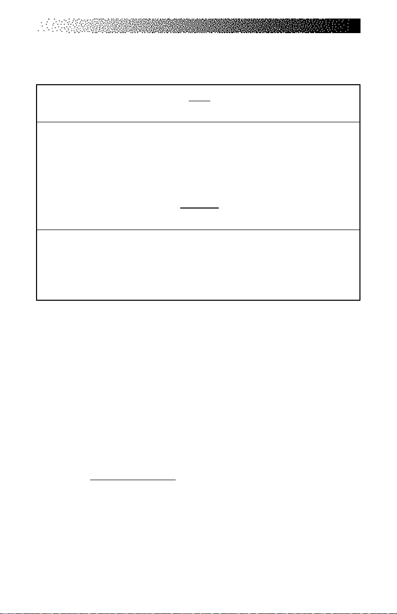
Next, the results are compared to normative values for others of the same age
range and gender (see Table 2). Results are stored in the console until the next
person starts an exercise program. Press [STATS SCAN] to review the results in
addition to being displayed at the end of the test.
Page 23
Page 31
7000 PT CONSOLE
Figure 4: StairMaster® Fitness Protocol
FIT TEST PROTOCOL
StairMaster CV Products
First Work Level
4 METs
If 100 <= HR <= 120If HR < 100 If HR > 120
Second Wor k Level
7 METs
Third Work Level
9 METs
Fourth Work Level
11 METs
Second Wor k Level
6 METs
If HRs >115
Third Work Level
8 METs
If HRs >115If HRs >115
Fourth Work Level
10 METs
Test Complete
- Display Results -
Second Wor k Level
5 METs
Y
YY
Test fails if 2 stages of
at least 115 bpm are not
obtained
Page 24
Page 32
7000 PT CONSOLE
Table 2. Fitness Rating Norms (VO
MEN
Age High Good Average Fair Low
20 – 29 >51 51 – 47 47 – 43 42 – 40 <39
30 – 39 >50 50 – 45 45 – 41 41 – 37 <37
40 – 49 >48 48 – 42 42 – 38 38 – 35 <35
50 – 59 >45 45 – 39 38 – 35 35 – 32 <32
60+ >43 42 – 35 35 – 32 32 – 29 <29
WOMEN
Age High Good Average Fair Low
20 – 29 >44 44 – 38 38 – 35 35 – 32 <32
30 – 39 >41 41 – 37 37 – 34 34 – 31 <30
40 – 49 >40 39 – 34 34 – 31 31 – 28 <28
50 – 59 >35 35 – 31 31 – 28 28 – 26 <25
60+ >35 35 – 39 29 – 26 26 – 24 <24
The Firefighter’s Stair Climb Tests
The StairMaster StepMill is routinely used to assess the aerobic fitness
levels of fire fighters in full protective gear carrying heavy equipment. The
Candidate’s Physical Ability Test (CPAT), approved by the International
Association of Fire Fighters (IAFF) and reviewed by the U.S. Justice Department,
requires each candidate to step on the StepMill at a predetermined stepping
pace for a specific period of time. There are two fire fighter specific Stair Climb
Test programs. The first test is the CPAT Stair Climb Test. The second test is a
modified version of the CPAT test that is used by the New York City Fire Department (NYCFD).
2max
)
•
CPAT Stair Climb Test – (Fit Test #2) The first phase is a warm-up
interval at intensity of 56 steps/min and lasts twenty-seconds. At
the end of the first interval the time counter will reset to zero.
The second phase continues through nine twenty-second
Page 25
Page 33

7000 PT CONSOLE
intervals at intensity of 68 steps/min. The CPAT Stair Climb Test
has a total of ten intervals and lasts for three minutes, twenty
seconds (including warm-up).
Turning on the CPAT Stair Climb Test
1. Press [∧], [9], [1], [ENTER], on the console keypad. Make sure to
press in the middle of each key and be aware that the corresponding numbers will not show in the console display.
2. The console will prompt you to “BEGIN FIT TEST.” The test
can be stopped at any time by pressing [STOP].
• NYCFD Stair Climb Test – (Fit Test #3) The first phase is a warm-
up interval at intensity of 56 steps/min and lasts sixty-seconds,
followed by a sixty-second rest period (no stepping). At the end
of the rest period the time counter will reset to zero. The second
phase is at intensity of 68 steps/min and lasts for five minutes,
twelve seconds.
Turning on the NYCFD Stair Climb Test
Page 26
1. Press [∧], [9], [2], [ENTER], on the console keypad. Make sure to
press in the middle of each key and be aware that the corresponding numbers will not show in the console display.
2. The console will prompt you to “BEGIN FIT TEST.” The test
can be stopped at any time by pressing [STOP].
Page 34

7000 PT CONSOLE
CONSOLE CODES
There are three groups of console codes which are differentiated according to
function. The first group of codes are customization codes and are used to set
defaults such as units, language, heart rate input type, etc. The second group of
codes are machine status codes and are used to track hours and other general
usage patterns for maintenance purposes. The third group of codes are diagnostic codes and are used for troubleshooting. The following key actions are valid in
each group of console codes:
• Pressing [LEVEL ∧], [ 1st # ], [ENTER] displays what group of codes is
being accessed.
• Pressing [SELECT] or [LEVEL ∧] at that point allows you to view all
possible selections. Once in this mode pressing [LEVEL ∨] backs up
through the selections; pressing [ENTER] then selects that item. If
another test level is available at this point, the [SELECT] / [ENTER]
process is repeated.
• Pressing [∧] [1st #, or 2nd #], [ENTER ] selects that item directly.
• Pressing [CLEAR] exits any of the special access modes.
Custom Codes
[ ^ ] [ 3 ] [ 0 ] change workout time limit between 5 to 99 minutes
[ ^ ] [ 3] [ 1 ] change units (MPH or KMH)
[ ^ ] [ 3 ] [ 2 ] choose type of heart rate input and priority (telemetry
or contact)
[ ^ ] [ 3 ] [ 3 ] - N/A [ ^ ] [ 3 ] [ 4 ] choose console language
[ ^ ] [ 3 ] [ 5 ] change contrast on console
[ ^ ] [ 3 ] [ 6 ] - N/A [ ^ ] [ 3 ] [ 7 ] - N/A [ ^ ] [ 3 ] [ 8 ]
[ ^ ] [ 3 ] [ 9 ] reset to factory defaults
1. Change the workout time by pressing [LEVEL: ^], [3 , [0]. The console will
display “MAX TIME.” Press [ENTER]. The console will then display the
current time limit. Use the keypad to enter the desired time, then press
[ENTER]. For no time limit, press [0].
-
N/A
-
Page 27
Page 35

7000 PT CONSOLE
2. Change the units to either Metric or USA units by pressing [LEVEL: ^], [3],
[1], [ENTER]. The console will display the current units - either “USA
UNITS” or “METRIC UNITS.” Use the [SELECT] key to change option, and
then press [ENTER].
3. Choose the desired heart rate input preference by pressing [LEVEL: ^],
[3], [2]. The console will then display “HR INPUTS.” Press [ENTER]. The
console will then display the current hear rate input selection. Press the
[SELECT] key to scroll through the other options. Press [ENTER] after the
desired option.
4. Change the language by pressing [LEVEL: ^], [3], [4]. The console will
display “LANGUAGE.” Press [ENTER]. The console will then display
the current language. Press the [SELECT] key to scroll through the other
options. Press [ENTER] to change the option.
5. Adjust the contrast on the LCD screen by pressing [LEVEL: ^], [3], [5]. The
console will display “CONTRAST ADJ.” Press [ENTER]. The console will
then display the current contrast number. Press the [LEVEL: ^], and
[LEVEL: ∨] keys to increase or decrease the contrast. The changed value
will remain on exit.
6. Reset the console to factory defaults by pressing [LEVEL: ^], [3], [9]. The
console will display “SET DEFAULTS .“ Press [ENTER]. Then console will
rest itself and then display “DONE.”
Quick Scan Programming
You can quickly access any of the custom menus by pressing [LEVEL: ^],
[3], [ENTER]. The console will then display “CUSTOMIZE.” Scroll through the
following options:
[SELECT]“ MAX TIME
[SELECT]“CHANGE UNITS” 1
[SELECT]“HR INPUTS” 2
[SELECT]“LANGUAGE” 4
[SELECT]“CONTRAST ADJ” 5
”
0
Page 28
Page 36

7000 PT CONSOLE
[SELECT]“CONTRAST ADJ” 5
[SELECT]“MAX SPEED” - N/A- 6
[SELECT]“CLINICAL MODE”-N/A-7
[SELECT]“SET DEFAULTS “ 9
Machine Status Codes
[ ^ ] [ 4 ] [ 0 ] display machine run time in hours
[ ^ ] [ 4 ] [ 1 ] display number of workouts
[ ^ ] [ 4 ] [ 2 ] display distance traveled
[ ^ ] [ 4 ] [ 3 ] display software rev
[ ^ ] [ 4 ] [ 4 ] display machine type
[ ^ ] [ 4 ] [ 5 ] -N/A-
[ ^ ] [ 4 ] [ 6 ] display machine run time in hours since last cleared
(used for maintenance)
1. Display the machine run time by pressing [LEVEL: ^], [4], [0]. The console
will display “RUN HOURS XXXXX”.
2. Display the number of workouts by pressing [LEVEL: ^], [4], [1]. The console
will display “WORKOUTS XXXX.”
3. Display the total distance covered up to date by pressing [LEVEL: ^], [4], [2].
The console will then display “DISTANCE XXXX.”
4. Display the console software revision number by pressing [LEVEL: ^], [4],
[3]. The console will display “CONS 92111-XXX.”
5. Display the machine type by pressing [LEVEL: ^], [4], [4]. The console will
display “STEPPER (or other machine type).”
6. Display the machine run time since last cleared by pressing [LEVEL: ^], [4],
[6]. The console will display “MAINT HOURS XXXX.”
Page 29
Page 37

7000 PT CONSOLE
Quick Scan Programming
You can quickly access any of the custom menus by pressing [LEVEL: ^],
[4], [ENTER]. The console will then display “MACHINE STATUS.” Scroll through
the following options:
[ SELECT ] “ RUN HOURS XXXX” 0
[ SELECT ] “ WORKOUTS XXXX” 1
[ SELECT ] “ DISTANCE XXXX” 2
[ SELECT ] “ CONS 90211- XXX ” 3
[ SELECT ] “ STEPMILL” 4
[ SELECT ] -N/A-
[ SELECT ] “ MAINT HOURS xxxx” 6
Resetting the Maintenance Hour Counter
For ease of maintenance records, the Stepmill® console has a maintenance timer
that will clock the number of hours, workouts, and time between last servicing.
After each maintenance period reset the counter.
[ ^ ] [ 7 ] [ 1 ] Reset Service
1. Reset the maintenance hour counter by pressing [LEVEL: ^], [7], [1]. The
console will dusplay “RESET SERVICE.” Press [ENTER]. The console will
display “DONE.” Press [CLEAR] to return to the starting screen.
Configuration Code
The Stepmill console supports other StairMaster® exercise systems. It is
important to verify that the machine configuration code matches the type of
machine you have. Speed control problems, along with other problems, can occur
if the console is not set up correctly.
[ ^ ] [ 8 ] [ 0 ] Change Machine
1. Change the machine type by pressing [LEVEL: ^], [8], [0]. The console will
display “CHANGE MACHINE.” Press [ENTER]. The console will then display
the current machine type. Use the [SELECT] key to toggle between
options. Press [ENTER] for the desired option.
Page 30
Page 38

MAINTENANCE INSTRUCTIONS
HELPFUL HINTS
Read all maintenance instructions thoroughly before beginning work. In some
cases, an assistant is required to perform the necessary tasks. The safety level
given by the design of this equipment can only be maintained when the equipment is regularly examined for damage and wear . Inoperable components shall
be replaced immediately or the equipment shall be put out of use until it is
repaired. All references to the right or left side and to the front or back are made
as if you were on the machine ready to exercise.
TOOL LIST
The following tools are needed to perform service and maintenance:
• Standard screwdriver • Phillips screwdriver
• Combination wrenches (sizes 7/16 - 3/4") • Adjustable wrench
• Combination pliers • External snap ring pliers
• Shop goggles or other eye protection • Wire stripper/crimper tool
• Allen wrench set (sizes 5/64 - 1/4") • Volt-ohm meter (multimeter)
• Socket set or nut driver set • Locking pliers
(sizes 1/4 - 3/4" in 1/16" increments)
MAINTENANCE RECORDS
For ease of maintenance the 4400/4600 PT/CL console will keep track of hours,
number of workouts, time between last servicing, etc. You can quickly access any
of the custom menus by pressing [LEVEL: ^], [4], [ENTER]. The console will then
display “MACHINE ST ATUS”. Scroll through the following options:
[ SELECT ] “ RUN HOURS XXXX”*0
[ SELECT ] “ WORKOUTS XXXX” 1
[ SELECT ] “ DISTANCE XXXX” 2
[ SELECT ] “ CONS 90211- XXX ” 3
[ SELECT ] “ STEPMILL” 4
[ SELECT ] -N/A-
[ SELECT ] “ MAINT HOURS xxxx” 6
*The machine may show a few hours of use due to testing at the
manufacturing facility.
Page 31
Page 39
MAINTENANCE INSTRUCTIONS
INITIAL SERVICE
Upon receiving your machine, use a soft, clean towel to wipe off the dust which
may have accumulated during shipping. Your new machine will require minor
assembly. Refer to the “Installation Instructions” section of this Manual for
details.
PREVENTIVE MAINTENANCE
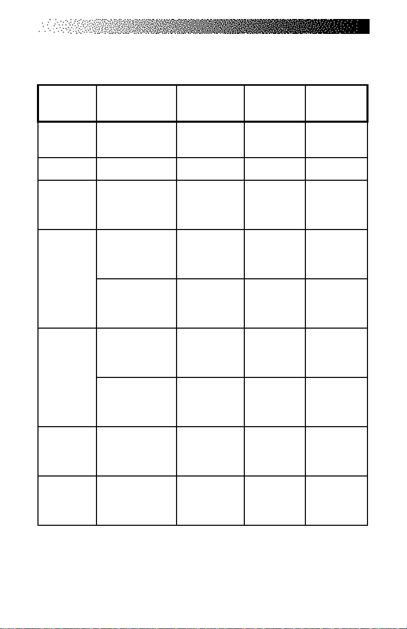
The procedures for performing the recommended preventive maintenance
are summarized in Table 3. The schedule is based on normal usage in a commercial health club environment; adjust the schedule to meet actual machine usage.
Refer to the “Parts Removal and Replacement” section of this Manual for all
disassembly and assembly instructions.
!
TO AVOID INJURY DUE TO SLIPPERY PEDAL SURFACES, DO NOT USE
PETROLEUM-BASED CLEANERS OR ARMORALL-TYPE PROTECTANTS
ANYWHERE ON THIS MACHINE OR THE FLOOR MATS.
Cleaning and Inspecting
1. DO NOT USE GLASS CLEANERS OR ANY OTHER HOUSEHOLD CLEANER
ON THE CONSOLE. Clean the console daily with a water-dampened cloth
and wipe dry after cleaning.
2. Clean the exterior of your Stepmill® 7000 PT exercise system daily with
soap and water.
3. Thoroughly clean the entire machine at least once a week.
4. Inspect the painted surfaces of the exposed frame for any rust, bubbling or
chips during the weekly cleaning. The salt in perspiration can damage the
unpainted surfaces. Repair the damaged area with a rust-inhibitor paint.
Contact our Customer Service Department at 800-331-3578 to order a
touch-up paint kit.
WARNING
Page 32
Page 40
MAINTENANCE INSTRUCTIONS
5. Clean the step hinges carefully. Perspiration tends to accumulate in the
hinges, and this can lead to eventual corrosion.
6. Inspect the Poly-V belt for excessive wear during the weekly cleaning.
Adjust the belt tension if necessary.
Lubrication
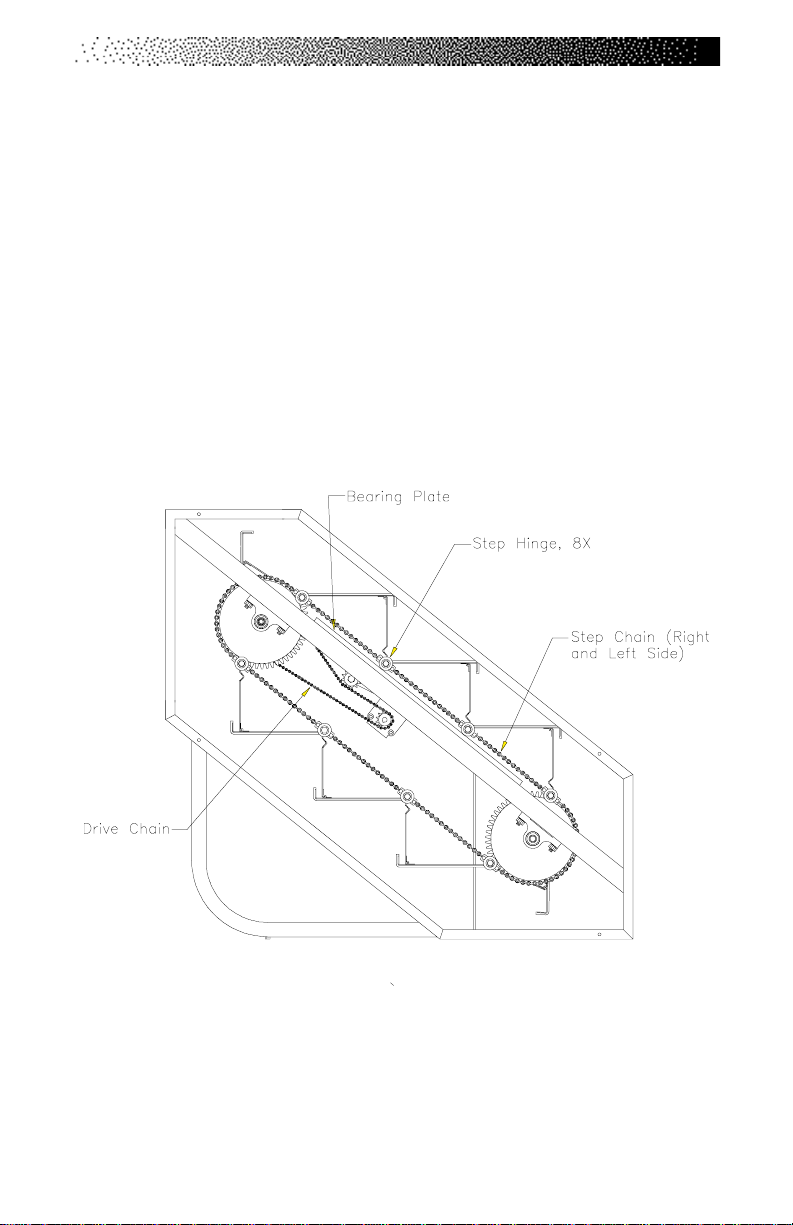
The StairMaster® Stepmill® 7000 PT exercise system has six components that
require periodic lubrication: the drive chain, the two step chains, the two bearing
plates and the step hinges. These parts are shown in the figure below. You will
need to remove the side covers to lubricate the chains and the bearing plates.
1. Place a protective mat on the floor while you are lubricating your
machine. A rubber floor mat is available from StairMaster Health & Fitness
Products, Inc.
Page 33
Page 41
MAINTENANCE INSTRUCTIONS
2. Lubricate the chains monthly with 30W motor oil. Drip the oil onto the
chain plates and rollers. Let the oil soak in for a few minutes and then
remove any excess oil with a dry rag.
3. Remove the chains every three months to thoroughly clean and lubricate
them. Use a mild degreaser and a stiff brush to remove dirt and corrosion
from the chain. Read the instructions on the degreaser container before
using.
4. Clean each bearing plate and lubricate it with multipurpose grease every
three months. The plate is lubricated to reduce friction when the step
shaft bearings roll over the plate.
5. Once per month, use 30W motor oil or brush light bearing grease into the
step hinges to lubricate the hinges and to prevent corrosion. Wipe off all
excess lubricant.
WARNING
!
Page 34
TO REDUCE THE POSSIBILITY OF SLIPPING, BE SURE
THE STEP AREA IS FREE OF GREASE OR OIL. WIPE ANY
EXCESS OIL OFF THE MACHINE SURFACES.
Page 42
MAINTENANCE INSTRUCTIONS
Table 3. Recommended Preventive Maintenance Schedule
TRAP
roiretxE
secafruS
elosnoCnaelCepiWyliaDretaWA/N
tleBV-yloP
niahCpetS
ylbmessA
niahCevirD
DEDNEMOCER
NOITCA
naelCyliaD
dnatcepsnI
fitsujda
yrassecen
etacirbuL
dnanaelC
etacirbul
etacirbuL
dnanaelC
etacirbul
YCNEUQERFRENAELCTNACIRBUL
roylkeeW
sruoh07retfa
esufo
roylhtnoM
003retfa
esufosruoh
roylretrauQ
009retfa
esufosruoh
roylkeeW
sruoh07retfa
esufo
roylretrauQ
009retfa
esufosruoh
A/NA/N
A/N
dliM
A/N
&paoS
retaw
resaerged
dliM
resaerged
A/N
rotomW03
lio
rotomW03
lio
rotomW03
lio
rotomW03
lio
roylhtnoM
gniraeB
etalP
segniHpetSetacirbuL
dnanaelC
etacirbul
003retfa
esufosruoh
roylretrauQ
009retfa
esufosruoh
A/N
yrd,naelC
gar
lio
esaerg
*Note: Use of lubricants other than those so specified will result in diminished
performance and a shorter life span for that part.
Page 35
rotomW03
esoprupitluM
Page 43

TROUBLESHOOTING
GENERAL TROUBLESHOOTING GUIDELINES
This section outlines several tests to systematically identify and isolate the
cause of problems in the electrical system and the drive train. This troubleshooting section is organized into four basic problem sections: Electrical System,
Console Diagnostics, Speed Control, and the Drive Train. The first step is to
identify the problem. Once you have identified the problem, perform all the tests
in exactly the same order as written. Refer to the “Parts Removal and Replacement” section of this Manual for all disassembly and assembly instructions. To
order a replacement part, or to get help with the troubleshooting process,
contact our Customer Service Department at 800-331-3578. International
customers should contact their local distributor or call 425-823-1825.
TROUBLESHOOTING THE ELECTRICAL SYSTEM
The electrical system consists of: the power supply, main cable, relay board, load
resistor, and the console. In order to identify the component that is causing the
problem, you must systematically test the system. You will need a volt-ohm
meter (multimeter) to conduct portions of the following procedures. The console
and power supply are not serviceable by the owner. If either of these parts are
inoperable, they must be replaced. Opening the console or the power supply will
void the warranty.
The Console Fails to Power Up
A. Perform a visual check of the machine. Check the following things first:
1. Is the power supply plugged in?
2. Is the indicator light lit on the power supply? If it is, proceed to step
#3. If the light is not on, go to step B.
3. Replace or exchange your console with a console you know is good
and retest the machine.
B. Verify AC power.
1. Disconnect the AC power cord from the AC wall outlet.
Page 36
Page 44

TROUBLESHOOTING THE ELECTRICAL SYSTEM
2. Verify that the AC wall outlet is supplying the correct power in one of
two ways: a) Use a voltmeter to verify that the AC line voltage is
between 108 and 130 VAC (or between 208 and 240 VAC, if applicable)
at the AC wall outlet; or b) Plug in an alternate AC-powered device (a
lamp, for example). If the AC wall outlet is supplying the correct power,
proceed to step #3. If the voltage is outside the range or if the device
does not work when plugged into the AC wall outlet, consult an
electrician for further assistance and then retest the AC wall outlet.
3. Plug the AC power cord into the wall outlet and proceed to the next
section.
C. Verify DC power.
1. Make sure that the AC power cord is plugged in and that the AC wall
outlet is delivering the proper voltage.
2. The indicator light should be lit. If it is, proceed to step #3. If the
indicator light is still not lit, replace the power supply and test the new
power supply.
3. Disconnect the cable from the DC power connector located on the
bottom cover. Use a DC voltmeter to verify 12-19 VDC at the end of
the DC cable. Pin #1 is negative and pin #2 is positive. Proceed to step
#4 if the VDC is within the range. Replace the power supply if the VDC
is outside the range and test the new power supply.
4. Remove the right side cover. Reconnect the DC power cable to the
machine. Locate the relay/resistor circuit board located just inside the
frame, midway between the top and bottom steps (refer to Wiring
Diagram 1). There are three red indicator lights along the bottom edge
of the relay assembly circuit board. They are labeled, from top to
bottom: Field, Power , and Relay. Ensure the black and white wire
power connector (labeled J2 on the relay resistor circuit board) is
securely connected to the relay resistor circuit board.
a. The Power light should be lit. If it is, go to step #5. If it is not,
disconnect the power connector from the J2 position on the relay
Page 37
Page 45
TROUBLESHOOTING THE ELECTRICAL SYSTEM
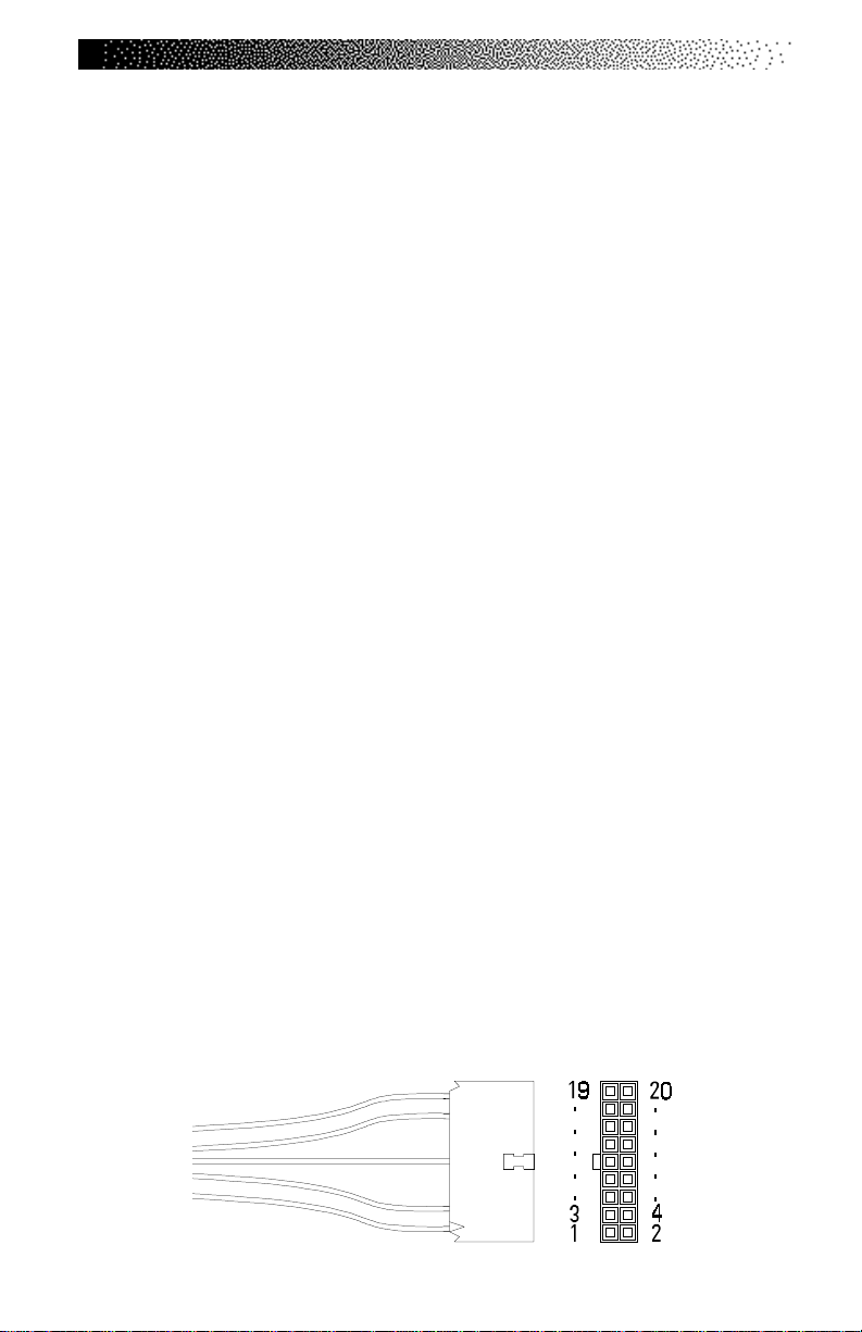
assembly circuit board (refer to Wiring Diagram 2). Use a DC
voltmeter to measure the VDC at the power connector. Pin #1
is negative and Pin#10 is positive. The reading should be between
12 and 19 VDC. If you are not getting power to the connector,
replace the power connector assembly and retest.
b. If you are getting the correct voltage at the power connector,
reconnect it to the J2 position on the relay assembly circuit
board. Disconnect the main cable connector at the J1 position of
the relay assembly circuit board. Check the VDC reading at the
silver tabs on the relay assembly circuit board. Tab #4 (labelled +/
WHT) is positive and tab #5 (labelled GND/BLK) is negative (refer
to Wiring Diagram 2). You should get a reading between 12 and
19 VDC. If your reading is not within the range, replace the relay
assembly circuit board and retest.
c. If you are getting the correct voltage at tabs #4 and #5, check the
VDC reading at the connector labeled position J1 on the relay
assembly circuit board. Pin #4 is positive and pin #5 is negative.
You should get a reading between 12 and 19 VDC. If your
reading is not within the range, replace the relay assembly circuit
board and retest.
d. If all of the above power tests produce VDC readings that are
within range and the Power indicator light is still not lit, the
Power indicator light is probably inoperable. Replace the relay
assembly circuit board, reconnect all wires, and retest.
5. Remove the console and disconnect the console cable. Use a DC
voltmeter to measure the VDC at pin #1 (negative) and pin #10 (positive)
of the console cable connector. You should get a reading between 12
and 19 VDC. If the reading is not within the range, replace the cable
assembly and retest.
Page 38
Page 46

CONSOLE DIAGNOSTIC TESTS
The following tests are performed while the console is in the “SELECT
WORKOUT” mode. If the console fails any test, the console should be replaced or
exchanged. To return to the “SELECT WORKOUT” mode, press either [CLEAR] or
[START/STOP] while in the DIAGNOSTIC mode. Please note that there may be
addition verbiage on the display other than is listed in this manual. The Stepmill
7000 PT console is used on other StairMaster® equipment.
Diagnostic Codes
[ ^ ] [ 6 ] [ 0 ] Test display
[ ^ ] [ 6 ] [ 1 ] Test keyboard
[ ^ ] [ 6 ] [ 2 ] Test serial port
[ ^ ] [ 6 ] [ 3 ] Test alternator
[ ^ ] [ 6 ] [ 4 ] -N/A-
[ ^ ] [ 6 ] [ 5 ] -N/A-
[ ^ ] [ 6 ] [ 6 ] Test Tach
[ ^ ] [ 6 ] [ 7 ] - [ 6 ] [ 9 ] -N/A-
The Display Test
During the display test, the console screen alternates between all LCD segments
turned on, and sample program profile screen at a 2-second rate.
®
1. Press [ LEVEL: ^ ], [ 6 ], [ 0 ], [ENTER]. The console will display
“DISPLAY TEST”.
2. All LCD segments will turn on for 2 seconds and then a sample
program profile will be displayed for 2 seconds. Press [CLEAR] to end
the test.
The Keypad Test
Perform this test if you are having trouble entering data into the console.
During the test, pressing any key displays that key name on the message line.
Press [CLEAR] to exit.
1. Press [ LEVEL: ^ ], [ 6 ], [ 1 ], [ENTER] to start the test.
Page 39
Page 47

CONSOLE DIAGNOSTIC TESTS
2. Firmly press each button except [CLEAR]. The name of the key will be
shown in the display window. Press [CLEAR] to end the test.
The Serial Port Test
This test verifies that the RS 232 port used for linking to commercial entertainment systems is working. You must have the loop-back cable assembly, pn
040051-001 to perform this test.
1. Insert the loop-back cable assembly into the RS 232 port on the back
of the console.
2. Press [ LEVEL: ^ ], [ 6 ], [ 2 ], [ENTER], to start the test.
3. The console will run a diagnostic test and then display either “PASS”
or “FAIL”. Replace the console if it fails this test.
The Alternator Test
Use this test to verify the alternator field routines of the console. You will need
to briefly exercise on the machine for this test.
1. Press [ LEVEL: ^ ], [ 6 ], [ 3 ], [ENTER], to start the test.
2. For “Field on” press [ LEVEL: ^]. Step on the machine for
approximately 10 to 15 seconds. If full resistance is achieved during
this time, your console has correct current flow. If no resistance is
achieved, either the console or the alternator is bad. See the
electrical troubleshooting portion of this manual to isolate and test
the alternator. Replace the console if the alternator is good.
3. For ‘Field off” press [ LEVEL: V]. Step on the machine for
approximately 10 to 15 seconds. You should not get resistance with
the field turned off. Press [CLEAR] to end the test.
Page 40
Page 48

CONSOLE DIAGNOSTIC TESTS
The Tach Test
If you do not have resistance, perform the tach test. The tach test will tell you the
tach signal, in revolutions per minute (RPMs), picked up by the console.
1. Press [ LEVEL: ^ ], [ 6 ], [ 6 ], [ENTER]. The console will display
“TAR TACH ACT”. The target tach speed of 2000 RPMs will be shown
in the upper left corner of the display window. The actual tach picked
up by the console will be shown in the upper right corner of the
display window.
2. Start stepping on the steps. The number in the right hand corner of
the console should increase to 2000 RPMs (+/- 200). If the tach signal
picked up by the console is less then 1900 RPMs then there is a
problem in the AC tach circuit - either with the console software,
alternator (check the AC tach wire, the field wire, the diode, and the
terminal posts), or the main cable.
Error Reporting
The console will display various error messages in the display window. The total
amount of errors will be displayed in the upper right numeric window. Note that
only the highest priority reported error will be displayed. Errors are handled in
two ways. One as a non-fatal “WARNING” which will display the text message
but continue system operation until the user presses the [CLEAR] key. The second way is as a fatal “ERROR” which will stop the exercise and return the system
to an idle intensity state. The console will display the error text and not let the
user restart the programs unless power has been turned off and then back on.
The following microprocessor errors require a console replacement;
ALU ERROR, TIMER ERROR, and STATIC RAM ERROR.
Resetting the power may clear the following microprocessor errors;
EEPROM ERROR, and PROGRAM ERROR. If resetting the power doesn’t work, the
console may need to be replaced.
Page 41
Page 49

CONSOLE DIAGNOSTIC TESTS
The Telemetry (Polar®) Heart Rate Test
The telemetry heart rate system is made up of the console, the heart rate receiver, and the chest strap (available separately). You can test each component
by performing the following steps:
1. You will need to put a chest strap on in order to test the telemetry
heart rate. Before you put on the chest strap, wet the two contact
patches. Secure the chest strap as high under your pectoral muscles
(chest) as is comfortable. The chest strap should fit snugly,
comfortably, and allow normal breathing.
2. A flashing
beats per minute, will show next to the heart icon. If the heart icon
does not show, or if your heart rate is not displayed on the console
then you have a problem with either the console, chest strap, or
heart rate receiver.
3. Verify that the console software has been set up to receive telemetry
(see the heart rate monitoring section of this manual). Note that
holding the contact heart rate sensors (if enabled) can inhibit the
telemetry heart rate input from working.
4. Test your chest strap with a machine that you know is working, or
with a heart rate watch that you know is working.
5. If possible, replace or exchange your console with a machine that you
know is working and retest the machine.
6. Excess false heart rate detection: the telemetry receiver located in the
console is susceptible to mechanical vibration as well as external electrical interference. Hitting the console or the frame may momentarily
cause errant heart beat detection - this is normal. If excessive false
heart beats appear only during workouts, check that the console cable
is not curled up behind the console. Pull as much of the cable down and
away from the console as possible. False heart beats while the machine
is idle are most likely due to external interference. Try plugging the machine into a different outlet, or moving it to a new location.
♥ should be displayed on the console. Your heart rate, in
Page 42
Page 50
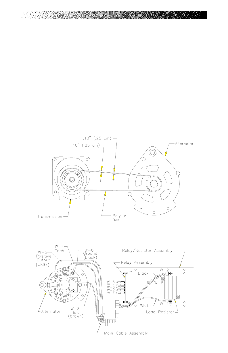
SPEED CONTROL PROBLEMS
If you have problems with erratic speed control while operating the machine, the
cause may be either electrical or mechanical in nature. You will have to remove
the side covers to conduct most of these tests.
A. Perform a visual check of the machine. Check the following things first:
1. Inspect the Poly- V belt for proper tension and excessive wear. A loose
belt will cause excessive noise and wear . The machine will run sluggishly if the belt is too tight.
2. Replace a worn or frayed Poly-V belt. Adjust the belt so that there is 1/
10" (0.3 cm) deflection at a point midway between the alternator and
transmission pulleys with fingertip pressure (See Drawing Below).
3. Check for proper wire connections on the alternator, relay assembly
circuit board, and load resistor (See Drawing Below).
Page 43
Page 51
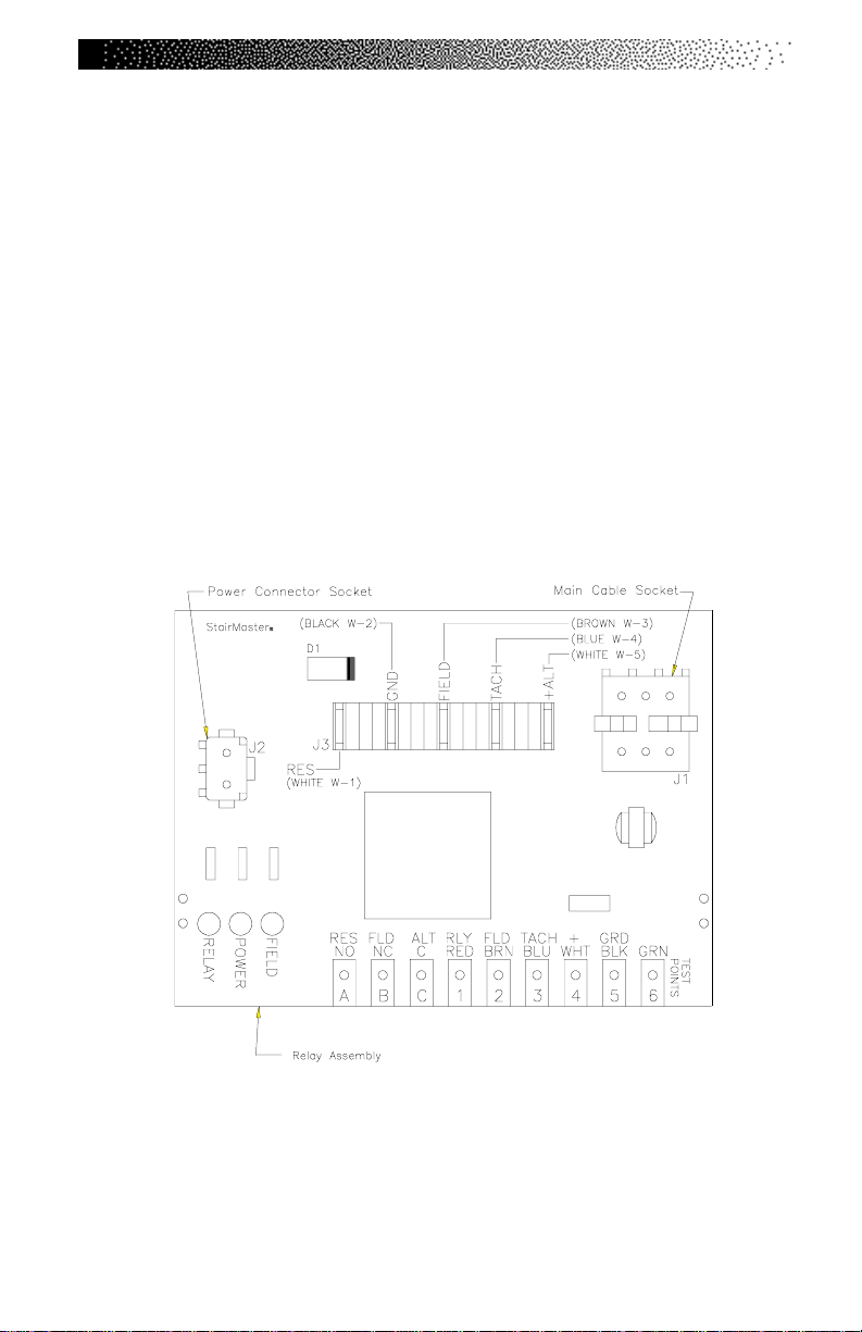
SPEED CONTROL PROBLEMS
4. Replace or exchange the console with another console you know is
good and retest the machine.
B. Check the relay assembly circuit board while the console displays "SELECT
WORKOUT." You will need an assistant to complete the test of the
relay assembly circuit board.
1. Remove the right side cover. Locate the relay assembly circuit board
located just inside the frame, midway between the top and bottom
steps (refer to Wiring Diagram). There are three red indicator lights
along the bottom edge of the circuit board. They are labeled, from top
to bottom: Field, Power , and Relay. Ensure the black and white wire
power connector (labeled J2 on the relay assembly circuit board) is
securely connected to the relay assembly circuit board (refer to Figure
Below).
2. If the Power light is lit, go to step #3. If it is not, perform the tests as
described in step 4b - c of the “Console Fails to Power Up” section.
3. The relay indicator light should be lit. If it is lit, proceed to step #5. If it
is not, use a jumper wire on the relay assembly circuit board. Jump
the silver tabs #1 (labeled RLY/RED) and #5 (labeled GRD/BLK) (refer
Page 44
Page 52

SPEED CONTROL PROBLEMS
to Figure on page. 34). The relay indicator should light up. If it does, go
to step #4. If the relay indicator does not light up, the relay assembly
circuit board must be replaced. Replace the relay assembly circuit
board and retest the machine.
4. You must check the cable assembly for continuity if the relay indicator
lit up when you jumped tabs #1 and #5.
a. Unplug the main cable from the position labeled J1 on the relay
assembly circuit board. Disconnect the console cable from the
back of the console. Set your multimeter to the continuity check
mode; on most meters, this will be the resistance or ohms setting.
b. Place one lead of the multimeter on pin #1 at the console
connector end of the console cable (refer to Wiring Diagram).
Place the other lead on pin #1 at the end of the main cable you
disconnected from the relay assembly circuit board. You will get a
reading of near zero ohms if there is continuity in the cable
assembly.
c. Check continuity in both ends of the main cable assembly at pin
#5.
d. If there is no continuity in the cable assembly at either pin,
replace the cable assembly and retest. If there is continuity in the
cable assembly at both pins and the relay resistor indicator is not
lit, the console is inoperable and must be replaced.
5. Have your assistant step on the staircase (leave the console in the
A TTRACT mode) while you check the field indicator light. It should be
flickering. If it is and you still have a speed control problem, go to step
#6.
If it is not flickering, ensure the following: the console cable is
connected to the console; the console/main cable connection is
secure; the connector at position J1 on the relay assembly circuit
board is securely connected; that there is continuity in the cable
assembly. To check for continuity:
Page 45
Page 53

SPEED CONTROL PROBLEMS
a. Unplug the connector at position J1 on the relay assembly circuit
board. Disconnect the console cable from the back of the
console. Set your multimeter to the continuity check mode; on
most meters this will be the resistance or ohms setting.
b. Place one lead of the multimeter on pin #2 at the console
connector end of the console cable. Place the other lead on pin
#2 at the end of the main cable you disconnected from the relay
assembly circuit board. You will get a reading of near zero ohms if
there is continuity in the cable assembly.
c. If there is no continuity in the cable assembly, replace it and
retest. If there is continuity in the cable assembly and the field
indicator light is still not flickering, contact the Customer Service
Department at 800-331-3578 for further assistance.
6. If the field indicator was flickering while your assistant was on the
machine and you still have a problem with speed control, you need to
test the alternator.
a. Disconnect the white wire (labeled positive output on the
alternator) and the brown wire (labeled “Field” on the alternator).
Use a jumper wire to jump the Field and positive output terminals
of the alternator.
Page 46
b. Have your assistant step onto the staircase. Does the staircase
slow down? If it does not, you need to replace the alternator. If
the staircase does slow down, contact the Customer Service
Department for further assistance.
c. Replace or exchange the alternator with another alternator you
know is good and retest the machine.
d. Test the load resistor as outlined in the "Load Resistor Test"
section of this Manual. If the speed control problem still exists,
contact the Customer Service Department at (800) 331-3578 for
further assistance.
Page 54
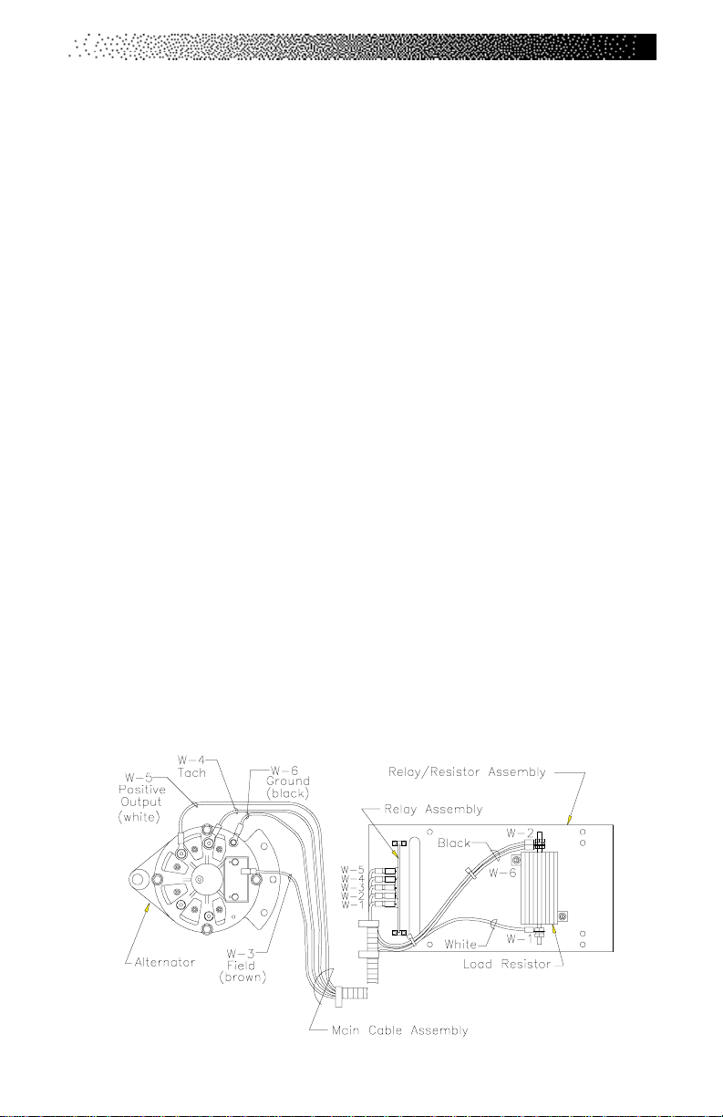
LOAD RESISTOR TEST
The alternators are heavy-duty models designed to withstand the rigors of
commercial use. One possible reason for repeated failure is an inoperable load
resistor. To test the load resistor:
1. Unplug the AC power cord from the AC wall outlet.
2. Locate the load resistor mounted to the relay board assembly just under
the staircase.
3. Disconnect one black wire from the resistor (See Drawing Below).
4. Set your multimeter for R x 1 or the lowest available resistance range. If
you have an analog multimeter, touch the two leads together and adjust
the meter for a zero reading.
5. Place one lead on Tab A and one lead on Tab 5 of the relay assembly
circuit board (See Drawing Below). You should get a reading of
approximately 1.0 ohm or less.
6. Replace the load resistor if the reading is out of range and retest the new
load resistor.
7. Reconnect the AC power cord and reinstall the right side cover.
8. If the problem still exists, contact the Customer Service Department at
(800) 331-3578 for further assistance.
Page 47
Page 55
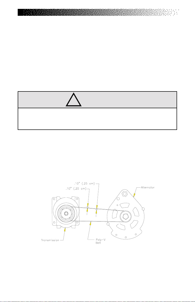
TROUBLESHOOTING THE DRIVE TRAIN
If you hear a grinding or clicking noise, or experience excessive vibration during
exercise, or if the steps are not functioning properly, you probably have a
problem in the drive train. Attempt to isolate the problem area by performing the
following tests in precisely the order listed below. Refer to the “Parts Removal
and Replacement” Section of this Manual for all disassembly and assembly
instructions.
1. Unplug the power supply from the AC wall outlet and remove the side
covers.
!
WARNING
TO REDUCE THE RISK OF INJURY, DO NOT OPERATE THE MACHINE
WHILE THE SIDE COVERS ARE REMOVED. DO NOT ROTATE THE STAIRS
WHILE ANYONE'S HANDS ARE INSIDE THE MACHINE.
2. Check the condition and the tension level of the Poly-V belt. Replace the
belt if it is excessively worn.
a. Adjust the tension level so that you can deflect either side of the
belt 1/10" (0.3 cm) at the center between the alternator and the
transmission pulleys (See Drawing Below). Noise can be generated
by a belt that is too tight or too loose.
b. If the noise is still present, remove the Poly-V belt and rotate the
staircase without standing on it. With the Poly-V belt removed, the
staircase will rotate very quickly.
c. If the noise no longer exists, replace the alternator.
Page 48
Page 56

TROUBLESHOOTING THE DRIVE TRAIN
3. Check the condition of the alternator.
a. Unplug the alternator from the relay board and remove the Poly-V
belt.
b. Spin the alternator pulley with your fingers. It should spin freely and
remain spinning for at least one and one-half revolutions. If it does
not spin as it should, the bearings may be bad and the alternator
should be replaced.
c. If the pulley does spin freely, check the alternator for noise,
roughness, or the presence of black powder inside the alternator or
near the outside of the case. If any of these conditions exist, the
brushes may be bad and the alternator should be replaced.
d. Reconnect the Poly-V belt and adjust the belt tension.
4. Check the drive chain mechanism. Rotate the stairs and look for chain
links that do not flex as the chain travels over the sprockets. If the links are
frozen or sticking, replace the chain.
5. Check the transmission.
a. Rotate the steps by hand and listen for the noise.
b. If you hear the noise, remove the drive chain and the Poly-V belt.
Rotate the steps by hand again and listen for the noise. If the noise
has gone away, replace the transmission.
6. Check the step chain assemblies.
a. Have your assistant slowly exercise on the machine. Observe the
staircase. If the staircase moves to the left or right during exercise,
ensure the set screws in the bearing adjusters are tight.
b. Rotate the stairs and look for chain links that do not flex as the chain
travels over the sprockets. If the links are frozen or sticking, replace
the chain.
Page 49
Page 57
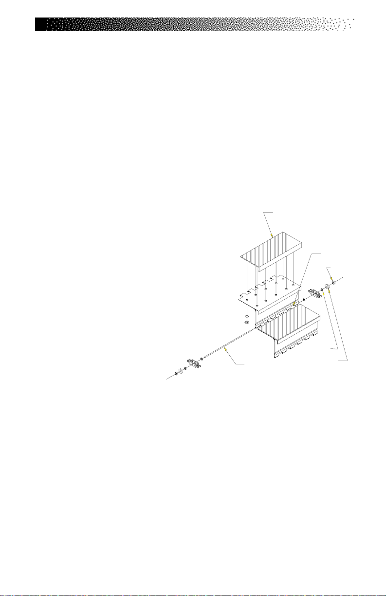
TROUBLESHOOTING THE DRIVE TRAIN
7. Check the condition of the upper and lower sprocket assemblies. Replace
the sprocket assembly if it is worn excessively, has broken teeth, or if it is
bent.
8. Check the alignment of the upper and the lower sprocket assemblies. The
outside face of the upper and lower sprockets should be 1-11/16" (4.3 cm)
from the outside edge of the left frame rail. Loosen the nuts on the pillow
block bearing collars and tighten or loosen the bearing adjuster set screws
until the distance to both sprockets is correct. Tighten the pillow block
bearing nuts and verify the distance.
9. Check the step assembly.
Step Tread
a. Rotate the steps and check the
hinges, step shafts, washers, and
bearings (See Figure to Right) for
Step Hinge
wear, corrosion and lack of
lubrication. Replace any worn
parts.
b. Ensure the nuts at each step
shaft end are tight.
4 X Washer
Step Shaft
2 X Bearing
10. Reinstall all parts. If the problem still exists, contact the Customer Service
Department at 800-331-3578 for further assistance.
2 X Nut
Page 50
Page 58
PARTS REMOVAL AND REPLACEMENT
COVERS
!
WARNING
TO REDUCE THE RISK OF INJURY, DO NOT OPERATE THE MACHINE WHILE
THE SIDE COVERS ARE REMOVED. DO NOT ROTATE THE STAIRS WHILE
ANYONE'S HANDS ARE INSIDE THE MACHINE.
There are five covers on the machine: two side covers, a back cover, a bottom
cover, and a top cover. The side covers overlap the top cover. The side covers
must be removed before the top cover and/or the bottom cover can be removed.
All covers are held in place with reusable plastic fasteners (refer to Figure 5
for their location). To remove the fasteners, slide either end of the fastener
removal tool under the edge of the pin head (refer to Figure 6). The pin should not
be removed. Pull the cover away from the frame. Do NOT use the fastener
removal tool or any other sharp tool to pry out the fastener base because you
may damage the covers - use the fastener removal tool to remove the pin.
To reinstall the fastener, insert the base of the fastener through the cover
and into the frame. When the base is in place, push the pin in all the way to
secure the fastener.
Side Covers
1. Remove the 14 fasteners on each side cover.
2. Pull the cover away from the frame.
Top Cover
1. Remove both side covers.
2. Lift the top cover away from the frame.
3. Set the top cover in place. Secure the side covers to complete
reinstallation.
Page 51
Page 59

PARTS REMOVAL AND REPLACEMENT
Back Cover
1. Remove the 8 fasteners and lift the back cover away from the frame.
2. Align the holes in the frame and the back cover. Secure the back cover
with the 8 fasteners.
Bottom Cover
1. Remove both side covers to gain access to the bottom cover fasteners.
2. Disconnect the DC power cable.
3. Remove the six fasteners and remove the bottom cover from the frame.
4. Reinstall the bottom cover, then the two side covers. Remember to
connect the DC power cable.
CONSOLE
1. Locate the mounting knobs on the back of the console (See cutaway view
Below).
2. Loosen and remove the four mounting knobs and lock washers.
3. Lift up the console and unplug the console cable from the back of the
console.
4. Remove the console from the frame.
5. Reinstall the console by reversing
the steps.
Page 52
Page 60
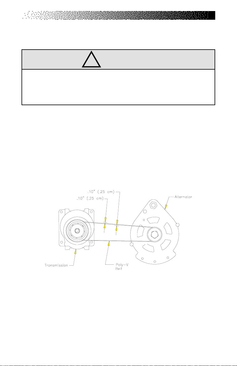
PARTS REMOVAL AND REPLACEMENT
POLY-V BELT
!
WARNING
THE POLY-V BELT MUST BE ADJUSTED SO THAT THE CENTER OF EITHER
SIDE CAN BE DEFLECTED 1/10" (0.3 CM) FROM ITS CENTER LINE WITH FINGER-
TIP PRESSURE. A TIGHT BELT WILL CAUSE SLOW AND SLUGGISH OPERATION; A
LOOSE BELT WILL CAUSE EXCESSIVE NOISE AND BELT WEAR.
1. Remove the left side cover.
2. Loosen the adjustment bolt that mounts the alternator to the slotted
alternator brace then loosen the pivot nut.
3. Pivot the alternator forward to loosen the belt. Remove the Poly-V belt.
4. When reinstalling the Poly-V belt, pivot the alternator forward or back as
necessary to allow 1/10" (0.3 cm) of play on either side of the belt (See
Figure Below).
5. Tighten the adjustment bolt and verify the Poly-V belt tension.
DRIVE CHAIN
1. Remove the left side cover.
2. Remove the retaining clip and retaining plate from the drive chain master
link. Do not remove the master link from the drive chain yet.
Page 53
Page 61
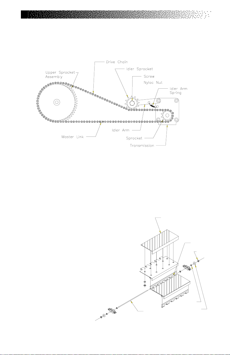
PARTS REMOVAL AND REPLACEMENT
3. Push up on the idler arm with one hand to relieve the tension on the
drive chain (See Drawing Below). Remove the master link from one end of
the drive chain and remove the drive chain from the sprockets.
4. Install the new drive chain by reversing the steps.
STEP ASSEMBLY
1. Remove the right and the left side covers.
2. Rotate the stairs until the step you want to remove is positioned in the
middle of the staircase.
Step Tread
3. Loosen and remove the nut from one end
of the step shaft on both the upper and
the lower hinges of that step (See
Figure to Right).
4. Remove the bearing and the washer
from each step shaft.
5. Grasp the opposite step retaining
nut with pliers or locking pliers.
Pull the step shaft out of the
upper and lower step hinges.
Step Shaft
4 X Washer
2 X Bearing
Page 54
Step Hinge
2 X Nut
Page 62
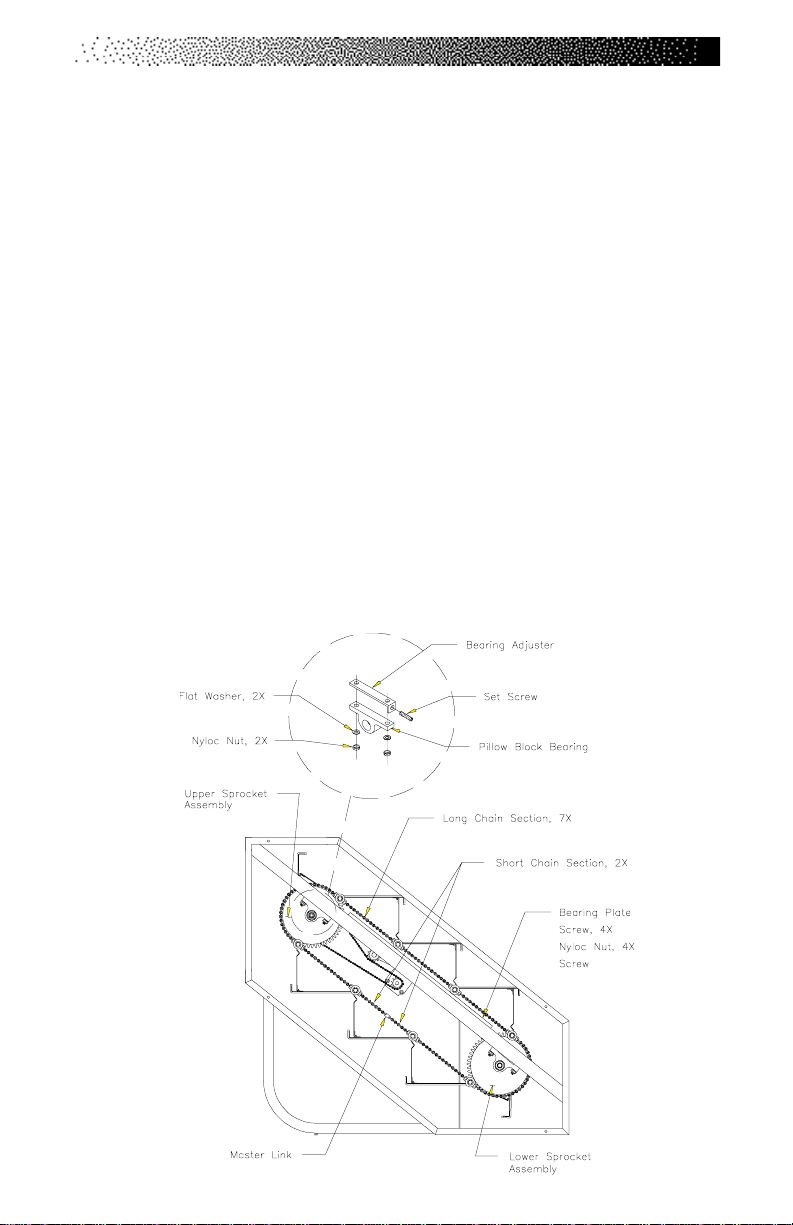
PARTS REMOVAL AND REPLACEMENT
Be careful to not lose the washer located between the step and the
modified link.
Note: Each step assembly weighs approximately 15 lbs. Be aware of finger
placement when removing the step assembly.
6. Reinstall the step by reversing the procedures.
STEP CHAIN ASSEMBLY
1. Remove the right and the left side covers.
2. Rotate the stairs to position the step chain master link on the lower span
of the chain. It may be necessary to reduce the chain tension to remove
the master link. Perform the following steps to reduce the chain tension:
• Count and write down the number of exposed threads on the top
bearing adjuster set screw for a reference when you reassemble the
parts (SeeFigure Below).
Page 55
Page 63

PARTS REMOVAL AND REPLACEMENT
• Loosen the nuts on the pillow block bearing housing.
• Loosen the bearing adjustment set screw until the chain tension level
is relieved to a point where the master link may be disconnected.
3. Remove the master link.
4. Using the old master link, connect the new chain assembly to the lower
half of the old chain assembly.
5. Remove the nut from the step shaft above the master link. It may be
necessary to place another 5/16"-18 nut on the opposite end of the step
shaft to gain leverage and remove the nut.
6. Remove the bearing, the outer step shaft washer and the modified link of
the old step chain assembly from the step shaft.
7. Place the modified link of the new step chain assembly on the step shaft.
Reinstall the outer step shaft washer, bearing and nut.
8. Rotate the steps until the next step shaft is in approximately the same
place as the previous step shaft.
9. Repeat steps 6-8 until the new chain assembly is installed on the
remaining step shafts.
10. Remove the master link connecting the old chain with the new chain.
11. Connect the new chain assembly together with the master link. Tighten
the bearing adjustment set screw until the same number of threads as in
step 2 are exposed. Tighten the nuts on the pillow block bearing housing.
12. You should consider replacing the opposite step chain so that both chains
will wear equally.
13. Reassemble the machine in reverse order.
Page 56
Page 64
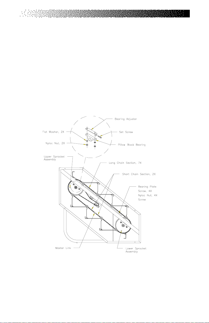
PARTS REMOVAL AND REPLACEMENT
UPPER (AND LOWER) SPROCKET ASSEMBLY
1. Remove the right and left side covers.
2. Remove all of the steps.
3. Remove the drive chain if you are removing the upper sprocket assembly.
4. Count and write down the number of exposed threads on the bearing
adjuster set screws on both sides of the machine for a reference when
you reassemble the parts (See Drawing Below).
5. Remove the right and left step chain assemblies.
6. Loosen the adjustment screws until the tips of the screws are flush with
the inside face of the bearing adjusters.
Page 57
Page 65

PARTS REMOVAL AND REPLACEMENT
7. Have an assistant support the sprocket assembly. Loosen and remove the
nuts on the pillow block bearing housing.
8. Remove the sprocket assembly from the frame.
9. Loosen the two set screws on both of the pillow block bearing collars and
remove the pillow block bearings from the sprocket axle.
10. To reinstall the sprocket assembly:
• Slide the pillow block bearings on both ends of the sprocket axle. Do
not tighten the set screw on the pillow block bearing collars yet.
• Place the bearing adjusters and the sprocket assembly onto the frame
and start the pillow block bearing housing nuts onto the frame.
• Slide the sprocket assembly toward the front of the machine while
tightening the pillow block bearing housing nuts.
• Align the sprocket assembly. The outside face of the left sprocket
should be 1-11/16" (4.3 cm) from the outside edge of the left frame
rail. Move the sprocket axle within the pillow block bearing collar as
needed to get the correct distance.
• When the distance is correct, tighten the pillow block bearing collar
set screw on the left and right sides of the machine.
• Loosen the pillow block bearing housing nuts slightly. Tighten the
bearing adjuster set screws until the exact number of threads are
exposed (refer to your notes taken earlier). Tighten the pillow block
bearing housing nuts.
• Check the alignment of the other sprocket at this time. If the distance
from the outside edge of the left frame rail to the outside face of the
sprocket is not 1-11/16" (4.3 cm), loosen the set screws on the left
and right side pillow block bearing collars and adjust the axle. Tighten
the pillow block bearing collar set screws on the machine and then go
to step 11.
Page 58
Page 66
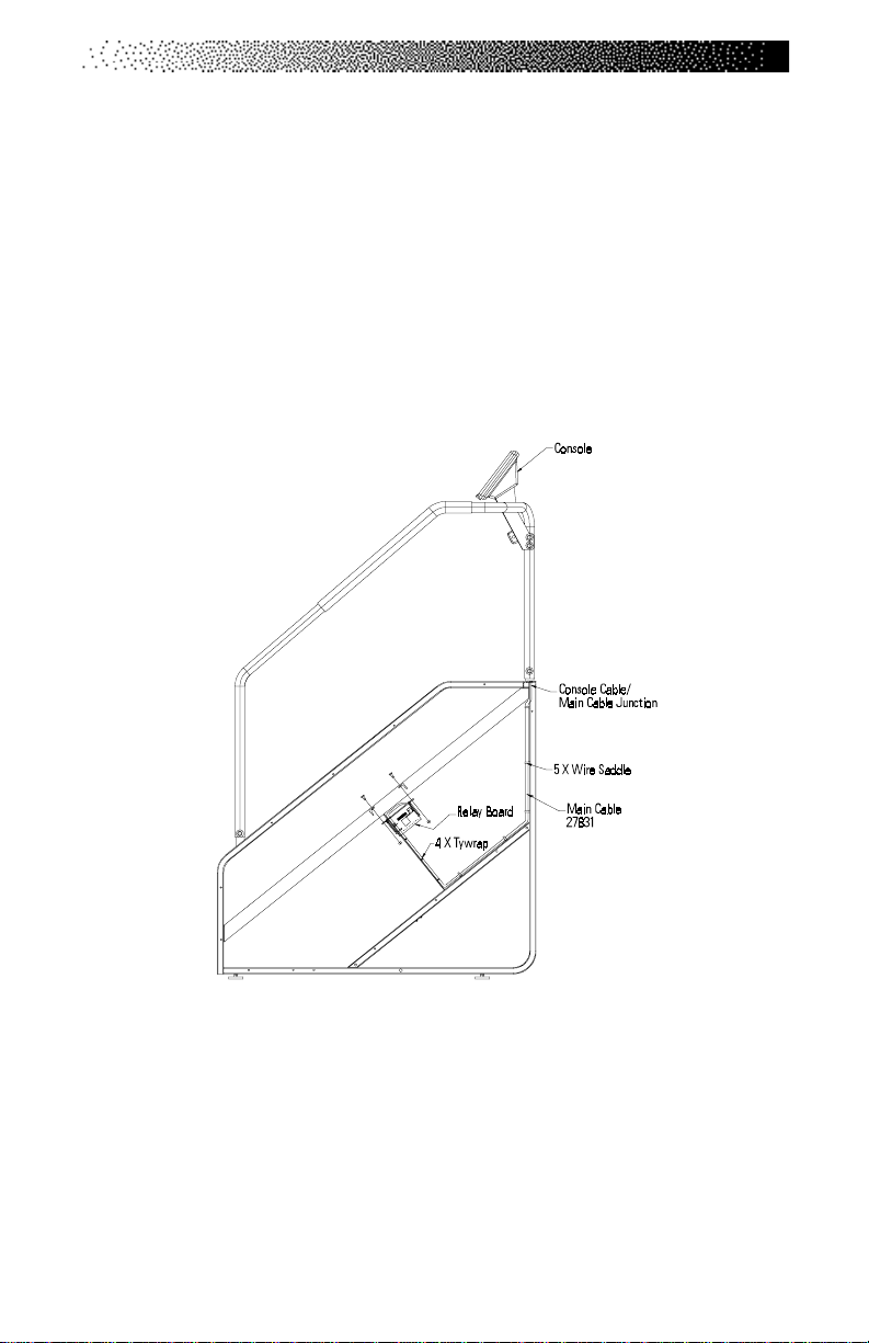
PARTS REMOVAL AND REPLACEMENT
11. Complete the reassembly of the machine by performing steps 1- 4 in
reverse order.
CABLE ASSEMBLY
1. Remove the right side cover.
2. Remove the console and unplug the console cable from the back of the
console (See Drawing Below). Unplug the plastic connectors at the console
cable/main cable junction.
3. Hold the console connector and pull the console cable up and out of the
handrails.
4. Reinstall the console cable by pushing the white plastic connector end
down through the handrails. Do not connect the console, and the main
cables.
5. Remove the main cable from the wire saddles.
Page 59
Page 67

PARTS REMOVAL AND REPLACEMENT
6. Unplug the white plastic connector labeled J1 on the relay assembly
circuit board.
7. Cut the four tyraps on the vertical support.
8. Remove the main cable from the frame.
9. To reinstall, place the main cable into the wire saddles. Reattach the cable
to the vertical support with four tyraps.
10. Plug the white plastic connector of the main cable into the relay assembly
circuit board at the spot labeled J1.
11. Plug the console cable into the back of the console. Reattach the console
to the handrail mount. Plug the connectors together at the main cable/
console cable junction.
12. Reinstall the right side cover. Reconnect the DC power cable.
TRANSMISSION ASSEMBLY
1. Remove the left and right side covers.
2. Remove the step positioned in the middle of the staircase.
3. Remove the drive chain.
4. Remove the Poly-V belt. Inspect the belt for wear. Replace the belt if it is
cracked, worn, torn, or cut.
5. Remove the transmission bracket by loosening and removing the
mounting hardware on the alternator and the transmission.
6. Remove the transmission brace by loosening and removing the mounting
hardware from the transmission and the frame.
Page 60
Page 68
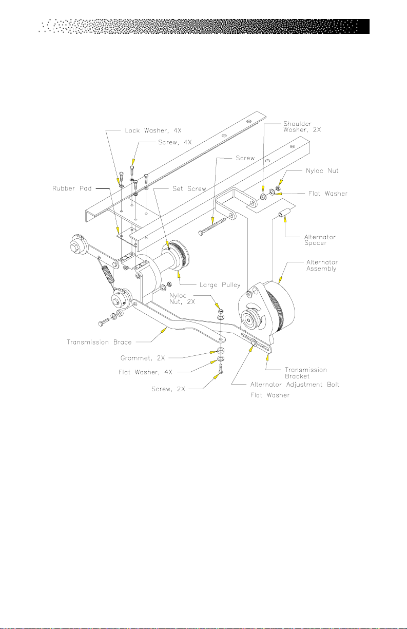
PARTS REMOVAL AND REPLACEMENT
7. Support the transmission while loosening and removing the four
transmission mounting bolts. Remove the transmission and rubber pad
from the frame (See Drawing Below).
8. Reinstall the transmission by reversing the removal procedures.
9. Ensure the Poly-V belt is tensioned according to the procedures outlined in
the “Poly-V Belt” section of this Manual.
ALTERNATOR ASSEMBLY
1. Remove the right and left side covers.
2. Remove the step positioned in the middle of the staircase.
3. Remove the wiring from the alternator terminals, noting the origin and color
of the wires removed from each terminal.
Page 61
Page 69
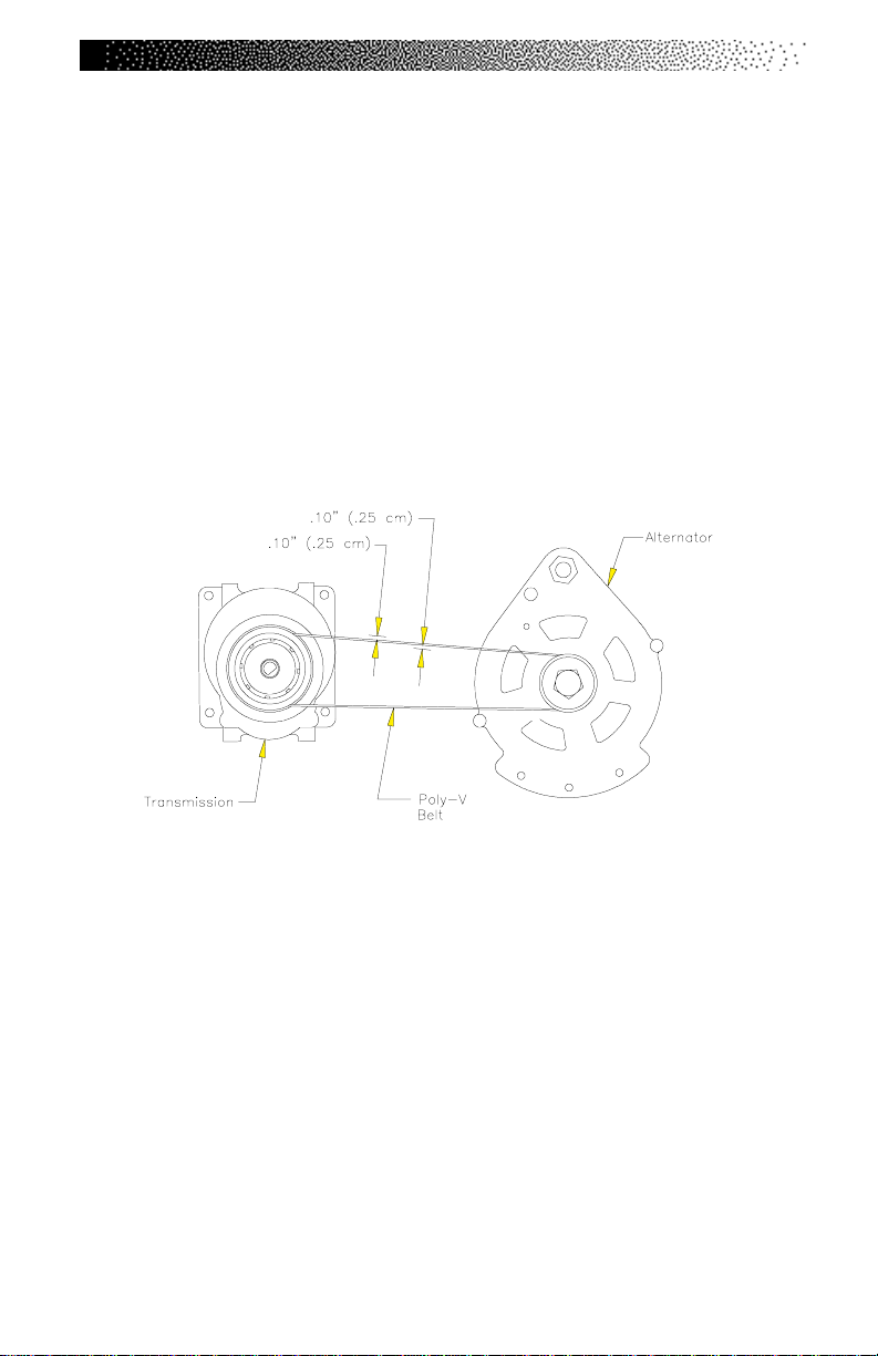
PARTS REMOVAL AND REPLACEMENT
4. Remove the Poly-V belt. Inspect the belt for wear. Replace the belt if it is
cracked, worn, torn, or cut.
5. Remove the alternator adjustment bolt (See Drawing on Pg. 51).
6. Remove the nut, bolt and mounting hardware from the alternator bracket.
Remove the alternator from the frame.
7. Reinstall the alternator by reversing the removal procedures. Be sure to
verify the wiring connections.
8. Ensure the Poly-V belt is tensioned correctly (See Drawing Below).
RELAY/RESISTOR ASSEMBLY
1. Remove the left side cover.
2. Remove the step positioned in the middle of the staircase.
3. Remove the wiring from the alternator terminals, noting the origin and color
of the wires that are removed from each terminal.
4. Unplug the main cable connector from the J1 position on the relay circuit
board.
Page 62
Page 70
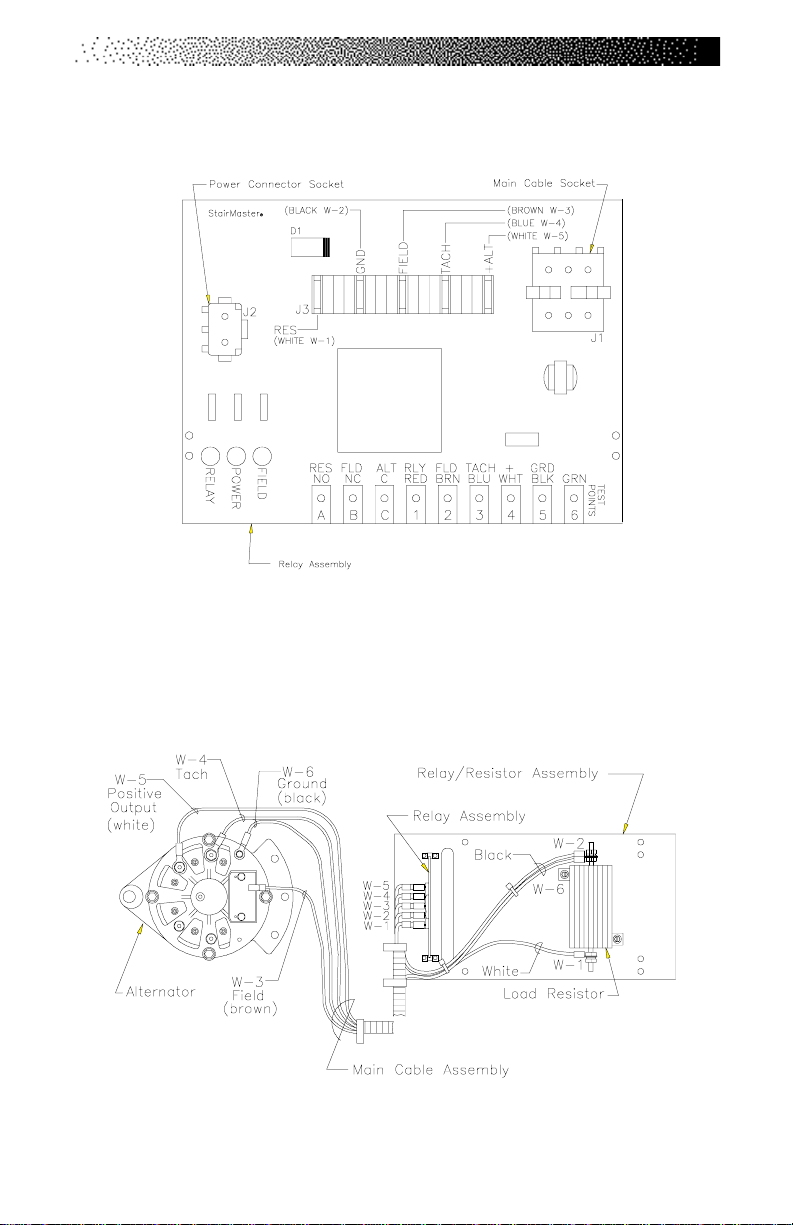
PARTS REMOVAL AND REPLACEMENT
5. Unplug the power connector from the J2 position on the relay circuit board.
6. Loosen and remove the four mounting bolts and remove the relay/resistor
assembly from the frame.
7. Reinstall the relay/resistor assembly in the reverse order. Verify the wiring
connections before attaching the side cover.
Page 63
Page 71

GROUNDING INSTRUCTIONS
The machine must be grounded. If it should malfunction or break down, grounding provides the path of least resistance for the electric current, thereby reducing
the risk of electric shock. This machine is equipped with a cord having an
equipment-grounding conductor and a grounding plug that looks like the plug
illustrated in sketch A in the Drawing below. International machines may vary. It
must be plugged into an appropriate outlet that is properly installed and
grounded in accordance with all local codes and ordinances.
!
DANGER
IMPROPER CONNECTION OF THE EQUIPMENT-GROUNDING
CONNECTOR CAN RESULT IN THE RISK OF ELECTRIC SHOCK. CHECK
WITH A QUALIFIED ELECTRICIAN OR SERVICE PERSON IF YOU ARE IN
DOUBT AS TO WHETHER THE MACHINE IS PROPERLY GROUNDED. DO
NOT MODIFY THE PLUG PROVIDED WITH THIS MACHINE. IF IT WILL NOT
FIT THE AVAILABLE OUTLET, HA VE A PROPER OUTLET INSTALLED BY A
QUALIFIED ELECTRICIAN.
A temporary adapter that looks like the adapter illustrated in sketches B and
C may be used to connect this plug to a two-pole receptacle as shown in sketch
B if a properly grounded outlet is not available. The temporary adapter should be
used only until a properly grounded outlet (sketch A) can be installed by a
qualified electrician. The green colored lug extending from the adapter must be
connected to a permanent ground such as a properly grounded outlet box cover.
Whenever an adapter is used, it must be held in place by a metal screw.
Page 64
Figure 5: Grounding System
Page 72
FCC COMPLIANCE
This equipment has been tested and found to comply with the limits for a Class A
digital device, pursuant to Part 15 of the FCC rules. These limits are designed to
provide reasonable protection against harmful interference when the equipment
is operated in a commercial environment. This equipment generates, uses, and
can radiate radio frequency energy and, if not installed and used in accordance
with the instruction manual, may cause harmful interference to radio communications. Operation of equipment in a residential area may cause harmful interference in which case the user will be required to correct the interference at his
own expense.
!
WARNING
CHANGES OR MODIFICATIONS TO EQUIPMENT NOT EXPRESSLY APPROVED BY
STAIRMASTER® HEALTH & FITNESS PRODUCTS, INC. COULD VOID THE USER’S
AUTHORITY TO OPERATE THIS EQUIPMENT.
CANADIAN DOC CLASS A COMPLIANCE
This digital apparatus does not exceed the Class A limits for radio emissions
from digital apparatus set out in the radio interference regulations of the
Canadian Department of Communications.
La présent appareil numérique ne dépasse pas les limites etablies pour les bruits
radioélectriques applicables aux appareils numériques de la Class A prescrites
dans les règlements sur le brouillage radioélectrique édicté par le Ministère des
Communications du Canada.
Page 65
Page 73

IMPORTANT PHONE NUMBERS
If you need assistance, please have both the serial number of your machine and
the date of purchase available when you contact the appropriate
StairMaster® Health & Fitness Products, Inc. office listed below.
OFFICES IN THE UNITED STATES
CORPORA TE HEADQUARTERS CUSTOMER SERVICE
12421 Willows Road NE, Suite 100 12421 Willows Road NE, Suite 100
Kirkland, WA 98034 Kirkland, WA 98034
(800) 635-2936 or (425) 823-1825 (800) 331-3578
FAX: (425) 823-9490 FAX: (425) 814-0601
www.stairmaster.com E-mail: customerservice@
stairmaster.com
INTERNATIONAL OFFICES AND DISTRIBUTORS
For technical assistance and a list of distributors in your area, please call or fax
one of the following numbers.
INTERNATIONAL DIVISION ASIA PACIFIC HEADQUARTERS
(425) 823-1825 Telephone/Fax:+81-45-590-5686
FAX: (425) 820-7505 E-mail: [email protected]
E-Mail: [email protected]
EUROPE: HEADQUARTERS
+41-91-827-3801
FAX: +41-91-827-8902
E-Mail: [email protected]
GERMANY: HEADQUARTERS
+49-2204/610-27
FAX: +49-2204/628-90
E-Mail: [email protected]
U.K.: HEADQUARTERS
+44-1908/267-345
FAX: 44-1908/267-346
E-mail: [email protected]
Page 66
Page 74
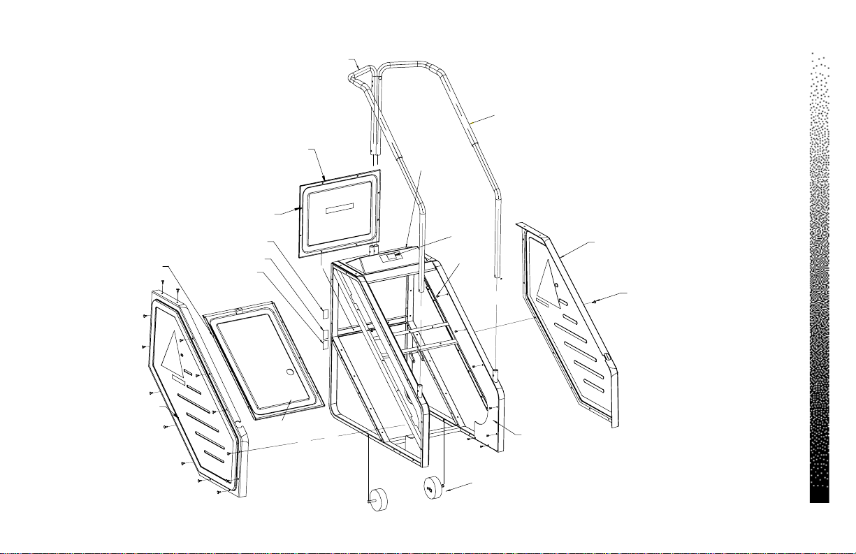
Page 67
7 X 24757
Left Side Cover
22544
8 X 22086
Distribution Decal
Serial Numbe r D ecal
Com p lian ce D e ca l
Left Ha nd rail
22947-03
Back Panel
21304
Bottom Panel
22563
Top Cover
22555
Caution Decal
23 X 24757
Right Handrail
22946-03
Inside Panel
Right - 24638
Left - 24639
Figure 6: Side Cover and Handrail Assemblies
Right Side Cover
22547
36 X 22086
FIGURES
Transport Wheel Assembly
2 X 10262
Page 75
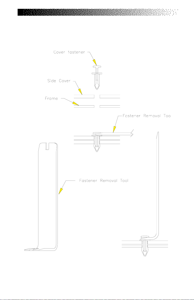
FIGURES
Figure 7: Cover Fasteners
Page 68
Page 76
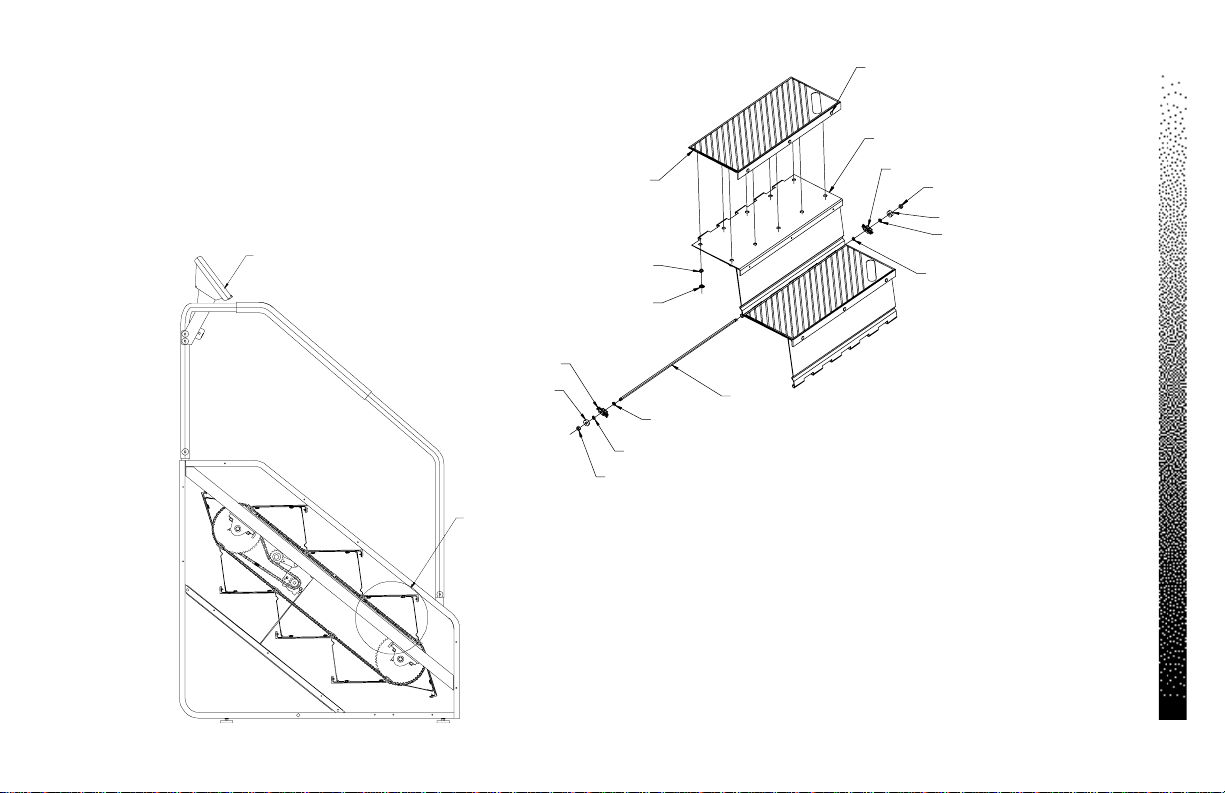
Console
Step Tread
8 X 21398
80 X 20528
80 X 20508
24 X 21363
Step Assembly (w/T read )
8 X 21396
Modified Link
(22063)
(23082)
(22128)
(22128)
Figure 8: Step Assembly
Page 69
Modified Link
Step Shaft Bearing
16 X 23082
See Detail A
(22128)
32 X 22128
Step Shaft Nut
16 X 22063
Step Shaft
8 X 20762
Detail A
FIGURES
Page 77
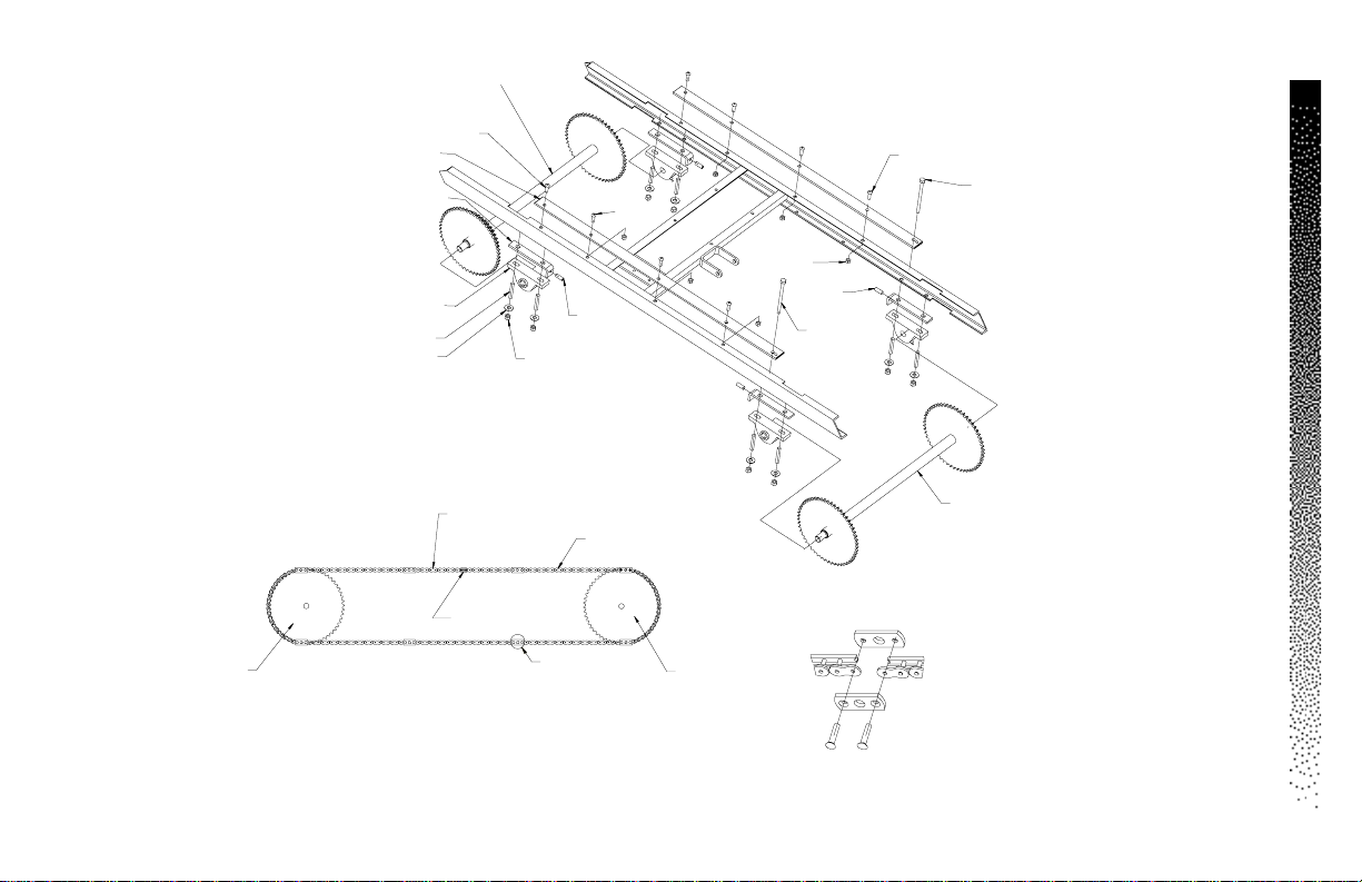
Page 70
Upper Sprocket Assem b ly
(42-Tooth Sprocket)
23424-03
8 X 22071
Bearing Plate
2 X 20682
4 X 10037
Pillow Block Bearing
4 X 20012
8 X 20034
8 X 22030
8 X 22029
(22071)
4 X 22039
FIGURES
(22071)
(22072)
Figure 9: Step Chain and Sprocket Assemblies
6 X 22032
(22039)
2X 22072
(23424-03)
Chain Section, #40
5.5”
4 X 20532
Master Link
2 X 25305
Chain Assemb ly (w ith M o dified Links)
2 X 10195
Chain Section, #40
11.5”
4 X 20531
See Detail A
(10205-03)
Detail A
Modified Link
40215
Lower Sprocket Assembly
10205-03
Page 78
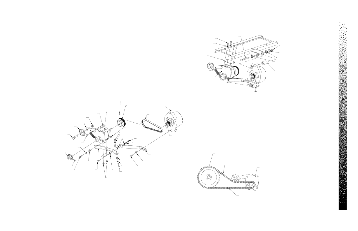
4 X 22028
4 X 22027
Transmission Pad
20808
Transmission Assembly
23591
22163
(22191)
2 X 22191
2 X 22191
22433
20114
22029
22030
Figure 10: Transmission and Alternator Assemblies
Page 71
22043
23427
2 X 22037
2 X 22164
20007
(22038)
20693
(22036)
(22036)
22042
10059
2 X 22435
2 X 22026
Transmission Assembly
Transmission
20001
20547
22139
(22037)
22983
Frame
(22435)
4 X 22036
(22036)
(22038)
(22164)
Transmission Pulley
24662
20202
(22038)
(22036)
4 X 22038
10860
22075
22146
Alternator
20205
Poly- V P u lle y
21247
Transmission Assembly Mounting to the Frame
Upper Sprocket Assembly
23424-03
Drive Chain
23257
Drive Chain Assembly
Master Link
25305
Transmission Assembly
23591
FIGURES
Page 79
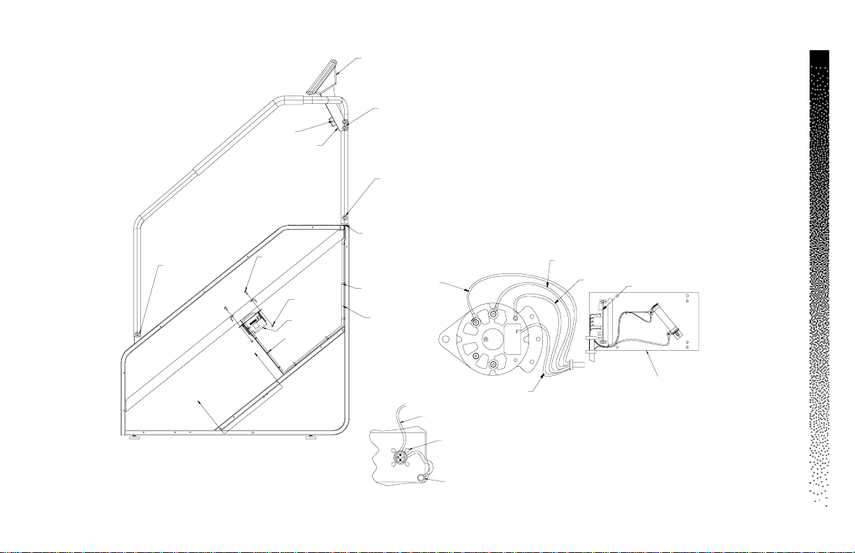
Page 72
Console
FIGURES
4 X 22323
4 x 22213
4 x 24643
2 X 24640
4 X 22213
2 X 24643
2 X 22937
2 X 21363
10794-03
4 X 22323
2 X 22323
2 X 22213
24643
22097
Grommet
15034
Tywrap
25233
Polar Cable Assy, 12”
26143
Heart Rate Cap
21765
Receiver, Polar
Plug-in
25165
®
4 X 22028
W-5
Positive
Output
4 X 22036
(22933)
4 X 20473
5 X 23792
Main Cable
21769
B
B
Power Connector
21768
W-3
Field
Console Cable
21416
Fastener, Hook
22938
Fastener, Loop
22939
Grommet
24663
Cut-Away View of Polar Receiver
W-4
AC Tap
W-6
Ground
W-5
W-4
W-3
W-2
W-1
Relay/Resistor Assembly
22933
Figure 11: Wiring Diagram
Relay Board
W-2
W-6
W-1
4 X 22663
22109
22134
Section B-B
22110
Page 80
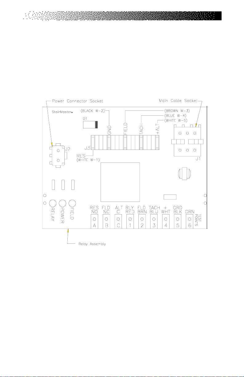
Figure 12: Relay Board
FIGURES
Page 73
 Loading...