

Stahlwille Standard Manoskop 720 Nf/80, Standard Manoskop 721 Nf/80, Service Manoskop 730/80, Standard Manoskop 721 Nf/100 Technical Description

STAHLWILLE
Torque Wrenches
Standard Manoskop
®
720 Nf/80
721 Nf/80
721 Nf/100
Service Manoskop
®
730/80
Content
Technical description . . . . . . . . . . . 25
Technical specifications. . . . . . . . . 27
ã Important safety instructions . . . 28
Operation . . . . . . . . . . . . . . . . . . . . 30
Maintenance. . . . . . . . . . . . . . . . . . 39
Cleaning the Manoskop
Accessories . . . . . . . . . . . . . . . . . . 44
Disposal . . . . . . . . . . . . . . . . . . . . . 44
®
. . . . . . . . 43
Technical
description
All models
Manoskop®720 Nf/80, 721 Nf/80,
721 Nf/100 and 730/80 are adjustable
torque wrenches with a cut-out, tactile
and audible cut-out signals.
• These torque wrenches have a
safety cut-out mechanism.
• The wrench is set to cut-out at a
certain torque level by setting the
required value on the N m/ft.lb scale
using a force-free knob.
• The setting knob has an automatic
setting fail-safe mechanism.
25

• The measuring element is a flexible
rod. The flexible rod is not
pretensioned so it is only under
tension from the start to the end of
the actual tightening operation until
the wrench cuts out.
• As soon as the torque wrench is
released, it is ready for the next job.
• These wrenches will only tighten in
one direction. To use the Manoskop
wrench for loosening, turn it over.
• If necessary, these torque wrenches
can be readjusted without
dismantling.
Maximum permissible deviation of the
set value from the absolute value at cutout is ± 4 %.
®
Manoskop
721 Nf/100 and 730/80 comply with
DIN EN ISO 6789, Type II, Class A.
Every Manoskop
number and is supplied with a works
calibration certificate.
720 Nf/80, 721 Nf/80,
®
has a unique serial
STAHLWILLE Standard
Manoskop®720 Nf/80 ...
®
... has a permanent, fixed head with an
exchangeable 20 (3/4'') square drive.
STAHLWILLE Standard
Manoskop®721 Nf/80 ...
... has a permanent, non-switchable
ratchet with an exchangeable 20 (3/4'')
square drive.
STAHLWILLE Standard
Manoskop®721 Nf/100 ...
... has a permanent, non-switchable
ratchet with an exchangeable 20 (3/4'')
square drive.
26

The wrench consists of a basic wrench
and a grip tube. The grip tube is placed
over the end of the basic wrench where it
locks in place by means of a locking pin
that locates in a hole. The locking pin is
attached to the grip tube by a springloaded ring. To attach or remove the grip
tube (e.g. for setting), press the ring
against the wall of the tube which will
extract the locking pin. The locking
position is marked with an arrow.
STAHLWILLE Service
Manoskop®730/80 ...
... can be fitted with various shell tools.
For this purpose, the head of the wrench
has an external 24.5x28 square drive
pointing forwards with a spring-loaded
locking pin on the underside. The shell
tools can be attached in the „normal“
position or rotated through 180°.
Technical
specifications
Manoskop®720 and 721
720 Nf/80 721 Nf/80 721 Nf/100
Torque range [N m]
Exchangeable square
drive [mm]
Length
Åa
Weight [g]
length to centre of square drive
a
with grip tube attached
b
160–800
[ft.lb]
120–600
fixed
20 (3/4'')
1.013 1.013 1.466
[mm]
6.135 6.770 7.570
160–800
120–600
ratchet
20 (3/4'')
200–1000
150–725
ratchet
20 (3/4'')
b
b
Manoskop®730
Torque range
[N m] [ft.lb] [mm] [g]
Model
730/80 160–800 120–600 24,5 x 28 970 4.960
shell square
drive
[mm]
Length Weight
27
Important
ã
safety
instructions
Intended Purpose
Manoskop®720 Nf/80, 721 Nf/80,
721 Nf/100 und 730/80 have been
designed for controlled tightening of
screw joints. They may only be used for
this purpose. To do so, the correct
attachments must be used with the
torque wrench.
®
Manoskop
used with the grip tube in position.
Otherwise the readings will not be
accurate.
The „intended purpose“ includes full
adherence to the information contained
in this instruction booklet, in particular the
safety instructions and technical
tolerance limits. The buyer is required to
ensure that all users comply with these
instructions.
Any use beyond the use described here
is in breach of the intended purpose.
The buyer and user are responsible for
any damage or injury resulting from nonadherence to these instructions.
• Manoskop
721 Nf/100 und 730/80 have not
been designed for tightening of
screw joints under series production
conditions. This might lead to
inaccurate readings as a result of
excessive wear in the switching
mechanism.
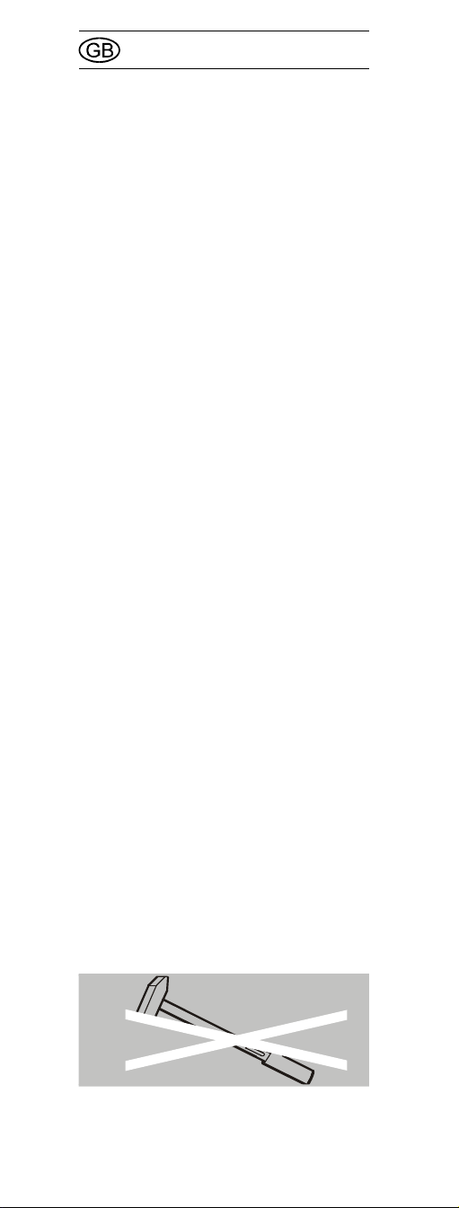
• The Manoskop
a hammer. This will lead to injury and
damage.
721 Nf/100 may only be
®
720 Nf/80, 721 Nf/80,
®
may not be used as
28

• Manoskop
721 Nf/100 und 730/80 may not be
used in the direction opposite to their
intended direction or for uncontrolled
loosening of nuts & bolts – e.g. rusty
joints. This may cause damage to the
torque wrench.
®
720 Nf/80, 721 Nf/80,
Correct torque settings ...
... can be lifesaving in some applications.
For this reason, please note the following
points:
ã CAUTION!
In order to ensure the
cut-out is working
accurately, it should be
checked at regular
intervals.
Unless otherwise indicated in the user's
internal regulations (e.g. test equipment
inspection to ISO 9000 et seq), an
inspection must take place after approx.
5000 operations or every 12 months,
whichever is the shorter. The time frame
(12 months) starts with the first usage.
If an inspection shows that there is
excessive deviation, the torque wrench
will have to be readjusted (see page 41).
Additional important safety
points ...
... may apply depending on the
application. These are found in the
appropriate sections marked with danger
symbols ã.
29
Operation
Manoskop®720 Nf/80, 721 Nf/80,
721 Nf/100 und 730/80 are measuring
instruments and must be treated with
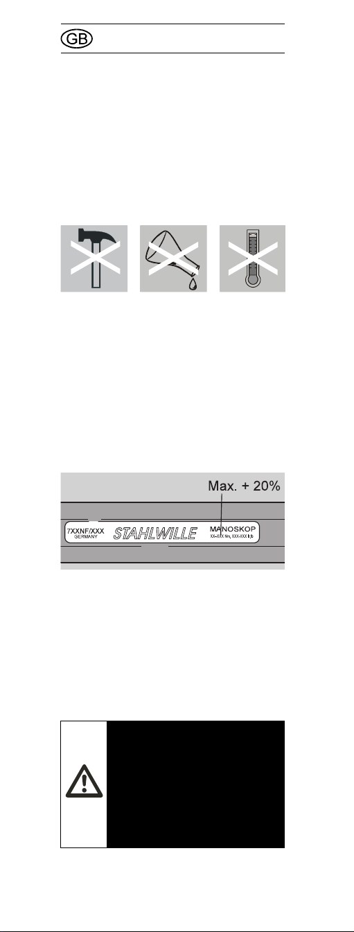
utmost care. Avoid subjecting the tool to
physical knocks, chemicals or excessive
temperatures beyond the limits given in
these instructions.
Please note that extremes of climate
(cold, heat, humidity) may affect
measuring accuracy.
Avoid overloading the tool by more than
20 % of the maximum permissible load in
the direction of tightening, as otherwise
the Manoskop
such an overload, the readings may be
inaccurate in such a way that the user
does not notice.
®
may be damaged. After
Avoid loading the tool against the
direction of tightening, as otherwise the
Manoskop
®
may be damaged.
Use the grip tube –
Manoskop®721 Nf/100
ã CAUTION!
Manoskop®721 Nf/100
may only be used with
the grip tube in position.
Otherwise the readings
will not be accurate.
30
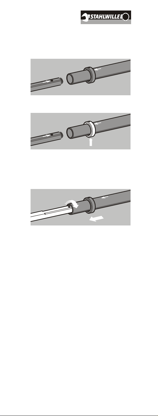
Attaching the grip tube
1. Align the arrows on the Manoskop
and the grip tube with each other.
2. Press the ring up.
®
3. Slide the grip tube over the
Manoskop
®
, until the locking pin
locates. If necessary, rotate the grip
tube slightly back and fore.
4. Check to see that the grip tube is well
located and the pin is in position.
31
 Loading...