

Page 1
USER GUIDE
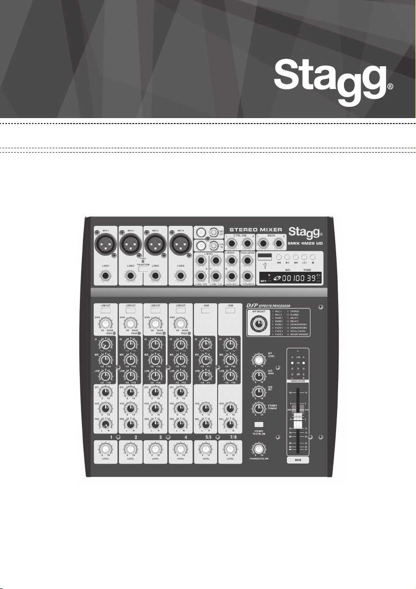
MULTI-CHANNEL STEREO MIXER
S MIX 4M2S UD
Page 2
3
FEATURES
4 mono input channels and 2 stereo input channels.
Frequency EQ on each input channel.
Low-noise mic pre-amp on microphone inputs.
Low cut lter for the mono channel.
10dB attenuator switch on stereo channel.
One AUX output channel, one AUX input channel.
Individual stereo play input and record output channel.
Stereo monitor output and headphones output channel.
+48V phantom power for condenser microphones.
Balanced main outputs L+R
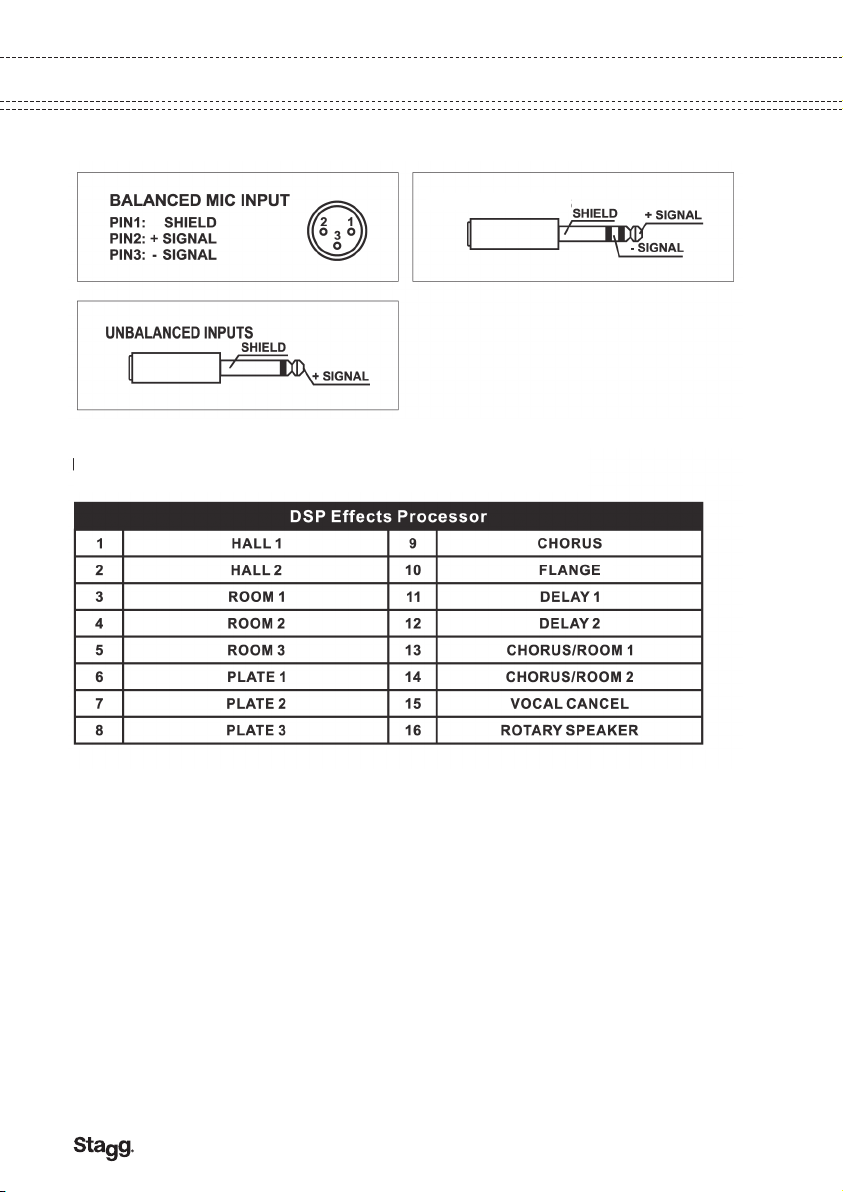
DSP effects processor, providing 16 kinds of effects.
USB interface enabling playback from a USB key source.
CONTROL PANEL
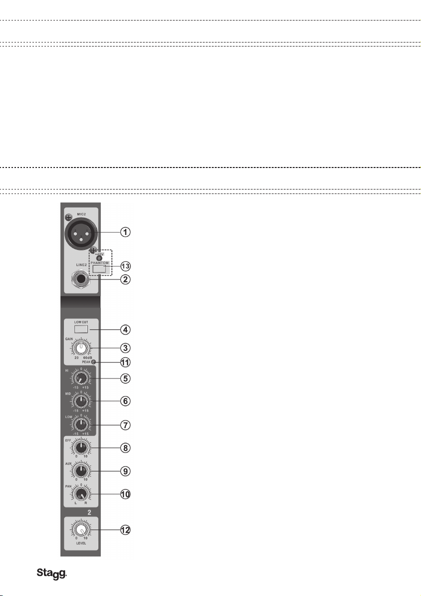
MONO CHANNEL SECTION
1. MIC. This is a balanced XLR type connector for
microphones. The input level ranges from -60 to -20dB. This
connector can provide +48V phantom power for condenser
microphones when the phantom power is switched on.
2. LINE This is a balanced 1/4” phone jack for linking a line
level source The input level ranges from -40 to 0dB.
3. GAIN Use this knob to adjust the level of the input signal
to the optimal level. For optimal S/N ratio and dynamic
range, adjust this knob so that the peak indicator lights up
occasionally.
4. LOW CUT Push down this switch to activate a low cut
lter, which allows high frequencies but attenuates low
frequencies.
5. HI This control determines the level of high frequencies in
the output signal.
6. MID This control determines the level of mid frequencies
in the output signal.
7. LOW This control determines the level of low frequencies
in the output signal.
8. EFF Use this knob to control the signal level sent from
each channel to the built-in effects processor. It is set after
the channel fader, so it is dependent on the fader position.
Adjust this knob when you use effects processor on this
channel.
9. AUX Use this knob to control the signal level sent from
each channel to the AUX bus. It is set before the channel
fader, so it is not dependent on the fader position.
10. PAN This control is used for distributing the signal level
of the channel feed to L / R buses. When the control is set to
12 o’clock, the signal is split evenly between L and R.
11. PEAK This LED signal will warn you of any excessively
high signal levels in the channel. The signal is sampled in
front of channel fader. It will light approximately 3dB before
clipping and therefore give warning of a possible overload.
12. LEVEL
This rotary fader controls the output level feed to the main
bus from the input channel.
2
Page 3

STEREO CHANNEL SECTION
13. +48V Phantom Power Switch and Indicator
This switch is used for turning on or off +48V phantom
power. +48V voltage will be present on the socket of each
microphone input channel when this switch is pressed down.
Important: set all channel faders to minimum before
turning this switch on or off. Do not plug or unplug a
microphone after this switch has been turned on. Do not
turn on the switch when a dynamic microphone is in use.
1. L/MONO - R These are two unbalanced 2-pole phone
jacks for stereo line input. The input level range is -10dB. If
the source signal is mono please use the left channel.
2. -10dB Press this switch to attenuate the line input signal
-10dB to t the high level signal source.
3. HI Use this control to raise or lower the high frequencies.
Max adjustment range: 15KHz ±15dB.
4. MID This control determines the level of mid frequencies
in the output signal.
5. LOW Use this control to raise or lower the low
frequencies. Max adjustment range: 80Hz ±15dB.
6. AUX Use this knob to control the signal level sent from
each channel to the AUX bus. It is set before the channel
fader, so it is not dependent on the fader position.
7. BAL The BAL control for the stereo channels determines
the relative volume of the left and right input signals.
8. LEVEL This rotary fader controls the output level feed to
the main bus from the input channel.
3
Page 4
5
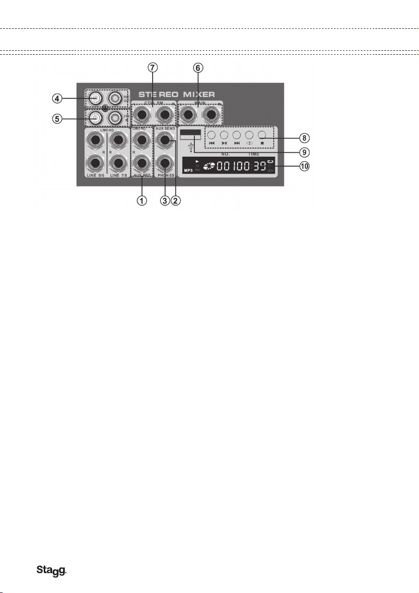
MASTER CONTROL SECTION
1. AUX RET
These two unbalanced 2-pole phone jacks are used for stereo AUX line input (the rated input level
is -10dB). If the signal source is mono please plug into the left channel socket only (L/MONO).
2. AUX SEND
This jack socket sends the signals to an auxiliary source.
3. PHONES
This jack socket sends the signals from main output or tape player to the headphones.
4. REC OUT
These two RCA sockets send stereo signals for recording purposes.
5. 2TK RET
These two RCA sockets send stereo signals from an external source.
6. MAIN
These balanced 1/4” (Ø 6.3 mm) jack outputs send line level signals from the mixer to external
devices such as an EQ unit or a power ampli er.
7. CTRL RM
These two jack sockets send stereo signals from the master output or an external player to the
control room speakers.
8. Controls for built-in player
These keys allow you operate the built-in player.
9. USB
This unit has a built-in music player. Insert in this USB port any memory stick containing songs to
be played through this device.
10. Display for built-in player
This LCD display shows the current status of the built-in player.
4
Page 5
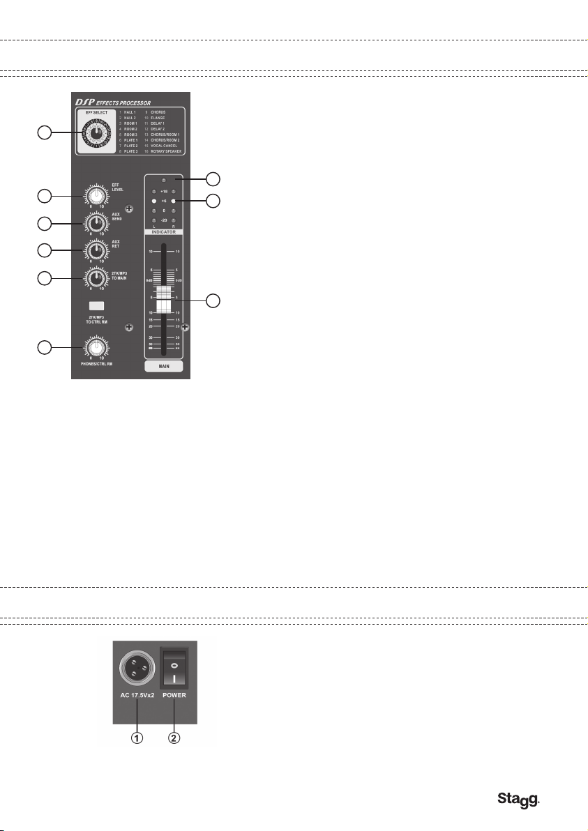
MASTER CONTROL SECTION
19
20
15
14
16
18
11. MAIN OUTPUT CONTROL
This slide fader is used for adjusting the nal output level
sent to the main output sockets.
12. Output Level Meter
This level meter Indicates the signal level of the stereo
master output.
13
13. Power Indicator
This LED indicates whether this unit is switched on or not.
12
14. AUX RET
Use this knob to control the signal level sent from AUX
return to the stereo main bus.
15. AUX SEND
Use this knob to control the signal level sent to the AUX
SEND socket.
16. 2TK/MP3 TO MIX
11
Use this knob to control the Input signal from 2TK RET
sockets or USB interface and SO card to main stereo bus.
17. 2TK/MP3 TO CTRL RM
Press this button to send the PLAY signals or the signal from
USB interface to the control room and headphones; release
this button to send the main signals to the control room and
headphones.
18. PHONES/CTRL RM
Use this knob to control the signal level of control room and
headphones.
19. EFF SELECT
Use this knob to select the effects of built-in effects
processor.
20. EFF LEVEL
Use this knob to control the effect signal level sent from
built-in effects processor to main stereo channel.
REAL PANEL SECTION
1. 17.5Vx2 AC Power Supply Socket
This AC power supply socket is used for connect the
adapter attached( do not use other adapter).
2. AC Power Switch
Use this switch to turn on/off the AC power.
5
Page 6
7
CONNECTION CABLES/EFFECTS TABLE
CONNECTION CABLES
BALANCED OU TP UT S
EFFECTS TABLE
R
6
Page 7
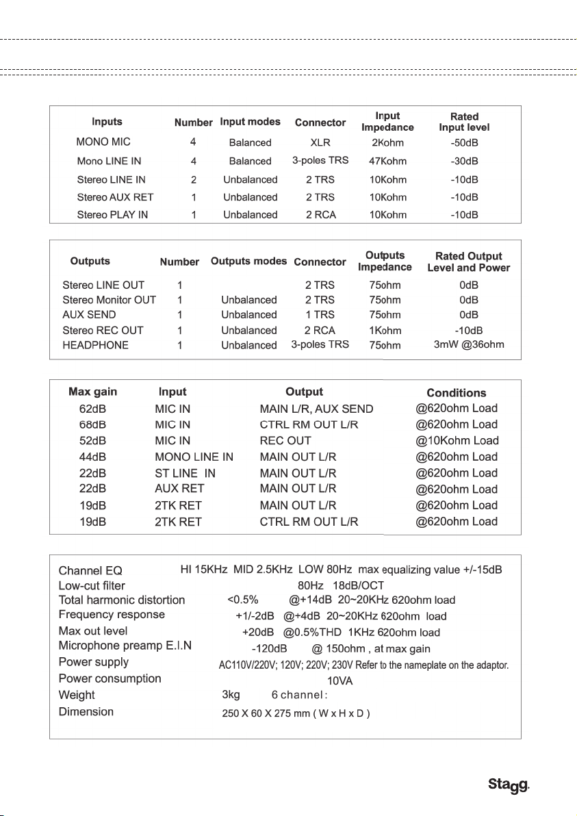
SPECIFICATIONS
Balanced
7
Page 8
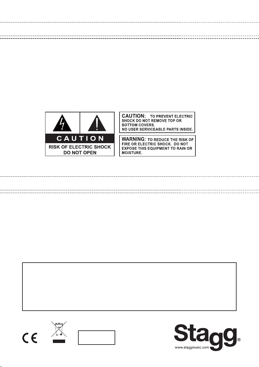
IMPORTANT SAFETY INSTRUCTIONS
READ AND KEEP THESE INSTRUCTIONS. HEED ALL WARNINGS.
• If, after you have followed the instructions outlined above, this device fails to function, please
contact your dealer. Under no circumstances should this device be opened. Leave all servicing to
qualied personnel.
• Electrical appliances must never be used in conditions of high humidity or heat.
To prevent any risk of re or electric shock, never spill or splash liquids on this device.
Should this happen, unplug the power cable from the mains outlet and switch off the mixer immediately.
• We would like to draw your intention to the instructions printed on the notice attached to the back
of the appliance.
• Exposure to extremely high noise levels may cause permanent hearing damage (especially when
using headphones). Please use this device responsibly for you and your neighbourhood.
MARKING & CONFORMITY
1. The CE mark on this product means it conforms to the EMC Directive (2004/108/CE), CE marking
Directive (93/68/EEC) and Low Voltage Directive (2006/95/EC).
2. The «Crossed-out Wheeled Bin» is to draw your attention to the WEEE (Waste Electric & Electronic
Equipment) Directive (2002/96/EC). It means this apparatus must be collected separately for recycling.
3. «RoHS compliant» means this device conforms to the Directive (2002/95EC) on the restriction of
the use of certain hazardous substances in electrical and electronic equipments, such as: Mercury,
Lead, Cadmium, Hexavalent Chromium, Polybrominated Buphenyl (PBB) and Polybrominated
Diphenyl Esthers (PBDE).
DISTRIBUTOR / DEALER
RoHS
compliant
8
EMD Music 08-2011-UK
 Loading...