

Page 1
ELECTRONICS FOR SPECIALISTS ELECTRONICS FOR SPECIALISTS ELECTRONICS FOR SPECIALISTS ELECTRONICS FOR SPECIALISTS
PARL-45SET Bestellnummer 38.6850
BEDIENUNGSANLEITUNG
INSTRUCTION MANUAL
MODE D’EMPLOI
ISTRUZIONI PER L’USO
GEBRUIKSAANWIJZING
MANUAL DE INSTRUCCIONES
INSTRUKCJA OBSŁUGI
SIKKERHEDSOPLYSNINGER
SÄKERHETSFÖRESKRIFTER
TURVALLISUUDESTA
DMX-LED-Scheinwerfer-Set
Set of DMX LED Spotlights
Page 2

2
ELECTRONICS FOR SPECIALISTS ELECTRONICS FOR SPECIALISTS ELECTRONICS FOR SPECIALISTS ELECTRONICS FOR SPECIALISTS
D Deutsch . . . . . . . . . . . . . . . Seite 4
GB English . . . . . . . . . . . . . . . Page 10
F Français . . . . . . . . . . . . . . Page 16
I Italiano . . . . . . . . . . . . . . . Pagina 22
NL Nederlands . . . . . . . . . . . . Pagina 28
E Español . . . . . . . . . . . . . . . Página 34
PL Polski . . . . . . . . . . . . . . . . Strona 40
DK Dansk . . . . . . . . . . . . . . . . Sida 46
S Svenska . . . . . . . . . . . . . . . Sidan 46
FIN Suomi . . . . . . . . . . . . . . . . Sivulta 47
Page 3

3
Page 4

4
D
A
CH
DMX-LED-Scheinwerfer-Set
Bitte lesen Sie diese Anleitung vor dem Betrieb
gründlich durch und heben Sie sie für ein späteres
Nachlesen auf. Auf der ausklappbaren Seite 3 finden Sie alle be schriebenen Bedienelemente und
Anschlüsse.
Inhalt
1 Übersicht der Bedienelemente und
Anschlüsse . . . . . . . . . . . . . . . . . . . . . . . . 4
2 Hinweise für den sicheren Gebrauch . . . 5
3 Einsatzmöglichkeiten . . . . . . . . . . . . . . . . 5
4 Inbetriebnahme . . . . . . . . . . . . . . . . . . . . . 5
4.1 Betrieb mit dem Stativ . . . . . . . . . . . . . . . . . 5
4.2 Festinstallation . . . . . . . . . . . . . . . . . . . . . . 6
4.3 Scheinwerfer ausrichten . . . . . . . . . . . . . . . 6
4.4 Stromversorgung . . . . . . . . . . . . . . . . . . . . . 6
5 Bedienung . . . . . . . . . . . . . . . . . . . . . . . . . 6
5.1 Eigenständiger Betrieb . . . . . . . . . . . . . . . . 6
5.1.1 Farbstrahler und Stroboskop . . . . . . . . . . 6
5.1.2 Farbwechsel- und Lauflichtprogramme . . 6
5.1.3 Musiksteuerung . . . . . . . . . . . . . . . . . . . . 7
5.1.4 Fußfernsteuerung . . . . . . . . . . . . . . . . . . 7
5.1.5 Master/ Slave-Betrieb . . . . . . . . . . . . . . . 7
5.2 DMX-Steuerung . . . . . . . . . . . . . . . . . . . . . 7
5.2.1 Anschluss . . . . . . . . . . . . . . . . . . . . . . . . 8
5.2.2 Anzahl der DMX-Kanäle und
Startadresse einstellen . . . . . . . . . . . . . . 8
6 Technische Daten . . . . . . . . . . . . . . . . . . . 8
6.1 DMX-Funktionen im 15-Kanal-Betrieb . . . . 9
6.2 Menüstruktur . . . . . . . . . . . . . . . . . . . . . . . . 9
1 Übersicht der Bedienelemente
und Anschlüsse
1 Montage- und Feststellschraube jeweils für
einen Scheinwerfer
Auf der Oberseite der Steuereinheit befinden
sich zusätzliche Gewindelöcher; bei Bedarf die
Schrauben herausdrehen und die Scheinwerfer
dort befestigen.
2 Feststellschrauben für die vertikale Neigung
des Scheinwerfers
3 Halterung für die Netzsicherung
Eine geschmolzene Sicherung nur durch eine
gleichen Typs ersetzen.
4 Netzbuchse zum Anschluss an eine Steckdose
(230 V~ / 50 Hz) über das beiliegende Netzkabel
5 Anschluss POWER OUT zur Stromversorgung
eines weiteren Gerätes
6 Regler SENSITIVITY zum Einstellen der Mikro-
fonempfindlichkeit für musikgesteuerte Licht effekte
7 Mikrofon für musikgesteuerte Lichteffekte
8 XLR-Einbaustecker DMX IN: DMX-Signalein-
gang zum Anschluss eines Lichtsteuergerätes
oder an den DMX-Signalausgang eines anderen DMX-gesteuerten Gerätes
9 XLR-Buchse DMX OUT: DMX-Signalausgang
zum Anschluss an den DMX-Eingang eines weiteren DMX-gesteuerten Gerätes
10 Anschluss für die beiliegende Fernbedienung (13)
11 Display
12 Bedientasten
Taste MENU zur Wahl der Betriebsart
Tasten UP und DOWN zum Ändern einer Ein-
stellung
Taste ENTER zum Aufrufen der Einstellmöglich-
keiten und zum Speichern einer Einstellung
13 Fernbedienung mit zwei Fußtasten
Taste PROGRAMS zur Wahl eines der 12 automatisch ablaufenden Lichtprogramme oder einer
der 7 Leuchtfarben
Taste BLACKOUT zum Aus- und Wiedereinschalten des Lichtes
Page 5
5
D
A
CH
2 Hinweise für den
sicheren Gebrauch
Das Gerät entspricht allen relevanten Richtlinien
der EU und ist deshalb mit gekennzeichnet.
Beachten Sie auch unbedingt folgende Punkte:
G
Verwenden Sie das Gerät nur im Innenbereich
und schützen Sie es vor Tropf- und Spritzwasser,
hoher Luftfeuchtigkeit und Hitze (zulässiger Einsatztemperaturbereich 0 – 40 °C).
G
Stellen Sie keine mit Flüssigkeit gefüllten Ge fäße, z. B. Trinkgläser, auf das Gerät.
G
Nehmen Sie das Gerät nicht in Betrieb oder zie hen Sie sofort den Netzstecker aus der Steckdose,
1. wenn sichtbare Schäden am Gerät oder am
Netzkabel vorhanden sind,
2. wenn nach einem Sturz oder Ähnlichem der
Verdacht auf einen Defekt besteht,
3. wenn Funktionsstörungen auftreten.
Geben Sie das Gerät in jedem Fall zur Reparatur
in eine Fachwerkstatt.
G
Ziehen Sie den Netzstecker nie am Kabel aus
der Steckdose, fassen Sie immer am Stecker an.
G
Verwenden Sie für die Reinigung nur ein trockenes, weiches Tuch, niemals Wasser oder Chemikalien.
G
Wird das Gerät zweckentfremdet, nicht sicher
montiert, nicht richtig angeschlossen, falsch
bedient oder nicht fachgerecht repariert, kann
keine Haftung für daraus resultierende Sachoder Personenschäden und keine Garantie für
das Gerät übernommen werden.
3 Einsatzmöglichkeiten
Das Scheinwerferset PARL-45SET besteht aus
vier flachen LED-Scheinwerfern, montiert an einer
Steuereinheit. Es dient zur Effektbeleuchtung, z. B.
auf Bühnen, in Diskotheken und Festsälen. In
jedem Scheinwerfer sind als Lichtquelle drei superhelle RGB-LEDs eingesetzt. Mit den LEDs kann
farbiges Licht in den drei Grundfarben (Rot, Grün
und Blau) und deren Mischfarben abgestrahlt
werden.
Ein Set lässt sich allein, mit der beiliegenden
Fußfernbedienung oder an einem DMX-Lichtsteuergerät (3 oder 15 DMX-Steuerkanäle) betreiben.
Zudem lassen sich mehrere Scheinwerfersets zu sammenschalten (Master / Slave-Betrieb) und ge meinsam über eine Fußfernbedienung steuern. Es
stehen verschiedene Lichtprogramme zur Verfügung. Das integrierte Mikrofon sorgt dabei für
musiksynchrone Effekte.
Zum Lieferumfang gehören ein Stativ und zwei
Transporttaschen für den mobilen Betrieb sowie
zwei Montagewinkel für eine Festinstallation.
4 Inbetriebnahme
4.1 Betrieb mit dem Stativ
1) Das Stativ auf einen waagerechten, festen
Untergrund stellen. Für einen sicheren Stand
die Stativbeine maximal spreizen und mit der
Feststellschraube fixieren.
2) Die Steuereinheit mit den Scheinwerfern auf
das Stativrohr (a) setzen und mit einer der beiliegenden Schrauben (b) fixieren (Abb. 3).
3) Zum Einstellen der gewünschten Betriebshöhe
das Teleskoprohr herausziehen. Den Sicherungsstift durch die beiden Löcher für die
gewünschte Höhe stecken und das Rohr soweit
wieder hineinschieben, dass der Sicherungsstift
auf dem Außenrohr aufliegt. Das Teleskoprohr
zusätzlich mit der Feststellschraube fixieren.
WICHTIG!
G
Das Stativ muss standsicher aufgestellt werden.
Das Teleskoprohr nur so hoch ausziehen, wie ein
sicherer Halt gewährleistet ist.
G
Vor dem Betrieb alle Feststellschrauben überprüfen und ggf. festziehen.
G
Alle Anschlusskabel so verlegen, dass niemand
darüber stolpern kann und dadurch das Stativ
umfällt.
WARNUNG Das Gerät wird mit lebensgefährli-
cher Netzspannung versorgt. Nehmen Sie deshalb niemals selbst Eingriffe am Gerät vor! Es besteht die
Gefahr eines elektrischen Schlages.
Soll das Gerät endgültig aus dem Betrieb
genommen werden, übergeben Sie es zur
umweltgerechten Entsorgung einem örtlichen Recyclingbetrieb.
Page 6

6
D
A
CH
4.2 Festinstallation
Für eine Festinstallation an einer Wand oder Decke
die beiden Montagewinkel (c) fachgerecht an ge eigneter Stelle befestigen. Die Steuereinheit mit
den beiliegenden Griffschrauben (d) an den Winkeln festschrauben (Abb. 4).
4.3 Scheinwerfer ausrichten
Zum Ausrichten der Scheinwerfer die jeweiligen
Feststellschrauben (1 und 2) lösen und den
Scheinwerfer in die gewünschte Richtung drehen
und neigen. Dabei darauf achten, dass die Kabel
nicht gedehnt oder gequetscht werden. Die Schrauben anschließend wieder festdrehen.
Auf der Oberseite der Steuereinheit befinden
sich zusätzliche Gewindelöcher, um die Scheinwerfer auch dort montieren zu können. Dazu die
Schrauben (1) der Scheinwerfer herausdrehen und
die Scheinwerfer in gleicher Art mit den Schrauben
und Gummischeiben auf der Oberseite befestigen.
4.4 Stromversorgung
Das Scheinwerferset über die Netzbuchse (4) mit
dem beiliegenden Netzkabel an eine Steckdose
(230 V~ / 50 Hz) anschließen. Das Gerät ist damit
eingeschaltet. Das Display (11) zeigt den zuletzt
gewählten Betriebsmodus an und erlischt nach
30 s. Zur Betriebsanzeige leuchtet dann nur ein
Punkt. Sobald eine Bedientaste (12) gedrückt wird,
leuchtet das Display wieder für 30 s.
Werden mehrere PARL-45SET verwendet, kann
die Buchse POWER OUT (5) des ersten Gerätes
über ein Netzkabel mit einem Kaltgerätestecker und
einer Kaltgerätekupplung (z. B. AAC-170/SW aus
dem Sortiment von MONACOR) mit der Netzbuchse (4) des zweiten Gerätes verbunden werden.
Das zweite Gerät kann dann wieder mit dem dritten
Gerät verbunden werden usw., bis alle Ge räte in
einer Kette angeschlossen sind. Auf diese Weise
lassen sich maximal 20 Geräte zusammenschalten.
Die Buchse POWER OUT kann auch zur Stromversorgung anderer (Lichteffekt-) Geräte genutzt
werden. Jedoch dürfen die Buchsen POWER IN
und POWER OUT nicht mit einem Strom von mehr
als 6,3 A belastet werden. Es kann sonst durch die
Überlastung ein Kurzschluss und Brand verursacht
werden. Die Sicherung (3) sichert diese Buchsen
nicht ab.
5 Bedienung
Die Bedientasten MENU, UP, DOWN und ENTER
(12) dienen zum Auswählen des Betriebsmodus
und verschiedener Funktionen. Die Menüstruktur
auf der Seite 9 zeigt, wie die Modi und Funktionen
angewählt werden.
5.1 Eigenständiger Betrieb
5.1.1 Farbstrahler und Stroboskop
In diesem Modus strahlen die Scheinwerfer konstant in einer einstellbaren Farbe. Zusätzlich lässt
sich die Stroboskop-Funktion einschalten.
1) Die Taste MENU so oft drücken, bis das Display
anzeigt.
2) Die Taste ENTER drücken. Das Display zeigt
für die Farbe Rot an und deren Helligkeitswert
zwischen 00 und 08.
3) Mit den Tasten UP und DOWN die gewünschte
Helligkeit für die Farbe Rot einstellen.
4) Durch mehrfaches Drücken der Taste ENTER
lassen sich nacheinander auch die Farben
Grün ( ), Blau ( ) und die Stroboskop-Funktion ( ) anwählen. Danach beginnt der Anwählzyklus wieder mit , usw. Für jede Farbe
die Helligkeit einstellen und ggf. auch die Stroboskopfrequenz ( = kein Stroboskop,
= langsam … = schnell).
Tipp: Beim Einstellen der Helligkeit der Farben Rot,
Grün und Blau ändert sich nicht nur deren Helligkeit, sondern bei einer Farbmischung auch der Farbton. Darum
zuerst die Farbe, die dominieren soll, auf die gewünschte
Helligkeit einstellen und danach die anderen beiden Farben dazumischen. Soll die Farbmischung Weiß ergeben,
zuerst die Helligkeit der Farbe Grün einstellen, weil diese
dem Auge am hellsten erscheint. Dann mit Rot zu Gelb
mischen und zuletzt mit Blau zu Weiß mischen.
5) Zum Speichern der Einstellung die Taste ENTER
so oft drücken, bis das Display anzeigt.
5.1.2 Farbwechsel- und Lauflichtprogramme
Das Gerät verfügt über 12 automatisch ablaufende
Lichtprogramme mit einstellbarer Geschwindigkeit:
1) Die Taste MENU so oft drücken, bis das Display
und eine Zahl zwischen 01 und 12 anzeigt.
Die Zahl zeigt die Programmnummer an.
2) Mit den Tasten UP und DOWN ein Lichtpro-
gramm auswählen.
3) Um die Geschwindigkeit zu ändern, die Taste
ENTER so oft drücken, bis das Display und
eine Zahl zwischen 00 und 08 anzeigt. Mit den
Tasten UP und DOWN die Geschwindigkeit einstellen. Bei der Einstellung ist das Scheinwerferlicht ausgeschaltet.
WARNUNG Blicken Sie nicht für längere Zeit
direkt in die Lichtquelle, das kann zu
Augenschäden führen.
Beachten Sie, dass sehr schnelle
Lichtwechsel bei fotosensiblen Menschen und Epileptikern epileptische
Anfälle aus lösen können!
Page 7
4) Zum Speichern der Einstellung die Taste ENTER
so oft drücken, bis das Display und die Programmnummer anzeigt.
5.1.3 Musiksteuerung
Die Scheinwerfer können durch das Mikrofon (7)
musikgesteuert werden. Dazu lassen sich vier verschiedene Steuerprogramme auswählen:
1) Die Taste MENU so oft drücken, bis das Display
anzeigt.
2) Die Taste ENTER drücken: Der zuletzt eingestellte Musikmodus ist aktiviert und wird im Display angezeigt. Mit der Taste UP oder DOWN
aus den vier Modi den gewünschten auswählen:
= Farbwechsel Rot, Grün, Blau, Gelb,
Türkis, Violett, Weiß, Rot …
= Farbwechsel Rot, Grün, Blau, Rot …
= Lauflicht
= Aufleuchten nur in Weiß
3) Zum Speichern der Einstellung die Taste ENTER
drücken, sodass das Display anzeigt.
4) Den Regler SENSITIVITY (6) für die Empfindlichkeit des Mikrofons (7) so weit im Uhrzeigersinn aufdrehen, bis die Scheinwerfer wie
gewünscht auf die Musik reagieren. Beim
Ändern der Lautstärke an der Musikanlage
muss auch die Mikrofonempfindlichkeit entsprechend angepasst werden. Sollte die Musiksteuerung trotz weit aufgedrehten Empfindlichkeitsreglers nicht optimal funktionieren, die
Lautstärke erhöhen oder den Abstand zwischen
Schallquelle und Mikrofon verringern.
5.1.4 Fußfernsteuerung
Über die mitgelieferte Fußfernbedienung (13) können die 12 Lichtprogramme angewählt werden
sowie 7 verschiedene Leuchtfarben.
1) Den Stecker der Fernbedienung in die Buchse
(10) an der Steuereinheit stecken. Die Steckverbindung durch Festdrehen der Überwurfmutter sichern.
2) Mit der Taste PROGRAMS werden zuerst nacheinander die 7 verschiedenen Leuchtfarben in
maximaler Helligkeit angewählt. Das Display
zeigt dabei an.
3) Durch weiteres Drücken der Taste PROGRAMS
folgen nacheinander die 12 Lichtprogramme
(Anzeige … ). Danach wird angezeigt und die Programme wechseln automatisch. Durch erneutes Drücken beginnt der An wählzyklus wieder mit .
4) Mit der Taste BLACKOUT lässt sich das Licht
ausschalten (Anzeige ). Zum Wiederein-
schalten die Taste BLACKOUT erneut betätigen
oder mit der Taste PROGRAMS auf das nächste
Lichtprogramm schalten.
5.1.5 Master/ Slave-Betrieb
Mehrere Geräte PARL-45SET können synchron
betrieben werden. Dabei übernimmt ein Gerät
(Master-Gerät) die Steuerung der übrigen Geräte
(Slave-Geräte). Die Geräte miteinander zu einer
Kette verbinden. Siehe dazu Kapitel 5.2.1, jedoch
ohne den Bedienschritt 1 zu beachten.
1) Alle Slave-Geräte auf Slave-Betrieb einstellen:
a) Die Taste MENU so oft drücken, bis das Dis-
play und eine Zahl zwischen 001 und 512
anzeigt.
b) Die Taste ENTER drücken, sodass rechts
neben dem ein Punkt aufleuchtet.
c) Mit der Taste UP oder DOWN die Zahl 001
einstellen.
d) Mit der Taste ENTER die Einstellung spei-
chern. Der Punkt erlischt. Wenn das SlaveGerät jedoch Steuersignale vom MasterGerät empfängt, blinkt der Punkt schnell.
2) Am Master-Gerät den gewünschte Betriebs modus einstellen (
Kapitel 5.1.1 – 5.1.3).
3) Am Master-Gerät kann auch die Fußfernbedienung angeschlossen werden (
Kapitel 5.1.4),
um alle Slave-Geräte mit dem Master-Gerät
synchron zu steuern.
5.2 DMX-Steuerung
DMX ist die Abkürzung für Digital Multiplex und
ermöglicht die digitale Steuerung von mehreren
DMX-Geräten über eine gemeinsame Steuerleitung. Zur Bedienung über ein DMX-Lichtsteuergerät
verfügt das Scheinwerferset über 15 DMX-Steuerkanäle. Es lässt sich bei Bedarf aber auch über nur
3 Kanäle steuern. Für den 15-Kanal-Betrieb sind die
Funktionen der Kanäle und die entsprechenden
DMX-Werte im Kapitel 6.1 angegeben.
Für den DMX-Betrieb des PARL-45SET sind fol-
gende Geräte von „img Stage Line“ geeignet:
Modell
Anzahl der
DMX-Kanäle
Bemerkung
DMX-1USB 510
Computer-Software
mit DMX-Konverter
DMX-510USB 510
Computer-Software
mit DMX-Konverter
DMX-3216 512 DMX-Steuerpult
DMX-4840 484 DMX-Steuerpult
LC-8DMX 8
ab Startkanal 368;
PARL-45SET im 3-Kanal-
Modus betreiben
LC-8LED 128
steuerbar im
„Record“-Modus
7
D
A
CH
Page 8
5.2.1 Anschluss
Für die DMX-Verbindung sind 3-polige XLR-An schlüsse mit folgender Kontaktbelegung vorhanden:
Pin 1 = Masse, 2 = DMX-, 3 = DMX+
Zum Anschluss sollten spezielle Kabel für die DMX-
Signalübertragung verwendet werden (z. B. Kabel
der CDMXN-Serie von „img Stage Line“). Bei Leitungslängen ab 150 m wird grundsätzlich das Zwischenschalten eines DMX-Aufholverstärkers empfohlen (z. B. SR-103DMX von „img Stage Line“).
1) Den Eingang DMX IN (8) mit dem DMX-Ausgang des Lichtsteuergerätes oder eines anderen DMX-gesteuerten Gerätes verbinden.
Falls die Fußfernbedienung (13) angeschlossen ist, diese von der Steuereinheit trennen,
damit sie die DMX-Steuerung nicht stört.
2) Den Ausgang DMX OUT (9) mit dem DMX-Eingang des nächsten DMX-Gerätes verbinden.
Dessen Ausgang wieder mit dem Eingang des
nachfolgenden DMX-Gerätes verbinden usw.,
bis alle DMX-gesteuerten Geräte in einer Kette
angeschlossen sind.
3) Um Störungen bei der Signalübertragung auszuschließen, sollte bei langen Leitungen bzw.
bei einer Vielzahl von hintereinandergeschalteten Geräten der DMX-Ausgang des letzten
DMX-Gerätes der Kette mit einem 120-ΩWiderstand (> 0,3 W) abgeschlossen werden:
In die DMX-Ausgangsbuchse einen entsprechenden Abschlussstecker (z.B. DLT-123 von
„img Stage Line“) stecken.
5.2.2 Anzahl der DMX-Kanäle und
Startadresse einstellen
Die Anzahl der DMX-Kanäle hängt von den benötigten Funktionen ab und eventuell auch von der
Anzahl der verfügbaren Steuerkanäle am Lichtsteuergerät. Im 15-Kanal-Betrieb lassen sich die
vier Scheinwerfer für eine Farbmischung getrennt
steuern, während im 3-Kanal-Betrieb nur eine
gemeinsame Steuerung möglich ist und außerdem
die Startadresse fest auf 001 einstellt ist.
1) Zum Betrieb mit 3 DMX-Kanälen die Taste
MENU so oft drücken, bis das Display an zeigt. Die Helligkeit der Farben lässt sich jetzt
ausschließlich über folgende DMX-Adressen
einstellen:
001 Helligkeit Rot
002 Helligkeit Grün
003 Helligkeit Blau
2) Zum Betrieb mit 15 DMX-Kanälen die Taste
MENU so oft drücken, bis das Display und
eine Zahl zwischen 001 und 512 anzeigt.
3) Die Taste ENTER drücken, sodass rechts
neben dem ein Punkt aufleuchtet.
4) Mit der Taste UP oder DOWN die DMX-Startadresse für den 1. DMX-Kanal einstellen und
abschließend die Taste ENTER drücken.
Um alle am Lichtsteuergerät angeschlossenen DMX-Geräte separat bedienen zu können,
muss jedes Gerät eine eigene Startadresse
erhalten. Soll der erste DMX-Kanal des PARL45SET vom Lichtsteuergerät z. B. über die
DMX-Adresse 4 gesteuert werden, am PARL45SET die Startadresse 4 einstellen. Die weiteren 14 DMX-Kanäle des PARL-45SET sind
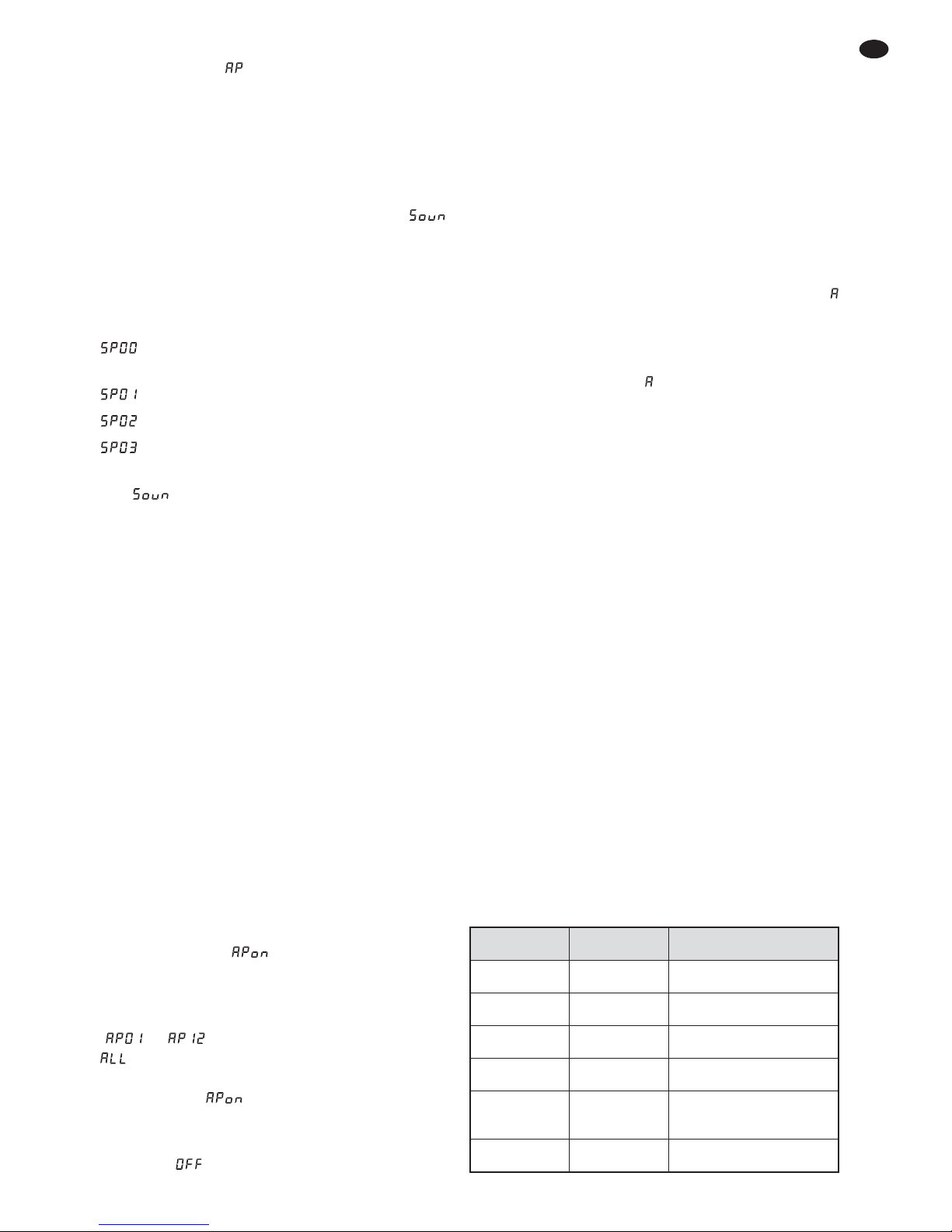
dann automatisch den darauffolgenden Adressen zugeordnet. Beispiele mit verschiedenen
Startadressen:
DMX-Adressenbelegung des PARL-45SET
5) Nach dem Einstellen der Startadresse lassen
sich die Scheinwerfer über das DMX-Steuergerät bedienen (DMX-Funktionen siehe nebenstehende Tabelle im Kapitel 6.1). Der Empfang von
DMX-Steuersignalen wird im Display durch den
blinkenden Punkt rechts neben dem angezeigt.
6 Technische Daten
Datenprotokoll: . . . . . . . . . DMX 512
Anzahl der DMX-Kanäle: . 3 oder 15
Lichtquelle: . . . . . . . . . . . . 3 RGB-LEDs je
Scheinwerfer
Leistung je LED: . . . . . . 9 W
Abstrahlwinkel: . . . . . . . 15°
Stromversorgung: . . . . . . . 230 V~ / 50 Hz
Leistungsaufnahme: . . . . . max. 55 VA
Einsatztemperatur: . . . . . . 0 –40 °C
Abmessungen: . . . . . . . . . 900 × 240 × 50 mm
(Steuereinheit mit
Scheinwerfern)
Stativhöhe: . . . . . . . . . . . . 1,25 – 2,1 m,
6-stufig einstellbar
Gewicht: . . . . . . . . . . . . . . 8,7 kg
Start-
adresse
Adressen
für das
PARL-45SET
nächstmögliche Start-
adresse für das
nachfolgende DMX-Gerät
1 1– 15 16
4 4– 18 19
12 12 – 26 27
20 20 – 34 35
8
D
A
CH
Page 9

MENU MENU
DOWN
UP
ENTER
2x
MENU
MENU
MENU
MENU
ENTER
ENTER
ENTER
ENTER
ENTER
DOWN
UP
DOWN
UP
DOWN
UP
DOWN
UP
DOWN
UP
DOWN
UP
ENTER
ENTER
DOWN
UP
ENTER
ENTER
ENTER
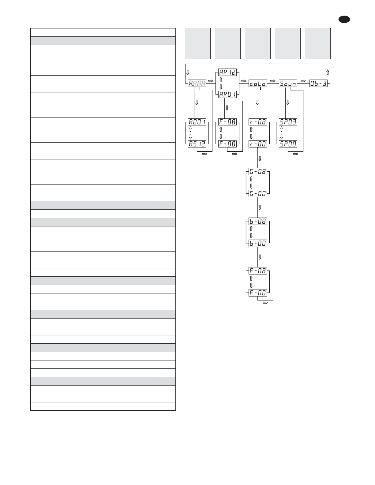
6.1 DMX-Funktionen im 15-Kanal-Betrieb 6.2 Menüstruktur
9
D
A
CH
DMX-Wert Funktion
Kanal 1: Betriebsmodus
000 – 009
Farbstrahlerbetrieb über die Kanäle
4 – 15; Dimmer- und Stroboskop-Funktion
über die Kanäle 2 und 3 einstellbar
010 – 029 Programm 1*
030 – 049 Programm 2*
050 – 069 Programm 3*
070 – 089 Programm 4*
090 – 109 Programm 5*
110 – 129 Programm 6*
130 – 149 Programm 7*
150 – 169 Programm 8*
170 – 189 Programm 9*
190 – 209 Programm 10*
210 – 229 Programm 11*
230 – 249 Programm 12*
250 – 251 Musiksteuerung SP00 (Kap. 5.1.3)
252 Musiksteuerung SP01
253 Musiksteuerung SP02
254 – 255 Musiksteuerung SP03
Kanal 2: Dimmer, nur wenn Kanal 1 = 000– 009
000 – 255 Helligkeit 0 – 100%
Kanal 3: Stroboskop, Geschwindigkeit
wenn Kanal 1 = 000 – 009:
000 – 015 kein Stroboskop
016 – 255
Stroboskop: langsam →schnell
wenn Kanal 1 = 010 – 249:
000 – 015 Scheinwerfer dunkel geschaltet
016 – 255
Programmablauf: langsam →schnell
1. Scheinwerfer: Farbmischung, wenn Kanal 1 = 000 – 009
K. 4: 000 – 255 Helligkeit Rot
K. 5: 000 – 255 Helligkeit Grün
K. 6: 000 – 255 Helligkeit Blau
2. Scheinwerfer: Farbmischung, wenn Kanal 1 = 000 – 009
K. 7: 000 – 255 Helligkeit Rot
K. 8: 000 – 255 Helligkeit Grün
K. 9: 000 – 255 Helligkeit Blau
3. Scheinwerfer: Farbmischung, wenn Kanal 1 = 000 – 009
K. 10: 000 – 255 Helligkeit Rot
K. 11: 000 – 255 Helligkeit Grün
K. 12: 000 – 255 Helligkeit Blau
4. Scheinwerfer: Farbmischung, wenn Kanal 1 = 000 – 009
K. 13: 000 – 255 Helligkeit Rot
K. 14: 000 – 255 Helligkeit Grün
K. 15: 000 – 255 Helligkeit Blau
* Der DMX-Wert des Kanals 3 muss auf größer als 15 ein -
gestellt sein, anderenfalls sind die Scheinwerfer dunkel ge schaltet.
Diese Bedienungsanleitung ist urheberrechtlich für MONACOR®INTERNATIONAL GmbH & Co. KG ge schützt.
Eine Reproduktion für eigene kommerzielle Zwecke – auch auszugsweise – ist untersagt.
Änderungen vorbehalten.
Farbstrahler-
betrieb,
Stroboskop
Musik-
steuerung
A001 – A498
= 15-Kanal-
DMX-Betrieb
A001 =
Slave-
Betrieb
Lichtsteuer programme
3-Kanal-
DMX-Betrieb
DMX-Start-
adresse =
001
Page 10

Set of DMX LED Spotlights
Please read these operating instructions carefully
prior to operation and keep them for later reference. All operating elements and connections de scribed can be found on the fold-out page 3.
Contents
1 Operating Elements and Connections .10
2 Safety Notes . . . . . . . . . . . . . . . . . . . . . . . 11
3 Applications . . . . . . . . . . . . . . . . . . . . . . . 11
4 Setting into Operation . . . . . . . . . . . . . . . 11
4.1 Operation with the stand . . . . . . . . . . . . . . 11
4.2 Fixed installation . . . . . . . . . . . . . . . . . . . . 12
4.3 Aligning the spotlights . . . . . . . . . . . . . . . . 12
4.4 Power supply . . . . . . . . . . . . . . . . . . . . . . . 12
5 Operation . . . . . . . . . . . . . . . . . . . . . . . . . 12
5.1 Stand-alone mode
5.1.1 Colour spotlights and stroboscope . . . . 12
5.1.2 Colour change programs
and running light programs . . . . . . . . . . 12
5.1.3 Music control . . . . . . . . . . . . . . . . . . . . . 13
5.1.4 Foot remote control . . . . . . . . . . . . . . . . 13
5.1.5 Master / slave mode . . . . . . . . . . . . . . . . 13
5.2 DMX control . . . . . . . . . . . . . . . . . . . . . . . 13
5.2.1 Connection . . . . . . . . . . . . . . . . . . . . . . 13
5.2.2 Setting the number of the DMX channels
and the start address . . . . . . . . . . . . . . . 14
6 Specifications . . . . . . . . . . . . . . . . . . . . . 14
6.1 DMX functions in 15-channel mode . . . . . 15
6.2 Menu structure . . . . . . . . . . . . . . . . . . . . . 15
1 Operating Elements
and Connections
1 Mounting/setscrew, one for each spotlight
On the upper side of the controller, additional
threaded holes are available; if required,
remove the screws and fasten the spotlight
there.
2 Setscrews for vertical inclination of the spotlight
3 Support for the mains fuse
Always replace a blown fuse by one of the same
type.
4 Mains jack for connection to a socket (230 V~/
50 Hz) via the mains cable provided
5 Connection POWER OUT to provide an addi-
tional unit with power
6 Control SENSITIVITY to adjust the microphone
sensitivity for music-controlled light effects
7 Microphone for music-controlled light effects
8 XLR chassis plug DMX IN: DMX signal input for
connection of a light controller or connection to
the DMX signal output of another DMX-controlled unit
9 XLR jack DMX OUT: DMX signal output for con-
nection to the DMX input of another DMX-controlled unit
10 Connection for the remote control supplied (13)
11 Display
12 Control buttons
Button MENU to select the operating mode
Buttons UP and DOWN to change a setting
Button ENTER to call up the setting options and
to save a setting
13 Remote control with two foot switches
Switch PROGRAMS to select one of the 12
automatic light programs or one of the 7 lighting
colours
Switch BLACKOUT to switch the light off and on
10
GB
Page 11

2 Safety Notes
The unit corresponds to all relevant directives of
the EU and is therefore marked with .
Please observe the following items in any case:
G
The unit is suitable for indoor use only. Protect it
against dripping water and splash water, high air
humidity and heat (admissible ambient temperature range: 0 – 40 °C).
G
Do not place any vessel with liquid on the unit,
e. g. a drinking glass.
G
Do not operate the unit and immediately disconnect the mains plug unit from the socket
1. if the unit or the mains cable is visibly damaged,
2. if a defect might have occurred after the unit
was dropped or suffered a similar accident,
3. if malfunctions occur.
In any case the unit must be repaired by skilled
personnel.
G
Never pull the mains cable to disconnect the
mains plug from the socket, always seize the
plug.
G
For cleaning only use a dry, soft cloth; never use
water or chemicals.
G
No guarantee claims for the unit and no liability
for any resulting personal damage or material
damage will be accepted if the unit is used for
other purposes than originally intended, if it is not
correctly connected or operated, or if it is not
repaired in an expert way.
3 Applications
The spotlight set PARL-45SET consists of four flat
LED spotlights mounted to a controller. It can be
used to create effect illumination, e. g. on stage, in
discotheques or in ballrooms. Each spotlight features three super-bright RGB LEDs as a light
source. The LEDs can emit light in the three primary colours (red, green and blue) or coloured light
from additive colour mixing.
A set can be operated on its own, with the foot
remote controller supplied or by means of the DMX
controller (3 or 15 DMX control channels). In addition, it is possible to interconnect multiple spotlight
sets (master / slave mode) and to control all of them
by means of a foot remote controller. Various light
programs are available. The integrated microphone
provides effects in sync with the music.
A stand and two transport bags for mobile operation as well as two mounting brackets for fixed
installation are supplied with the unit.
4 Setting into Operation
4.1 Operation with the stand
1) Place the stand on a horizontal, solid ground.
For a safe position, spread the legs of the stand
as far as possible and fix them with the
setscrew.
2) Place the controller with the spotlights onto the
stand tube (a) and fix it with one of the screws
supplied (b) [fig. 3].
3) To adjust the operating height desired: Pull out
the telescopic tube and push the safety pin
through the two holes for the height desired,
then slide back the tube until the safety pin rests
on the outer tube. Use the setscrew to additionally fix the telescopic tube.
IMPORTANT!
G
Make sure that the stand is stable. Pull out the
telescopic tube only to such an extent that the
stand cannot fall over.
G
Prior to operation, check all setscrews and, if
necessary, tighten them.
G
Lay the connection cables in such a way that
nobody will trip over them and may overturn the
stand.
If the unit is to be put out of operation
definitively, take it to a local recycling plant
for a disposal which is not harmful to the
environment.
WARNING The power supply unit uses danger-
ous mains voltage. Leave servicing
to skilled personnel. Inexpert handling or modification may result in
electric shock.
11
GB
Page 12
4.2 Fixed installation
For fixed installation to a wall or ceiling, fasten the
two mounting brackets (c) in an appropriate way at
a suitable location. Use the knurled screws supplied (d) to fasten the controller to the brackets
(fig. 4).
4.3 Aligning the spotlights
To align the spotlights, loosen the corresponding
setscrews (1 and 2) and turn and tilt the spotlight
into the direction desired, making sure that the
cables are neither squeezed nor stretched. Then
retighten the screws.
On the upper side of the controller, additional
threaded holes are available so that the spotlights
can also be mounted there: Remove the screws (1)
of the spotlights and fasten the spotlights in the
same way on the upper side of the controller, using
the rubber washers and the screws.
4.4 Power supply
Use the mains cable supplied to connect the mains
jack (4) of the spotlight set to a mains socket
(230 V~/ 50 Hz). The unit will be switched on. The
display (11) will indicate the operating mode most
recently selected and will extinguish after 30 sec.
Then only a dot will light up to indicate that the spotlight set is switched on. When a control button (12)
is pressed, the display will light up for 30 sec. again.
If multiple spotlight sets PARL-SET45 are used,
connect the jack POWER OUT (5) of the first unit to
the mains jack (4) of the second unit by means of a
mains cable with 3-pin IEC plug and 3-pin IEC
inline jack (e. g. AAC-170 / SW from the MONACOR
product line). Then connect the second unit to the
third unit, etc. until all units are connected in a
chain. Up to 20 units may be connected in this way.
The jack POWER OUT may also be used to provide power to other (light effect) units. The current
load of the jacks POWER IN and POWER OUT,
however, must not exceed 6.3A; otherwise, overload may result in short circuit and fire. The jacks
POWER IN and POWER OUT are not protected by
the fuse (3).
5 Operation
The control buttons MENU, UP, DOWN and
ENTER (12) are used to select the operating mode
and various functions. Please refer to the menu
structure on page 15 for an overview of how to
select the modes and functions.
5.1 Stand-alone mode
5.1.1 Colour spotlights and stroboscope
In the stand-alone mode, the spotlights constantly
emit an adjustable colour. The stroboscopic function may be activated in addition.
1) Press the button MENU repeatedly until
appears on the display.
2) Press the button ENTER. The display shows
for the colour red and a value between 00 and
08 to indicate its brightness.
3) Use the buttons UP and DOWN to set the
brightness desired for the colour red.
4) Press the button ENTER repeatedly to select
the colours green ( ) and blue ( ) and the
stroboscopic function ( ) one after the other.
Then the selection cycle starts again with ,
, etc. Set the brightness for each colour and,
if required, the stroboscopic frequency ( =
no stroboscope, = slow, … = fast).
Hint: Setting the brightness of the colours red, green
and blue will not only change their brightness but also
their hue in a colour mix. Therefore, first set the colour
that is to dominate to the brightness desired and then
add the other two colours. If the intended colour mix is
white, first set the brightness of the colour green,
because green appears to be the brightest colour to the
human eye. Then add red to get yellow and finally add
blue to get white.
5) To save the setting, press the button ENTER
until appears on the display.
5.1.2 Colour change programs
and running light programs
The unit provides 12 automatic light programs with
adjustable speed:
1) Press the button MENU repeatedly until and
a number between 01 and 12 appear on the display. The number indicates the program number.
2) Use the buttons UP and DOWN to select a light
program.
3) To change the speed, press the button ENTER
repeatedly until and a number between 00
and 08 appear on the display. Use the buttons
UP and DOWN to set the speed. To switch off
the spotlight, select .
WARNING To prevent damage to your eyes,
never look directly into the light
source for a longer period of time.
Please note that fast light changes
may trigger epileptic seizures with
photosensitive persons or persons
with epilepsy!
12
GB
Page 13
4) To save the setting, press the button ENTER
repeatedly until and the program number
appear on the display.
5.1.3 Music control
The spotlights can be music-controlled by means of
the microphone (7). Four different control programs
are available:
1) Press the button MENU repeatedly until
appears on the display.
2) Press the button ENTER: The music mode most
recently set will be activated and indicated on
the display. Use the button UP or DOWN to
select one of the following modes:
= colour change red, green, blue, yellow,
turquoise, purple, white, red …
= colour change red, green, blue, red …
= running light
= white flashes only
3) To save the setting, press the button ENTER so
that appears on the display.
4) Turn the control SENSITIVITY (6) for the sensitivity of the microphone (7) clockwise until the
spotlights respond to the music as desired.
When the volume of the music system is
changed, the sensitivity of the microphone must
be adjusted accordingly. If the music control
does not operate in an optimal way even though
the sensitivity control has been set to a high
level, increase the volume or reduce the distance between the sound source and the microphone.
5.1.4 Foot remote control
Use the foot remote control (13) supplied to select
the 12 light programs and 7 different lighting
colours.
1) Connect the plug of the remote control to the
jack (10) of the controller. Tighten the lock nut to
secure the connection.
2) Press the foot switch PROGRAMS to select the
7 lighting colours one after the other at maximum brightness. will appear on the display.
3) Press the foot switch PROGRAMS again to
select the 12 light programs one after the other
( … will appear on the display). Then
will appear on the display and the programs
will change automatically. To restart the selection cycle with , press the foot switch PROGRAMS again.
4) Press the foot switch BLACKOUT to switch off
the light ( will appear on the display). To
switch on the light again, press the foot switch
BLACKOUT again, or, to go to the next light program, press the foot switch PROGRAMS.
5.1.5 Master/ slave mode
Multiple units PARL-45SET can be operated in
sync. In this mode, one unit (master unit) controls
the other units. Connect the units with each other
in a chain; please refer to chapter 5.2.1, skipping
step 1.
1) Set all slave units to the slave mode:
a) Press the button MENU repeatedly until
and a number between 001 and 512 appear
on the display.
b) Press the button ENTER so that a dot lights
up on the right of .
c) Use the button UP or DOWN to set the num-
ber to 001.
d) Press the button ENTER to save the setting.
The dot will extinguish. When the slave unit
receives control signals from the master unit,
the dot will flash rapidly.
2) At the master unit, set the desired operating
mode (
chapters 5.1.1 – 5.1.3).
3) To control all slave units in sync by means of the
master unit, connect the foot remote control to
the master unit (
chapter 5.1.4).
5.2 DMX control
DMX (Digital Multiplex) allows for digital control of
multiple DMX units by means of a common control
line. For operation via a DMX light controller, the
spotlight set is equipped with 15 DMX control channels. However, it can also be controlled by 3 channels only, if required. The functions of the channels
and the corresponding DMX values for the 15channel mode can be found in chapter 6.1.
The following units from “img Stage Line” are
suitable for DMX operation of the PARL-45SET:
Model
Number of
DMX channels
Remark
DMX-1USB 510
computer software
with DMX converter
DMX-510USB 510
computer software
with DMX converter
DMX-3216 512 DMX controller
DMX-4840 484 DMX controller
LC-8DMX 8
as of start channel 368;
operate PARL-45SET
in 3-channel mode
LC-8LED 128
controllable in
the “Record” mode
13
GB
Page 14

14
GB
5.2.1 Connection
For DMX connection, 3-pole XLR connections with
the following pin configuration are available:
pin 1 = ground, 2 = DMX
-
, 3 = DMX+
For the connection, special cables for DMX signal
transmission (e. g. cables of the CDMXN series
from “img Stage Line”) should be used. For cable
lengths exceeding 150 m, the insertion of a DMX
level matching amplifier (e. g. SR-103DMX from
“img Stage Line”) is recommended.
1) Connect the input DMX IN (8) to the DMX output of the light controller or another DMX-controlled unit.
If the foot remote control (13) is connected,
disconnect it from the controller so that it will not
interfere with the DMX control.
2) Connect the output DMX OUT (9) to the DMX
input of the next DMX unit. Connect the output
of the latter DMX unit to the input of the following unit, etc. until all DMX controlled units are
connected in a chain.
3) To prevent interference in signal transmission:
For long cables or for a great number of units
connected in series, terminate the DMX output
of the last DMX unit in the chain with a 120 Ω
resistor (> 0.3 W): Connect an appropriate terminating plug (e. g. DLT-123 from “img Stage
Line”) to the DMX output jack.
5.2.2 Setting the number of the DMX channels
and the start address
The number of DMX channels depends on the
functions required and, if applicable, also on the
number of the control channels available at the light
controller. In the 15-channel mode, four spotlights
can be separately controlled for colour mixing; in
the 3-channel mode, only a common control is supported and the start address is preset to 001 (cannot be changed).
1) To select the mode with 3 DMX channels, press
the button MENU repeatedly until appears
on the display. Then the brightness of the
colours can only be set via the following DMX
addresses:
001 brightness red
002 brightness green
003 brightness blue
2) To select the mode with 15 DMX channels,
press the button MENU repeatedly until and a
number between 001 and 512 appear on the
display.
3) Press the button ENTER so that a dot on the
right of lights up.
4) Use the button UP or DOWN to set the DMX
start address for the first DMX channel; then
press the button ENTER.
For separate control of the DMX units connected to the light controller, each unit requires
a start address of its own. Example: If the first
DMX channel of the PARL-45SET is to be controlled by DMX address 4, set the start address
on the PARL-45SET to 4. The other 14 DMX
channels of the PARL-45 SET will then be automatically assigned to the subsequent ad dresses. Examples of different start addresses:
DMX address assignment of the PARL-45SET
5) Once the start address has been set, the spotlights can be operated by means of the DMX
controller (please refer to the table in chapter
6.1 for the DMX functions). When DMX control
signals are received, the dot on the right of on
the display will start flashing.
6 Specifications
Data protocol: . . . . . . . . . DMX 512
Number of DMX channels: 3 or 15
Light source: . . . . . . . . . . . 3 RGB LEDs for each
spotlight
Power of each LED: . . . 9 W
Beam angle: . . . . . . . . . 15°
Power supply: . . . . . . . . . . 230 V~/50 Hz
Power consumption: . . . . . 55 VA max.
Ambient temperature: . . . 0 – 40 °C
Dimensions: . . . . . . . . . . . 900 × 240 × 50 mm
(controller with spot-
lights)
Height of stand: . . . . . . . . . 1.25 – 2.1m
(adjustable in 6 steps)
Weight: . . . . . . . . . . . . . . . 8.7 kg
Start
address
Addresses
for the
PARL-45SET
Next possible
start address for the
subsequent DMX unit
1 1– 15 16
4 4– 18 19
12 12 – 26 27
20 20 – 34 35
Page 15
15
GB
All rights reserved by MONACOR®INTERNATIONAL GmbH & Co. KG. No part of this instruction manual may
be reproduced in any form or by any means for any commercial use.
6.1 DMX functions in 15-channel mode 6.2 Menu structure
DMX value Function
Channel 1: operating mode
000 – 009
colour spotlight mode via channels 4 – 15;
dimmer and stroboscopic functions can
be set via channels 2 and 3
010 – 029 program 1*
030 – 049 program 2*
050 – 069 program 3*
070 – 089 program 4*
090 – 109 program 5*
110 – 129 program 6*
130 – 149 program 7*
150 – 169 program 8*
170 – 189 program 9*
190 – 209 program 10*
210 – 229 program 11*
230 – 249 program 12*
250 – 251 music control SP00 (chapter. 5.1.3)
252 music control SP01
253 music control SP02
254 – 255 music control SP03
Channel 2: dimmer, only when channel 1 = 000– 009
000 – 255 brightness 0 – 100 %
Channel 3: stroboscope, speed
when channel 1 = 000 – 009:
000 – 015 no stroboscope
016 – 255
stroboscope: slow→fast
when channel 1 = 010 – 249:
000 – 015 spotlight blacked out
016 – 255
program speed: slow→fast
Spotlight 1: colour mix when channel 1 = 000 – 009
Ch. 4: 000 – 255 brightness red
Ch. 5: 000 – 255 brightness green
Ch. 6: 000 – 255 brightness blue
Spotlight 2: colour mix when channel 1 = 000 – 009
Ch. 7: 000 – 255 brightness red
Ch. 8: 000 – 255 brightness green
Ch. 9: 000 – 255 brightness blue
Spotlight 3: colour mix when channel 1 = 000 – 009
Ch. 10: 000 – 255 brightness red
Ch. 11: 000 – 255 brightness green
Ch. 12: 000 – 255 brightness blue
Spotlight 4: colour mix when channel 1 = 000 – 009
Ch. 13: 000 – 255 brightness red
Ch. 14: 000 – 255 brightness green
Ch. 15: 000 – 255 brightness blue
* Channel 3 must be set to a DMX value greater than 15;
otherwise, the spotlights will be blacked out.
Subject to technical modification.
MENU MENU
DOWN
UP
ENTER
2x
MENU
MENU
MENU
MENU
ENTER
ENTER
ENTER
ENTER
ENTER
DOWN
UP
DOWN
UP
DOWN
UP
DOWN
UP
DOWN
UP
DOWN
UP
ENTER
ENTER
DOWN
UP
ENTER
ENTER
ENTER
Colour spot-
light mode,
stroboscope
Music
control
A001 – A498
= 15-channel
DMX mode
A001 =
slave mode
Light control
programs
3-channel
DMX mode
DMX start
address =
001
Page 16

Set de projecteurs DMX à LEDs
Veuillez lire la présente notice avec attention avant
le fonctionnement et conservez-la pour pouvoir
vous y reporter ultérieurement. Vous trouverez sur
la page 3, dépliable, les éléments et branchements
décrits.
Table des matières
1 Eléments et branchements . . . . . . . . . . 16
2 Conseils dʼutilisation et de sécurité . . . 17
3 Possibilités dʼutilisation . . . . . . . . . . . . . 17
4 Fonctionnement . . . . . . . . . . . . . . . . . . . 17
4.1 Fonctionnement avec le pied . . . . . . . . . . 17
4.2 Installation fixe . . . . . . . . . . . . . . . . . . . . . 18
4.3 Orientation des projecteurs . . . . . . . . . . . . 18
4.4 Alimentation . . . . . . . . . . . . . . . . . . . . . . . 18
5 Utilisation . . . . . . . . . . . . . . . . . . . . . . . . . 18
5.1 Fonctionnement indépendant . . . . . . . . . . 18
5.1.1 Projecteur couleur et stroboscope . . . . . 18
5.1.2 Programmes changement de couleurs
et lumière défilante . . . . . . . . . . . . . . . . 18
5.1.3 Gestion par la musique . . . . . . . . . . . . . 19
5.1.4 Télécommande pédale . . . . . . . . . . . . . 19
5.1.5 Mode Master / Slave . . . . . . . . . . . . . . . . 19
5.2 Gestion DMX . . . . . . . . . . . . . . . . . . . . . . . 19
5.2.1 Branchement . . . . . . . . . . . . . . . . . . . . . 20
5.2.2 Réglage du nombre de canaux DMX
et de lʼadresse de démarrage . . . . . . . . 20
6 Caractéristiques techniques . . . . . . . . . 20
6.1 Fonctions DMX en mode 15 canaux . . . . . 21
6.2 Structure du menu . . . . . . . . . . . . . . . . . . . 21
1 Eléments et branchements
1 Vis de montage et de réglage, respectivement
pour un projecteur
Sur la face supérieure de lʼunité de commande
se trouvent des trous filetés supplémentaires ;
si besoin, retirez les vis et fixez-y les projecteurs.
2 Vis de réglage pour lʼinclinaison verticale du
projecteur
3 Porte fusible
Tout fusible fondu doit impérativement être remplacé par un fusible de même type.
4 Prise secteur à relier, via le cordon secteur livré,
à une prise 230 V~ / 50 Hz
5 Prise POWER OUT pour alimenter un second
appareil
6 Réglage SENSITIVITY pour régler la sensibilité
du micro pour des effets de lumière gérés par la
musique
7 Microphone pour des effets de lumière gérés
par la musique
8 Prise XLR châssis mâle DMX IN : entrée signal
DMX pour brancher un contrôleur ou pour brancher à la sortie de signal DMX dʼun autre appareil géré par DMX
9 Prise XLR femelle DMX OUT : sortie signal
DMX pour brancher à lʼentrée DMX dʼun autre
appareil géré par DMX
10 Branchement pour la télécommande livrée (13)
11 Affichage
12 Touches de commande
Touche MENU pour sélectionner le mode de
fonctionnement
Touches UP et DOWN pour modifier un réglage
Touche ENTER pour appeler les possibilités de
réglage et mémoriser un réglage
13 Télécommande avec deux pédales
Pédale PROGRAMS pour sélectionner un des
12 programmes de lumière automatiques ou
une des 7 couleurs
Pédale BLACKOUT pour éteindre et rallumer la
lumière
16
F
B
CH
Page 17

2 Conseils dʼutilisation
et de sécurité
Lʼappareil répond à toutes les directives nécessaires de lʼUnion européenne et porte donc le symbole
.
Respectez scrupuleusement les points suivants :
G
Lʼappareil nʼest conçu que pour une utilisation en
intérieur. Protégez-le de tout type de projections
d'eau, des éclaboussures, d'une humidité élevée
de l'air et de la chaleur (plage de température de
fonctionnement autorisée : 0 – 40 °C).
G
En aucun cas, vous ne devez pas poser d'objet
contenant du liquide ou un verre sur l'appareil.
G
Ne faites pas fonctionner lʼappareil ou débranchez-le immédiatement du secteur lorsque :
1. des dommages visibles apparaissent sur l'appareil ou sur le cordon secteur,
2. après une chute ou un cas similaire, vous avez
un doute sur l'état de l'appareil,
3. des dysfonctionnements apparaissent.
Dans tous les cas, les dommages doivent être
réparés par un technicien spécialisé.
G
Ne débranchez jamais l'appareil en tirant sur le
cordon secteur ; retirez toujours le cordon secteur en tirant la fiche.
G
Pour le nettoyage, utilisez un chiffon sec et doux,
en aucun cas de produits chimiques ou dʼeau.
G
Nous déclinons toute responsabilité en cas de
dommages matériels ou corporels résultants si
lʼappareil est utilisé dans un but autre que celui
pour lequel il a été conçu, sʼil nʼest pas monté
dʼune manière sûre, correctement utilisé ou nʼest
pas réparé par une personne habilitée, en outre,
la garantie deviendrait caduque.
3 Possibilités dʼutilisation
Ce set de projecteurs PARL-45SET se compose de
4 projecteurs plats à LEDs, montés sur une unité
de commande. Il permet de créer des effets de
lumière par exemple sur scène, dans des discothèques ou salles des fêtes. Trois LEDs RGB très
claires sont montées dans chaque projecteur. Avec
les LEDs, on peut diffuser une lumière dans les
trois couleurs primaires (rouge, vert, bleu) et leurs
couleurs de mixage.
Un set peut être géré seul, avec la télécommande pédale livrée ou avec un contrôleur DMX
(3 ou 15 canaux DMX). On peut également brancher ensemble plusieurs sets (mode Master / Slave)
et les gérer via une télécommande pédale. Différents programmes de lumière sont disponibles. Le
microphone intégré permet dʼavoir des effets synchrones avec la musique.
Un pied, deux sacoches de transport pour une
utilisation mobile et deux étriers de montage pour
une installation fixe sont également livrés.
4 Fonctionnement
4.1 Fonctionnement avec le pied
1) Placez le pied sur une surface horizontale et
fixe. Pour une assise sûre, écartez au maximum
les pieds et serrez avec la vis de réglage.
2) Placez lʼunité de commande avec les projec-
teurs sur le tube de pied (a) et fixez avec une
des vis livrées (b) [schéma 3].
3) Pour régler la hauteur souhaitée, tirez le tube
télescopique. Mettez la goupille de sécurité
dans les deux trous pour la hauteur voulue et
poussez le tube jusquʼà ce que la goupille reste
sur le tube extérieur. Fixez ensuite le tube télescopique avec la vis de réglage.
IMPORTANT !
G
Le pied doit être positionné de manière sûre. Ne
dépliez le tube télescopique quʼà une hauteur qui
puisse garantir une bonne stabilité.
G
Avant le fonctionnement, vérifiez toutes les vis de
réglage et si besoin resserrez-les.
G
Placez tous les câbles de branchement de telle
sorte que personne ne puisse trébucher et faire
ainsi tomber le pied.
Lorsque lʼappareil est définitivement retiré
du service, vous devez le déposer dans
une usine de recyclage adaptée pour
contribuer à son élimination non polluante.
AVERTISSEMENT Lʼappareil est alimenté par une
tension dangereuse. Ne touchez
jamais l'intérieur de l'appareil et
ne faites rien tomber dans les
ouïes de ventilation ! Risque de
décharge électrique.
17
F
B
CH
Page 18

4.2 Installation fixe
Pour une installation fixe sur un mur ou au plafond,
fixez les deux étriers de montage (c) de manière
appropriée à lʼendroit voulu. Vissez lʼunité de commande avec les vis livrées (d) sur les étriers
(schéma 4).
4.3 Orientation des projecteurs
Pour orienter les projecteurs, desserrez les vis correspondantes (1 et 2), tournez le projecteur dans la
direction voulue et inclinez-le. Veillez à ce que les
câbles ne soient pas étirés ou torsadés. Revissez
ensuite.
Des trous filetés supplémentaires se trouvent
sur la face supérieure de lʼunité de commande pour
pouvoir y monter les projecteurs. Pour ce faire, retirez les vis (1) des projecteurs, fixez les projecteurs
de la même façon avec les vis et rondelles en
caoutchouc sur la face supérieure de lʼunité de
commande.
4.4 Alimentation
Reliez le set à une prise 230 V~ / 50 Hz via le cordon
secteur livré, branché à la prise secteur (4). Lʼappareil est alors allumé. Lʼaffichage (11) indique le
dernier mode de fonctionnement réglé puis sʼéteint
après 30 secondes. Seul un point brille et sert de
témoin de fonctionnement. Dès que vous appuyez
sur une touche de commande (12), lʼaffichage se
rallume pendant 30 secondes.
Si vous utilisez plusieurs PARL-45SET, vous pouvez relier la prise POWER OUT (5) du premier
appareil via un cordon secteur avec fiche IEC mâle
3 pins et fiche IEC femelle 3 pins (par exemple
AAC-170 / SW de MONACOR) à la prise secteur (4)
du deuxième appareil. Vous pouvez ensuite relier
le deuxième appareil au troisième et ainsi de suite
pour que tous les appareils forment une chaîne. On
peut relier ensemble jusquʼà 20 appareils.
La prise POWER OUT peut également être utilisée comme alimentation dʼautres appareils (jeux
de lumière). Cependant, les prises POWER IN et
POWER OUT ne devraient pas avoir un courant de
plus de 6,3 A. Sinon, la surcharge peut causer un
court-circuit et un incendie. Le fusible (3) ne protège pas ces prises.
5 Utilisation
Les touches de commandes MENU, UP, DOWN,
ENTER (12) servent pour sélectionner le mode de
fonctionnement et différentes fonctions. La structure du menu, page 21, présente la façon de sélectionner les modes et fonctions.
5.1 Fonctionnement indépendant
5.1.1 Projecteur couleur et stroboscope
Avec ce mode, les projecteurs diffusent de manière
constante une couleur réglable. En plus, on peut
activer la fonction stroboscope.
1) Appuyez sur la touche MENU jusquʼà ce que
lʼaffichage indique .
2) Appuyez sur la touche ENTER. Lʼaffichage
indique pour la couleur rouge et sa luminosité entre 00 et 08.
3) Avec les touches UP et DOWN, réglez la luminosité voulue pour le rouge.
4) Par plusieurs pressions sur la touche ENTER,
vous pouvez sélectionner les unes après les
autres les couleurs vert ( ) et bleu ( ) et la fonction stroboscope ( ). Ensuite, le cycle de sélection recommence avec , etc. Réglez,
pour chaque couleur, la luminosité et si besoin la
fréquence du stroboscope ( = aucun stroboscope, = lent … = rapide).
Conseil : lorsque vous réglez la luminosité des couleurs
rouge, vert et bleu, non seulement leur luminosité se
modifie mais aussi la teinte pour un mixage de couleur.
Cʼest pourquoi, réglez tout dʼabord la couleur qui doit
dominer sur la luminosité voulue puis mixez les deux
autres couleurs. Si le mixage de couleurs doit donner du
blanc, réglez tout dʼabord la luminosité du vert car cʼest
celle qui apparaît la plus claire aux yeux. Ensuite, mixez
avec du rouge pour avoir du jaune et avec du bleu pour
avoir du blanc.
5) Pour mémoriser le réglage, appuyez sur la
touche ENTER jusquʼà ce que lʼaffichage in dique .
5.1.2 Programmes changement de couleurs
et lumière défilante
Lʼappareil dispose de 12 programmes de lumière
automatiques avec vitesse réglable :
1) Appuyez sur la touche MENU jusquʼà ce que
lʼaffichage indique et un chiffre entre 01 et
12. Le chiffre indique le numéro du programme.
2) Avec les touches UP et DOWN, sélectionnez un
programme de lumière.
3) Pour modifier la vitesse, appuyez sur la touche
ENTER jusquʼà ce que lʼaffichage indique et
un chiffre entre 00 et 08. Avec les touches UP et
DOWN, réglez la vitesse. Avec le réglage ,
la lumière du projecteur est éteinte.
AVERTISSEMENT Ne regardez jamais directement
la source de lumière pendant
une longue période, cela pourrait
causer des troubles de la vision.
N'oubliez pas que des changements très rapides de lumière
peuvent déclencher des crises
d'épilepsie chez les personnes
photosensibles et épileptiques.
18
F
B
CH
Page 19

4) Pour mémoriser le réglage, appuyez sur la
touche ENTER jusquʼà ce que lʼaffichage in dique et le numéro du programme.
5.1.3 Gestion par la musique
Les projecteurs peuvent être gérés par le microphone (7). Quatre programmes de commande sont
sélectionnables :
1) Appuyez sur la touche MENU jusquʼà ce que
lʼaffichage indique .
2) Appuyez sur la touche ENTER : le dernier mode
de musique réglé est activé et est indiqué sur lʼaffichage. Avec la touche UP ou DOWN, sélectionnez le mode souhaité parmi les quatre modes :
= changement de couleur rouge, vert, bleu,
jaune, turquoise, violet, blanc, rouge …
= changement de couleur rouge, vert,
bleu, rouge …
= lumière défilante
= éclairage uniquement en blanc
3) Pour mémoriser le réglage, appuyez sur la
touche ENTER pour que lʼaffichage indique
.
4) Tournez le réglage SENSITIVITY (6) pour la
sensibilité du microphone (7) vers la droite
jusquʼà ce que les projecteurs réagissent
comme souhaité à la musique. Si vous modifiez
le volume sur lʼinstallation audio, il faut adapter
en conséquence la sensibilité du microphone.
Si la gestion par la musique ne devait pas fonctionner de manière optimale même si le réglage
de sensibilité est très à droite, augmentez le
volume ou diminuez la distance entre la source
audio et le microphone.
5.1.4 Télécommande pédale
Via la télécommande pédale livrée (13), vous
pouvez sélectionner 12 programmes de lumière et
7 couleurs.
1) Reliez la fiche de la télécommande à la prise
(10) sur lʼunité de commande. Verrouillez la
connexion en tournant lʼécrou.
2) Appuyez sur la pédale PROGRAMS pour sélectionner les unes après les autres les 7 couleurs
avec une luminosité maximale. Lʼaffichage in dique .
3) Appuyez sur la pédale PROGRAMS de nouveau pour sélectionner les uns après les autres
les 12 programmes de lumière (affichage
… ). Ensuite sʼaffiche, les programmes
changent automatiquement. Par une nouvelle
pression, le cycle de sélections recommence
avec .
4) Avec la pédale BLACKOUT, vous pouvez éteindre la lumière (affichage ). Pour la rallumer,
appuyez une nouvelle fois sur la touche
BLACKOUT ou passez au programme de
lumière suivant avec la pédale PROGRAMS.
5.1.5 Mode Master/ Slave
Plusieurs PARL-45SET peuvent fonctionner de
manière synchrone. Un appareil (appareil Master)
prend la gestion des autres appareils (appareils
Slave). Reliez les appareils en une chaîne. Voir
chapitre 5.2.1 mais sans tenir compte du point 1.
1) Réglez tous les appareils Slave sur le mode
Slave :
a) Appuyez sur la touche MENU jusquʼà ce
que lʼaffichage indique et un chiffre entre
001 et 512.
b) Appuyez sur la touche ENTER pour quʼun
point brille à droite du .
c) Avec la touche UP ou DOWN, réglez le chif-
fre 001.
d) Avec la touche ENTER, mémorisez le ré -
glage. Le point sʼéteint. Si lʼappareil Slave
reçoit des signaux de commande de lʼappareil Master, le point clignote rapidement.
2) Sur lʼappareil Master, réglez le mode de fonctionnement voulu (
chapitre 5.1.1 – 5.1.3).
3) Sur lʼappareil Master, on peut également brancher la télécommande pédale (
chapitre 5.1.4)
pour gérer de manière synchrone tous les appareils Slave avec lʼappareil Master.
5.2 Gestion DMX
DMX est l'abréviation de Digital Multiplex et signifie
transmission digitale de plusieurs appareils DMX
via un câble commun de commande. Pour une
gestion via un contrôleur DMX, le set de projecteurs dispose de 15 canaux de commande DMX.
Selon les besoins, il peut être géré uniquement via
3 canaux. Pour le mode 15 canaux, les fonctions
des canaux et les valeurs DMX correspondantes
sont présentés dans le chapitre 6.1.
Pour le fonctionnement DMX du PARL-45SET, les
appareils suivants de “img Stage Line” sont adaptés :
Modèle
Nombre de
canaux DMX
Remarque
DMX-1USB 510
logiciel ordinateur avec
convertisseur DMX
DMX-510USB 510
logiciel ordinateur avec
convertisseur DMX
DMX-3216 512 pupitre de commande DMX
DMX-4840 484 pupitre de commande DMX
LC-8DMX 8
à partir du canal de départ 368 ;
faire fonctionner le PARL-
45SET en mode 3 canaux
LC-8LED 128 gérable en mode “Record”
19
F
B
CH
Page 20

20
F
B
CH
5.2.1 Branchement
Pour la connexion DMX, des branchements XLR
3 pôles avec la configuration de contact suivante
sont prévus :
Pin 1 = masse, 2 = DMX
-
, 3 = DMX+
Pour le branchement, il est recommandé d'utiliser
des câbles spécifiques pour la transmission de
signaux DMX (par exemple câbles des séries
CDMXN de “img Stage Line”). Pour des longueurs
de liaison à partir de 150 m, il est recommandé d'insérer un amplificateur DMX de signal (par exemple
SR-103DMX de “img Stage Line”).
1) Reliez lʼentrée DMX IN (8) à la sortie DMX du
contrôleur ou dʼun autre appareil géré par DMX.
Si la télécommande pédale (13) est branchée,
débranchez-la de lʼunité de commande pour
éviter quʼelle ne perturbe la gestion DMX.
2) Reliez la sortie DMX OUT (9) à lʼentrée DMX du
prochain appareil DMX. Reliez sa sortie à lʼentrée de lʼappareil DMX suivant et ainsi de suite
de manière à ce que tous les appareils gérés
par DMX forment une chaîne.
3) Pour éviter les perturbations lors de la transmission du signal, il convient, pour de longs câbles
ou pour une multitude dʼappareils branchés les
uns derrière les autres, de terminer la sortie
DMX du dernier appareil DMX de la chaîne avec
une résistance 120 Ω (> 0,3 W) : mettez un bouchon (par exemple DLT-123 de “img Stage
Line”) à la prise de sortie DMX.
5.2.2 Réglage du nombre de canaux DMX
et de lʼadresse de démarrage
Le nombre de canaux DMX dépend des fonctions
nécessaires et éventuellement du nombre de
canaux de commande disponibles sur le contrôleur. En mode 15 canaux, on peut gérer séparément les quatre projecteurs pour un mixage des
couleurs ; en mode 3 canaux, seule une gestion
commune est possible, lʼadresse de démarrage est
réglée, de manière fixe, sur 001.
1) Pour le fonctionnement avec 3 canaux DMX,
appuyez sur la touche MENU jusquʼà ce que
soit visible sur lʼaffichage. Vous pouvez
régler la luminosité des couleurs exclusivement
via les adresses DMX suivantes :
001 luminosité rouge
002 luminosité vert
003 luminosité bleu
2) Pour le fonctionnement avec 15 canaux DMX,
appuyez sur la touche MENU jusquʼà ce que
et un chiffre entre 001 et 512 soit visible sur lʼaffichage.
3) Appuyez sur la touche ENTER pour quʼun point
sʼaffiche à droite du .
4) Avec la touche UP ou DOWN, réglez lʼadresse
de démarrage DMX pour le premier canal DMX
puis appuyez sur la touche ENTER.
Pour pouvoir utiliser séparément tous les
appareils DMX reliés au contrôleur, chaque
appareil doit avoir une adresse de démarrage
propre. Exemple : si le premier canal DMX du
PARL-45SET est géré par le contrôleur via
lʼadresse DMX 4, réglez sur le PARL-45SET
lʼadresse de démarrage 4. Les 14 autres canaux
DMX du PARL-45SET sont automatiquement
attribués aux adresses suivantes. Exemples
avec différentes adresses de démarrage :
Configuration des adresses DMX du PARL-45SET
5) Une fois lʼadresse de démarrage réglée, vous
pouvez utiliser les projecteurs via le contrôleur
DMX (voir tableau dans le chapitre 6.1 pour les
fonctions DMX). La réception des signaux de
commande DMX est signalée sur lʼaffichage par
un point clignotant à droite du .
6 Caractéristiques techniques
Protocole données : . . . . . DMX 512
Nombre de canaux DMX : 3 ou 15
Source de lumière : . . . . . . 3 LEDs RGB par pro-
jecteur
Puissance par LED : . . . 9 W
Angle diffusion : . . . . . . 15°
Alimentation : . . . . . . . . . . 230 V~ / 50 Hz
Consommation : . . . . . . . . max. 55 VA
Température fonc. : . . . . . . 0 – 40 °C
Dimensions : . . . . . . . . . . . 900 × 240 × 50 mm
(unité de commande
avec projecteurs)
Hauteur pied : . . . . . . . . . . 1,25 – 2,1 m,
réglable en 6 paliers
Poids : . . . . . . . . . . . . . . . . 8,7 kg
Adresse de
démarrage
Adresses
pour le
PARL-45SET
Prochaine adresse de
démarrage possible pour
lʼappareil DMX suivant
1 1– 15 16
4 4– 18 19
12 12 – 26 27
20 20 – 34 35
Page 21

21
F
B
CH
Notice dʼutilisation protégée par le copyright de MONACOR®INTERNATIONAL GmbH & Co. KG. Toute reproduction même partielle à des fins commerciales est interdite.
MENU MENU
DOWN
UP
ENTER
2x
MENU
MENU
MENU
MENU
ENTER
ENTER
ENTER
ENTER
ENTER
DOWN
UP
DOWN
UP
DOWN
UP
DOWN
UP
DOWN
UP
DOWN
UP
ENTER
ENTER
DOWN
UP
ENTER
ENTER
ENTER
6.1 Fonctions DMX en mode 15 canaux 6.2 Structure du menu
Valeur DMX Fonction
Canal 1 : mode de fonctionnement
000 – 009
fonctionnement projecteur de couleurs via
les canaux 4 — 15 ; les fonctions dimmer et
stroboscope sont réglables via les canaux
2 et 3
010 – 029 programme 1*
030 – 049 programme 2*
050 – 069 programme 3*
070 – 089 programme 4*
090 – 109 programme 5*
110 – 129 programme 6*
130 – 149 programme 7*
150 – 169 programme 8*
170 – 189 programme 9*
190 – 209 programme 10*
210 – 229 programme 11*
230 – 249 programme 12*
250 – 251 gestion par la musique SP00 (chapitre 5.1.3)
252 gestion par la musique SP01
253 gestion par la musique SP02
254 – 255 gestion par la musique SP03
Canal 2 : dimmer, uniquement si canal 1 = 000– 009
000 – 255 luminosité 0 – 100 %
Canal 3 : stroboscope, vitesse
si canal 1 = 000 – 009 :
000 – 015 aucun stroboscope
016 – 255
stroboscope : lent→rapide
si canal 1 = 010 – 249 :
000 – 015 projecteur assombri
016 – 255
défilement programmes : lent→rapide
Projecteur 1 : mixage couleur si canal 1 = 000 – 009
C. 4 : 000 – 255 luminosité rouge
C. 5 : 000 – 255 luminosité vert
C. 6 : 000 – 255 luminosité bleu
Projecteur 2 : mixage couleur si canal 1 = 000 – 009
C. 7 : 000 – 255 luminosité rouge
C. 8 : 000 – 255 luminosité vert
C. 9 : 000 – 255 luminosité bleu
Projecteur 3 : mixage couleur si canal 1 = 000 – 009
C. 10 : 000 – 255 luminosité rouge
C. 11 : 000 – 255 luminosité vert
C. 12 : 000 – 255 luminosité bleu
Projecteur 4 : mixage couleur si canal 1 = 000 – 009
C. 13 : 000 – 255 luminosité rouge
C. 14 : 000 – 255 luminosité vert
C. 15 : 000 – 255 luminosité bleu
* La valeur DMX du canal 3 doit être supérieure à 15 sinon les
projecteurs ne sont pas allumés.
Tout droit de modification réservé.
Mode
projecteur,
stroboscope
Gestion par
la musique
A001 – A498
= mode DMX
15 canaux
A001 =
mode Slave
Programmes
de lumière
Mode DMX
3 canaux
Adresse de
démarrage
DMX = 001
Page 22

Set di proiettori DMX a LED
Vi preghiamo di leggere attentamente le presenti
istruzioni prima della messa in funzione e di conservarle per un uso futuro. A pagina 3, se aperta
completamente, vedrete tutti gli elementi di co mando e i collegamenti descritti.
Indice
1 Elementi di comando e collegamenti . . 22
2 Avvertenze di sicurezza . . . . . . . . . . . . . 23
3 Possibilità d'impiego . . . . . . . . . . . . . . . 23
4 Messa in funzione . . . . . . . . . . . . . . . . . . 23
4.1 Funzionamento con stativo . . . . . . . . . . . . 23
4.2 Installazione fissa . . . . . . . . . . . . . . . . . . . 24
4.3 Orientare i proiettori . . . . . . . . . . . . . . . . . 24
4.4 Alimentazione . . . . . . . . . . . . . . . . . . . . . . 24
5 Funzionamento . . . . . . . . . . . . . . . . . . . . 24
5.1 Funzionamento autonomo . . . . . . . . . . . . 24
5.1.1 Proiettore a colori e stroboscopio . . . . . 24
5.1.2 Programmai di cambio colori
e di luci a scorrimento . . . . . . . . . . . . . . 24
5.1.3 Comando tramite la musica . . . . . . . . . . 25
5.1.4 Telecomando a pedale . . . . . . . . . . . . . 25
5.1.5 Funzionamento master / slave . . . . . . . . 25
5.2 Comando DMX . . . . . . . . . . . . . . . . . . . . . 25
5.2.1 Collegamento . . . . . . . . . . . . . . . . . . . . 26
5.2.2 Impostare il numero dei canali DMX
e l'indirizzo di start . . . . . . . . . . . . . . . . . 26
6 Dati tecnici . . . . . . . . . . . . . . . . . . . . . . . . 26
6.1 Funzioni DMX con funzionamento
a 15 canali . . . . . . . . . . . . . . . . . . . . . . . . . 27
6.2 Struttura del menù . . . . . . . . . . . . . . . . . . . 27
1 Elementi di comando
e collegamenti
1 Vite di montaggio e di bloccaggio, una per ogni
proiettore
Sul lato superiore dell'unità di comando si trovano ulteriori fori filettati; se necessario, svitare
le viti e fissare i proiettori in quei posti.
2 Viti di bloccaggio per l'inclinazione verticale del
proiettore
3 Portafusibile
Sostituire un fusibile difettoso solo con uno dello
stesso tipo.
4 Presa per il collegamento con una presa di rete
(230 V~ / 50 Hz) tramite il cavo in dotazione
5 Contatto POWER OUT per l'alimentazione di un
ulteriore apparecchio
6 Regolatore SENSITIVITY per impostare la sen-
sibilità del microfono per effetti di luce comandati dalla musica
7 Microfono per effetti di luce comandati dalla
musica
8 Connettore XLR da pannello DMX IN: ingresso
dei segnali DMX per il collegamento di un'unità
di comando luce oppure con l'uscita dei segnali
DMX di un altro apparecchio con comando
DMX
9 Presa XLR DMX OUT: uscita dei segnali DMX
per il collegamento con l'ingresso DMX di un
altro apparecchio con comando DMX
10 Contatto per il telecomando in dotazione (13)
11 Display
12 Tasti funzione
Tasto MENU per la scelta del modo di funzionamento
Tasti UP e DOWN per modificare un'impostazione
Tasto ENTER per aprire le possibilità d'impostazione e per salvare un'impostazione
13 Telecomando con due tasti a pedale
Tasto PROGRAMS per scegliere uno dei 12
programmi di luci a svolgimento automatico
oppure uno dei 7 colori luminosi
Tasto BLACKOUT per spegnere e riaccendere
la luce
22
I
Page 23

2 Avvertenze di sicurezza
Questʼapparecchio è conforme a tutte le direttive
rilevanti dellʼUE e pertanto porta la sigla
.
Si devono osservare assolutamente anche i
seguenti punti:
G
Usare lʼapparecchio solo allʼinterno di locali e proteggerlo dall'acqua gocciolante e dagli spruzzi
d'acqua, da alta umidità dell'aria e dal calore
(temperatura dʼimpiego ammessa fra 0 e 40 °C).
G
Non depositare sull'apparecchio dei contenitori
riempiti di liquidi, p. es. bicchieri.
G
Non mettere in funzione lʼapparecchio e staccare
subito la spina rete se:
1. lʼapparecchio o il cavo rete presentano dei
danni visibili;
2. dopo una caduta o dopo eventi simili sussiste
il sospetto di un difetto;
3. lʼapparecchio non funziona correttamente.
Per la riparazione rivolgersi sempre ad unʼofficina competente.
G
Staccare il cavo rete afferrando la spina, senza
tirare il cavo.
G
Per la pulizia usare solo un panno morbido,
asciutto; non impiegare in nessun caso acqua o
prodotti chimici.
G
Nel caso dʼuso improprio, di montaggio non
sicuro, di collegamenti sbagliati, dʼimpiego scorretto o di riparazione non a regola dʼarte dell'apparecchio, non si assume nessuna responsabilità per eventuali danni consequenziali a persone
o a cose e non si assume nessuna garanzia per
l'apparecchio.
3 Possibilità d'impiego
Il set di proiettori PARL-45SET è composto da
quattro proiettori piatti a LED, montati su un'unità di
comando. Serve per l'illuminazione a effetto, p. es.
durante spettacoli, in discoteche e aule. In ogni
proiettore sono inseriti come fonte di luce tre LED
RGB super Iuminosi. Con i LED è possibile emettere luce colorata nei tre colori fondamentali (rosso,
verde e blu) e nei loro colori miscelati.
Un set può essere gestito da solo, con il telecomando a pedale in dotazione, oppure tramite
un'unità DMX di comando luce (3 o 15 canali di
comando DMX). Inoltre è possibile assemblare più
set di proiettori (funzionamento master / slave) per
comandarli insieme tramite un telecomando a
pedale. Sono disponibili vari programmi di luci. Il
microfono integrato provvede a degli effetti sincronizzati con la musica.
Sono in dotazione uno stativo e due borse di trasporto per impieghi mobili nonché due angoli di
montaggio per un'installazione fissa.
4 Messa in funzione
4.1 Funzionamento con stativo
1) Posizionare lo stativo su una base orizzontale,
stabile. Per una sistemazione sicura allargare i
piedi al massimo e bloccarli con la vite di bloccaggio.
2) Sistemare l'unità di comando con i proiettori sul
tubo (a) dello stativo e bloccarla con una delle
viti (b) in dotazione (Fig. 3).
3) Per regolare l'altezza estrarre il tubo telesco-
pico. Far passare il perno di sicurezza attraverso i due fori corrispondenti all'altezza desiderata e abbassare il tubo finché il perno di
sicurezza poggia sul tubo esterno. Bloccare il
tubo telescopico anche con la vite di bloccaggio.
IMPORTANTE!
G
Lo stativo deve essere collocato in modo sicuro.
Alzare il tubo telescopico solo fino al punto che
una posizione stabile sia garantita.
G
Prima dell'uso controllare tutte le viti di bloccaggio e eventualmente stringerle.
G
Sistemare tutti i cavi di collegamento in modo tale
che nessuno possa inciampare facendo cadere
lo stativo.
Se si desidera eliminare l'apparecchio
definitivamente, consegnarlo per lo smaltimento ad un'istituzione locale per il riciclaggio.
AVVERTIMENTO Lʼapparecchio è alimentato con
pericolosa tensione di rete. Non
intervenire mai personalmente al
suo interno. Esiste il pericolo di
una scarica elettrica.
23
I
Page 24

4.2 Installazione fissa
Per un'installazione fissa a una parete o al soffitto
fissare i due angoli di montaggio (c) a regola d'arte
in un punto adatto. Avvitare l'unità di comando agli
angolo per mezzo delle due viti a maniglia (d)
[Fig. 4].
4.3 Orientare i proiettori
Per orientare i proiettori allentare le rispettive viti di
bloccaggio (1 e 2) e girare o inclinare i proiettori
nella direzione desiderata. Fare attenzione a non
tirare troppo o schiacciare i cavi. Quindi stringere
nuovamente le viti.
Sul lato superiore dell'unità di comando si trovano ulteriori fori filettati per poter montare i proiettori anche in quei punti. Per fare ciò svitare le viti (1)
dei proiettori e fissare i proiettori nello stesso modo
sul lato superiore usando le viti e i dischi di gomma.
4.4 Alimentazione
Collegare la presa (4) con una presa di rete
(230 V~/ 50 Hz) per mezzo del cavo in dotazione.
Così l'apparecchio è acceso. Il display (11) indica il
modo di funzionamento scelto per ultimo e si spegne dopo 30 secondi. Per indicare il funzionamento
è acceso solo un punto. Quando si preme un tasto
funzione (12), il display si riaccende per altri 30 se condi.
Se si usano più PARL-45SET, la presa POWER
OUT (5) del primo apparecchio può essere collegata
con la presa (4) del secondo apparecchio, servendosi di un cavo rete con spina e presa a norma IEC
(p. es. AAC-170 / SW del programma di MONACOR).
Tale secondo apparecchio si può collegare quindi
con un terzo apparecchio e così via finché tutti gli
apparecchi sono collegati costituendo una catena.
In questo modo si possono assemblare fino a 20
apparecchi.
La presa POWER OUT può essere usata anche
per l'alimentazione di altri apparecchi (di effetti di
luce). Tuttavia, le prese POWER IN e POWER
OUT non possono sopportare una corrente superiore a 6,3 A. Altrimenti, il sovraccarico può provocare un cortocircuito e un incendio. Il fusibile (3)
non protegge queste prese.
5 Funzionamento
I tasti funzione MENU, UP, DOWN e ENTER (12)
servono per scegliere il modo di funzionamento e
diverse funzioni. La struttura del menù a pagina 27
illustra come scegliere i modi e le funzioni.
5.1 Funzionamento autonomo
5.1.1 Proiettore a colori e stroboscopio
In questo modo, i proiettori emettono costantemente un colore impostabile. In più è possibile attivare la funzione stroboscopio.
1) Premere il tasto MENU tante volte finché il
display indica .
2) Premere il tasto ENTER. Il display indica per
il colore rosso e il suo valore di luminosità fra 00
e 08.
3) Con i tasti UP e DOWN impostare la luminosità
desiderata per il colore rosso.
4) Premendo più volte il tasto ENTER, si scelgono
uno dopo l'altro anche i colori verde ( ), blu ( )
e la funzione stroboscopica ( ). Dopodiché, il
ciclo di selezione ricomincia con , ecc.
Per ogni colore, impostare la luminosità e eventualmente anche la frequenza dello strobo scopio ( = nessuno stroboscopio, =
lento … = veloce).
Un consiglio: Impostando la luminosità dei colori rosso,
verde e blu non cambia solo la loro luminosità, ma nel
caso di una miscela di colori anche la tonalità. Perciò
impostare dapprima la luminosità del colore che deve
dominare e successivamente aggiungere gli altri due
colori. Se la miscela deve portare al bianco, impostare
dapprima la luminosità del colore verde, perché sembra
la più luminosa per l'occhio umano. Quindi con il rosso
miscelare il giallo e alla fine con blu arrivare al bianco.
5) Per salvare l'impostazione premere il tasto
ENTER tante volte finché il display indica .
5.1.2 Programmi di cambio colori
e di luci a scorrimento
L'apparecchio dispone di 12 programmi di luci a
svolgimento automatico con velocità regolabile:
1) Premere il tasto MENU tante volte finché il
display visualizza e un numero fra 01 e 12. Il
numero indica il numero del programma.
2) Con i tasti UP e DOWN scegliere un programma
di luci.
3) Per modificare la velocità, premere tante volte il
tasto ENTER finché il display visualizza e un
numero fra 00 e 08. Con i tasti UP e DOWN
impostare la velocità. Durante l'impostazione
, la luce dei proiettori è spenta.
AVVERTIMENTO Non guardare direttamente nella
fonte di luce per escludere possibili danni agli occhi.
Tenete presente che i veloci
cambi di luce possono provocare
attacchi d'epilessia presso persone fotosensibili o epilettici!
24
I
Page 25

4) Per salvare l'impostazione, premere tante volte
il tasto ENTER, finché il display visualizza e
il numero del programma.
5.1.3 Comando tramite la musica
I proiettori possono essere comandati dalla musica
tramite il microfono (7). Si possono scegliere quattro programmi differenti di comando:
1) Premere il tasto MENU tante volte finché il
display indica .
2) Premere il tasto ENTER: È attivato il modo di
musica impostato per ultimo che viene visualizzato sul display. Con il tasto UP o DOWN scegliere uno dei quattro modi:
= Cambio colori rosso, verde, blu, giallo,
turchese, viola, bianco, rosso …
= Cambio colori rosso, verde, blu, rosso …
= Luci a scorrimento
= Accensione solo in bianco
3) Per salvare l'impostazione premere il tasto
ENTER, in modo che il display indica .
4) Aprire in senso orario il regolatore SENSITIVITY (6) per la sensibilità del microfono (7) finché i proiettori reagiscono alla musica come
desiderato. Modificando il volume dell'impianto
di musica occorre adeguare in modo corrispondente anche la sensibilità del microfono. Se il
comando tramite la musica non dovesse funzionare in modo ottimale nonostante il regolatore
della sensibilità fosse aperto molto, conviene
aumentare il volume oppure ridurre la distanza
fra fonte sonora e microfono.
5.1.4 Telecomando a pedale
Tramite il telecomando a pedale (13) si possono
scegliere 12 programmi di luci nonché 7 differenti
colori luminosi.
1) Inserire il connettore del telecomando nella
presa (10) sull'unità di comando. Assicurare la
connessione avvitando il dado di accoppiamento.
2) Con il tasto PROGRAMS si scelgono dapprima,
uno dopo l'altro, i 7 differenti colori luminosi con
la massima luminosità. Intanto, il display visualizza .
3) Con ulteriori pressioni del tasto PROGRAMS
seguono, uno dopo l'altro, i 12 programmi di luci
(indicazione … ). Quindi viene indicato , e i programmi cambiano automaticamente. Con una nuova pressione, il ciclo di
selezione ricomincia con .
4) Con il tasto BLACKOUT si può spegnere la luce
(indicazione ). Per riaccenderla, azionare
nuovamente il tasto BLACKOUT oppure con il
tasto PROGRAMS passare al programma successivo di luci.
5.1.5 Funzionamento master / slave
È possibile gestire più apparecchi PARL-45SET in
modo sincrono. In questo caso, il primo apparecchio (master) provvede al comando degli altri apparecchi (slave). Collegare gli apparecchi per formare
una catena. Vedi in merito il capitolo 5.2.1, tralasciando il punto 1.
1) Impostare su tutti gli apparecchi slave il modo
slave:
a) Premere il tasto MENU tante volte finché il
display indica e un numero fra 001 e 512.
b) Premere il tasto ENTER, in modo che a
destra di si accende un punto.
c) Con il tasto UP o DOWN impostare il numero
001.
d) Con il tasto ENTER salvare l'impostazione. Il
punto si spegne. Se invece l'apparecchio
slave riceve dei segnali di comando dall'apparecchio master, il punto lampeggia velocemente.
2) Sull'apparecchio master, impostare il modo di
funzionamento (
Capitolo 5.1.1 – 5.1.3).
3) All'apparecchio master si può collegare anche il
telecomando a pedale (
Capitolo 5.1.4) per
comandare tutti gli apparecchi slave in sincronia
con l'apparecchio master.
5.2 Comando DMX
DMX è l'abbreviazione di Digital Multiplex e permette il comando digitale di più apparecchi DMX
tramite un'unica linea di comando. Per il comando
tramite un'unità DMX di comando luce, il set di proiettori dispone di 15 canali di comando DMX. Se
necessario può essere comandato anche solo tramite 3 canali. Per il funzionamento a 15 canali, le
funzioni dei canali e i relativi valori DMX si trovano
nel capitolo 6.1.
Per il funzionamento DMX del PARL-45SET sono
adatti i seguenti apparecchi di “img Stage Line”:
Modello
Numero
canali DMX
Nota
DMX-1USB 510
Software per computer
con convertitore DMX
DMX-510USB 510
Software per computer
con convertitore DMX
DMX-3216 512 Consolle di comando DMX
DMX-4840 484 Consolle di comando DMX
LC-8DMX 8
a partire dal canale di start 368;
usare il PARL-45SET
nel modo a 3 canali
LC-8LED 128
comandabile
nel modo “Record”
25
I
Page 26

26
I
5.2.1 Collegamento
Per il collegamento DMX esistono contatti XLR a
3 poli con la seguente piedinatura:
pin 1 = massa, 2 = DMX
-
, 3 = DMX+
Per il collegamento si dovrebbero usare cavi speciali per la trasmissione di segnali DMX (p. es. cavi
della serie CDMXN di “img Stage Line”). Nel caso di
lunghezze oltre i 150 m si consiglia per principio lʼimpiego di un amplificatore DMX (p. es. SR-103DMX
di “img Stage Line”).
1) Collegare l'ingresso DMX IN (8) con l'uscita
DMX dell'unità di comando luce o di un altro
apparecchio con comando DMX.
Se è collegato il telecomando a pedale (13),
staccarlo dall'unità di comando perché non
disturbi il comando DMX
2) Collegare l'uscita DMX OUT (9) con l'ingresso
DMX dell'apparecchio successivo con comando
DMX e l'uscita di questʼultimo con l'ingresso dell'apparecchio DMX seguente ecc., finché tutte
le unità per effetti di luce sono collegate formando una catena.
3) Per escludere interferenze durante la trasmissione dei segnali, nel caso di linee lunghe o di
un gran numero di apparecchi collegati in serie,
l'uscita DMX dell'ultimo apparecchio DMX della
catena dovrebbe essere terminata con una resistenza di 120 Ω (> 0,3 W): Inserire nella presa
d'uscita DMX un terminatore (p. es. DLT-123 di
“img Stage Line”).
5.2.2 Impostare il numero dei canali DMX
e l'indirizzo di start
Il numero dei canali DMX dipende dalle funzioni
richieste e eventualmente anche dal numero dei
canali di comando disponibili sull'unità di comando
luce. Con il funzionamento a 15 canali si possono
gestire separatamente quattro proiettori per una
miscelazione di colori, mentre con il funzionamento
a 3 canali è possibile solo il comando in comune
con l'indirizzo di start fisso su 001.
1) Per il funzionamento con 3 canali DMX premere il tasto MENU tante volte finché il display
indica . La luminosità dei colori può essere
impostata ora esclusivamente attraverso i
seguenti indirizzi DMX:
001 luminosità rosso
002 luminosità verde
003 luminosità blu
2) Per il funzionamento con 15 canali DMX premere il tasto MENU tante volte finché il display
indica e un numero fra 001 e 512.
3) Premere il tasto ENTER, in modo che a destra
di si accende un punto.
4) Con il tasto UP o DOWN impostare l'indirizzo di
start DMX per il primo canale DMX e successivamente premere il tasto ENTER.
Per poter gestire separatamente tutti gli ap parecchi DMX collegati con l'unità di comando
luce, ogni apparecchio deve aver il suo indirizzo
di start. Se il primo canale DMX del PARL45SET deve essere comandato dall'unità di
comando luce p. es. tramite l'indirizzo DMX 4,
impostare sul PARL-45SET l'indirizzo di start 4.
Gli altri 14 canali DMX del PARL-45SET
saranno assegnati automaticamente agli indirizzi successivi. Esempi con indirizzi differenti di
start:
Indirizzi DMX del PARL-45SET
5) Dopo l'impostazione dell'indirizzo di start, i proiettori possono essere comandati attraverso
l'unità di comando DMX (per la funzione DMX
vedi la tabella nel capitolo 6.1). La ricezione di
segnali di comando DMX viene indicata sul
display per mezzo del punto lampeggiante
vicino a .
6 Dati tecnici
Protocollo dati: . . . . . . . . . DMX 512
Numero dei canali DMX: . . 3 o 15
Fonti di luce: . . . . . . . . . . . 3 LED RGB per ogni
proiettore
Potenza per LED: . . . . . 9 W
Angolo d'irradiazione: . . 15°
Alimentazione: . . . . . . . . . 230 V~ / 50 Hz
Potenza assorbita: . . . . . . max. 55 VA
Temperatura d'esercizio: . . 0 – 40 °C
Dimensioni: . . . . . . . . . . . . 900 × 240 × 50 mm
(unità di comando con
proiettori)
Altezza stativo: . . . . . . . . . 1,25 – 2,1m,
regolabile a 6 livelli
Peso: . . . . . . . . . . . . . . . . . 8,7 kg
Indirizzo
di start
Indirizzi per
PARL-45SET
Prossimo indirizzo di start
possibile per l'apparecchio
DMX successivo.
1 1– 15 16
4 4– 18 19
12 12 – 26 27
20 20 – 34 35
Page 27

27
I
La MONACOR®INTERNATIONAL GmbH & Co. KG si riserva ogni diritto di elaborazione in qualsiasi forma delle
presenti istruzioni per lʼuso. La riproduzione – anche parziale – per propri scopi commerciali è vietata.
MENU MENU
DOWN
UP
ENTER
2x
MENU
MENU
MENU
MENU
ENTER
ENTER
ENTER
ENTER
ENTER
DOWN
UP
DOWN
UP
DOWN
UP
DOWN
UP
DOWN
UP
DOWN
UP
ENTER
ENTER
DOWN
UP
ENTER
ENTER
ENTER
6.1 Funzioni DMX con funzionamento a
15 canali
6.2 Struttura del menù
Valore DMX Funzione
Canale 1: Modo di funzionamento
000 – 009
Funzionamento proiettore a colori tramite i
canali 4 – 15; funzioni dimmer e stroboscopio impostabile tramite i canali 2 e 3
010 – 029 Programma 1*
030 – 049 Programma 2*
050 – 069 Programma 3*
070 – 089 Programma 4*
090 – 109 Programma 5*
110 – 129 Programma 6*
130 – 149 Programma 7*
150 – 169 Programma 8*
170 – 189 Programma 9*
190 – 209 Programma 10*
210 – 229 Programma 11*
230 – 249 Programma 12*
250 – 251
Comando tramite la musica SP00
(Cap. 5.1.3)
252 Comando tramite la musica SP01
253 Comando tramite la musica SP02
254 – 255 Comando tramite la musica SP03
Canale 2: Dimmer, solo se canale 1 = 000– 009
000 – 255 Luminosità 0 – 100 %
Canale 3: Stroboscopio, velocità
Se canale 1 = 000 – 009:
000 – 015 Nessuno stroboscopio
016 – 255
Stroboscopio: lento→veloce
Se canale 1 = 010 – 249:
000 – 015 Proiettori scuri
016 – 255
Svolgimento del programma: lento→veloce
1. proiettore: Miscelazione di colori, se canale 1 = 000 – 009
C. 4: 000 – 255 Luminosità rosso
C. 5: 000 – 255 Luminosità verde
C. 6: 000 – 255 Luminosità blu
2. proiettore: Miscelazione di colori, se canale 1 = 000 – 009
C. 7: 000 – 255 Luminosità rosso
C. 8: 000 – 255 Luminosità verde
C. 9: 000 – 255 Luminosità blu
3. proiettore: Miscelazione di colori, se canale 1 = 000 – 009
C. 10: 000 – 255 Luminosità rosso
C. 11: 000 – 255 Luminosità verde
C. 12: 000 – 255 Luminosità blu
4. proiettore: Miscelazione di colori, se canale 1 = 000 – 009
C. 13: 000 – 255 Luminosità rosso
C. 14: 000 – 255 Luminosità verde
C. 15: 000 – 255 Luminosità blu
* Il valore DMX del canale 3 deve essere impostato con un
numero superiore a 15; altrimenti i proiettori rimango scuri.
Con riserva di modifiche tecniche.
Funziona-
mento
proiettore
di colori,
stroboscopio
Comando
tramite la
musica
A001 – A498
= Funzionamento a 15
canali DMX
A001 =
Funziona-
mento slave
Programmi
di comando
luci
Funziona-
mento a
3 canali
DMX
Indirizzo di
start DMX =
001
Page 28

DMX-ledspotset
Lees deze handleiding grondig door, alvorens het
apparaat in gebruik te nemen, en bewaar ze voor
latere raadpleging. Op de uitklapbare pagina 3
vindt u een overzicht van alle bedieningselementen
en de aansluitingen.
Inhoud
1 Overzicht van de bedieningselementen
en aansluitingen . . . . . . . . . . . . . . . . . . . 28
2 Veiligheidsvoorschriften . . . . . . . . . . . . 29
3 Toepassingen . . . . . . . . . . . . . . . . . . . . . 29
4 Ingebruikneming . . . . . . . . . . . . . . . . . . . 29
4.1 Gebruik met het statief . . . . . . . . . . . . . . . 29
4.2 Vaste installatie . . . . . . . . . . . . . . . . . . . . . 30
4.3 Spots richten . . . . . . . . . . . . . . . . . . . . . . . 30
4.4 Voedingsspanning . . . . . . . . . . . . . . . . . . . 30
5 Bediening . . . . . . . . . . . . . . . . . . . . . . . . . 30
5.1 Autonoom bedrijf . . . . . . . . . . . . . . . . . . . . 30
5.1.1 Kleurenstraler en stroboscoop . . . . . . . 30
5.1.2 Kleurwisseling- en
looplichtprogrammaʼs . . . . . . . . . . . . . . 30
5.1.3 Muzieksturing . . . . . . . . . . . . . . . . . . . . 31
5.1.4 Voetafstandsbediening . . . . . . . . . . . . . 31
5.1.5 Master / slavebediening . . . . . . . . . . . . . 31
5.2 DMX-besturing . . . . . . . . . . . . . . . . . . . . . 31
5.2.1 Aansluiting . . . . . . . . . . . . . . . . . . . . . . . 32
5.2.2 Aantal DMX-kanalen en
startadres instellen . . . . . . . . . . . . . . . . 32
6 Technische gegevens . . . . . . . . . . . . . . . 32
6.1 DMX-functies in het 15-kanaalbedrijf . . . . 33
6.2 Menustructuur . . . . . . . . . . . . . . . . . . . . . 33
1 Overzicht van de bedienings -
elementen en aansluitingen
1 Montage- en stelschroef voor elk van de spots
Aan de bovenzijde van de besturingseenheid
bevinden zich bijkomende draadgaten; indien
nodig draait u de schroeven uit het draadgat om
er de spots op te bevestigen.
2 Stelschroeven voor de verticale hellingshoek
van de spot
3 Houder voor de netzekering
Vervang een gesmolten zekering uitsluitend
door een zekering van hetzelfde type.
4 POWER-jack voor aansluiting op een stopcon-
tact (230 V~ / 50 Hz) met behulp van het bijgeleverde netsnoer
5 Aansluiting POWER OUT voor de voedings-
spanning van een ander apparaat
6 Regelaar SENSITIVITY voor het instellen van
de microfoongevoeligheid voor muziekgestuurde lichteffecten
7 Microfoon voor muziekgestuurde lichteffecten
8 XLR-inbouwstekker DMX IN: DMX-signaalin-
gang voor aansluiting van een lichtregelaar of
op de DMX-signaaluitgang van een andere
DMX-gestuurd apparaat
9 XLR-jack DMX OUT: DMX-signaaluitgang voor
aansluiting op de DMX-ingang van een andere
DMX-gestuurd apparaat
10 Aansluiting voor de bijgeleverde afstandsbedie-
ning (13)
11 Display
12 Bedieningstoetsen
Toets MENU om de bedrijfsmodus te selecteren
De toetsen UP en DOWN om een instelling te
wijzigen
Toets ENTER om de instelmogelijkheden op te
roepen en een instelling op te slaan
13 Afstandsbediening met twee voetdrukknoppen
Toets PROGRAMS om een van de 12 automatische lichtprogrammaʼs of een van de 7 lichtkleuren te selecteren
Toets BLACKOUT om het licht uit en opnieuw in
te schakelen
28
NL
B
Page 29

2 Veiligheidsvoorschriften
Het apparaat is in overeenstemming met alle relevante EU-Richtlijnen en is daarom gekenmerkt
met .
Let bij ingebruikname ook zeker op het volgende:
G
Het apparaat is enkel geschikt voor gebruik binnenshuis; vermijd druip- en spatwater, plaatsen
met een hoge vochtigheid en uitzonderlijk warme
plaatsen (toegestaan omgevingstemperatuurbereik: 0 – 40 °C).
G
Plaats geen bekers met vloeistof zoals drinkglazen etc. op het apparaat.
G
Schakel het apparaat niet in of trek onmiddellijk
de stekker uit het stopcontact,
1. wanneer het apparaat of het netsnoer zichtbaar beschadigd is,
2. wanneer er een defect zou kunnen optreden
nadat het apparaat bijvoorbeeld is gevallen,
3. wanneer het apparaat slecht functioneert.
Het apparaat moet in elk geval worden hersteld
door een gekwalificeerd vakman.
G
Trek de stekker nooit met het snoer uit het stopcontact, maar met de stekker zelf.
G
Verwijder het stof met een droge, zachte doek.
Gebruik zeker geen water of chemicaliën.
G
In geval van ongeoorloofd of verkeerd gebruik,
onveilige montage, verkeerde aansluiting, foutieve bediening of van herstelling door een nietgekwalificeerd persoon vervalt de garantie en de
verantwoordelijkheid voor hieruit resulterende
materiële of lichamelijke schade.
3 Toepassingen
De spotset PARL-45SET bestaat uit vier vlakke ledspots die op een stuureenheid gemonteerd zijn. Hij
wordt gebruikt voor effectverlichting bv. op podia, in
discotheken en feestzalen. In elke spot zijn superheldere RGB-leds als lichtbron aangebracht. Met
de leds kan gekleurd licht in de drie basiskleuren
(rood, groen en blauw) en in de mengkleuren ervan
uitgestraald worden.
Een set kan autonoom, met de bijgeleverde
voetafstandsbediening of aangesloten op een
DMX-lichtregelaar (3 of 15 DMX-besturingskanalen) gebruikt worden. Bovendien kunt u meerdere
spotsets aaneenschakelen (Master/ Slave-bediening) en samen via een voetafstandsbediening
besturen. Er zijn verschillende lichtprogrammaʼs
beschikbaar. De ingebouwde microfoon zorgt daarbij voor muzieksynchrone effecten.
De levering omvat een statief en twee transportzakken voor mobiel gebruik evenals twee montagebeugels voor een vaste installatie.
4 Ingebruikneming
4.1 Gebruik met het statief
1) Plaats het statief op een horizontale, stabiele
ondergrond. Voor een veilige stand spreidt u de
poten van het statief maximaal en zet u ze met
de stelschroef vast.
2) Plaats de stuureenheid met de spots op de sta-
tiefbuis (a) en zet vast met een van de bijliggende schroeven (b) [afb. 3].
3) Om de gewenste bedrijfshoogte in te stellen,
schuift u de telescopische buis uit. Steek de
borgpen door de beide gaten voor de gewenste
hoogte en schuif de buis er opnieuw in tot de
borgpen tegen de buitenste buis aan ligt. Zet de
telescopische buis bovendien vast met de stelschroef.
BELANGRIJK!
G
Het statief moet stabiel worden opgesteld. Trek
de telescoopbuis niet verder uit dan voor een veilige stand gegarandeerd is.
G
Controleer voor gebruik alle stelschroeven en
haal ze zo nodig aan.
G
Leg alle verbindingskabels zo dat niemand
erover struikelt en het statief kan doen vallen.
Wanneer het apparaat definitief uit bedrijf
wordt genomen, bezorg het dan voor
milieuvriendelijke verwerking aan een
plaatselijk recyclagebedrijf.
WAARSCHUWING De netspanning van de apparaat
is levensgevaarlijk. Open het
apparaat niet! U loopt immers
het risico van een elektrische
schok.
29
NL
B
Page 30

4.2 Vaste installatie
Voor een vaste installatie aan een wand of plafond
bevestigt u de beide montagebeugels (c) deskundig op een geschikte plaats. Schroef de stuureenheid met de meegeleverde greepschroeven (d) op
de beugels vast (afb. 4).
4.3 Spots richten
Om de spots te richten, draait u de respectieve stelschroeven (1 en 2) los en draait en kantelt u de spot
in de gewenste richting. Zorg daarbij dat de kabels
niet uitgerekt worden of gekneld raken. Draai de
schroeven aansluitend opnieuw vast.
Aan de bovenzijde van de stuureenheid bevinden zich extra draadgaten om de spot ook hier te
kunnen monteren. Draai hiervoor de schroeven (1)
van de spots eruit en bevestig de spots op dezelfde
wijze met de schroeven en rubberen ringen aan de
bovenzijde.
4.4 Voedingsspanning
Verbind de spotset via de netaansluiting (4) via
het bijgeleverde netsnoer met een stopcontact
(230 V~/ 50 Hz). Zo is het apparaat ingeschakeld.
Het display (11) geeft de laatst geselecteerde
bedrijfsmodus aan en schakelt na 30 seconden uit.
Als bedrijfsaanduiding licht dan slechts een punt
op. Zodra u op een bedieningstoets (12) drukt,
schakelt het display opnieuw 30 seconden lang in.
Als er meerdere PARL-45SET-apparaten worden
gebruikt, kunt u de jack POWER OUT (5) van het
eerste apparaat via een netsnoer verbinden met
een voedingsstekker en een eurokoppeling (bv.
AAC-170 / SW uit het gamma van MONACOR) met
de netaansluiting (4) van het tweede apparaat. Het
tweede apparaat kan dan opnieuw met het derde
apparaat worden verbonden etc., tot alle apparaten
in een ketting aangesloten zijn. Op deze manier
kunt u maximaal 20 apparaten aaneenschakelen.
De jack POWER OUT kan ook voor de voedingsspanning van andere (lichteffect-)apparaten
gebruikt worden. De jacks POWER IN en POWER
OUT mogen echter niet met een stroom van meer
dan 6,3 A belast worden. Overbelasting kan im mers kortsluiting en brand veroorzaken. De zekering (3) beveiligt deze jacks niet.
5 Bediening
De bedieningstoetsen MENU, UP, DOWN en
ENTER (12) dienen voor het selecteren van de be drijfsmodus en verschillende functies. De menu structuur op pagina 33 toont hoe de modussen en
functies geselecteerd worden.
5.1 Autonoom bedrijf
5.1.1 Kleurenstraler en stroboscoop
In deze modus stralen de spots constant in een
instelbare kleur. Daarnaast kunt u ook de stroboscoopfunctie inschakelen.
1) Druk enkele keren op de toets MENU tot op het
display verschijnt.
2) Druk op de toets ENTER. Het display geeft
voor de kleur rood en de helderheidswaarde
ervan tussen 00 en 08.
3) Met de toetsen UP en DOWN stelt u de
gewenste helderheid in voor de kleur rood in.
4) Door meerdere keren op de toets ENTER te
drukken, kunt u na elkaar ook de kleuren groen
( ), blauw ( ) en de stroboscoopfunctie ( )
selecteren. Daarna begint de selectiecyclus
opnieuw met , etc. Stel voor elke kleur
de helderheid in en evt. ook de stroboscoopfrequentie ( = geen stroboscoop, = langzaam … = snel).
Tip: Bij het instellen van de helderheid van kleuren
rood, groen en blauw wijzigt niet alleen de helderheid
ervan, maar bij een kleurmenging ook de tint. Stel
daarom eerst de kleur die moet domineren, in op de
gewenste helderheid, en meng daarna de andere twee
kleuren erbij. Als het resultaat van de kleurmenging wit
moet zijn, stelt u eerst de helderheid van de kleur groen
in, omdat deze het meest helder is voor het oog. Meng
dan met rood naar geel en ten slotte met blauw naar wit.
5) Om de instelling op te slaan, drukt u enkele
keren op de toets ENTER tot op het display verschijnt.
5.1.2 Kleurwisseling- en looplichtprogrammaʼs
Het apparaat beschikt over 12 automatische lichtprogrammaʼs met regelbare snelheid:
1) Druk enkele keren op de toets MENU tot op het
display en een getal tussen 01 en 12 verschijnt. Het getal geeft het programmanummer
aan.
2) Stel met de toetsen UP en DOWN een lichtprogramma in.
3) Om de snelheid te wijzigen, drukt u enkele
keren op de toets ENTER tot op het display
en een getal tussen 00 en 08 verschijnt. Stel de
snelheid in met de toetsen UP en DOWN. Bij de
instelling is het spotlicht uitgeschakeld.
OPGELET Kijk niet rechtstreeks in de lichtbron
gedurende lange tijd, omdat dit de
ogen kan beschadigen.
Weet dat stroboscoopeffecten en
zeer snelle lichtwisselingen bij fotosensibele mensen en epileptici epileptische aanvallen kunnen veroorzaken!
30
NL
B
Page 31

31
NL
B
4) Om de instelling op te slaan, drukt u enkele
keren op de toets ENTER tot op het display
en het programmanummer verschijnt.
5.1.3 Muzieksturing
De spots kunnen door de microfoon (7) muziekgestuurd worden. Daarvoor kunt u vier verschillende
besturingsprogrammaʼs selecteren:
1) Druk enkele keren op de toets MENU tot op het
display verschijnt.
2) Druk op de toets ENTER: De laatst ingestelde
muziekmodus is geactiveerd en wordt op het
display weergegeven. Selecteer met de toets
UP of DOWN de gewenste modus uit de vier
mogelijkheden:
= Kleurwisseling Rood, Groen, Blauw,
Geel, Turkoois, Violet, Wit, Rood …
= Kleurwisseling Rood, Groen, Blauw,
Rood …
= Looplicht
= Oplichten alleen in wit
3) Om de instelling op te slaan, drukt u op de toets
ENTER tot op het display verschijnt.
4) Draai de regelaar SENSITIVITY (6) voor de gevoeligheid van de microfoon (7) naar rechts open
tot de spots zoals gewenst op de muziek reageren. Bij het wijzigen van het geluidsvolume op de
muziekinstallatie moet u ook de microfoongevoeligheid overeenkomstig aanpassen. Mocht
de muzieksturing niet optimaal functioneren, ondanks opengedraaide gevoeligheidsregelaar,
dan verhoogt u het geluidsvolume of verkort u de
afstand tussen geluidsbron en microfoon.
5.1.4 Voetafstandsbediening
Via de meegeleverde voetafstandsbediening (13)
kunt u de 12 lichtprogrammaʼs evenals 7 verschillende lichtkleuren selecteren.
1) Plug de aansluitstekker van de afstandsbediening in de jack (10) van de stuureenheid. Beveilig de stekkerverbinding door de wartelmoer
vast te draaien.
2) Met de toets PROGRAMS worden eerst na
elkaar de 7 verschillende lichtkleuren in maximale helderheid geselecteerd. Op het display
verschijnt .
3) Door nog enkele keren op de toets PROGRAMS te drukken, worden achtereenvolgens
de 12 lichtprogrammaʼs ( … ) weergegeven. Daarna verschijnt en de programmaʼs wisselen automatisch. Door opnieuw te
drukken, herstart de selectiecyclus met .
4) Met de toets BLACKOUT kunt u het licht uitschakelen ( op het display). Om opnieuw in
te schakelen, drukt u opnieuw op de toets
BLACKOUT of schakelt u met de toets PROGRAMS naar het volgende lichtprogramma.
5.1.5 Master/ slavebediening
Meerdere apparaten PARL-45SET kunnen synchroon worden bediend. Daarbij neemt een apparaat (Master-apparaat) de besturing over van de
overige apparaten (Slave-apparaten). Verbind de
apparaten met elkaar tot een ketting. Zie hiervoor
hoofdstuk 5.2.1, evenwel zonder de bedieningsstap 1 in acht te nemen.
1) Alle Slave-apparaten op de Slave-bedrijf instellen:
a) Druk enkele keren op de toets MENU tot op
het display en een getal tussen 001 en 512
verschijnt.
b) Druk op de toets ENTER, zodat rechts naast
een punt oplicht.
c) Stel met de toets UP of DOWN het getal 001
in.
d) Sla met de toets ENTER de instelling op. Het
punt verdwijnt. Maar als het Slave-apparaat
besturingssignalen van het Master-apparaat
ontvangt, knippert het punt snel.
2) Stel op het Master-apparaat de gewenste be drijfsmodus in (
hoofdstuk 5.1.1 – 5.1.3).
3) Op het Master-apparaat kan ook de voetafstandsbediening aangesloten worden (
hoofdstuk 5.1.4), om alle Slave-apparaten met het
Master-apparaat synchroon te sturen.
5.2 DMX-besturing
DMX is de afkorting van Digital Multiplex, en laat de
digitale besturing van meerdere DMX-apparaten
via één gemeenschappelijke besturingsleiding toe.
Voor de bediening via een DMX-lichtregelaar
beschikt de spotset over 15 DMX-besturingskanalen. Indien nodig is besturing via slechts 3 kanalen
ook mogelijk. Voor het 15-kanaalbedrijf vindt de
functies van de kanalen en de overeenkomstige
DMX-waarden terug in hoofdstuk 6.1.
Voor het DMX-bedrijf PARL-45SET zijn volgende
apparaten van “img Stage Line” geschikt:
Model
Aantal
DMX-kanalen
Opmerking
DMX-1USB 510
Computer-software
met DMX-convertor
DMX-510USB 510
Computer-software
met DMX-convertor
DMX-3216 512 DMX-besturingspaneel
DMX-4840 484 DMX-besturingspaneel
LC-8DMX 8
vanaf startkanaal 368;
PARL-45SET in de
3-kanaalmodus gebruiken
LC-8LED 128
regelbaar in de
“Record”-modus
Page 32

32
5.2.1 Aansluiting
Voor het aansluiten van het DMX-apparaat zijn er
3-polige XLR-connectoren met volgende penconfiguratie beschikbaar:
pen 1 = massa, 2 = DMX-, 3 = DMX+
Voor het aansluiten moeten speciale kabels voor
de DMX-signaaloverdracht gebruikt worden (bv.
kabels van de CDMXN-serie van “img Stage Line”).
Bij kabellengten vanaf 150 m wordt in principe aanbevolen om een DMX-ophaalversterker tussen te
schakelen (bv. SR-103DMX van “img Stage Line”).
1) Verbind de ingang DMX IN (8) met de DMX-uitgang van de lichtregelaar of van een ander
DMX-gestuurd apparaat.
Als de voetafstandsbediening (13) aangesloten is, koppelt u deze los van de stuureenheid,
zodat ze de DMX-besturing niet stoort.
2) Verbind de uitgang DMX OUT (9) met de DMXingang van het volgende DMX-apparaat. Verbind de uitgang hiervan opnieuw met de ingang
van het nageschakelde DMX-apparaat etc., tot
alle DMX-gestuurde apparaten in een kring zijn
aangesloten.
3) Om storingen bij de signaaloverdracht te vermijden, moet u bij lange leidingen of bij een veelvoud van aaneengesloten apparaten de DMXuitgang van het laatste DMX-apparaat in de
ketting afsluiten met een weerstand van 120 Ω
(> 0,3 W): Steek een geschikte afsluitstekker
(b.v. DLT-123 van “img Stage Line”) in de DMXuitgangsbus.
5.2.2 Aantal DMX-kanalen en
startadres instellen
Het aantal DMX-kanalen hangt af van de benodigde functies en eventueel ook van het aantal
beschikbare besturingskanalen op de lichtregelaar.
In het 15-kanaalbedrijf kunt u de vier spots voor
een kleurmenging afzonderlijk besturen, terwijl in
het 3-kanaalbedrijf slechts één gemeenschappelijke besturing mogelijk is en het startadres bovendien vast op 001 ingesteld is.
1) Voor het bedrijf met 3 DMX-kanalen drukt u
enkele keren op de toets MENU tot op het
display verschijnt. De helderheid van de kleuren
kan nu uitsluitend via de volgende DMX-adressen ingesteld worden:
001 Helderheid Rood
002 Helderheid Groen
003 Helderheid Blauw
2) Voor het bedrijf met 15 DMX-kanalen drukt u
enkele keren op de toets MENU tot op het display en een getal tussen 001 en 512 verschijnt.
3) Druk op de toets ENTER, zodat rechts naast
een punt oplicht.
4) Stel met de toets UP of DOWN het DMX-startadres voor het 1ste DMX-kanaal in en druk
afsluitend op de toets ENTER.
Om alle op de lichtregelaar aangesloten
DMX-apparaten afzonderlijk te kunnen bedienen, moet elk apparaat een eigen startadres
krijgen. Als het eerste DMX-kanaal van de
PARL-45SET met de lichtregelaar bv. via het
DMX-adres 4 gestuurd moet worden, stel dan
op PARL-45SET het startadres 4 in. De volgende 14 DMX-kanalen van de PARL-45SET
zijn dan automatisch aan de volgende adressen
toegewezen. Voorbeelden met verschillende
startadressen:
DMX-adresconfiguratie van de PARL-45SET
5) Na het instellen van het startadres kunt u de
spots via het DMX-besturingsapparaat bedienen (DMX-functies zie tabel hiernaast in hoofdstuk 6.1). De ontvangst van DMX-besturingssignaal wordt op het display weergegeven door het
knipperende punt rechts naast .
6 Technische gegevens
Gegevensprotocol . . . . . . . DMX 512
Aantal DMX-kanalen: . . . . 3 of 15
Lichtbron: . . . . . . . . . . . . . 3 RGB-leds per spot
Vermogen per led . . . . . 9 W
Uitstralingshoek: . . . . . . 15°
Voedingsspanning: . . . . . . 230 V~ / 50 Hz
Vermogensverbruik: . . . . . max. 55 VA
Omgevings-
temperatuurbereik: . . . . . . 0 – 40°C
Afmetingen: . . . . . . . . . . . . 900 × 240 × 50 mm
(besturingseenheid
met spots)
Statiefhoogte: . . . . . . . . . . 1,25 – 2,1m,
6-traps instelbaar
Gewicht: . . . . . . . . . . . . . . 8,7 kg
Startadres
Adressen
voor de
PARL-45SET
volgend mogelijke startadres
voor het nageschakelde
DMX-apparaat
1 1– 15 16
4 4– 18 19
12 12 – 26 27
20 20 – 34 35
NL
B
Page 33

33
Deze gebruiksaanwijzing is door de auteurswet beschermd eigendom van MONACOR®INTERNATIONAL
GmbH & Co. KG. Een reproductie – ook gedeeltelijk – voor eigen commerciële doeleinden is verboden.
B
NL
MENU MENU
DOWN
UP
ENTER
2x
MENU
MENU
MENU
MENU
ENTER
ENTER
ENTER
ENTER
ENTER
DOWN
UP
DOWN
UP
DOWN
UP
DOWN
UP
DOWN
UP
DOWN
UP
ENTER
ENTER
DOWN
UP
ENTER
ENTER
ENTER
6.1 DMX-functies in het 15-kanaalbedrijf 6.2 Menustructuur
DMX-waarde Functie
Kanaal 1: Bedrijfsmodus
000 – 009
Kleurenstralerbedrijf via de kanalen 4 – 15;
Dimmer- en stroboscoopfunctie via de
kanalen 2 en 3 instelbaar
010 – 029 Programma 1*
030 – 049 Programma 2*
050 – 069 Programma 3*
070 – 089 Programma 4*
090 – 109 Programma 5*
110 – 129 Programma 6*
130 – 149 Programma 7*
150 – 169 Programma 8*
170 – 189 Programma 9*
190 – 209 Programma 10*
210 – 229 Programma 11*
230 – 249 Programma 12*
250 – 251 Muzieksturing SP00 (hoofdstuk 5.1.3)
252 Muzieksturing SP01
253 Muzieksturing SP02
254 – 255 Muzieksturing SP03
Kanaal 2: Dimmer, alleen als kanaal 1 = 000– 009
000 – 255 Helderheid 0 – 100 %
Kanaal 3: Stroboscoop, snelheid
als kanaal 1 = 000 – 009:
000 – 015 Geen stroboscoop
016 – 255
Stroboscoop: langzaam→snel
als kanaal 1 = 010 – 249:
000 – 015 Spot donker geschakeld
016 – 255
Programmaloop: langzaam→snel
1ste spot: kleurmenging, als kanaal 1 = 000 – 009
K. 4: 000 – 255 Helderheid Rood
K. 5: 000 – 255 Helderheid Groen
K. 6: 000 – 255 Helderheid Blauw
2ste spot: kleurmenging, als kanaal 1 = 000 – 009
K. 7: 000 – 255 Helderheid Rood
K. 8: 000 – 255 Helderheid Groen
K. 9: 000 – 255 Helderheid Blauw
3ste spot: kleurmenging, als kanaal 1 = 000 – 009
K. 10: 000 – 255 Helderheid Rood
K. 11: 000 – 255 Helderheid Groen
K. 12: 000 – 255 Helderheid Blauw
4ste spot: kleurmenging, als kanaal 1 = 000 – 009
K. 13: 000 – 255 Helderheid Rood
K. 14: 000 – 255 Helderheid Groen
K. 15: 000 – 255 Helderheid Blauw
* De DMX-waarde van kanaal 3 moet op meer dan 15 ingesteld
zijn, anders zijn de spots donker geschakeld.
Wijzigingen voorbehouden.
Kleurenstra-
lerbedrijf,
stroboscoop
Muziek -
sturing
A001 – A498
= 15-kanaals
DMX-bedrijf
A001 =
Slave-bedrijf
Licht -
besturings-
program-
maʼs
3-kanaals
DMX-bedrijf
DMX-start-
adres = 001
Page 34

Conjunto de Proyectores de LEDs DMX
Lea atentamente estas instrucciones de funcionamiento antes de utilizar el aparato y guárdelas para
usos posteriores. Puede encontrar todos los elementos de funcionamiento y las conexiones que se
describen en la página 3 desplegable.
Contenidos
1 Elementos de Funcionamiento
y Conexiones . . . . . . . . . . . . . . . . . . . . . . 34
2 Notas de Seguridad . . . . . . . . . . . . . . . . 35
3 Aplicaciones . . . . . . . . . . . . . . . . . . . . . . 35
4 Puesta en Marcha . . . . . . . . . . . . . . . . . . 35
4.1 Funcionamiento con el pie . . . . . . . . . . . . 35
4.2 Instalación fija . . . . . . . . . . . . . . . . . . . . . . 36
4.3 Alinear los proyectores . . . . . . . . . . . . . . . 36
4.4 Alimentación . . . . . . . . . . . . . . . . . . . . . . . 36
5 Funcionamiento . . . . . . . . . . . . . . . . . . . 36
5.1 Modo autónomo . . . . . . . . . . . . . . . . . . . . 36
5.1.1 Proyectores de color y estroboscopio . . 36
5.1.2 Programas de cambio de color
y programas de luz en movimiento . . . . 36
5.1.3 Control por música . . . . . . . . . . . . . . . . 37
5.1.4 Control remoto de pie . . . . . . . . . . . . . . 37
5.1.5 Modo Master / Slave . . . . . . . . . . . . . . . . 37
5.2 Control DMX . . . . . . . . . . . . . . . . . . . . . . . 37
5.2.1 Conexión . . . . . . . . . . . . . . . . . . . . . . . . 38
5.2.2 Ajustar el número de canales DMX
y la dirección de inicio . . . . . . . . . . . . . . 38
6 Especificaciones . . . . . . . . . . . . . . . . . . . 38
6.1 Funciones DMX en modo 15 canales . . . . 39
6.2 Estructura del menú . . . . . . . . . . . . . . . . . 39
1 Elementos de Funcionamiento
y Conexiones
1 Tornillo de montaje / fijación, uno para cada pro-
yector
En la parte superior del controlador hay agujeros roscados adiconales disponibles; si es
necesario, quite los tornillos y fije aquí el proyector.
2 Tornillos de fijación para la inclinación vertical
del proyector
3 Soporte para el fusible de corriente
Cambie siempre un fusible fundido sólo por otro
del mismo tipo.
4 Toma de corriente para la conexión a un
enchufe (230 V~ / 50 Hz) mediante el cable de
corriente entregado
5 Conexión POWER OUT para suministrar
corriente a otro aparato
6 Control SENSITIVITY para ajustar la sensibili-
dad del micrófono para los efectos de luz controlados por música
7 Micrófono para los efectos de luz controlados
por música
8 Conector chasis XLR DMX IN: Entrada de señal
DMX para conectar un controlador de luces o
para conectar la salida de señal DMX de otro
aparato controlado por DMX
9 Toma XLR DMX OUT: Salida de señal DMX
para conectar a la entrada DMX de otro aparato
controlado por DMX
10 Conexión para el control remoto entregado (13)
11 Visualizador
12 Botones de control
Botón MENU para seleccionar el modo de funcionamiento
Botones UP y DOWN para cambiar un ajuste
Botón ENTER para activar las opciones de
ajuste y para guardar un ajuste
13 Control remoto con dos interruptores de pie
Interruptor PROGRAMS para seleccionar uno
de los 12 programas automáticos o uno de los
7 colores
Interruptor BLACKOUT para apagar y encender
la luz
34
E
Page 35

2 Notas de Seguridad
El aparato cumple con todas las directivas relevantes de la UE y por lo tanto está marcado con el símbolo
.
Preste atención a los siguientes puntos bajo cualquier circunstancia:
G
El aparato está adecuado sólo para utilizarlo en
interiores. Protéjalo de goteos y salpicaduras,
elevada humedad del aire y calor (temperatura
ambiente admisible: 0 – 40 ºC).
G
No coloque ningún recipiente con líquido encima
de los aparatos, p. ej. un vaso.
G
No utilice el aparato y desconecte inmediatamente la toma de corriente del enchufe si:
1. El aparato o el cable de corriente están visiblemente dañados.
2. El aparato ha sufrido daños después de una
caída o accidente similar.
3. No funciona correctamente.
Sólo el personal cualificado puede reparar el
aparato bajo cualquier circunstancia.
G
No tire nunca del cable de corriente para desconectarlo de la toma, tire siempre del enchufe.
G
Utilice sólo un paño suave y seco para la limpieza; no utilice nunca ni agua ni productos químicos.
G
No podrá reclamarse garantía o responsabilidad
alguna por cualquier daño personal o material
resultante si el aparato se utiliza para otros fines
diferentes a los originalmente concebidos, si no
se conecta o se utiliza adecuadamente o no se
repara por expertos.
3 Aplicaciones
El conjunto de proyectores PARL-45SET está formado por cuatro proyectores planos de LEDs montados en un controlador. Se puede utilizar para
crear efectos de iluminación, p. ej. en escenarios,
discotecas o salas de baile. Cada proyector ofrece
tres LEDs RGB de gran brillo como fuente de luz.
Los LEDs pueden emitir luz en los tres colores pri-
marios (rojo, verde, azul), pero también luz creada
a partir de la mezcla de los colores.
Un conjunto puede funcionar por sí mismo, con
el control remoto de pie entregado o mediante un
controlador de luces DMX (3 ó 15 canales de control DMX). Además, se pueden interconectar varios
conjuntos de proyectores (modo Master / Slave) y
controlarlos todos mediante un control remoto de
pie. Hay varios programas de iluminación disponibles. El micrófono integrado ofrece efectos sincronizados con la música.
Con el aparato se entrega un pie y dos bolsas
de transporte para el funcionamiento móvil además
de dos soportes de montaje para instalaciones
fijas.
4 Puesta en Marcha
4.1 Funcionamiento con el pie
1) Ponga el pie en una superficie sólida y horizon-
tal. Para una colocación segura, abra las patas
del pie todo lo que pueda y fíjelos con el tornillo
de fijación.
2) Coloque el controlador con los proyectores en
el tubo del pie (a) y fíjelo con uno de los tornillos
entregados (b) [fig. 3].
3) Para ajustar la altura de funcionamiento dese-
ada: Tire del tubo telescópico y empuje la clavija
a través de los dos agujeros para la altura deseada, luego deslice el tubo hasta que la clavija de
seguridad descanse sobre el tubo exterior. Utilice el tornillo de fijación para sujetar adicionalmente el tubo telescópico.
¡IMPORTANTE!
G
Asegúrese de que el pie es estable. Tire del tubo
telescópico vigilando que el pie no se caiga.
G
Antes del funcionamiento, compruebe todos los
tornillos de fijación y apriételos si es necesario.
G
Ponga los cables de conexión de modo que
nadie pueda tropezarse con ellos y tumbar el pie.
4.2 Instalación fija
Para una instalación fija en una pared o techo, fije
los dos soportes de montaje (c) del modo apropiado y en el lugar adecuado. Utilice los tornillos
estriados entregados (d) para fijar el controlador en
los soportes (fig. 4).
4.3 Alinear los proyectores
Para alinear los proyectores, afloje los tornillos de
fijación correspondientes (1 y 2) y gire e incline el
proyector hacia la dirección deseada, asegurando
Si va a poner el aparato definitivamente
fuera de servicio, llévelo a la planta de reciclaje más cercana para que su eliminación
no sea perjudicial para el medioambiente.
ADVERTENCIA El alimentador utiliza un voltaje
peligroso. Deje el mantenimiento
en manos del personal cualificado. El manejo inexperto o la
modificación del aparato pueden
provocar una descarga.
35
E
Page 36

que los cables no quedan presionados o tensados.
Luego apriete los tornillos de nuevo.
En la parte superior del controlador hay agujeros roscados adicionales disponibles para montar
los proyectores ahí también, si es necesario:
Extraiga los tornillos (1) de los proyectores y fije los
proyectores del mismo modo en la parte superior
del controlador, utilizando las arandelas de caucho
y los tornillos.
4.4 Alimentación
Utilice el cable de corriente entregado para conectar la toma de corriente (4) del proyector a un enchufe (230 V~ / 50 Hz). El aparato quedará conectado. El visualizador (11) indicará el modo de funcionamiento seleccionado más recientemente y se
apagará en 30 segundos. Luego sólo se iluminará
un punto para indicar que el conjunto de proyectores está activado. En cuanto pulse uno de los botones de control (12), el visualizador se iluminará
de nuevo durante 30 segundos.
Si se utilizan varios conjuntos de proyectores
PARL-45SET, conecte la toma POWER OUT (5)
del primer aparato a la toma de corriente (4) del
segundo aparato mediante un cable de corriente
con conector IEC de 3 pines y con toma IEC de
3 pines (p. ej. AAC-170 / SW de la gama de productos de MONACOR). Luego conecte el segundo
aparato al tercero, etc., hasta que todos aparatos
estén conectados en cadena. De este modo se
pueden conectar hasta 20 aparatos.
La toma POWER OUT también se puede utilizar
para alimentar otros aparatos (juegos de luces). Sin
embargo, la carga de corriente de las tomas
POWER IN y POWER OUT no puede superar los
6,3 A; de lo contrario, la sobrecarga puede provocar
un cortocircuito o fuego. Las tomas POWER IN y
POWER OUT no están protegidas por el fusible (3).
5 Funcionamiento
Los botones de control MENU, UP, DOWN y
ENTER (12) se utilizan para seleccionar el modo
de funcionamiento y varias funciones. Consulte la
estructura de menú de la página 39 para una vista
general de cómo seleccionar los modos y las funciones.
5.1 Modo autónomo
5.1.1 Proyectores de color y estroboscopio
En el modo autónomo, los proyectores emiten constantemente un color que se puede ajustar. Además,
puede activarse la función de estroboscopio.
1) Pulse el botón MENU repetidamente hasta que
en el visualizador aparezca .
2) Pulse el botón ENTER. El visualizador mostrará
para el color rojo y un valor entre 00 y 08
para indicar su brillo.
3) Utilice los botones UP y DOWN para ajustar el
brillo deseado para el color rojo.
4) Pulse el botón ENTER repetidamente para
seleccionar los colores verde ( ) y azul ( ) y
la función estroboscopio ( ) uno tras otro.
Luego empieza de nuevo el ciclo de selección
con , , etc. Ajuste el brillo y, si es necesario, la frecuencia estroboscópica ( = sin
estroboscopio, = lenta, … = rápida)
para cada color.
Consejo: Cuando se ajusta el brillo de los colores rojo,
verde o azul, no sólo se modifica su brillo sino también
el matiz del color en una mezcla de color. Por lo tanto,
ajuste primero el color que tiene que dominar en el
brillo que quiera y luego añada los otros dos colores. Si
el color que quiere conseguir es el blanco, ajuste primero el brillo del color verde ya que este es el color más
brillante para el ojo humano. Luego añada rojo para
conseguir el amarillo y finalmente añada azul para conseguir el blanco.
5) Para guardar el ajuste, pulse el botón ENTER
hasta que aparezca en el visualizador.
5.1.2 Programas de cambio de color
y programas de luz en movimiento
El aparato ofrece 12 programas automáticos con
velocidad regulable:
1) Pulse repetidamente el botón MENU hasta que
en el visualizador aparezca y un número
entre 01 y 12. El número indica el número del
programa.
2) Utilice los botones UP y DOWN para seleccionar un programa.
3) Para cambiar la velocidad, pulse el botón
ENTER repetidamente hasta que en el visualizador aparezca y un número entre 00 y 08.
Utilice los botones UP y DOWN para ajustar la
velocidad. Para desconectar el proyector,
seleccione .
4) Para guardar el ajuste, pulse el botón ENTER
repetidamente hasta que en el visualizador
aparezca y el número del programa.
ADVERTENCIA Para prevenir daños oculares, no
mire nunca directamente hacia la
fuente de luz durante un periodo
prolongado.
¡Tenga en cuenta que los cambios
rápidos de iluminación pueden provocar ataques epilépticos en personas fotosensibles o con epilepsia!
36
E
Page 37

5.1.3 Control por música
Los proyectores se pueden controlar por música
mediante el micrófono (7). Hay cuatro programas
de control diferentes disponibles:
1) Pulse el botón MENU repetidamente hasta que
en el visualizador aparezca .
2) Pulse el botón ENTER: El modo música configurado más recientemente se activará y se indicará
en el visualizador. Utilice el botón UP o DOWN
para seleccionar uno de los siguientes modos:
= cambio de color rojo, verde, azul, ama-
rillo, turquesa, púrpura, blanco, rojo…
= cambio de color rojo, verde, azul, rojo…
= luz en movimiento
= sólo destellos blancos
3) Para guardar el ajuste, pulse el botón ENTER
para que aparezca en el visualizador.
4) Gire el control SENSITIVITY (6) para la sensibilidad del micrófono (7) en sentido horario hasta
que los proyectores respondan a la música
como usted desea. Cuando se modifica el volumen del sistema de música, tiene que adaptarse adecuadamente la sensibilidad del micrófono. Si el control por música no funciona
correctamente incluso cuando el control de sensibilidad se ha ajustado en un nivel alto,
aumente el volumen o reduzca la distancia
entre la fuente de sonido y el micrófono.
5.1.4 Control remoto de pie
Utilice el control remoto de pie (13) entregado para
seleccionar los 12 programas de iluminación y los
7 colores de iluminación diferentes.
1) Conecte el conector del control remoto a la
toma (10) del controlador. Apriete la tuerca para
asegurar la conexión.
2) Pulse el interruptor de pie PROGRAMS para
seleccionar los 7 colores de iluminación uno
tras otro con el brillo máximo. aparecerá
en el visualizador.
3) Pulse de nuevo el interruptor de pie PROGRAMS para seleccionar los 12 programas de
iluminación uno tras otro ( … aparecerá en el visualizador). Luego aparecerá
en el visualizador y los programas cambiarán
automáticamente. Para reiniciar el ciclo de se lección con , pulse de nuevo el interruptor
de pie PROGRAMS.
4) Pulse el interruptor de pie BLACKOUT para
desconectar la luz (aparecerá en el visualizador). Para conectar la luz de nuevo, pulse de
nuevo el interruptor de pie BLACKOUT, o, para
ir al siguiente programa de iluminación, pulse el
interruptor de pie PROGRAMS.
5.1.5 Modo Master/ Slave
Se pueden utilizar varios PARL-45SET de modo
sincronizado. En este modo, un aparato (aparato
Master) control los otros aparatos (aparatos slave).
Conecte los aparatos entre sí como si fuera una
cadena, preste atención al apartado 5.2.1, saltando el paso 1.
1) Ajuste todos los aparatos Slave en el modo
Slave:
a) Pulse repetidamente el botón MENU hasta
que en el visualizador aparezca y un
número entre 001 y 512.
b) Pulse el botón ENTER para que un punto se
ilumine a la derecha de .
c) Utilice el botón UP o DOWN para ajustar el
número en 001.
d) Pulse el botón ENTER para guardar el
ajuste. Se apagará el punto. Cuando el aparato Slave reciba señales de control del aparato Master, el punto parpadeará rápidamente.
2) Ajuste el modo de funcionamiento deseado
(apartados 5.1.1 – 5.1.3) en el aparato Master.
3) Para controlar sincronizadamente todos los
aparatos Slave mediante el aparato Master,
conecte el control remoto de pie al aparato Master (apartado 5.1.4).
5.2 Control DMX
DMX (Digital Multiplex) permite el control digital de
varios aparatos DMX mediante una línea de control
común. Para el funcionamiento mediante un controlador de luces DMX, el proyector está equipado
con 15 canales de control DMX. Sin embargo, también puede controlarse solamente mediante 3
canales, si es necesario. Las funciones de los
canales y los correspondientes valores DMX para
el modo de 15 canales pueden encontrarse en el
apartado 6.1.
Los siguientes aparatos de “img Stage Line”
están adecuados para el funcionamiento DMX del
PARL-45SET:
Modelo
Número de
canales DMX
Símbolo
DMX-1USB 510
Software de ordenador
con convertidor DMX
DMX-510USB 510
Software de ordenador
con convertidor DMX
DMX-3216 512 Controlador DMX
DMX-4840 484 Controlador DMX
LC-8DMX 8
A partir del canal de inicio 368;
utilice el PARL-45SET en
modo 3 canales
LC-8LED 128
Controlable en
el modo “Record”
37
E
Page 38

38
5.2.1 Conexión
Para la conexión DMX, hay conexiones XLR de
3 polos disponibles con la siguiente configuración
de pines:
Pin 1 = masa, 2 = DMX
-
, 3 = DMX+
Para la conexión, deberían utilizarse cables especiales para la transmisión de la señal DMX (p. ej.
cables de la gama CDMXN de “img Stage Line”).
Para cableados de más de 150 m, se recomienda
insertar un amplificador de nivel DMX adecuado
(p. ej. SR-103DMX de “img Stage Line”).
1) Conecte la entrada DMX IN (8) a la salida DMX
del controlador de luces o la de otro aparato
controlado por DMX.
Si se conecta el control remoto de pie (13),
desconéctelo del controlador para que no interfiera con el control DMX.
2) Conecte la salida DMX OUT (9) a la entrada
DMX del siguiente aparato DMX. Conecte la
salida del segundo aparato DMX a la entrada
del siguiente aparato DMX, etc., hasta que
todos los aparatos controlados por DMX estén
conectados en cadena.
3) Para prevenir interferencias en la señal de
transmisión: En cableados largos o para un
gran número de aparatos conectados en serie,
termine la salida DMX del último aparato DMX
de la cadena con un resistor de 120 Ω (> 0,3W).
Conecte un tapón (p. ej. el DLT-123 de “img
Stage Line”) a la toma de salida DMX.
5.2.2 Ajustar el número de canales DMX
y la dirección de inicio
El número de canales DMX depende de las funciones necesarias y, si procede, del número de canales de control disponibles en el controlador de
luces. En el modo de 15 canales, se pueden controlar cuatro proyectores por separado para mezclar colores; en el modo de 3 canales, sólo se
soporta un control común y la dirección de inicio
está preajustada en 001 (no se puede modificar).
1) Para seleccionar el modo con 3 canales DMX,
pulse el botón MENU repetidamente hasta que
aparezca en el visualizador. Luego el brillo de los colores sólo se puede ajustar
mediante las siguientes direcciones DMX:
001 brillo del rojo
002 brillo del verde
003 brillo del azul
2) Para seleccionar el modo con 15 canales DMX,
pulse el botón MENU repetidamente hasta que
aparezca y un número entre 001 y 512 en el
visualizador.
3) Pulse el botón ENTER para que se ilumine un
punto a la derecha de .
4) Utilice el botón UP o DOWN para ajustar la
dirección de inicio DMX del primer canal DMX;
luego pulse el botón ENTER.
Para el control separado de los aparatos
DMX conectados al controlador de luces, cada
aparato debe tener su propia dirección de inicio.
Ejemplo: Si hay que controlar el primer canal
DMX del PARL-45SET con la dirección DMX 4,
ajuste la dirección de inicio del PARL-45SET en
4. Los otros 14 canales DMX del PARL-45 SET
se asignarán automáticamente a las direcciones posteriores. Ejemplos de direcciones de inicio diferentes:
Asignación de dirección DMX para el PARL-45SET
5) En cuanto se ha ajustado la dirección de inicio,
los proyectores pueden funcionar mediante el
controlador DMX (preste atención a la tabla del
apartado 6.1 para las funciones DMX). Cuando
se reciban señales de control DMX, empezará a
parpadear el punto a la derecha de .
6 Especificaciones
Protocolo de datos: . . . . . DMX 512
Número de canales DMX: 3 ó 15
Fuente de luz: . . . . . . . . . . 3 LEDs RGB para
cada proyector
Potencia de cada LED: . 9 W
Ángulo del haz: . . . . . . 15°
Alimentación: . . . . . . . . . . 230 V~ / 50 Hz
Consumo: . . . . . . . . . . . . . 55 VA máx.
Temperatura ambiente: . . 0 – 40°C
Dimensiones: . . . . . . . . . . 900 × 240 × 50 mm
(controlador con pro-
yectores)
Altura del pie: . . . . . . . . . . 1,25 – 2,1 m
(regulable en
6 niveles)
Peso: . . . . . . . . . . . . . . . . . 8,7 kg
Dirección
de inicio
Direcciones
para el
PARL-45SET
Próxima dirección
de inicio posible para
el siguiente aparato DMX
1 1– 15 16
4 4– 18 19
12 12 – 26 27
20 20 – 34 35
E
Page 39

39
Manual de instrucciones protegido por el copyright de MONACOR®INTERNATIONAL GmbH & Co. KG. Toda
reproducción mismo parcial para fines comerciales está prohibida.
E
MENU MENU
DOWN
UP
ENTER
2x
MENU
MENU
MENU
MENU
ENTER
ENTER
ENTER
ENTER
ENTER
DOWN
UP
DOWN
UP
DOWN
UP
DOWN
UP
DOWN
UP
DOWN
UP
ENTER
ENTER
DOWN
UP
ENTER
ENTER
ENTER
6.1 Funciones DMX en modo 15 canales 6.2 Menüstruktur
Valor DMX Función
Canal 1: modo de funcionamiento
000 – 009
Modo proyector de color mediante los
canales 4 – 15; las funciones dimmer y
estroboscopio se pueden ajustar
mediante los canales 2 y 3
010 – 029 Programa 1*
030 – 049 Programa 2*
050 – 069 Programa 3*
070 – 089 Programa 4*
090 – 109 Programa 5*
110 – 129 Programa 6*
130 – 149 Programa 7*
150 – 169 Programa 8*
170 – 189 Programa 9*
190 – 209 Programa 10*
210 – 229 Programa 11*
230 – 249 Programa 12*
250 – 251 Control por música SP00 (apartado 5.1.3)
252 Control por música SP01
253 Control por música SP02
254 – 255 Control por música SP03
Canal 2: dimmer, sólo cuando canal 1 = 000– 009
000 – 255 Brillo 0 – 100 %
Canal 3: estroboscopio, velocidad
Cuando canal 1 = 000 – 009:
000 – 015 Sin estroboscopio
016 – 255
Estroboscopio: Lento→Rápido
Cuando canal 1 = 010 – 249:
000 – 015 Proyector apagado
016 – 255
Velocidad del programa: Lento→Rápido
Proyector 1: mezcla de color cuando canal 1 = 000 – 009
C. 4: 000 – 255 Brillo del rojo
C. 5: 000 – 255 Brillo del verde
C. 6: 000 – 255 Brillo del azul
Proyector 2: mezcla de color cuando canal 1 = 000 – 009
C. 7: 000 – 255 Brillo del rojo
C. 8: 000 – 255 Brillo del verde
C. 9: 000 – 255 Brillo del azul
Proyector 3: mezcla de color cuando canal 1 = 000 – 009
C. 10: 000 – 255 Brillo del rojo
C. 11: 000 – 255 Brillo del verde
C. 12: 000 – 255 Brillo del azul
Proyector 4: mezcla de color cuando canal 1 = 000 – 009
C. 13: 000 – 255 Brillo del rojo
C. 14: 000 – 255 Brillo del verde
C. 15: 000 – 255 Brillo del azul
* El canal 3 debe tener un valor DMX superior a 15; de lo con-
trario, se apagarán los proyectores.
Sujeto a modificaciones técnicas.
Modo
proyector
de color,
estrobosco-
pio
Control
por música
A001 – A498
= modo
DMX
15 canales
A001 =
modo Slave
Programas
de control
de
iluminación
Modo DMX
3 canales
Dirección
de inicio =
001
Page 40

Zestaw reflektorów LED DMX
Przed rozpoczęciem użytkowania prosimy o zapoznanie się z instrukcją i zachowanie jej do wglądu.
Proszę otworzyć niniejszą instrukcję na stronie 3.
Pokazano tam rozkład elementów operacyjnych
oraz złączy.
Spis treści
1 Elementy operacyjne oraz złącza . . . . . 40
2 Środki bezpieczeństwa . . . . . . . . . . . . . . 41
3 Zastosowanie . . . . . . . . . . . . . . . . . . . . . 41
4 Przygotowanie do pracy . . . . . . . . . . . . . 41
4.1 Montaż na statywie . . . . . . . . . . . . . . . . . . 41
4.2 Montaż na stałe . . . . . . . . . . . . . . . . . . . . . 42
4.3 Ustawianie żądanej pozycji reflektorów . . 42
4.4 Zasilanie . . . . . . . . . . . . . . . . . . . . . . . . . . 42
5 Obsługa . . . . . . . . . . . . . . . . . . . . . . . . . . 42
5.1 Tryb stand-alone . . . . . . . . . . . . . . . . . . . . 42
5.1.1 Kolorowy reflektor i stroboskop . . . . . . . 42
5.1.2 Programy zmiany koloru
oraz biegnącego światła . . . . . . . . . . . . 42
5.1.3 Sterowanie muzyką . . . . . . . . . . . . . . . . 43
5.1.4 Kontroler nożny . . . . . . . . . . . . . . . . . . . 43
5.1.5 Tryb master / slave . . . . . . . . . . . . . . . . . 43
5.2 Sterowanie DMX . . . . . . . . . . . . . . . . . . . . 43
5.2.1 Podłączanie . . . . . . . . . . . . . . . . . . . . . . 44
5.2.2 Ustawianie liczby kanałów DMX
oraz adresu startowego . . . . . . . . . . . . . 44
6 Specyfikacja . . . . . . . . . . . . . . . . . . . . . . 44
6.1 Funkcje DMX w trybie 15-kanałowym . . . . 45
6.2 Struktura menu . . . . . . . . . . . . . . . . . . . . . 45
1 Elementy operacyjne oraz złącza
1 Śruby mocujące: utrzymują żądane skierowanie
reflektora
Na górnej stronie modułu sterującego znajdują
się dodatkowe gwintowane otwory; jeżeli
trzeba, odkręcić śrubę i przykręcić reflektor po
tej stronie.
2 Śruby blokujące: utrzymują żądane nachylenie
reflektora
3 Pokrywa bezpiecznika
Spalony bezpiecznik wymieniać na nowy o
identycznych parametrach.
4 Gniazdo zasilania do łączenia z gniazdkiem sie-
ciowym (230 V~ / 50 Hz) za pomocą dołączonego kabla zasilającego
5 Złącze POWER OUT do przesyłania zasilania
do kolejnego urządzenia
6 Regulator SENSITIVITY do ustawiania czułości
mikrofonu podczas sterowania muzyką
7 Mikrofon do sterowania muzyką
8 Złącze XLR DMX IN: Wejście sygnału sterują-
cego DMX do podłączania kontrolera światła
lub wyjścia DMX innego urządzenia sterowanego sygnałem DMX
9 Złącze XLR DMX OUT: Wyjście sygnału sterują-
cego DMX do podłączania wejścia DMX innego
urządzenia sterowanego sygnałem DMX
10 Gniazdo do podłączania kontrolera nożnego (13)
11 Wyświetlacz
12 Przyciski sterujące
Przycisk MENU do wyboru trybu pracy
Przyciski UP oraz DOWN do zmiany ustawień
Przycisk ENTER do wywoływania opcji oraz
zapisywania ustawień
13 Kontroler nożny z dwoma przełącznikami
Przełącznik PROGRAMS do wyboru jednego z
12 automatycznych programów lub jednego z
7 kolorów światła
Przełącznik BLACKOUT do wygaszania i zapalania reflektorów
40
PL
Page 41

2 Środki bezpieczeństwa
Zestaw spełnia wszystkie wymagania norm UE
dzięki czemu został oznaczony symbolem .
Należy przestrzegać następujących zasad:
G
Urządzenie jest przeznaczone tylko do użytku
wewnątrz pomieszczeń. Należy chronić je przed
działaniem wody, dużej wilgotności powietrza
oraz wysokiej temperatury (dopuszczalny zakres
0 – 40 °C).
G
Na urządzeniu nie wolno stawiać żadnych
pojemników z cieczą np. szklanek.
G
Nie należy włączać lub natychmiast odłączyć
urządzenie od sieci w przypadku gdy
1. stwierdzono widoczne uszkodzenie urządzenia lub kabla zasilającego,
2. urządzenie mogło ulec uszkodzeniu na skutek
upadku lub podobnego zdarzenia,
3. stwierdzono nieprawidłowe działanie.
Naprawy urządzenia może dokonywać tylko
przeszkolony personel.
G
Nie wolno odłączać zasilania ciągnąc za kabel,
należy zawsze chwytać za wtyczkę.
G
Do czyszczenia używać suchej, miękkiej ściereczki, nie stosować środków chemicznych ani
wody.
G
Producent ani dostawca nie ponoszą odpowiedzialności za wynikłe uszkodzenia sprzętu lub
obrażenia użytkownika w przypadku gdy urządzenie jest wykorzystywane w innych celach niż
to się przewiduje lub jeśli jest nieodpowiednio
zainstalowane, użytkowane lub naprawiane.
3 Zastosowanie
Zestaw PARL-45SET składa się z 4 płaskich reflektorów diodowych oraz modułu sterującego. Może
znaleźć zastosowanie w na scenie, w dyskotekach,
klubach oraz salach tanecznych. Jako źródło
światła, każdy reflektor wyposażony jest w trzy
diody RGB o bardzo dużej jasności. Pozwalają one
na uzyskanie światła w trzech podstawowych kolorach (czerwonym, zielonym i niebieskim) oraz kolorów uzyskiwanych przez ich zmiksowanie.
Zestaw przystosowany jest do pracy samodzielnej, oraz do współpracy z dołączonym kontrolerem
nożnym lub kontrolerem DMX (3 lub 15 kanałów
DMX). Dodatkowo, istnieje możliwość połączenia
kilku zestawów (tryb master / slave) i wspólne sterowanie za pomocą kontrolera nożnego. Urządzenia
oferują różne programy oraz możliwość pracy z
rytm muzyki, przez wbudowany mikrofon.
W komplecie znajduje się statyw, dwie torby
transportowe oraz dwa uchwyty do montażu stałego.
4 Przygotowanie do pracy
4.1 Montaż na statywie
1) Ustawić statyw w sposób stabilny na poziomym
podłożu. Należy sprawdzić wszystkie śruby blokujące i dokręcić je jeśli trzeba.
2) Umieścić moduł sterujący z reflektorami na sta-
tywie (a) i przykręcić go za pomocą jednej z
dołączonych śrub (b) [rys. 3].
3) Aby uzyskać żądaną wysokość: wysunąć tele-
skopową rurę i zablokować ją na odpowiedniej
wysokości wkładając blokadę przez oba otwory
na wylot. Za pomocą dołączonych śrub zabezpieczyć dodatkowo rurę teleskopową.
WAŻNE!
G
Statyw musi być ustawiony w sposób stabilny.
Teleskopową rurę należy wysunąć do wysokości
zapewniającej bezpieczną i stabilną pracę.
G
Przed przystąpieniem do pracy sprawdzić i w
razie potrzeby dokręcić wszystkie śruby.
G
Kable połączeniowe układać w taki sposób, aby
uchronić je przed podeptaniem oraz zaczepieniem mogącym wywrócić statyw.
Aby nie zaśmiecać środowiska po całkowitym zakończeniu eksploatacji urządzenia
należy je oddać do punktu recyklingu.
UWAGA Urządzenie jest zasilane wysokim
napięciem. Wszelkie naprawy należy
zlecić specjaliście. Nieprawidłowa
obsługa lub wprowadzanie modyfikacji może spowodować porażenie
prądem elektrycznym.
41
PL
Page 42

4.2 Montaż na stałe
W przypadku montażu na stałe do ściany lub sufitu,
przykręcić dwa uchwyty montażowe (c) w odpowiednim miejscu. Za pomocą dołączonych śrub (d)
przykręcić moduł sterujący do uchwytów (rys. 4).
4.3 Ustawianie żądanej pozycji reflektorów
Aby ustawić poszczególne reflektory, poluzować
odpowiednie śruby (1 oraz 2) i skierować poszczególne reflektory w odpowiednią stronę i pod żądanym kątem. Uważać aby kable nie uległy uszkodzeniu lub zgnieceniu. Następnie dokręcić wszyst kie śruby mocujące.
Jeżeli trzeba, reflektory mogą być przestawione
na górną stronę modułu sterującego. Znajdują się
tam dodatkowe gwintowane otwory. W tym przypadku, odkręcić śruby mocujące (1) i przymocować
za ich pomocą reflektory wyjmując gumowe za ślepki.
4.4 Zasilanie
Podłączyć dostarczony z zestawem kabel zasilający do gniazda zasilania (4) oraz do gniazdka sieciowego (230 V~ / 50 Hz). Urządzenie jest już gotowe do pracy. Na wyświetlaczu (11) przez 30 sekund pokazany zostanie ustawiony tryb pracy. Po
wygaszeniu wyświetlacza, włączenie urządzenia
będzie sygnalizowane migającą kropką. Po wciśnięciu przycisku sterującego (12), wyświetlacz włączy się ponownie na 30 sekund.
W przypadku wykorzystywania kilku zestawów
PARL-SET45, można połączyć gniazdo POWER
OUT (5) z gniazdem zasilania (4) kolejnego zestawu, za pomocą kabla z 3-pinowymi złączami
IEC (np. AAC-170 / SW marki MONACOR). W celu
wspólnego zasilania można w ten sposób połączyć
do 20 urządzeń.
Poprzez gniazdo POWER OUT można przesyłać zasilanie także do innych urządzeń (efektów
świetlnych). Całkowity pobór prądu urządzeń połączonych poprzez gniazda POWER IN i POWER
OUT nie może przekraczać 6,3 A; w przeciwnym
razie, przeciążenie może spowodować powstanie
zwarcia i pożar. Gniazda POWER IN i POWER
OUT nie są chronione bezpiecznikiem (3).
5 Obsługa
Wszystkie ustawienia dokonywane są w menu systemowym za pomocą przycisków MENU, UP,
DOWN oraz ENTER (12). Strukturę menu pokazano na stronie 45.
5.1 Tryb stand-alone
5.1.1 Kolorowy reflektor i stroboskop
Podczas pracy bez kontrolera, urządzenie może
pracować jako reflektor w jednym ustawionym
kolorze z dodatkowo aktywowaną funkcją stroboskopu.
1) Wcisnąć przycisk MENU kilka razy, aż na
wyświetlaczu pojawi się .
2) Wcisnąć przycisk ENTER. Wyświetlacz pokaże
dla koloru czerwonego oraz wartość pomię-
dzy 00 a 08 oznaczającą jego jasność.
3) Za pomocą przycisków UP i DOWN ustawić
żądaną jasność dla czerwonego koloru.
4) Wcisnąć przycisk ENTER kilka razu, aby
przejść kolejno do ustawiania koloru zielonego
( ) oraz niebieskiego ( ) lub funkcji stroboskopu ( ). Poszczególne funkcje pojawiają się
cyklicznie , , itd. Ustawić jasność oraz,
jeżeli trzeba, częstotliwość błysków ( = bez
efektu stroboskopu, = wolno, …
= szybko) dla każdego koloru.
Wskazówka: Przy zmianie jasności diod w poszczególnych kolorach, zmienia się również jasność koloru
wypadkowego. Zaleca się w pierwszej kolejności ustawianie jasności dominującego koloru, a dopiero potem
dwóch pozostałych. Przy ustawianiu koloru białego
należy najpierw ustawić jasność koloru zielonego, gdyż
jest on najjaśniejszy dla oka. Następnie należy dodać
kolor czerwony do uzyskania koloru żółtego, a po nim
niebieski – do uzyskania białej barwy.
5) Aby zapisać ustawienia, wcisnąć przycisk
ENTER aż na wyświetlaczu pojawi się .
5.1.2 Programy zmiany koloru
oraz biegnącego światła
Dostępnych jest 12 programów automatycznej
zmiany kolorów o regulowanej prędkości:
1) Wcisnąć przycisk MENU kilka razy, aż na
wyświetlaczu pojawi się oraz liczba pomiędzy 01 a 12. Poszczególne liczby oznaczają
numer programu.
2) Za pomocą przycisków UP i DOWN wybrać program.
3) Aby zmienić prędkość, wcisnąć przycisk
ENTER kilka razy, aż na wyświetlaczu pojawi
się oraz liczba pomiędzy 00 a 08. Za pomocą
przycisków UP i DOWN ustawić prędkość. Aby
wyłączyć reflektor wybrać .
UWAGA Nie należy patrzeć bezpośrednio na
diody, silne światło może uszkodzić
wzrok.
Efekt stroboskopu i szybkie zmiany
światła mogą być groźne dla osób
wrażliwych na światło oraz chorych
na epilepsję!
42
PL
Page 43

4) Aby zapisać ustawienia, Wcisnąć przycisk
ENTER kilka razy, aż na wyświetlaczu pojawi
się oraz numer programu.
5.1.3 Sterowanie muzyką
Reflektory mogą pracować w rytm muzyki zbieranej za pomocą mikrofonu (7). Dostępne są cztery
programy:
1) Wcisnąć przycisk MENU kilka razy, aż na
wyświetlaczu pojawi się .
2) Wcisnąć przycisk ENTER: Aktywowany i pokazany na wyświetlaczu zostanie najczęściej
wybierany tryb. Za pomocą przycisku UP lub
DOWN wybrać jeden z następujących trybów:
= zmiana koloru na czerwony, zielony, nie-
bieski, żółty, turkusowy, purpurowy,
biały, czerwony …
= zmiana koloru na czerwony, zielony, nie-
bieski, czerwony …
= efekt biegnącego światła
= białe błyski
3) Aby zapisać ustawienia, Wcisnąć przycisk
ENTER aż na wyświetlaczu pojawi się .
4) Za pomocą regulatora SENSITIVITY (6) ustawić odpowiednią czułość mikrofonu (7). W przypadku zmiany głośności muzyki, należy również
skorygować czułość mikrofonu. Jeżeli sterowanie muzyką nie odbywa się w sposób optymalny, lub zakres regulacji wydaje się zbyt mały,
zwiększyć głośność muzyki lub zmniejszyć
odległość urządzenia od źródła dźwięku.
5.1.4 Kontroler nożny
Za pomocą dołączonego kontrolera nożnego (13)
możliwy jest wybór 12 programów świetlnych oraz
7 różnych kolorów światła.
1) Podłączyć kontroler nożny za pomocą wtyku do
gniazda (10). Połączenie zabezpieczyć nakrętką.
2) Wcisnąć przełącznik PROGRAMS, aby przełączać się kolejno między 7 kolorami światła o
maksymalnej jasności. Na wyświetlaczu pojawia się .
3) Wcisnąć ponownie przełącznik PROGRAMS,
aby przełączać się kolejno między 12 programami świetlnymi (na wyświetlaczu pojawia się
… ). Następnie, na wyświetlaczu
pojawi się i zmiana programów będzie
następowała automatycznie. Aby powrócić do
początku cyklu , wcisnąć ponownie przełącznik PROGRAMS.
4) Wcisnąć przełącznik BLACKOUT aby wygasić
światło (na wyświetlaczu pojawi się ). Aby
zapalić ponownie światło, wcisnąć przełącznik
BLACKOUT lub wybrać kolejny program, za
pomocą przełącznika PROGRAMS.
5.1.5 Tryb master/slave
Pojedyncze zestawy PARL-45SET mogą zostać
połączone, aby umożliwić jednoczesne sterowanie
wszystkich podrzędnych zgodnie z rytmem nadrzędnego (master). Połączyć urządzenia zgodnie z
opisem w rozdz. 5.2.1, pomijając krok 1.
1) Ustawić wszystkie urządzenia podrzędne na
tryb slave:
a) Wcisnąć przycisk MENU kilka razy, aż na
wyświetlaczu pojawi się oraz liczba pomiędzy 001 a 512.
b) Wcisnąć przycisk ENTER aby po prawej
stronie pojawiła się kropka.
c) Za pomocą przycisku UP lub DOWN ustawić
wartość 001.
d) Wcisnąć przycisk ENTER aby zapisać usta-
wienia. Kropka zniknie. Po odebraniu sygnału sterującego z urządzenia nadrzędnego,
kropka zacznie szybko migać.
2) Na urządzeniu nadrzędnym master, ustawić
żądany tryb pracy (
rozdz. 5.1.1 – 5.1.3).
3) Aby sterować pozostałymi urządzeniami zgodnie z rytmem nadrzędnego, podłączyć do niego
kontroler nożny (
rozdz. 5.1.4).
5.2 Sterowanie DMX
DMX jest skrótem od Digital Multiplex i pozwala na
cyfrowe sterowanie wieloma urządzeniami DMX
poprzez wspólną linię. Urządzenie może być sterowane poprzez kontroler światła, do tego celu
można wykorzystać 15 kanałów sterujących.
Można wybrać również sterowanie tylko za
pomocą 3 kanałów. Funkcje poszczególnych kanałów oraz wartości DMX opisano w rozdz. 6.1.
Do sterowania DMX zestawem PARL-45SET
odpowiednie są następujące urządzenia z oferty
“img Stage Line”:
Model
Liczba
kanałów DMX
Uwagi
DMX-1USB 510
oprogramowanie kompute-
rowe z konwerterem DMX
DMX-510USB 510
oprogramowanie kompute-
rowe z konwerterem DMX
DMX-3216 512 kontroler DMX
DMX-4840 484 kontroler DMX
LC-8DMX 8
kanał startowy 368;
sterowanie PARL-45SET
w trybie 3-kanałowym
LC-8LED 128
sterowanie w trybie
“Record”
43
PL
Page 44

44
PL
5.2.1 Podłączanie
Do podłączania sygnału sterującego DMX do
panelu służy 3-pinowe gniazdo XLR o następującej
konfiguracji pinów:
pin 1 = masa, 2 = DMX
-
, 3 = DMX+
Do podłączania należy wykorzystać specjalny
kabel o dużej przepływności danych (np. kabel serii CDMXN marki “img Stage Line”). Jeżeli długość
przewodu przekracza 150 m, zalecane jest podłączenie wzmacniacza sygnału DMX (np. SR-103DMX
marki “img Stage Line”).
1) Połączyć wejście DMX IN (8) z wyjściem DMX
kontrolera lub poprzedniego efektu świetlnego.
Aby uniknąć zakłóceń, podczas sterowania
sygnałem DMX zaleca się odłączenie kontrolera nożnego (13) od urządzenia.
2) Podłączyć wyjście DMX OUT (9) do wejścia
DMX IN kolejnego efektu świetlnego. Kolejne
urządzenia podłączać analogicznie, aż wszystkie urządzenia zostaną połączone.
3) Aby zapobiec zakłóceniom, zwłaszcza w przypadku długich linii lub wielu urządzeń, na wyjście DMX ostatniego z urządzeń podłączyć
opornik 120 Ω (> 0,3 W) lub użyć gotowy wtyk
terminujący (np. DLT-123 marki “img Stage
Line”).
5.2.2 Ustawianie liczby kanałów DMX
oraz adresu startowego
W przypadku sterowania poprzez kontroler DMX,
należy wybrać najpierw liczbę kanałów DMX.
Liczba kanałów DMX zależy od ich wymaganej do
sterowania ilości oraz liczby wolnych kanałów kontrolera. W trybie 15-kanałówym, możliwe jest niezależne sterowanie poszczególnymi reflektorami
oraz miksowanie kolorów, natomiast w trybie
3-kanałowym sterowanie jest wspólne poprzez
adres 001 (nie ma możliwości zmiany).
1) Aby wybrać sterowanie za pomocą 3 kanałów
DMX, wcisnąć przycisk MENU kilka razy, aż na
wyświetlaczu pojawi się . Jasność kolorów
może być ustawiana tylko za pomocą następujących adresów DMX:
001 jasność czerwonego
002 jasność zielonego
003 jasność niebieskiego
2) Aby wybrać sterowanie za pomocą 15 kanałów
DMX, wcisnąć przycisk MENU kilka razy, aż na
wyświetlaczu pojawi się oraz liczba pomiędzy
001 a 512.
3) Wcisnąć przycisk ENTER aby po prawej stronie
pojawiła się kropka.
4) Za pomocą przycisku UP lub DOWN ustawić
adres startowy DMX dla pierwszego kanału
DMX; następnie wcisnąć przycisk ENTER.
W celu niezależnego sterowania poszczególnymi urządzeniami DMX, każdemu z nich
należy przypisać inny adres startowy. Przykładowo: Jeżeli pierwszy kanał DMX zestawu
PARL-45SET ma być sterowany poprzez adres
DMX 4, należy ustawić adres startowy PARL45SET na 4. Pozostałym 14 kanałom DMX
zestawu PARL-45SET zostaną automatycznie
przypisane kolejne adresy startowe. Przykładowe różne adresy startowe:
Przypisanie adresów DMX dla zestawu PARL-45SET
5) Po ustawieniu adresu startowego, zestaw może
być już sterowany za pomocą kontrolera DMX
(funkcje poszczególnych kanałów opisano w
rozdz. 6.1). Odebranie sygnału sterującego
sygnalizowane jest miganiem kropki po prawej
stronie na wyświetlaczu.
6 Specyfikacja
Protokół danych: . . . . . . . DMX 512
Liczba kanałów DMX: . . . 3 lub 15
Źródło światła: . . . . . . . . . . 3 diody RGB w każ-
dym reflektorze
Moc każdej diody: . . . . . 9 W
Kąt promieniowania: . . 15°
Zasilanie: . . . . . . . . . . . . . 230 V~ / 50 Hz
Pobór mocy: . . . . . . . . . . . 55 VA max
Zakres temperatur: . . . . . 0 – 40 °C
Wymiary: . . . . . . . . . . . . . . 900 × 240 × 50 mm
(kontroler z reflekto-
rami)
Wysokość statywu: . . . . . . 1,25 – 2,1 m
(regulowana w
6 krokach)
Waga: . . . . . . . . . . . . . . . . 8,7 kg
Adres
startowy
Adresy dla
PARL-45SET
Kolejny wolny adres
startowy dla następnego
urządzenia DMX
1 1– 15 16
4 4– 18 19
12 12 – 26 27
20 20 – 34 35
Page 45

45
PL
Instrukcje obsługi są chronione prawem copyright for MONACOR®INTERNATIONAL GmbH & Co. KG. Przetwarzanie całości lub części instrukcji dla osobistych korzyści finansowych jest zabronione.
MENU MENU
DOWN
UP
ENTER
2x
MENU
MENU
MENU
MENU
ENTER
ENTER
ENTER
ENTER
ENTER
DOWN
UP
DOWN
UP
DOWN
UP
DOWN
UP
DOWN
UP
DOWN
UP
ENTER
ENTER
DOWN
UP
ENTER
ENTER
ENTER
6.1 Funkcje DMX w trybie 15-kanałowym 6.2 Struktura menu
Wartość DMX Funkcja
Kanal 1: Betriebsmodus
000 – 009
tryb kolorowego reflektora poprzez kanały
4 – 15; ściemniacz oraz funkcje stroboskopu ustawiana poprzez kanały 2 i 3
010 – 029 program 1*
030 – 049 program 2*
050 – 069 program 3*
070 – 089 program 4*
090 – 109 program 5*
110 – 129 program 6*
130 – 149 program 7*
150 – 169 program 8*
170 – 189 program 9*
190 – 209 program 10*
210 – 229 program 11*
230 – 249 program 12*
250 – 251 sterowanie muzyką SP00 (rozdz. 5.1.3)
252 sterowanie muzyką SP01
253 sterowanie muzyką SP02
254 – 255 sterowanie muzyką SP03
Kanał 2: ściemniacz, tylko gdy kanał 1 = 000 – 009
000 – 255 jasność 0 – 100 %
Kanał 3: stroboskop, prędkość
jeżeli kanał 1 = 000 – 009:
000 – 015 bez stroboskopu
016 – 255
stroboskop: wolno→szybko
jeżeli kanał 1 = 010 – 249:
000 – 015 reflektor wygaszony
016 – 255
prędkość programu: wolno→szybko
Reflektor 1: miksowanie kolorów jeżeli kanał 1 = 000 – 009
K. 4: 000 – 255 jasność czerwonego
K. 5: 000 – 255 jasność zielonego
K. 6: 000 – 255 jasność niebieskiego
Reflektor 2: miksowanie kolorów jeżeli kanał 1 = 000 – 009
K. 7: 000 – 255 jasność czerwonego
K. 8: 000 – 255 jasność zielonego
K. 9: 000 – 255 jasność niebieskiego
Reflektor 3: miksowanie kolorów jeżeli kanał 1 = 000 – 009
K. 10: 000 – 255 jasność czerwonego
K. 11: 000 – 255 jasność zielonego
K. 12: 000 – 255 jasność niebieskiego
Reflektor 4: miksowanie kolorów jeżeli kanał 1 = 000 – 009
K. 13: 000 – 255 jasność czerwonego
K. 14: 000 – 255 jasność zielonego
K. 15: 000 – 255 jasność niebieskiego
* Kanał 3 musi być ustawiony na wartość DMX wyższą niż 15;
w przeciwnym razie reflektor pozostanie wygaszony.
Z zastrzeżeniem możliwość zmian.
Tryb
kolorowego
reflektora,
stroboskop
Sterowanie
muzyką
A001 – A498
= tryb
15-kanałowy
DMX
A001 =
tryb slave
Programy
sterujące
światłem
Tryb
3-kanałowy
DMX
adres
startowy
DMX = 001
Page 46

46
S
Læs nedenstående sikkerhedsoplysninger grundigt igennem før ibrugtagning af enheden. Bortset
fra sikkerhedsoplysningerne henvises til den
engelske tekst.
Vigtige sikkerhedsoplysninger
Denne enhed overholder alle relevante EU-direktiver og er som følge deraf mærket .
G
Enheden er kun beregnet til indendørs brug.
Beskyt den mod vanddråber og -stænk, høj luftfugtighed og varme (tilladt omgivelsestemperatur
0 – 40 °C).
G
Undgå at placere væskefyldte genstande, som
f. eks. glas, ovenpå enheden.
G
Tag ikke enheden i brug og tag straks stikket ud
af stikkontakten i følgende tilfælde:
1. hvis der er synlig skade på enheden eller netkablet,
2. hvis der kan være opstået skade, efter at
enheden er tabt eller lignende,
3. hvis der forekommer fejlfunktion.
Enheden skal altid repareres af autoriseret personel.
G
Tag aldrig netstikket ud af stikkontakten ved at
trække i kablet, tag fat i selve stikket.
G
Rengør kabinettet med en tør, blød klud; der må
under ingen omstændigheder benyttes kemikalier eller vand.
G
Hvis enheden benyttes til andre formål, end den
oprindeligt er beregnet til, hvis den monteres eller
betjenes forkert, eller hvis den ikke repareres af
uautoriseret personel, omfattes eventuelle skader ikke af garantien.
ADVARSEL
Hurtige farveskift kan udløse epileptiske anfald hos personer der fotosensitive eller lider af epilepsi.
Hvis enheden skal tages ud af drift for
bestandigt, skal den bringes til en lokal
genbrugsstation for bortskaffelse.
ADVARSEL Enheden benytter livsfarlig net spæn-
ding. Overlad al servicering til autoriserede personer. Ukyndig håndtering kan føre til elektrisk stød.
DK
Läs igenom säkerhetsföreskrifterna innan enheten
tas i bruk. Ytterligare information återfinns på
övriga språk i manualen.
Säkerhetsföreskrifter
Denna enhet uppfyller alla relevanta direktiv inom
EU och har därför fått
märkning.
G
Enheten är endast avsedd för inomhusbruk.
Enheten skall skyddas mot vätskor, hög värme
och hög luftfuktighet. Arbetstemperatur 0– 40
grader C.
G
Placera inte föremål innehållande vätskor, t.ex.
dricksglas, på enheten.
G
Tag omedelbart ur elsladden ur eluttaget om
något av följande fel uppstår.
1. Om enheten eller elsladden har synliga skador.
2. Om enheten skadats av fall eller dylikt.
3. Om andra felfunktioner uppstår.
Enheten skall alltid lagas av kunnig personal.
G
Drag aldrig ur kontakten genom att dra i sladden,
utan ta tag i kontaktkroppen.
G
Rengör endast med en ren och torr trasa, använd
aldrig vätskor i någon form då dessa kan rinna in
och orsaka kortslutning.
G
Om enheten används för andra ändamål än
avsett, om den monteras eller används på fel sätt
eller inte repareras av auktoriserad personal upphör alla garantier att gälla. I dessa fall tas inget
ansvar för uppkommen skada på person eller
materiel.
VARNING Titta aldrig direkt in i ljuskällan. Risk
för permanent ögonskada föreligger.
Observera att snabba ljusväxlingar
kan ge upphov till epileptiska anfall
hos känsliga personer.
Om enheten skall kasseras skall den lämnas till återvinning.
VARNING Enheten använder högspänning in -
ternt. Överlåt all service till auktoriserad personal. Egna ingrepp kan ge
elektriska överslag med risk för skada
på person och /eller materiel.
Page 47

47
Ole hyvä ja tutustu seuraaviin ohjeisiin varmistaaksesi tuotteen turvallisen käytön. Tarvitessasi lisätietoja tuotteen käytöstä löydät ne muun kielisistä
käyttöohjeista.
Turvallisuudesta
Tämä laite täyttää kaikki siihen kohdistuvat EUdirektiivit ja sille on myönnetty hyväksyntä.
G
Laitteet soveltuvat vain sisätilakäyttöön. Suojele
niitä kosteudelta, vedeltä ja kuumuudelta (sallittu
ympäröivä lämpötila 0 – 40 °C).
G
Älä sijoita laitteen päälle mitään nestettä sisältävää, kuten vesilasia tms.
G
Irrota virtajohto pistorasiasta, äläkä käynnistä laitetta, jos
1. laitteessa tai virtajohdossa on havaittava vaurio,
2. putoaminen tai muu vastaava vahinko on saattanut aiheuttaa vaurion,
3. laitteessa esiintyy toimintahäiriöitä
Kaikissa näissä tapauksissa laite tulee huollattaa
valtuutetussa huollossa.
G
Älä koskaan irrota virtajohtoa pistorasiasta johdosta vetämällä.
G
Käytä puhdistamiseen pelkästään kuivaa, pehmeää kangasta. Älä käytä kemikaaleja tai vettä.
G
Laitteen takuu raukeaa, eikä valmistaja, maahantuoja tai myyjä ota vastuuta mahdollisista välittömistä tai välillisistä vahingoista, jos laitetta on käytetty muuhun kuin alkuperäiseen käyttötarkoitukseen, laitetta on taitamattomasti käytetty tai kytketty tai jos laitetta on huollettu muussa kuin valtuutetussa huollossa.
VAROITUS Älä katso suoraan valonlähteeseen,
se voi vaurioittaa silmää. Erittäin
nopeat valon muutokset saattavat
laukaista epileptisen kohtauksen
henkilöillä, jotka ovat valoherkkiä tai
epileptisiä.
Kun laite poistetaan lopullisesti käytöstä,
vie se paikalliseen kierrätyskeskukseen
jälkikäsittelyä varten.
VAROITUS Laite toimii hengenvaarallisella jän-
nitteellä. Laiteen huolto tulee tehdä
siihen valtuutetun huollon toimesta.
Asiaa tuntematon käsittely voi aiheuttaa sähköiskun vaaran.
FIN
Page 48

MONACOR INTERNATIONAL GmbH & Co. KG • Zum Falsch 36 • 28307 Bremen • Germany
Copyright
©
by MONACOR INTERNATIONAL. All rights reserved. A-1563.99.02.10.2014
®
 Loading...