

Page 1

ODW-2410RGBW Bestellnummer 38.6790
ELECTRONICS FOR SPECIALISTS ELECTRONICS FOR SPECIALISTS ELECTRONICS FOR SPECIALISTS ELECTRONICS FOR SPECIALISTS
BEDIENUNGSANLEITUNG
INSTRUCTION MANUAL
MODE D’EMPLOI
ISTRUZIONI PER L’USO
GEBRUIKSAANWIJZING
MANUAL DE INSTRUCCIONES
INSTRUKCJA OBSŁUGI
SIKKERHEDSOPLYSNINGER
SÄKERHETSFÖRESKRIFTER
TURVALLISUUDESTA
DMX-LED-Scheinwerfer
DMX LED Floodlight
Page 2

2
D Deutsch . . . . . . . . . . . Seite 4
GB English . . . . . . . . . . . . Page 9
F Français . . . . . . . . . . . Page 14
I Italiano . . . . . . . . . . . . Pagina 19
NL Nederlands . . . . . . . . . Pagina 24
E Español . . . . . . . . . . . Página 29
PL Polski . . . . . . . . . . . . . Strona 34
DK Dansk . . . . . . . . . . . . Sida 40
S Svenska . . . . . . . . . . . Sidan 40
FIN Suomi . . . . . . . . . . . . Sivulta 40
ELECTRONICS FOR SPECIALISTS ELECTRONICS FOR SPECIALISTS ELECTRONICS FOR SPECIALISTS ELECTRONICS FOR SPECIALISTS
Page 3
3
2 2
3 3
454
10 11
6789
1
Page 4
4
D
A
CH
DMX-LED-Scheinwerfer
Diese Anleitung richtet sich an den Installateur
des Scheinwerfers sowie den Bediener ohne
technische Ausbildung. Bitte lesen Sie die Anleitung vor der Installation gründlich durch und
heben Sie sie für ein späteres Nachlesen auf.
Auf der ausklappbaren Seite 3 finden Sie alle be schriebenen Bedienelemente und An schlüsse.
Inhalt
1 Übersicht der Bedienelemente und
Anschlüsse . . . . . . . . . . . . . . . . . . . . . . 4
2 Hinweise für den sicheren Gebrauch 4
3 Einsatzmöglichkeiten . . . . . . . . . . . . . 4
4 Montage . . . . . . . . . . . . . . . . . . . . . . . . 4
5 Inbetriebnahme . . . . . . . . . . . . . . . . . . 4
5.1 Anschluss mehrerer Scheinwerfer . . . . . 5
6 Bedienung . . . . . . . . . . . . . . . . . . . . . . 5
7 Eigenständiger Betrieb . . . . . . . . . . . . 5
7.1 Farbstrahler und Stroboskop . . . . . . . . . 5
7.2 Verschiedene Weißtöne,
Speichern von 11 Farbtönen . . . . . . . . . 5
7.3 Showprogramme und Szenenfolgen . . . 5
7.4 Szenenfolgen programmieren . . . . . . . . 5
7.5 Synchrone Steuerung mehrerer
Scheinwerfer (Master-Slave-Modus) . . . 6
7.5.1 Szenenfolgen kopieren . . . . . . . . . . . . . 6
8 Betrieb mit einem DMX-Steuergerät .6
8.1 DMX-Anschluss . . . . . . . . . . . . . . . . . . . 6
8.2 DMX-Betriebsart einstellen . . . . . . . . . . 6
8.3 DMX-Startadresse einstellen . . . . . . . . . 7
8.3.1 Unteradressen verwenden . . . . . . . . . . . 7
9 Weitere Funktionen . . . . . . . . . . . . . . . 7
9.1 Tastensperre . . . . . . . . . . . . . . . . . . . . . 7
9.2 Farben begrenzen . . . . . . . . . . . . . . . . . 7
9.3 Künstliche Trägheit der LEDs . . . . . . . . 7
9.4 Scheinwerfer auf die Werkseinstellung
zurücksetzen . . . . . . . . . . . . . . . . . . . . . 7
10 Technische Daten . . . . . . . . . . . . . . . . 8
10.1 DMX-Funktionen . . . . . . . . . . . . . . . . . . 8
10.1.1 Modus
Arc.1
(3 Kanäle) . . . . . . . . . . 8
10.1.2 Modus
HSV
(3 Kanäle) . . . . . . . . . . . . 8
10.1.3 Modus
Ar1.d
(4 Kanäle) . . . . . . . . . . 8
10.1.4 Modus
Arc.2
(4 Kanäle) . . . . . . . . . . 8
10.1.5 Modus
Ar2.d
(5 Kanäle) . . . . . . . . . . 8
10.1.6 Modus
Ar2.s
(6 Kanäle) . . . . . . . . . . 8
10.1.7 Modus
Stage
(10/11 Kanäle) . . . . . . 8
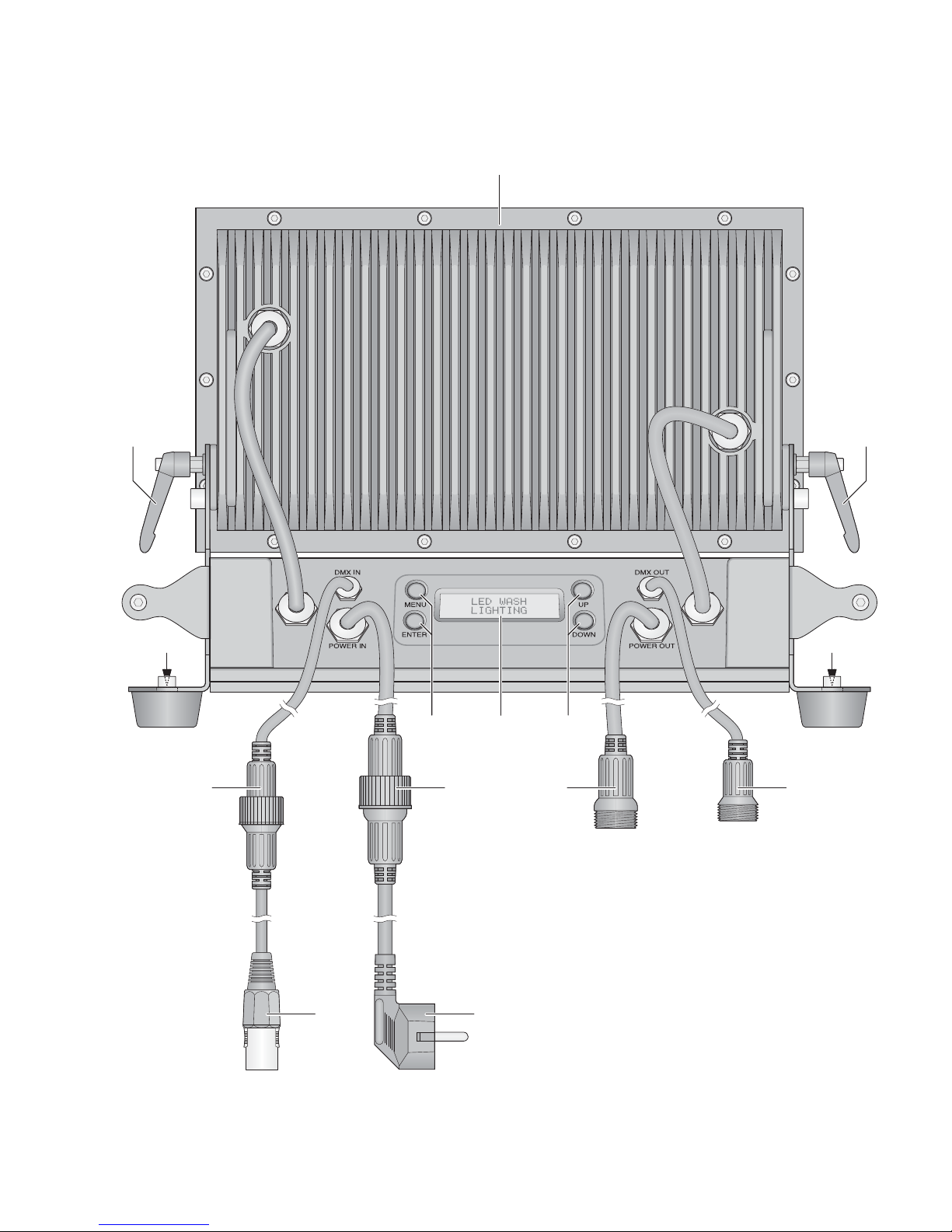
1 Übersicht der Bedienelemente
und Anschlüsse
1 neigbarer Scheinwerferkopf
2 Feststellschrauben für den Scheinwerferkopf
3 Löcher (∅11,5 mm) für die Befestigung von
zwei Schellen oder C-Haken zur Montage an
Leuchtenträgersystemen
4 Tasten zur Auswahl des Betriebsmodus und
zum Ändern von Einstellungen
5 Display
6 Stecker des Kabels DMX IN für den DMX-
Signaleingang:
Entweder über das Kabel mit dem XLR-Stecker (10) an ein Lichtsteuergerät anschließen
oder an den DMX-Signalausgang eines weiteren DMX-gesteuerten Gerätes
7 Stecker des Kabels POWER IN für die
Stromversorgung (230 V~ / 50 Hz):
Entweder über das Kabel mit dem Netzstecker (11) an eine Steckdose anschließen
oder an die Kupplung des Kabels POWER
OUT (8) eines weiteren ODW-2410RGBW
8 Kupplung des Anschlusses POWER OUT für
die Stromversorgung eines weiteren ODW2410RGBW
9 Kupplung des Anschlusses DMX OUT:
DMX-Signalausgang zum Anschluss an den
DMX-Signaleingang eines weiteren ODW2410RGBW oder eines anderen DMX-ge steuerten Geräts über das beiliegende Adapterkabel
10 XLR-Stecker des DMX-Signaleingangs
Pin 1 = Masse, Pin 2 = DMX−, Pin 3 = DMX+
11 Netzstecker zum Anschluss an eine Steck-
dose (230 V~ / 50 Hz)
2 Hinweise
für den sicheren Gebrauch
Das Gerät entspricht allen relevanten Richtlinien
der EU und ist deshalb mit gekennzeichnet.
G
Nehmen Sie das Gerät nicht in Betrieb und
trennen Sie es sofort vom Netz,
1. wenn sichtbare Schäden am Gerät oder am
Netzkabel vorhanden sind,
2. wenn nach einem Sturz oder Ähnlichem der
Verdacht auf einen Defekt besteht,
3. wenn Funktionsstörungen auftreten.
Geben Sie das Gerät in jedem Fall zur Reparatur in eine Fachwerkstatt.
G
Ein beschädigtes Netzkabel darf nur durch
eine Fachwerkstatt ersetzt werden.
G
Ziehen Sie den Netzstecker nie am Kabel aus
der Steckdose, fassen Sie am Stecker an.
G
Verwenden Sie zum Säubern des Scheinwerfergehäuses und der Schutzscheibe vor den
LEDs nur ein mildes Reinigungsmittel.
G
Wird das Gerät zweckentfremdet, nicht sicher
montiert, falsch bedient oder nicht fachgerecht repariert, kann keine Haftung für daraus
resultierende Sach- oder Personenschäden
und keine Garantie für das Gerät übernommen werden.
3 Einsatzmöglichkeiten
Dieser LED-Scheinwerfer dient zur Effektbeleuchtung. Der Scheinwerfer besitzt ein wetterfestes Aluminiumgehäuse (IP 66) und lässt sich
deshalb auch im Außenbereich einsetzen. Als
Lichtquelle werden 24 extrem helle LEDs verwendet. Mit den LEDs kann Licht in den drei
Grundfarben (Rot, Grün und Blau) und Weiß
abgestrahlt werden sowie in deren Mischfarben.
Außerdem sind Farbüberblendungen und Stroboskop-Effekte möglich. Der Scheinwerfer ist für
die Steuerung über ein DMX-Lichtsteuergerät
ausgelegt (wahlweise 11, 10, 6, 5, 4 oder 3
DMX-Steuerkanäle). Er kann aber auch eigenständig ohne Steuergerät betrieben werden.
Als Besonderheit bietet der Scheinwerfer
beim DMX-Betrieb mit 11 Kanälen die Verwendung von 66 Unteradressen. Dadurch lassen
sich über eine einzige DMX-Startadresse bis zu
66 Scheinwerfer (-gruppen) unabhängig voneinander steuern und die maximal mögliche
Anzahl DMX-gesteuerter Geräte wird erheblich
erhöht.
4 Montage
G
Platzieren Sie das Gerät immer so, dass im
Betrieb eine ausreichende Luftzirkulation ge währleistet ist.
G
Der Abstand zum angestrahlten Objekt und zu
angrenzenden Wänden sollte mindestens
15 cm betragen.
1. Den Scheinwerfer auf seine Gummifüße stel-
len. Zum Ausrichten des Scheinwerfers die
zwei Feststellschrauben (2) lösen. Die ge wünschte Neigung des Scheinwerferkopfs
(1) einstellen und die Schrauben wieder fest
an ziehen.
2. Alternativ lässt sich der Scheinwerfer an
einem Leuchtenträgersystem montieren. Den
Scheinwerfer über die beiden 11,5-mm-Lö cher (3) in den Seitenwinkeln mit zwei Montageschellen oder stabilen C-Haken z. B. an
einer Traverse befestigen.
5 Inbetriebnahme
Den Stecker (7) des Kabels POWER IN in die
Kupplung des beiliegenden Kabels mit dem
Netzstecker (11) stecken und die Steckverbindung mit der Überwurfmutter zusammenschrauben. Den Netzstecker in eine Steckdose
(230 V~/ 50 Hz) stecken. Der Scheinwerfer ist
damit eingeschaltet. Das Display (5) zeigt
LED
WASH LIGHTING
und es leuchtet für einige
Sekunden die Display-Beleuchtung.
VORSICHT!
Das Gerät darf nicht über einen Dimmer an die
Netzspannung angeschlossen werden!
Ist kein weiterer Scheinwerfer an der Kupplung
(8) des Kabels POWER OUT und der Kupplung
(9) des Kabels DMX OUT angeschlossen, unbedingt die beiliegenden Schutzkappen auf die
Kupplungen schrauben. Das Kabel POWER
OUT führt Netzspannung.
WARNUNG Blicken Sie nicht für längere Zeit
direkt in die Lichtquelle, das kann
zu Augenschäden führen.
Beachten Sie, dass sehr schnelle
Lichtwechsel bei fotosensiblen
Menschen und Epileptikern epileptische Anfälle auslösen können!
WARNUNG
Der Scheinwerfer muss fachgerecht und sicher montiert werden.
Soll das Gerät endgültig aus dem Be trieb genommen werden, übergeben
Sie es zur umweltgerechten Entsorgung
einem örtlichen Recyclingbetrieb.
WARNUNG Das Gerät wird mit lebensgefähr -
licher Netzspannung versorgt. Nehmen Sie deshalb nie selbst Eingriffe
am Gerät vor. Durch unsachgemäßes Vorgehen besteht die Gefahr
eines elektrischen Schlages.
Page 5
5
5.1 Anschluss mehrerer Scheinwerfer
Werden mehrere ODW-2410RGBW eingesetzt,
können die Scheinwerfer zur Stromversorgung
miteinander verbunden werden. Den ersten
Scheinwerfer vorerst noch nicht an eine Steckdose anschließen.
1) Den 1. Scheinwerfer über die Kupplung (8)
des Kabels POWER OUT mit dem Stecker
(7) des Kabels POWER IN des 2. Scheinwerfers verbinden. Genauso den 2. Scheinwerfer
mit dem 3. verbinden usw., bis alle Geräte in
einer Kette angeschlossen sind.
Sollten die Netzverbindungskabel zwischen den Scheinwerfern zu kurz sein, passende Verlängerungskabel verwenden, z. B.
ODP-34AC (2 m) oder ODP-34AC / 10 (10 m).
2) Am letzten Scheinwerfer auf die Kupplung (8)
des Kabels POWER OUT die beiliegende
Schutzkappe schrauben. Das Kabel führt
Netzspannung.
3) Den Netzstecker (11) des ersten Scheinwerfers in eine Steckdose (230 V~ / 50 Hz) stecken.
6 Bedienung
Alle Einstellungen des Gerätes erfolgen über ein
Menü im Display (5) mithilfe der Tasten MENU,
ENTER, UP und DOWN (4). Dabei behält das
Gerät immer die zuletzt angewählte Menüansicht. Zum Ändern einer Einstellung:
1) Die Taste MENU so oft drücken, bis sich die
Anzeige im Display nicht mehr ändert. Damit
ist die oberste Menüebene (Hauptmenü)
erreicht (Abbildung 2).
2) Mit der Taste UP oder DOWN den ge wünschten Menüpunkt anwählen. Der Pfeil
Ɗ
zeigt immer auf den gewählten Menüpunkt.
3) Zum Aufrufen des gewählten Menüpunkts die
Taste ENTER drücken. Das Display zeigt
jetzt die aktuelle Einstellung (
Ɗ
) für diesen
Menüpunkt an.
4) Mit der Taste UP oder DOWN die Einstellung
ändern.
5) Wenn Untermenüpunkte vorhanden sind,
können diese mit der Taste ENTER aufgerufen werden und deren Einstellungen mit der
Taste UP oder DOWN geändert werden.
6) Für weitere Einstellungen mit der Taste
MENU auf eine höhere Menüebene zurückspringen (ggf. bis zum Hauptmenü,
Be -
dienschritt 1).
Wird einige Sekunden lang keine Taste ge drückt, erlischt die Display-Beleuchtung. Beim
nächsten Tastendruck leuchtet das Display wieder.
Anhand der Kapitel 7 bis 9 die ge wünschten Einstellungen für den jeweiligen Be triebsmodus
vornehmen.
Übersicht Hauptmenü
7 Eigenständiger Betrieb
7.1 Farbstrahler und Stroboskop
In diesem Modus strahlt der Scheinwerfer konstant in einer einstellbaren Farbe. Zusätzlich
lässt sich die Stroboskop-Funktion einschalten.
1) Den Menüpunkt
Static Color
aufrufen.
2) Die folgenden Parameter einstellen:
ƊRed :
Helligkeit Rot (0 – 255)
green:
Helligkeit Grün (0 – 255)
blue :
Helligkeit Blau (0 – 255)
white:
Helligkeit Weiß (0 – 255)
strob:
Blitzfrequenz (0 – 20Hz)
des Stroboskops
3) Der Pfeil Ɗsteht immer vor der aktuellen Auswahl oder dem einzustellenden Wert. Zur
Einstellung des gewählten Parameters die
Taste ENTER drücken, mit der Taste UP
oder DOWN den Wert ändern und mit der
Taste MENU zur Parameterauswahl zurückkehren, um einen weiteren Parameter zu
ändern.
7.2 Verschiedene Weißtöne,
Speichern von 11 Farbtönen
In diesem Modus strahlt der Scheinwerfer weißes Licht ab. 11 verschiedene Weißtöne sind
gespeichert, die jedoch geändert werden können. Für jeden Weißton lässt sich die Helligkeit
für die Farben Rot, Grün, Blau und Weiß unterschiedlich einstellen, sodass dieser Modus auch
zum Speichern von 11 individuellen Farbtönen
genutzt werden kann.
1) Den Menüpunkt
CAL1 white
aufrufen.
Das Display zeigt jetzt mit dem Pfeil Ɗeinen
der 11 Speicherplätze an (
WT01… WT11)
und die LEDs leuchten im entsprechenden
Weißton.
2) Mit der Taste UP oder DOWN den ge wünschten Weißton wählen oder den Speicherplatz, dessen Einstellungen geändert
werden sollen.
3) Zum Ändern einer Einstellung nach dem
Anwählen des Speicherplatzes die Taste
ENTER drücken.
4) Die folgenden Parameter einstellen:
ƊRed :
Helligkeit Rot (0 – 255)
green:
Helligkeit Grün (0 – 255)
blue :
Helligkeit Blau (0 – 255)
white:
Helligkeit Weiß (0 – 255)
5) Der Pfeil Ɗsteht immer vor der aktuellen Auswahl oder dem einzustellenden Wert. Zur
Einstellung des gewählten Parameters die
Taste ENTER drücken, mit der Taste UP
oder DOWN den Wert ändern und mit der
Taste MENU zur Parameterauswahl zurückkehren, um einen weiteren Parameter zu
ändern.
6) Zum Aufrufen eines anderen Weißtones oder
zum Ändern der Einstellungen eines anderen
Speicherplatzes die Taste MENU so oft drücken, bis wieder die Speicherplatznummer
angezeigt wird. Dann die Bedienschritte 2 – 5
wiederholen.
7.3 Showprogramme und Szenenfolgen
10 Showprogramme (
Aut.01… Aut.10
)
sind im Scheinwerfer gespeichert. Außerdem
können 10 automatisch ablaufende Szenenfolgen (
Pro.01… Pro.10
) mit bis zu 30 Szenen selbst programmiert werden (Kap. 7.4).
Die Showprogramme und Szenenfolgen lassen
sich wie folgt starten:
1) Den Menüpunkt
Auto
aufrufen. Das Dis play zeigt jetzt mit dem Pfeil Ɗdas zuletzt
auf gerufene Showprogramm (
Aut.01
…
Aut.10
) oder die zuletzt aufgerufene Sze-
nenfolge (
Pro.01… Pro.10
) an.
2) Das Showprogramm oder die Szenenfolge
mit der Taste UP oder DOWN auswählen.
Die Showprogramme haben folgenden Ablauf:
Showprogramme
7.4 Szenenfolgen programmieren
Es lassen sich 10 Szenenfolgen auf einfache
Weise programmieren. Eine Szenenfolge kann
aus max. 30 Szenen bestehen. Für jede Szene
lässt sich die Farbe zusammen mit der Helligkeit
einstellen und die Stroboskop-Funktion mit
variabler Blitzfrequenz einschalten. Zudem lassen sich die Szenendauer und die Überblendzeit
bestimmen.
1) Den Menüpunkt
EDIT
aufrufen. Das Display
zeigt jetzt mit dem Pfeil Ɗdie zuletzt gewählte
Szenenfolge (
Pro01… Pro10
) an.
2) Die Nummer, unter der die Szenenfolge
gespeichert werden soll, mit der Taste UP
oder DOWN wählen und die Taste ENTER
drücken. Das Display zeigt die Nummer der
ersten Szene an (
SC01
).
3) Die Taste ENTER drücken und die folgenden
Parameter einstellen:
ƊRed :
Helligkeit Rot (0 – 255)
green:
Helligkeit Grün (0 – 255)
blue :
Helligkeit Blau (0 – 255)
white:
Helligkeit Weiß (0 – 255)
strob:
Blitzfrequenz (0 – 20Hz)
des Stroboskops
Time :
Szenendauer (time),
100 = 60 Sekunden
Fade :
Überblendzeit (fade)
4) Der Pfeil
Ɗ
steht immer vor der aktuellen Auswahl oder dem einzustellenden Wert. Zur
Einstellung des gewählten Parameters die
Taste ENTER drücken, mit der Taste UP
oder DOWN den Wert ändern und mit der
Taste MENU zur Parameterauswahl zurück-
Hauptmenü Beschreibung
Kapitel
Static Color
Farbstrahler/Stroboskop 7.1
Auto
Showprogramme (
Aut.
)/
programmierbare Szenenfolgen
(
Pro.
) abrufen 7.3
RUN
Master-/Slave-Betrieb 7.5
DMX Address
DMX-Startadresse 8.3
Personality
DMX-Betriebsart/Anzahl der Kanäle 8.2
ID Address
Unteradresse 8.3.1
EDIT
Szenenfolgen programmieren 7.4
SET
UPLD
: Szenenfolge auf andere
Scheinwerfer kopieren 7.5.1
REST
: Einstellungen zurücksetzen 9.4
ID
: Unteradressierung 8.3.1
REGW
: Farbbegrenzung 9.2
Dim
: Trägheit 9.3
CAL1 white
11 Weißtöne
oder individuelle Farben 7.2
CAL2 Parameter
Farbgrenzwerte einstellen 9.2
KEY LOCK
Tastensperre 9.1
Show -
programm
Ablauf
Aut.01
Stroboskop: weißes Licht
Aut.02
Ein- /Ausblenden: Rot, Grün, Blau, Weiß
Aut.03
Farbwechsel: Rot, Weiß, Grün, Blau
Aut.04
Farbwechsel: Rot, aus, Weiß, aus,
Grün, aus, Blau, aus
Aut.05
Überblenden: GrünRotBlau
Aut.06
Ein- /Ausblenden: Magenta, Gelb
Aut.07
Ein- /Ausblenden: Violett, Gelb
Aut.08
Ein- /Ausblenden: Violett
Aut.09
Ein- /Ausblenden: Türkis, Magenta
Aut.10
Ein- /Ausblenden: Violett, Grün
WARNUNG Der Gesamtstrom in den An -
schlusskabeln (7, 8) darf 10 A
nicht überschreiten, sonst kann
durch Überlastung ein Kabelbrand entstehen. Darum nur
maximal 9 Scheinwerfer mit einander verbinden.
D
A
CH
Page 6

kehren, um einen weiteren Parameter zu
ändern.
Hinweise
1. Die Zeitdauer einer Szene muss mindestens auf
den Wert
001
eingestellt werden, sonst lässt sich
die darauffolgende Szene nicht programmieren.
2. Soll von einer Szene auf die nächste Szene übergeblendet werden, muss für beide Szenen eine
Überblendzeit eingestellt werden.
5) Nachdem die erste Szene eingestellt ist, die
Taste MENU so oft drücken, bis der Pfeil
wieder auf die Szenennummer zeigt
(
ƊSC01
). Mit der Taste UP die zweite Szene
anwählen, die Taste ENTER drücken, die
Szene einstellen und den Vorgang für alle
anschließenden Szenen wiederholen.
6) Nachdem die letzte Szene eingestellt ist, die
Szenenfolge speichern: Direkt nach dem Einstellen eines Parameters die Taste ENTER
5 Sekunden gedrückt halten. Nach dem Lösen
der Taste muss das Display die Nummer der
Szenenfolge anzeigen (
Pro01… Pro10
),
anderenfalls wurde die Taste ENTER nicht
lange genug gedrückt.
Hinweise
1. Eine Szenenfolge muss komplett programmiert werden, bevor der Scheinwerfer von der Stromversorgung getrennt wird. Nach dem erneuten Einschalten
lässt sich eine Szenenfolge nicht mehr ändern; sie
kann nur neu programmiert werden. Zum Überschreiben einer Szenenfolge brauchen so die zuvor
programmierten Szenen nicht erst gelöscht zu werden.
2. Werden die Szenenfolgen nicht mit den Be dientasten (4) aufgerufen (Kap. 7.3), sondern über ein DMXLichtsteuergerät, bestimmt der DMX-Kanal 2 die
Szenendauer und der Kanal 3 die Überblendzeit
(Kap. 10.1.7). Der Kanal 2 muss dabei auf einen
DMX-Wert > 0 eingestellt sein, sonst bleibt der
Scheinwerfer dunkel.
7.5 Synchrone Steuerung mehrerer
Scheinwerfer (Master-Slave-Modus)
Es lassen sich mehrere ODW-2410RGBW zu sammenschließen. Das Hauptgerät (Master)
kann dann alle Nebengeräte (Slaves) synchron
steuern.
1) Die Scheinwerfer jeweils über die Kupplung
(9) des Kabels DMX OUT und den Stecker
(6) des Kabels DMX IN miteinander zu einer
Kette verbinden. Siehe dazu Kapitel 8.1
„DMX-Anschluss“, jedoch ohne den Bedienschritt 1 zu beachten.
2) Für den Master-Slave-Modus ist der Schein-
werfer ab Werk als Nebengerät eingestellt.
So muss nur der Scheinwerfer, der die
Nebengeräte steuern soll, als Hauptgerät
eingestellt werden.
Zum Ändern der Einstellung den Menüpunkt
RUN
aufrufen. Das Display zeigt:
DMX
= Hauptgerät
ƊSlave
= Nebengerät
Die aktuelle Einstellung ist mit dem Pfeil
gekennzeichnet. Bei Bedarf die Einstellung
mit der Taste UP oder DOWN ändern.
3) Das Hauptgerät auf die gewünschte Be triebsart einstellen (
Kapitel 7.1 – 7.3).
7.5.1 Szenenfolgen kopieren
Die programmierten Szenenfolgen eines Gerätes (Kap. 7.4) können auf andere Geräte über-
tragen werden. Dies ist sinnvoll, wenn mehrere
Geräte eigenständig mit gleichen Szenenfolgen
laufen sollen. Für den Synchronbetrieb bei verbundenen Geräten (Kap. 7.5) ist das Kopieren
der Szenenfolgen nicht erforderlich.
Das Gerät, dessen Szenenfolgen kopiert werden sollen, als Hauptgerät mit den anderen
Geräten verbinden (
Kapitel 7.5) und diese
als Nebengeräte einrichten:
1) Bei den Nebengeräten, die alle Szenenfolgen
vom Hauptgerät übernehmen sollen, den
Menüpunkt
RUN
aufrufen und die Option
ƊSlave
einstellen.
2) Am Hauptgerät den Menüpunkt
SET
und den
Untermenüpunkt
UPLD
aufrufen. Das Dis-
play zeigt
Password:
.
3) Folgende Tasten drücken:
UP, DOWN, UP, DOWN.
Das Drücken dieser Tasten wird jeweils mit
einem Stern *im Display angezeigt.
4) Den Kopiervorgang mit der Taste ENTER
starten. Während des Kopiervorgangs leuchten die Nebengeräte gelb, beim Auftreten
eines Fehlers rot und nach einem erfolgreichen Kopieren grün.
Hinweis: Die kopierten Szenenfolgen sind erst verfügbar, nachdem auf eine anderen Szenenfolge umgeschaltet oder die Stromversorgung unterbrochen
wurde.
8 Betrieb mit einem
DMX-Steuergerät
DMX ist die Abkürzung für Digital Multiplex und
bedeutet digitale Steuerung von mehreren DMXGeräten über eine gemeinsame Steuerleitung.
Zur Bedienung über ein DMX-Lichtsteuergerät
(z. B. DMX-1440 oder DMX-510USB von „img
Stage Line“) verfügt der Scheinwerfer über 11
DMX-Steuerkanäle. Er lässt sich je nach Bedarf
aber auch über nur 10, 6, 5, 4 oder 3 Kanäle
steuern. Die Funktionen der Kanäle und die
DMX-Werte sind im Kapitel 10.1 angegeben.
8.1 DMX-Anschluss
Für die DMX-Verbindung sind 3-polige XLR-An schlüsse mit folgender Kontaktbelegung vorhanden:
Pin 1 = Masse, Pin 2 = DMX−, Pin 3 = DMX+
Zum Anschluss sollten spezielle Kabel für die
DMX-Signalübertragung verwendet werden
(z. B. Kabel der CDMXN-Serie von „img Stage
Line“). Bei Leitungslängen ab 150 m und bei der
Steuerung von mehr als 32 Geräten über einen
DMX-Ausgang wird grundsätzlich das Zwischen schalten eines DMX-Aufholverstärkers
empfohlen (z. B. SR-103DMX von „img Stage
Line“).
1) Den Stecker (6) der Leitung DMX IN in die
Kupplung der beiliegenden Leitung mit dem
XLR-Stecker (10) stecken und die Steckverbindung mit der Überwurfmutter zusammenschrauben. Den XLR-Stecker über ein Verlängerungskabel an den DMX-Ausgang des
Lichtsteuergerätes anschließen oder, wenn
weitere DMX-gesteuerte Geräte verwendet
werden, an den DMX-Ausgang eines anderen DMX-gesteuerten Gerätes.
2) Werden weitere ODW-2410RGBW-Schein werfer verwendet, den ersten Scheinwerfer
über die Kupplung (9) des Kabels DMX OUT
mit dem Stecker (6) des Kabels DMX IN des
2. Scheinwerfers verbinden. Genauso den
2. Scheinwerfer mit dem 3. verbinden usw.,
bis alle Geräte in einer Kette angeschlossen
sind.
Sollten die DMX-Verbindungskabel zwischen den Scheinwerfern zu kurz sein, passende Verlängerungskabel verwenden, z. B.
ODP-34DMX (Länge 2 m) oder
ODP-34DMX / 10 (Länge 10 m).
Für den Anschluss anderer DMX-gesteuerter Geräte das Adapterkabel mit der XLRKupplung verwenden.
3) Um Störungen bei der Signalübertragung
auszuschließen, sollte bei langen Leitungen
bzw. bei einer Vielzahl von hintereinandergeschalteten Geräten der DMX-Ausgang des
letzten DMX-Gerätes der Kette mit einem
120-Ω-Widerstand (> 0,3 W) ab geschlossen
werden: In die XLR-Kupplung des mitgelieferten Adapterkabels einen entsprechenden
Abschlussstecker (z. B. DLT-123 von „img
Stage Line“) stecken. Bei einer Außeninstallation müssen die XLR-Kupplung und der Ab schluss stecker vor Feuchtigkeit geschützt
werden.
8.2 DMX-Betriebsart einstellen
Um den ODW-2410RGBW mit einem Lichtsteuergerät bedienen zu können, müssen die DMXStartadres se (Kap. 8.3) und die DMX-Betriebsart eingestellt werden. Aus der gewählten
Betriebsart ergibt sich die Anzahl der benötigten
DMX-Kanäle (3 – 11 Kanäle). Informieren Sie
sich im Kapitel 10.1 über die Funktionen, die in
der jeweiligen DMX-Betriebsart steuerbar sind
und wählen Sie danach oder eventuell nach der
Anzahl der verfügbaren Steuerkanäle am Lichtsteuergerät die DMX-Betriebsart aus:
1) Den Menüpunkt
Personality
aufrufen.
2) Die folgenden Einstellungen sind verfügbar:
ƊStage
11 Kanäle/10 Kanäle ohne Unteradressierung
(Kap. 10.1.7)
Arc.1
3 Kanäle
1 = Rot, 2 = Grün, 3 = Blau
Ar1.d
4 Kanäle
1 = Dimmer, 2 = Rot, 3 = Grün,
4 = Blau
Arc.2
4 Kanäle
1 = Rot, 2 = Grün, 3 = Blau,
4 = Weiß
Ar2.d
5 Kanäle
1 = Dimmer, 2 = Rot, 3 = Grün,
4 = Blau, 5 = Weiß
Ar2.s
6 Kanäle
1 = Dimmer, 2 = Rot, 3 = Grün,
4 = Blau, 5 = Weiß, 6 = Stroboskop
HSV
3 Kanäle
1 = Farbe, 2 = Farbsättigung,
3 = Helligkeit
3) Der Pfeil
Ɗ
zeigt die aktuelle Einstellung. Mit
der Taste UP oder DOWN die Einstellung
ändern.
D
A
CH
6
Page 7
8.3 DMX-Startadresse einstellen
Um den Scheinwerfer mit einem Lichtsteuergerät
bedienen zu können, muss die DMX-Startadres se für den ersten DMX-Kanal eingestellt werden.
Ist z. B. am DMX-Steuergerät die Adresse 17
zum Steuern der Funktion des ersten DMXKanals vorgesehen, am ODW-2410RGBW die
Startadresse 17 einstellen. Die weiteren DMXKanäle des ODW-2410RGBW sind dann automatisch den folgenden Adressen zugeordnet.
Nachfolgend ist ein Beispiel mit der Startadresse
17 aufgeführt:
DMX-Adressenbelegung
bei Verwendung der Startadresse 17
1) Den Menüpunkt
DMX Address
aufrufen.
2) Das Display zeigt die aktuelle DMX-Startadresse, z. B.
Addr:001
3) Mit der Taste UP oder DOWN die Startadresse einstellen.
8.3.1 Unteradressen verwenden
Im 11-Kanal-Betrieb (
Stage
, Kap. 8.2) lassen sich durch die Verwendung von Unteradressen bis zu 66 Scheinwerfer (-gruppen) über eine
einzige DMX-Startadresse nacheinander unabhängig steuern. Die maximal mögliche Anzahl
DMX-gesteuerter Geräte wird dadurch erheblich
erhöht. Die Anwahl von Scheinwerfern mit einer
Unteradresse erfolgt über den DMX-Kanal 11.
Scheinwerfer mit derselben Startadresse und
unterschiedlichen Unteradressen lassen sich
auch synchron steuern, wenn der DMX-Kanal 11
auf einen DMX-Wert von kleiner als 11 eingestellt wird.
1) Den Menüpunkt
SET
aufrufen und das
Untermenü
ID
.
2) Mit der Taste UP oder DOWN die Verwen-
dung der Unteradresse einschalten (
ID
Ɗon
). Ist die Unteradressierung ausgeschal-
tet (
off
), werden die Daten für Kanal 11 vom
Scheinwerfer ignoriert.
3) Mit der Taste MENU ins Hauptmenü zurück-
kehren und den Menüpunkt
ID Address
aufrufen.
4) Mit der Taste UP oder DOWN dem Schein-
werfer eine Unteradresse (1 – 66) zuweisen.
Um den Scheinwerfer bedienen zu können, am
Lichtsteuergerät den DMX-Kanal 11 auf den
DMX-Wert stellen, welcher der Unteradresse
des Scheinwerfers entspricht (
Kap. 10.1.7,
zweite Tabelle).
9 Weitere Funktionen
Hinweis: Um den Scheinwerfer per DMX steuern zu
können, nachdem eine in diesem Kapitel beschriebene
Einstellung durchgeführt worden ist, einen der folgenden Menüpunkte aufrufen:
RUN: DMX
,
DMX Address
,
Personality
,
ID Address
9.1 Tastensperre
Gegen eine unbefugte Bedienung kann eine
Tastensperre eingeschaltet werden. Bei aktiver
Sperre können Einstellungen erst nach der Eingabe einer bestimmten Tastenfolge vorgenommen werden.
1) Den Menüpunkt
KEY LOCK
aufrufen.
2) Mit der Taste UP oder DOWN die Tastensperre einschalten (
KEY Ɗon
) oder wieder
ausschalten (
off
).
Wurde
KEY Ɗon
gewählt, ist die Tastensperre
aktiv, sobald die Displaybeleuchtung erlischt.
Zur Bedienung bei aktiver Tastensperre:
1) Die Taste ENTER drücken, sodass im Display
Password:
erscheint.
2) Diese Tastenfolge eingeben:
UP, DOWN, UP, DOWN, ENTER
Dabei wird für die ersten vier Eingaben
jeweils ein
*
angezeigt.
3) Der Scheinwerfer kann jetzt normal bedient
werden. Nach dem Erlöschen der Displaybeleuchtung ist jedoch wieder die Tastensperre
aktiv, wenn sie nicht über den Menüpunkt
KEY LOCK
ausgeschaltet wurde.
9.2 Farben begrenzen
Die Helligkeitswerte der Farben Rot, Grün und
Blau lassen sich auf einen Maximalwert begrenzen. Dadurch können z. B. Unterschiede zu
anderen Scheinwerfern ausgeglichen werden,
wenn diese gemeinsam mit dem ODW2410RGBW gesteuert werden. Die Begrenzung
wirkt sich sowohl auf den eigenständigen
Betrieb als auch auf die DMX-Steuerung des
Scheinwerfers aus.
1) Den Menüpunkt
CAL2 Parameter
aufru-
fen und das Untermenü
REGW
.
2) Die folgenden Maximalwerte einstellen:
ƊRed :
Helligkeit Rot (0 – 255)
green:
Helligkeit Grün (0 – 255)
blue :
Helligkeit Blau (0 – 255)
3) Der Pfeil Ɗsteht immer vor der aktuellen Auswahl oder dem einzustellenden Wert. Zur
Einstellung des gewählten Parameters die
Taste ENTER drücken, mit der Taste UP
oder DOWN den Wert ändern und mit der
Taste MENU zur Parameterauswahl zurückkehren, um einen weiteren Parameter zu
ändern.
Ob die eingestellten Grenzwerte berücksichtigt
werden sollen, kann an einer anderen Stelle des
Menüs gewählt werden:
4) Mit der Taste MENU ins Hauptmenü zurückkehren und den Menüpunkt
SET
sowie das
Untermenü
REGW
aufrufen.
5) Mit der Taste UP oder DOWN die Begrenzung der Farben einschalten (
on
) oder aus-
schalten (
off
).
9.3 Künstliche Trägheit der LEDs
LEDs reagieren sehr schnell auf eine Änderung
der Helligkeitseinstellung. Um die Trägheit herkömmlicher Leuchtmittel zu simulieren, lässt
sich für die DMX-Steuerung eine künstliche
Trägheit in 4 Stufen einstellen. Bei der DMXBetriebsart
Stage
erfolgt diese Einstellung
über den DMX-Kanal 10 (Kap. 10.1.7). Für die
übrigen DMX-Betriebsarten die Einstellung wie
folgt vornehmen:
1) Den Menüpunkt
SET
aufrufen und das
Untermenü
Dim
.
2) Mit der Taste UP oder DOWN die Stufe der
Trägheit wählen (
1…4
) oder die künstliche
Trägheit ausschalten (
off
).
9.4 Scheinwerfer auf die
Werkseinstellung zurücksetzen
Ab Werk ist der Scheinwerfer wie folgt eingestellt:
Rücksetzwerte
Zum Zurücksetzen des Scheinwerfers auf die
Werkseinstellung:
1) Den Menüpunkt
SET
aufrufen und das
Untermenü
REST
.
Das Display zeigt
Password:
.
2) Folgende Tasten drücken:
UP, DOWN, UP, DOWN.
Das Drücken dieser Tasten wird jeweils mit
einem Stern
*
im Display angezeigt.
3) Das Zurücksetzen mit der Taste ENTER star-
ten.
Funktion Werkseinstellung
Farbstrahler
Static Color
Red
= 255,
green
= 255,
blue
= 255,
white
= —,
strob
= 00
Showprogramme
Auto
Aut.01
Master-Slave-Modus
RUN
Slave
DMX-Startadresse
DMX Address
Addr: 001
DMX-Kanäle
Personality
Stage
(10/11 Kanäle)
Unteradresse
ID Address
Addr:01
Funktion Unteradresse
SETID
off
(aus)
Funktion Farbbegrenzung
SETREGW
off
(aus)
Funktion LED-Trägheit
SETDim
off
(aus)
11 Weißtöne
CAL1 white
Speicherplatz: Rot, Grün, Blau, Weiß
WT01
: 255, 220, 5, 227
WT02
: 242, 222, 5, 227
WT03
: 255, 255, 61, 255
WT04
: 255, 255, 103, 255
WT05
: 255, 255, 130, 255
WT06
: 255, 255, 138, 255
WT07
: 255, 255, 153, 255
WT08
: 255, 255, 167, 255
WT09
: 255, 255, 180, 255
WT10
: 255, 255, 185, 255
WT11
: 255, 255, 202, 255
Farbbegrenzung
CAL2 Parameter
REGW Red
= 255,
green
= 255,
blue
= 255
Tastensperre
KEY LOCK
KEY off
(aus)
Anzahl der
DMX-Kanäle
belegte
DMX-Adressen
nächstmögliche Startadresse
für das
nachfolgende DMX-Gerät
3 17 – 19 20
4 17 – 20 21
5 17 – 21 22
6 17 – 22 23
11 17 – 27 28
7
D
A
CH
Page 8
10 Technische Daten
Datenprotokoll: . . . . . . . . DMX 512
Anzahl der DMX-Kanäle: wählbar zwischen
3, 4, 5, 6 oder 10/11
Lichtquelle: . . . . . . . . . . . 24 RGBW-LEDs
Leistung je LED: . . . . . 8 W
Abstrahlwinkel: . . . . . . 45°
Stromversorgung: . . . . . . 230 V~ / 50 Hz
Leistungsaufnahme: . . . . max. 250 VA
Gehäuseschutzart: . . . . . IP 66
Abmessungen: . . . . . . . . 430 × 300 × 220 mm
Gewicht: . . . . . . . . . . . . . 11 kg
10.1DMX-Funktionen
10.1.1 Modus
Arc.1
(3 Kanäle)
10.1.2 Modus
HSV
(3 Kanäle)
10.1.3 Modus
Ar1.d
(4 Kanäle)
10.1.4 Modus
Arc.2
(4 Kanäle)
10.1.5 Modus
Ar2.d
(5 Kanäle)
10.1.6 Modus
Ar2.s
(6 Kanäle)
DMXKanal
DMX-
Wert
Funktion
1 0– 255 Helligkeit Rot
2 0– 255 Helligkeit Grün
3 0– 255 Helligkeit Blau
DMXKanal
DMX-
Wert
Funktion
1 0– 255 Dimmer (Gesamthelligkeit)
2 0– 255 Helligkeit Rot
3 0– 255 Helligkeit Grün
4 0– 255 Helligkeit Blau
5 0– 255 Helligkeit Weiß
6
0– 15 kein Stroboskop
16 – 255 Stroboskop 1 – 20 Hz
DMXKanal
DMX-
Wert
Funktion
1 0– 255 Dimmer (Gesamthelligkeit)
2 0– 255 Helligkeit Rot
3 0– 255 Helligkeit Grün
4 0– 255 Helligkeit Blau
5 0– 255 Helligkeit Weiß
DMXKanal
DMX-
Wert
Funktion
1 0– 255 Helligkeit Rot
2 0– 255 Helligkeit Grün
3 0– 255 Helligkeit Blau
4 0– 255 Helligkeit Weiß
DMXKanal
DMX-
Wert
Funktion
1 0– 255 Dimmer (Gesamthelligkeit)
2 0– 255 Helligkeit Rot
3 0– 255 Helligkeit Grün
4 0– 255 Helligkeit Blau
DMXKanal
DMX-
Wert
Funktion
1 0– 255 Farbe
2 0– 255 Farbsättigung
3 0– 255 Helligkeit
D
A
CH
8
Diese Bedienungsanleitung ist urheberrechtlich für MONACOR
®
INTERNATIONAL GmbH & Co. KG
geschützt. Eine Reproduktion für eigene kommerzielle Zwecke – auch auszugsweise – ist untersagt.
DMXKanal
DMX-
Wert
Funktion
1 0– 255 Dimmer (Gesamthelligkeit)
1
2 0– 255
Helligkeit Rot
1
Szenendauer, wenn Kanal 8 = 110 … 255
3 0– 255
Helligkeit Grün
1
Überblendzeit, wenn Kanal 8 = 110 … 255
4 0– 255 Helligkeit Blau
1
5 0– 255 Helligkeit Weiß
1
6
0– 10 keine Funktion
11 – 20
RotGelb
21 – 30
GelbGrün
31 – 40
GrünTürkis
41 – 50
TürkisBlau
51 – 60
BlauMagenta
61 – 70
MagentaRot
71 – 80
RotRosa
81 – 90
RosaRot
91 – 100
GrünRot
101 – 110
BlauRot
111 – 120
BlauGrün
121 – 130
BlauGelb
131 – 140
TürkisRot
141 – 150
GrünMagenta
151 – 160
BlauRotGrün
161 – 170
TürkisGelbMagenta
171 – 180
RotGrünBlauWeiß
181 – 190
TürkisGrünGelbRotMagentaBlau
191 – 200 Weiß, max. Helligkeit
201 – 205
WT01 (Weißton 1,Kap. 7.2)
206 – 210 WT02
211 – 215 WT03
216 – 220 WT04
221 – 225 WT05
226 – 230 WT06
231 – 235 WT07
236 – 240 WT08
241 – 245 WT09
246 – 250 WT10
251 – 255 WT11
7
0 – 255 Geschwindigkeit, wenn Kanal 6 = 11… 190
0– 15 kein Stroboskop
16 – 255 Stroboskop 1 … 20 Hz
8
0– 9 keine Funktion
10 – 19
Showprogramm Aut.01 (Abb. 3)
2
20–29 Showprogramm Aut.02
2
30–39 Showprogramm Aut.03
2
40–49 Showprogramm Aut.04
2
50–59 Showprogramm Aut.05
2
60–69 Showprogramm Aut.06
2
70–79 Showprogramm Aut.07
2
80–89 Showprogramm Aut.08
2
90–99 Showprogramm Aut.09
2
100 –109 Showprogramm Aut.10
2
110 – 119
Szenenfolge Pro.01 (Kap. 7.4)
3
120 – 129 Szenenfolge Pro.02
3
130 – 139 Szenenfolge Pro.03
3
140 – 149 Szenenfolge Pro.04
3
150 – 159 Szenenfolge Pro.05
3
160 – 169 Szenenfolge Pro.06
3
170 – 179 Szenenfolge Pro.07
3
180 – 189 Szenenfolge Pro.08
3
190 – 199 Szenenfolge Pro.09
3
200 – 255 Szenenfolge Pro.10
3
9 0– 255 Geschwindigkeit, wenn Kanal 8 = 10 … 109 (Aut…)
2
10
0– 49
keine künstliche Trägheit (Kap. 9.3)
50–99 Trägheitstufe 1
4
100 – 149 Trägheitstufe 2
4
150 – 199 Trägheitstufe 3
4
200 – 255 Trägheitstufe 4
4
11 0 – 255
Unteradressen, folgende Tabelle
DMX-
Wert
Unter-
adresse
DMX-
Wert
Unter-
adresse
0– 10
alle
11 – 19 01 223 34
20 – 29
02 224 35
30 – 39
03 225 36
40 – 49
04 226 37
50 – 59
05 227 38
60 – 69
06 228 39
70 – 79
07 229 40
80 – 89
08 230 41
90 – 99
09 231 42
100 – 109
10 232 43
110 – 119
11 233 44
120 – 129
12 234 45
130 – 139
13 235 46
140 – 149
14 236 47
150 – 159
15 237 48
160 – 169
16 238 49
170 – 179
17 239 50
180 – 189
18 240 51
190 – 199
19 241 52
200 – 209
20 242 53
210
21 243 54
211
22 244 55
212
23 245 56
213
24 246 57
214
25 247 58
215
26 248 59
216
27 249 60
217
28 250 61
218
29 251 62
219
30 252 63
220
31 253 64
221
32 254 65
222
33 255 66
Kanal 11:
Anwahl von Scheinwerfern über
die Unteradresse
ID Address
10.1.7 Modus
Stage
(11 Kanäle oder 10 Kanäle ohne
die Nutzung von Unteradressen)
Zusätzliche Bedingungen der Funktionen:
1
wenn Kanal 6 = 0 … 10 und K. 8 = 0 … 9
oder
Kanal 6 = 0 … 10 und K. 7 = 5 … 255
2
wenn Kanal 7 = 0 … 4 und K. 6 = 0 … 10
3
wenn Kanal 7 = 0 … 4 und K. 6 = 0 … 10
und K. 2 = 1 … 255
4
wenn Kanal 6 = 0 … 10 und K. 8 = 0 … 9
und K. 7 = 0 … 15
oder
Kanal 6 = 0 … 10 und K. 7 = 5 … 15
Änderungen vorbehalten.
Page 9
9
GB
DMX LED Floodlight
These instructions are intended for the installer
of the floodlight and for operators without any
technical training. Please read these instructions
carefully prior to installation and keep them for
later reference. All operating elements and connections described can be found on the fold-out
page 3.
Contents
1 Operating Elements and Connections 9
2 Safety Notes . . . . . . . . . . . . . . . . . . . . . 9
3 Applications . . . . . . . . . . . . . . . . . . . . . 9
4 Installation . . . . . . . . . . . . . . . . . . . . . . 9
5 Setting into Operation . . . . . . . . . . . . . 9
5.1 Connecting multiple floodlights . . . . . . 10
6 Operation . . . . . . . . . . . . . . . . . . . . . . 10
7 Independent Operation . . . . . . . . . . . 10
7.1 Colour floodlight and stroboscope . . . . 10
7.2 Different shades of white,
storing 11 shades of colour . . . . . . . . . 10
7.3 Show programs and
sequences of scenes . . . . . . . . . . . . . . 10
7.4 Programming sequences of scenes . . 10
7.5 Synchronous control of multiple flood-
lights (master / slave mode) . . . . . . . . . 11
7.5.1 Copying sequences of scenes . . . . . . . 11
8 Operation with a DMX Controller . . . 11
8.1 DMX connection . . . . . . . . . . . . . . . . . 11
8.2 Setting the DMX operation mode . . . . . 11
8.3 Setting the DMX start address . . . . . . . 12
8.3.1 Using subaddresses . . . . . . . . . . . . . . 12
9 Additional Functions . . . . . . . . . . . . . 12
9.1 Key lock . . . . . . . . . . . . . . . . . . . . . . . . 12
9.2 Limiting colours . . . . . . . . . . . . . . . . . . 12
9.3 Artificial response time of the LEDs . . . 12
9.4 Resetting the floodlight to its
factory settings . . . . . . . . . . . . . . . . . . . 12
10 Specifications . . . . . . . . . . . . . . . . . . 13
10.1 DMX functions
10.1.1 Mode
Arc.1
(3 channels) . . . . . . . . 13
10.1.2 Mode
HSV
(3 channels) . . . . . . . . . . . 13
10.1.3 Mode
Ar1.d
(4 channels) . . . . . . . . 13
10.1.4 Mode
Arc.2
(4 channels) . . . . . . . . 13
10.1.5 Mode
Ar2.d
(5 channels) . . . . . . . . 13
10.1.6 Mode
Ar2.
(6 channels) . . . . . . . . . 13
10.1.7 Mode
Stage
(10 /11 channels) . . . . . 13
1 Operating Elements
and Connections
1 Tiltable floodlight head
2 Setscrews for the floodlight head
3 Holes (∅11.5 mm) to fasten two clamps or
C hooks for mounting the floodlight to lighting
stand systems
4 Buttons to select the operation mode and to
change settings
5 Display
6 Plug of the cable DMX IN for the DMX signal
input:
Using the cable fitted with the XLR plug (10),
either connect the plug to a light controller or
to the DMX signal output of another DMX
controlled unit
7 Plug of the cable POWER IN for power sup-
ply (230 V~ / 50 Hz):
Either connect the plug to the mains socket,
using the cable fitted with the mains plug
(11), or connect it to the inline jack of the
cable POWER OUT (8) of another ODW2410RGBW
8 Inline jack of the connection POWER OUT for
power supply of another ODW-2410RGBW
9 Inline jack of the connection DMX OUT:
DMX signal output for connection to the DMX
signal input of another ODW-2410RGBW or
another DMX-controlled unit via the adapter
cable supplied
10 XLR plug of the DMX signal input
pin 1 = ground, pin 2 = DMX−, pin 3 = DMX+
11 Mains plug for connection to a mains socket
(230 V~ / 50 Hz)
2 Safety Notes
The unit corresponds to all relevant directives of
the EU and is therefore marked with
.
G
Do not operate the unit and immediately disconnect it from the mains
1. if the unit or the mains cable is visibly damaged,
2. if a defect might have occurred after the unit
was dropped or suffered a similar accident,
3. if malfunctions occur.
In any case the unit must be repaired by
skilled personnel.
G
A damaged mains cable must only be
replaced by skilled personnel.
G
Never pull the mains cable for disconnecting
the mains plug from the socket, always seize
the plug.
G
For cleaning the floodlight housing and the
protective pane in front of the LEDs, only use
a mild detergent.
G
No guarantee claims for the unit and no liability for any resulting personal damage or material damage will be accepted if the unit is used
for other purposes than originally intended, if it
is not safely mounted or not correctly operated, or if it is not repaired in an expert way.
G
Important for U. K. Customers!
The wires in this mains lead are coloured in
accordance with the following code:
green/yellow = earth
blue = neutral
brown = live
As the colours of the wires in the mains lead of
this appliance may not correspond with the
coloured markings identifying the terminals in
your plug, proceed as follows:
1. The wire which is coloured green and yellow must be connected to the terminal in the
plug which is marked with the letter E or by
the earth symbol , or coloured green or
green and yellow.
2. The wire which is coloured blue must be
connected to the terminal which is marked
with the letter N or coloured black.
3. The wire which is coloured brown must be
connected to the terminal which is marked
with the letter L or coloured red.
Warning – This appliance must be earthed.
3 Applications
This LED floodlight is used for effect illumination.
The floodlight features a weatherproof aluminium housing (IP 66) and is therefore also suitable for outdoor applications. 24 extra bright
LEDs are used as a light source. The LEDs can
emit light in the three primary colours (red, green
and blue) and in white as well as coloured light
created from additive colour mixing. Crossfading
from one colour to another and stroboscope
effects are also supported. The floodlight is
designed for control via a DMX light controller
(optionally 11, 10, 6, 5, 4 or 3 DMX control channels). However, it can also be operated on its
own without a controller.
As a special feature, the floodlight supports
66 subaddresses when used in DMX mode with
11 channels. Thus, it is possible to independently control up to 66 floodlights (floodlight
groups) via a single DMX start address and the
maximum number of DMX-controlled units possible is substantially increased.
4 Installation
G
Always position the floodlight in a way that ensures sufficient air circulation during operation.
G
Always keep a minimum distance of 15 cm to
the object illuminated and to the adjoining walls.
1. Place the floodlight on its rubber feet. To
align the floodlight, loosen the two setscrews
(2). Tilt the floodlight head (1) as desired and
then retighten the screws.
2. As an alternative, the floodlight can be
mounted to a lighting stand system: Use two
mounting clamps or stable C hooks to fasten
the floodlight via the two 11.5 mm holes (3) at
the lateral brackets to a cross bar, for example.
5 Setting into Operation
WARNING To prevent damage to your eyes,
never look directly into the light
source for any length of time.
Please note that fast changes in
lighting may trigger epileptic
seizures with photosensitive persons or persons with epilepsy!
WARNING
Install the floodlight safely and
expertly.
If the unit is to be put out of operation
definitively, take it to a local recycling
plant for a disposal which is not harmful
to the environment.
WARNING The unit uses dangerous mains
voltage. Leave servicing to skilled
personnel only; inexpert handling
of the unit may result in electric
shock.
Page 10
Connect the plug (7) of the cable POWER IN to
the inline jack of the supplied cable fitted with the
mains plug (11) and then use the cap nut to
screw the plug-in connection together. Connect
the mains plug to a mains socket (230 V~ /
50 Hz). The floodlight will be switched on.
LED
WASH LIGHTING
will appear on the display
(5), and the display will be illuminated for a few
seconds.
CAUTION!
Do not connect the unit to the mains voltage via
a dimmer!
If no further floodlight is connected to the inline
jack (8) of the cable POWER OUT and to the
inline jack (9) of the cable DMX OUT, make
absolutely sure to screw the protective covers
onto the inline jacks. The cable POWER OUT
carries mains voltage.
5.1 Connecting multiple floodlights
If multiple ODW-2410RGBW are used, the floodlights can be interconnected for power supply.
Do not connect the first floodlight to a mains
socket for the time being.
1) Use the inline jack (8) of the cable POWER
OUT to connect the first floodlight to the plug
(7) of the cable POWER IN of the second
floodlight. Proceed in the same way to connect the second floodlight to the third one etc.
until all floodlights are connected in a chain.
If the mains connection cables between
the floodlights are too short, use suitable
extension cables such as ODP-34AC (2 m) or
ODP-34AC / 10 (10 m).
2) At the last floodlight, screw the protective
cover supplied onto the inline jack (8) of the
cable POWER OUT. The cable carries mains
voltage.
3) Connect the mains plug (11) of the first floodlight to a mains socket (230 V~ / 50 Hz).
6 Operation
All settings of the unit are made via a menu on
the display (5) by means of the buttons MENU,
ENTER, UP and DOWN (4). The unit will always
display the most recently selected menu view.
To change a setting:
1) Press the button MENU repeatedly until the
indication on the display does not change
anymore: The top menu level (main menu)
has been reached (
fig. 2).
2) Use the button UP or DOWN to select the
menu item desired. The arrow
Ɗ
will always
point to the menu item selected.
3) Press the button ENTER to call up the menu
item selected. The display will indicate the
current setting (
Ɗ
) for this menu item.
4) Use the button UP or DOWN to change the
setting.
5) If submenu items are available, use the button ENTER to call them up and then use the
button UP or DOWN to change their settings.
6) For further settings, press the button MENU
to go to a higher menu level (if required, go to
the main menu,
step 1).
The display illumination will extinguish after a
few seconds if no button is pressed. It will light
up again when a button is pressed.
Make the desired settings for the respective
operation mode, observing the instructions given
in chapters 7 to 9.
Overview of the main menu
7 Independent Operation
7.1 Colour floodlight and stroboscope
In this mode, the floodlight constantly radiates
light in an adjustable colour. The stroboscope
function can additionally be activated.
1) Call up the menu item
Static Color
.
2) Set the following parameters:
ƊRed :
Brightness of red (0 – 255)
green:
Brightness of green (0 – 255)
blue :
Brightness of blue (0– 255)
white:
Brightness of white (0 – 255)
strob:
Flash frequency (0 – 20 Hz)
of the stroboscope
3) The arrow
Ɗ
always precedes the current
selection or the value to be set. To set the
parameter selected: Press the button ENTER
and use the button UP or DOWN to change
the setting; then press the button MENU to
return to the parameter selection and to
change another parameter.
7.2 Different shades of white,
storing 11 shades of colour
In this mode, the floodlight radiates white light.
11 different shades of white are stored which,
however, can be changed, if required. For each
shade of white, the brightness of the colours red,
green, blue and white may be set to different values so that this mode can also be used to store
11 individual shades of colour.
1) Call up the menu item
CAL1 white
. The
arrow Ɗon the display will point to one of the
11 storage locations (WT01… WT11), and
the LEDs will light up in the corresponding
shade of white.
2) Use the button UP or DOWN to select the
desired shade of white or to select the storage
location whose settings are to be changed.
3) To change a setting after selecting a storage
location, press the button ENTER.
4) Set the following parameters:
ƊRed :
Brightness of red (0 – 255)
green:
Brightness of green (0 – 255)
blue :
Brightness of blue (0 – 255)
white:
Brightness of white (0 – 255)
5) The arrow
Ɗ
always precedes the current
selection or the value to be set. To set the
parameter selected: Press the button ENTER
and use the button UP or DOWN to change
the setting; then press the button MENU to
return to the parameter selection and to
change another parameter.
6) To call up another shade of white or to
change the settings of another storage location, press the button MENU repeatedly until
the storage location number is shown again.
Then repeat steps 2 – 5.
7.3 Show programs and
sequences of scenes
10 show programs (
Aut.01… Aut.10
) are
stored on the floodlight. In addition, 10 automatic
sequences of scenes (
Pro.01… Pro.10
)
with up to 30 scenes each can be programmed
(
chapter 7.4). To start the show programs
and sequences of scenes:
1) Call up the menu item
Auto
. The arrow Ɗon
the display points to the show program
(
Aut.01
…
Aut.10
) or sequence of
scenes (
Pro.01… Pro.10
) most recently
called up.
2) Use the button UP or DOWN to select the
show program or the sequence of scenes.
The sequence of the show programs is as follows:
Show programs
7.4 Programming sequences of scenes
10 sequences of scenes can be easily programmed. Each sequence may include up to
30 scenes. For each scene, the colour can be
set together with the brightness and the stroboscope function with variable flash frequency can
be activated. In addition, the length of the scenes
and the crossfading time can be defined.
1) Call up the menu item
EDIT
. The arrow Ɗon
the display will point to the sequence of
scenes most recently selected (
Pro01
…
Pro10
).
2) Use the button UP or DOWN to select the
number to which the sequence of scenes is to
be stored, and then press the button ENTER.
The display will show the number of the first
scene (
SC01
).
Show
program
Sequence
Aut.01
Stroboscope: white light
Aut.02
Fade-in / fade-out: red, green, blue, white
Aut.03
Colour change: red, white, green, blue
Aut.04
Colour change: red, off, white, off,
green, off, blue, off
Aut.05
Crossfading: greenredblue
Aut.06
Fade-in / fade-out: magenta, yellow
Aut.07
Fade-in / fade-out: purple, yellow
Aut.08
Fade-in / fade-out: purple
Aut.09
Fade-in / fade-out: cyan, magenta
Aut.10
Fade-in / fade out: purple, green
Main menu Description
Chapter
Static Color
Colour floodlight / stroboscope 7.1
Auto
Call up show programs (
Aut.
)/
programmable sequences of scenes
(
Pro.
) 7.3
RUN
Master / slave mode 7.5
DMX Address
DMX start address 8.3
Personality
DMX operation mode /
number of channels 8.2
ID Address
Subaddress 8.3.1
EDIT
Program sequences of scenes 7.4
SET
UPLD
: Copy sequence of scenes to
other floodlights 7.5.1
REST
: Reset settings 9.4
ID
: Subaddressing 8.3.1
REGW
: Colour limitation 9.2
Dim
: Response time 9.3
CAL1 white
11 shades of white
or individual colours 7.2
CAL2 Parameter
Set colour limitation values 9.2
KEY LOCK
Key lock 9.1
WARNING The total current in the connec-
tion cables (7, 8) must not
exceed 10 A; otherwise, a
cable fire may occur due to
overload. Therefore, only interconnect 9 floodlights as a maximum.
10
GB
Page 11

3) Press the button ENTER and set the following parameters:
ƊRed :
Brightness of red (0 – 255)
green:
Brightness of green (0 – 255)
blue :
Brightness of blue (0 – 255)
white:
Brightness of white (0 – 255)
strob:
Flash frequency (0 – 20 Hz)
of the stroboscope
Time :
Length of scene (time),
100 = 60 seconds
Fade :
Crossfading time
4) The arrow Ɗalways precedes the current
selection or the value to be set. To set the
parameter selected: Press the button ENTER
and use the button UP or DOWN to change
the setting; then press the button MENU to
return to the parameter selection and to
change another parameter.
Notes
1. The length of a scene must at least be set to the
value
001
; otherwise, it is not possible to pro-
gram the subsequent scene.
2. To crossfade from one scene to the next, a cross-
fading time must be set for both scenes.
5) Once the first scene has been set, press the
button MENU repeatedly until the arrow
points to the number of scene (
ƊSC01
). Use
the button UP to select the second scene,
press the button ENTER, set the scene and
then repeat this procedure for all subsequent
scenes.
6) Once the final scene has been set, store the
sequence of scenes: Immediately after setting a parameter, keep the button ENTER
pressed for 5 seconds. When the button is
released, the number of the sequence
(
Pro01… Pro10
) will appear on the display; if not, the button ENTER has not been
pressed long enough.
Notes
1. A sequence of scenes must have been completely
programmed before the floodlight is disconnected
from the power supply. After the floodlight has been
switched on again, the sequence of scenes cannot
be changed anymore; it can only be programmed
again. To overwrite a sequence of scenes, it is not
necessary to delete the previously programmed
scenes first.
2. When the sequence of scenes is not called up by
means of the control buttons (4) [chapter 7.3.] but via
a DMX light controller, DMX channel 2 will define the
length of a scene and DMX channel 3 will define the
crossfading time (chapter 10.1.7). Channel 2 must be
set to a DMX value > 0; otherwise, the floodlight will
remain dark.
7.5 Synchronous control of multiple
floodlights (master/ slave mode)
Multiple ODW-2410RGBW can be interconnected. The master unit will then synchronously
control all slave units.
1) Use the inline jack (9) of the cable DMX OUT
and the plug (6) of the cable DMX IN to connect the floodlights in a chain. Please refer
to chapter 8.1, “DMX connection”, skipping
step 1.
2) The floodlight is factory-set to act as a slave
unit in master / slave mode. Thus, only the
floodlight that is to control the slave units
must be defined as a master unit.
Call up the menu item
RUN
to change the
setting. The display will show the following:
DMX
= master unit
ƊSlave
= slave unit
An arrow will point to the current setting. If
required, use the button UP or DOWN to
change the setting.
3) Set the master unit to the operation mode
desired (
chapters 7.1 – 7.3).
7.5.1 Copying sequences of scenes
The programmed sequences of scenes of a unit
(chapter 7.4.) can be copied to other units. This
is useful when multiple units are to run independently with the same sequences of scenes.
For synchronous operation on interconnected
units (chapter 7.5), it is not necessary to copy the
sequences of scenes.
Define the unit whose sequences of scenes are
to be copied as a master unit and connect it to
the other units (
chapter 7.5); set up the other
units as slave units:
1) At the slave units that are to adopt all
sequences of scenes from the master unit,
call up the menu item
RUN
and set the option
ƊSlave
.
2) At the master unit, call up the menu item
SET
and the submenu item
UPLD. Password:
will appear on the display.
3) Press the following buttons:
UP, DOWN, UP, DOWN.
For each press of a button, an asterisk
*
will
appear on the display.
4) Use the button ENTER to start copying. During the copy process, the slave units will light
up in yellow; they will light up in red in case of
an error; and they will light up in green once
the copy process has been successfully completed.
Note: The sequences of scenes copied will only be
available after a different sequence of scenes has been
selected or after the power supply has been interrupted.
8 Operation with
a DMX Controller
DMX (Digital Multiplex) means digital control of
multiple DMX units via a common control line.
For operation by means of a DMX light controller
(e. g. DMX-1440 or DMX-510USB from “img
Stage Line”), the floodlight is equipped with 11
DMX control channels. However, it can also be
controlled by 10, 6, 5, 4 or 3 channels, if
required. The functions of the channels and the
corresponding DMX values can be found in
chapter 10.1.
8.1 DMX connection
For DMX connection, 3-pole XLR connections
with the following pin configuration are available:
pin 1 = ground, 2 = DMX−, 3 = DMX+
For the connection, special cables for DMX sig-
nal transmission (e. g. cables of the CDMXN
series from “img Stage Line”) should be used.
For cable lengths exceeding 150 m and for the
control of more than 32 units via a single DMX
output, the insertion of a DMX level matching
amplifier (e. g. SR-103DMX from “img Stage
Line”) is recommended.
1) Connect the plug (6) of the cable DMX IN to
the inline jack of the cable supplied that is fitted with the XLR plug (10), and then use the
cap nut to screw the plug-in connection
together. Using an extension cable, connect
the XLR plug to the DMX output of the light
controller or, if additional DMX-controlled
units are used, to the DMX output of another
DMX-controlled unit.
2) If additional floodlights ODW-2410RGBW are
used, use the inline jack (9) of the cable DMX
OUT to connect the first floodlight to the plug
(6) of the cable DMX IN of the second floodlight. Proceed in the same way to connect the
second floodlight to the third one etc. until all
floodlights are connected in a chain.
If the DMX connection cables between the
floodlights are too short, use suitable extension
cables, e. g. ODP-34DMX (length: 2 m) or
ODP-34DMX /10 (length: 10 m).
To connect other DMX-controlled units, use
the adapter cable fitted with the XLR inline
jack.
3) To prevent interference in signal transmission: For long cables or for a great number of
units connected in series, terminate the DMX
output of the last DMX unit in the chain with a
120 Ω resistor (> 0.3 W): Connect an appropriate terminating plug (e. g. DLT-123 from
“img Stage Line”) to the XLR inline jack of the
supplied adapter cable. For outdoor installation, protect the XLR inline jack and the terminating plug against humidity.
8.2 Setting the DMX operation mode
To operate the ODW-2410RGBW by means of a
light controller, set the DMX start address
(chapter 8.3) and the DMX operation mode.
The DMX operation mode selected will determine the number of the DMX channels required
(3 – 11 channels). Please refer to chapter 10.1
for the functions that can be controlled with the
respective DMX operation modes, and then,
based on this information or based on the number of the control channels available at the light
controller, select the DMX operation mode:
1) Call up the menu item
Personality
.
2) The following settings are available:
ƊStage
11 channels /10 channels without
subaddressing
(
chapter 10.1.7)
Arc.1
3 channels
1 = red, 2 = green, 3 = blue
Ar1.d
4 channels
1 = dimmer, 2 = red, 3 = green,
4 = blue
Arc.2
4 channels
1 = red, 2 = green, 3 = blue,
4 = white
Ar2.d
5 channels
1= dimmer, 2 = red, 3 = green,
4 = blue, 5 = white
Ar2.s
6 channels
1 = dimmer, 2 = red, 3 = green,
4 = blue, 5 = white, 6 = stroboscope
HSV
3 channels
1 = colour, 2 = colour saturation,
3 = brightness
3) The arrow
Ɗ
points to the current setting. Use
the button UP or DOWN to change the setting.
11
GB
Page 12

8.3 Setting the DMX start address
For control of the floodlight by means of a light
controller, the DMX start address for the first
DMX channel must be set. If, for example, the
address 17 is to be used for controlling the function of the first DMX channel, set the start
address at the ODW-2410RGBW to 17. All other
DMX channels of the ODW-2410RGBW will be
automatically assigned to the subsequent ad dresses. The following table is an example with
the start address 17:
DMX address assignment for start address 17
1) Call up the menu item
DMX Address
.
2) The current DMX start address will appear on
the display, e. g.
Addr:001
.
3) Use the button UP or DOWN to set the start
address.
8.3.1 Using subaddresses
In the 11-channel mode (
Stage
, chapter 8.2),
subaddresses may be used to independently control up to 66 floodlights (floodlight groups) one
after the other via a single DMX start address.
Thus, the maximum number of DMX units possible is substantially increased. DMX channel 11 is
used to select floodlights with a subaddress.
Floodlights having the same start address and different subaddresses may be controlled in sync if
DMX channel 11 is set to a DMX value less than
11.
1) Call up the menu item
SET
and the submenu
ID
.
2) Use the button UP or DOWN to activate the
use of subaddresses (
ID Ɗon
). When sub-
addressing is deactivated (
off
), the flood-
light will ignore the data for channel 11.
3) Use the button MENU to return to the main
menu, and then call up the menu item
ID
Address
.
4) Use the button UP or DOWN to assign a sub-
addresss (1 – 66) to the floodlight.
To be able to operate the floodlight, set the DMX
channel 11 at the light controller to the DMX
value that corresponds to the subaddress of the
floodlight (
chapter 10.1.7, second table).
9 Additional Functions
Note: To be able to control the floodlight by DMX after
one of the settings described in this chapter has been
made, call up one of the following menu items:
RUN: DMX
,
DMX Address
,
Personality
,
ID Address
9.1 Key lock
A key lock may be used to protect the floodlight
against unauthorized operation. When the key
lock is activated, settings can only be made after
a specific sequence of buttons has been
pressed.
1) Call up the menu item
KEY LOCK
.
2) Use the button UP or DOWN to activate the
key lock (
KEY Ɗon
) or to deactivate it (
off
).
When
KEY Ɗon
has been selected, the key lock
function will be active as soon the display illumination extinguishes.
To operate the floodlight with the key lock activated:
1)
Press the button ENTER so that
Password:
appears on the display.
2) Press the following buttons:
UP, DOWN, UP, DOWN, ENTER
For each of the first four buttons pressed, an
asterisk
*
will appear on the display.
3) The floodlight can now be operated as usual.
The key lock, however, will be active again
when the display illumination extinguishes
(unless the key lock has been deactivated by
means of the menu item
KEY LOCK
).
9.2 Limiting colours
A maximum value can be defined for the brightness of the colours red, green and blue. Thus, it
is, for example, possible to compensate differences to other floodlights if they are controlled
together with the ODW-2410RGBW. The colour
limitation will apply to both independent and
DMX-controlled floodlight operation.
1) Call up the menu item
CAL2 Parameter
and the submenu
REGW
.
2) Set the following maximum values:
ƊRed :
brightness of red (0 – 255)
green:
brightness of green (0 – 255)
blue :
brightness of blue (0– 255)
3) The arrow
Ɗ
always precedes the current
selection or the value to be set. To set the
parameter selected: Press the button ENTER
and use the button UP or DOWN to change
the setting; then press the button MENU to
return to the parameter selection and to
change another parameter.
To define if the limitation values set are to be
applied:
4) Use the button MENU to return to the main
menu, then call up the menu item
SET
and
the submenu
REGW
.
5) Use the button UP or DOWN to activate the
colour limitation function (
on
) or to deactivate
it (
off
).
9.3 Artificial response time of the LEDs
LEDs almost instantly respond to changes in
brightness setting. To simulate the response
time of conventional lamps, four different levels
of artificial response time are available for DMX
control. For the DMX operation mode
Stage
,
make this setting by means of DMX channel 10
(chapter 10.1.7). For the other DMX operation
modes, proceed as follows:
1) Call up the menu item
SET
and the submenu
Dim
.
2) Use the button UP or DOWN to select the
response time level (
1…4
) or to deactivate
the artificial response time (
off
).
9.4 Resetting the floodlight
to its factory settings
The factory settings of the floodlight are as follows:
Reset values
To reset the floodlight to its factory settings:
1) Call up the menu item
SET
and the submenu
REST
.
Password:
appears on the display.
2) Press the following buttons:
UP, DOWN, UP, DOWN.
For each press of a button, an asterisk
*
will
appear on the display.
3) Use the button ENTER to start the reset.
Function Factory setting
Colour floodlight beam
Static Color
Red
= 255,
green
= 255,
blue
= 255,
white
= —,
strob
= 00
Show programs
Auto
Aut.01
Master / slave mode
RUN
Slave
DMX start address
DMX Address
Addr: 001
DMX channels
Personality
Stage
(10/11 channels)
Subaddress
ID Address
Addr:01
Subaddress function
SETID
off
Colour limitation function
SETREGW
off
LED response time
function
SETDim
off
11 shades of white
CAL1 white
Storage location:
red, green, blue, white
WT01
: 255, 220, 5, 227
WT02
: 242, 222, 5, 227
WT03
: 255, 255, 61, 255
WT04
: 255, 255, 103, 255
WT05
: 255, 255, 130, 255
WT06
: 255, 255, 138, 255
WT07
: 255, 255, 153, 255
WT08
: 255, 255, 167, 255
WT09
: 255, 255, 180, 255
WT10
: 255, 255, 185, 255
WT11
: 255, 255, 202, 255
Colour limitation
CAL2 Parameter
REGW Red
= 255,
green
= 255,
blue
= 255
Key lock
KEY LOCK
KEY off
Number of
DMX channels
DMX addresses
assigned
Next possible
start address for the
subsequent DMX unit
3 17– 19 20
4 17– 20 21
5 17– 21 22
6 17– 22 23
11 17 – 27 28
12
GB
Page 13

13
GB
All rights reserved by MONACOR®INTERNATIONAL GmbH & Co. KG. No part of this instruction
manual may be reproduced in any form or by any means for any commercial use.
10 Specifications
Data protocol: . . . . . . . . . . DMX 512
Number of DMX channels: selectable: 3, 4,
5, 6 or 10 / 11
Light source: . . . . . . . . . . . 24 RGBW LEDs
Power of each LED: . . . 8 W
Beam angle: . . . . . . . . . 45°
Power supply: . . . . . . . . . . 230 V~ / 50 Hz
Power consumption: . . . . . 250 VA max.
Protective class of housing: IP 66
Dimensions: . . . . . . . . . . . 430 × 300 ×220 mm
Weight: . . . . . . . . . . . . . . . 11 kg
10.1DMX Functions
10.1.1 Mode
Arc.1
(3 channels)
10.1.2 Mode
HSV
(3 channels)
10.1.3 Mode
Ar1.d
(4 channels)
10.1.4 Mode
Arc.2
(4 channels)
10.1.5 Mode
Ar2.d
(5 channels)
10.1.6 Mode
Ar2.s
(6 channels)
DMX
channel
DMX
value
Function
1 0– 255 Brightness of red
2 0– 255 Brightness of green
3 0– 255 Brightness of blue
DMX
channel
DMX
value
Function
1 0– 255 Dimmer (total brightness)
2 0– 255 Brightness of red
3 0– 255 Brightness of green
4 0– 255 Brightness of blue
5 0– 255 Brightness of white
6
0– 15 No stroboscope
16 – 255 Stroboscope 1 – 20 Hz
DMX
channel
DMX
value
Function
1 0– 255 Dimmer (total brightness)
2 0– 255 Brightness of red
3 0– 255 Brightness of green
4 0– 255 Brightness of blue
5 0– 255 Brightness of white
DMX
channel
DMX
value
Function
1 0– 255 Brightness of red
2 0– 255 Brightness of green
3 0– 255 Brightness of blue
4 0– 255 Brightness of white
DMX
channel
DMX
value
Function
1 0– 255 Dimmer (total brightness)
2 0– 255 Brightness of red
3 0– 255 Brightness of green
4 0– 255 Brightness of blue
DMX
channel
DMX
value
Function
1 0– 255 Colour
2 0– 255 Colour saturation
3 0– 255 Brightness
DMX
channel
DMX
value
Function
1 0– 255 Dimmer (total brightness)
1
2 0– 255
Brightness of red
1
Length of scene, if channel 8 = 110 … 255
3 0– 255
Brightness of green
1
Crossfading time, if channel 8 = 110 … 255
4 0– 255 Brightness of blue
1
5 0– 255 Brightness of white
1
6
0– 10 No function
11 – 20
RedYellow
21 – 30
YellowGreen
31 – 40
GreenCyan
41 – 50
CyanBlue
51 – 60
BlueMagenta
61 – 70
MagentaRed
71 – 80
RedPink
81 – 90
PinkRed
91 – 100
GreenRed
101 – 110
BlueRed
111 – 120
BlueGreen
121 – 130
BlueYellow
131 – 140
CyanRed
141 – 150
GreenMagenta
151 – 160
BlueRedGreen
161 – 170
CyanYellowMagenta
171 – 180
RedGreenBlueWhite
181 – 190
CyanGreenYellowRedMagentaBlue
191 – 200 White, max. brightness
201 – 205
WT01 (shade of white 1,chapter 7.2)
206 – 210 WT02
211 – 215 WT03
216 – 220 WT04
221 – 225 WT05
226 – 230 WT06
231 – 235 WT07
236 – 240 WT08
241 – 245 WT09
246 – 250 WT10
251 – 255 WT11
7
0 – 255 Speed, if channell 6 = 11… 190
0– 15 No stroboscope
16 – 255 Stroboscope 1 … 20 Hz
8
0– 9 No function
10 – 19
Show program Aut.01 (fig. 3)
2
20–29 Show program Aut.02
2
30–39 Show program Aut.03
2
40–49 Show program Aut.04
2
50–59 Show program Aut.05
2
60–69 Show program Aut.06
2
70–79 Show program Aut.07
2
80–89 Show program Aut.08
2
90–99 Show program Aut.09
2
100 –109 Show program Aut.10
2
110 – 119
Sequence of scenes Pro.01 (chapter 7.4)
3
120 – 129 Sequence of scenes Pro.02
3
130 – 139 Sequence of scenes Pro.03
3
140 – 149 Sequence of scenes Pro.04
3
150 – 159 Sequence of scenes Pro.05
3
160 – 169 Sequence of scenes Pro.06
3
170 – 179 Sequence of scenes Pro.07
3
180 – 189 Sequence of scenes Pro.08
3
190 – 199 Sequence of scenes Pro.09
3
200 – 255 Sequence of scenes Pro.10
3
9 0– 255 Speed, if channel 8 = 10… 109 (Aut…)
2
10
0– 49
No artificial response time (chapter 9.3)
50–99 Response time level 1
4
100 – 149 Response time level 2
4
150 – 199 Response time level 3
4
200 – 255 Response time level 4
4
11 0 – 255
Subaddresses, following table
DMX
value
Sub-
address
DMX
value
Sub-
address
0– 10
All
11 – 19 01 223 34
20 – 29 02 224 35
30 – 39
03 225 36
40 – 49
04 226 37
50 – 59
05 227 38
60 – 69
06 228 39
70 – 79
07 229 40
80 – 89
08 230 41
90 – 99
09 231 42
100 – 109
10 232 43
110 – 119
11 233 44
120 – 129
12 234 45
130 – 139
13 235 46
140 – 149
14 236 47
150 – 159
15 237 48
160 – 169
16 238 49
170 – 179
17 239 50
180 – 189
18 240 51
190 – 199
19 241 52
200 – 209
20 242 53
210
21 243 54
211
22 244 55
212
23 245 56
213
24 246 57
214
25 247 58
215
26 248 59
216
27 249 60
217
28 250 61
218
29 251 62
219
30 252 63
220
31 253 64
221
32 254 65
222
33 255 66
Channel 11:
Selection of floodlights via the
sub address
ID Address
10.1.7 Mode
Stage
(11 channels or 10 channels without
using subaddresses)
Additional conditions of the functions:
1
If channel 6 = 0 … 10 and ch. 8 = 0 … 9
or
channel 6 = 0 … 10 and ch. 7 = 5 … 255
2
If channel 7 = 0 … 4 and ch. 6 = 0 … 10
3
If channel 7 = 0 … 4 and ch. 6 = 0 … 10
and ch. 2 = 1 … 255
4
If channel 6 = 0 … 10 and ch. 8 = 0 … 9
and ch. 7 = 0 … 15
or
channel 6 = 0 … 10 and ch. 7 = 5 … 15
Subject to technical modification.
Page 14

Projecteur DMX à LEDs
Cette notice sʼadresse à lʼinstallateur du projecteur et à lʼutilisateur nʼayant pas de formation
technique spécifique. Veuillez lire la notice avec
attention avant lʼinstallation y conservez-la pour
vous y reporter ultérieurement. Vous trouverez
sur la page 3, dépliable, les éléments et branchements décrits.
Table des matières
1 Eléments et branchements . . . . . . . . 14
2 Conseils dʼutilisation et de sécurité 14
3 Possibilités dʼutilisation . . . . . . . . . . 14
4 Montage . . . . . . . . . . . . . . . . . . . . . . . 14
5 Mise en service . . . . . . . . . . . . . . . . . 14
5.1 Branchement de plusieurs projecteurs 15
6 Utilisation . . . . . . . . . . . . . . . . . . . . . . 15
7 Fonctionnement indépendant . . . . . 15
7.1 Projecteur de couleurs et stroboscope 15
7.2 Différentes tonalités de blanc, mémo -
risation de 11 tonalités de couleur . . . . 15
7.3 Programmes Show et
suites de scènes . . . . . . . . . . . . . . . . . 15
7.4 Programmation de suites de scènes . . 15
7.5 Gestion synchrone de plusieurs
projecteurs (mode Master/ Slave) . . . . 16
7.5.1 Copie de suites de scènes . . . . . . . . . . 16
8 Fonctionnement avec
un contrôleur DMX . . . . . . . . . . . . . . . 16
8.1 Branchement DMX . . . . . . . . . . . . . . . 16
8.2 Réglage du mode de
fonctionnement DMX . . . . . . . . . . . . . . 16
8.3 Réglage de lʼadresse de
démarrage DMX . . . . . . . . . . . . . . . . . 17
8.3.1 Utilisation des sous-adresses . . . . . . . 17
9 Autres fonctions . . . . . . . . . . . . . . . . 17
9.1 Verrouillage des touches . . . . . . . . . . . 17
9.2 Limitation des couleurs . . . . . . . . . . . . 17
9.3 Inertie artificielle des LEDs . . . . . . . . . 17
9.4 Réinitialisation du projecteur sur
les réglages usine . . . . . . . . . . . . . . . . 17
10 Caractéristiques techniques . . . . . . . 18
10.1 Fonctions DMX . . . . . . . . . . . . . . . . . . 18
10.1.1 Mode
Arc.1
(3 canaux) . . . . . . . . . . 18
10.1.2 Mode
HSV
(3 canaux) . . . . . . . . . . . . 18
10.1.3 Mode
Ar1.d
(4 canaux) . . . . . . . . . . 18
10.1.4 Mode
Arc.2
(4 canaux) . . . . . . . . . . 18
10.1.5 Mode
Ar2.d
(5 canaux) . . . . . . . . . . 18
10.1.6 Mode
Ar2.s
(6 canaux) . . . . . . . . . . 18
10.1.7 Mode
Stage
(10/11 canaux) . . . . . . 18
1 Eléments et branchements
1 Tête orientable du projecteur
2 Vis de fixation pour la tête du projecteur
3 Trous (∅11,5 mm) pour fixer deux colliers ou
crochets C pour monter lʼappareil sur un portique de lumière
4 Touches pour sélectionner le mode de fonc-
tionnement et modifier les réglages
5 Affichage
6 Fiche du cordon DMX IN pour lʼentrée signal
DMX :
En utilisant le cordon avec la fiche XLR (10),
reliez soit la fiche du cordon DMX IN à un
contrôleur soit à la sortie de signal DMX dʼun
autre appareil géré par DMX
7 Fiche du cordon POWER IN pour lʼalimenta-
tion (230 V~ / 50 Hz) :
Soit reliez la fiche à la prise secteur en utilisant le cordon avec la fiche secteur (11), soit
reliez-la à la prise du cordon POWER OUT
(8) dʼun autre ODW-2410RGBW
8 Prise du branchement POWER OUT pour
lʼalimentation dʼun autre ODW-2410RGBW
9 Prise du branchement DMX OUT :
Sortie signal DMX pour brancher à lʼentrée
signal DMX dʼun autre ODW-2410RGBW ou
dʼun autre appareil géré par DMX via le cordon adaptateur livré
10 Fiche XLR de lʼentrée signal DMX
Pin 1 = masse, pin 2 = DMX−, pin 3 = DMX+
11 Fiche secteur pour brancher à une prise sec-
teur 230 V~ / 50 Hz
2 Conseils dʼutilisation
et de sécurité
Lʼappareil répond à toutes les directives nécessaires de lʼUnion européenne et porte donc le
symbole .
G
Ne faites pas fonctionner lʼappareil ou débranchez-le immédiatement du secteur lorsque :
1. des dommages visibles apparaissent sur
l'appareil ou sur le cordon secteur,
2. après une chute ou un cas similaire, vous
avez un doute sur l'état de l'appareil,
3. des dysfonctionnements apparaissent.
Dans tous les cas, les dommages doivent être
réparés par un technicien spécialisé.
G
Tout cordon secteur endommagé ne doit être
remplacé que par un technicien spécialisé.
G
Ne débranchez jamais l'appareil en tirant sur
le cordon secteur ; retirez toujours le cordon
secteur en tirant la fiche.
G
Pour nettoyer le boîtier du projecteur et la vitre
de protection devant les LEDs, utilisez uniquement un produit de nettoyage doux.
G
Nous déclinons toute responsabilité en cas de
dommages matériels ou corporels résultants
si lʼappareil est utilisé dans un but autre que
celui pour lequel il a été conçu, sʼil nʼest pas
monté dʼune manière sûre, s'il n'est pas correctement utilisé ou sʼil nʼest pas réparé par
une personne habilitée, en outre, la garantie
deviendrait caduque.
3 Possibilités dʼutilisation
Le projecteur à LEDs permet des effets d'éclairage. Il est équipé dʼun boîtier étanche en aluminium (IP 66) et peut être utilisé en extérieur.
Comme source de lumière, il possède 24 LEDs
très claires, permettant de diffuser une lumière
dans les trois couleurs primaires (rouge, vert,
bleu) et blanc et dans les couleurs de mixage
correspondantes. De plus, des transitions de
couleurs et des effets stroboscope sont possibles. Le projecteur est prévu pour un fonctionnement via un contrôleur DMX (au choix, 11, 10, 6,
5, 4 ou 3 canaux DMX). Il peut également fonctionner seul sans contrôleur.
Particularité du ODW-2410RGBW : en mode
DMX, avec 11 canaux, il permet dʼutiliser 66 sous adresses. Via une seule adresse de démarrage
DMX, on peut ainsi gérer de manière indépendante jusquʼà 66 projecteurs (groupes de projecteurs), le nombre maximal possible dʼappareils
gérés par DMX augmente donc de manière
conséquente.
4 Montage
G
Placez toujours lʼappareil de telle sorte que,
pendant le fonctionnement, une circulation
suffisante dʼair soit assurée.
G
La distance avec lʼobjet à éclairer et les cloisons autour doit être de 15 cm au moins.
1. Placez le projecteur sur ses pieds caout-
chouc. Pour orienter le projecteur, desserrez
les deux vis de fixation (2). Réglez lʼinclinaison voulue de la tête du projecteur (1) et resserrez les vis.
2. Le projecteur peut également être monté sur
un portique de lumière. Via les deux trous de
11,5 mm (3) dans les étriers latéraux, fixez le
projecteur avec deux colliers de montage ou
deux crochets C solides, par exemple sur
une traverse.
5 Mise en service
Reliez la fiche (7) du cordon POWER IN à la
prise du cordon livré avec la fiche secteur (11) et
vissez la connexion avec lʼécrou. Reliez la fiche
secteur à une prise 230 V~ / 50 Hz. Le projecteur
est alors allumé, lʼaffichage (5) indique
LED
WASH LIGHTING
et lʼéclairage de lʼaffichage
brille pendant quelques secondes.
ATTENTION !
Lʼappareil ne doit pas être relié via un dimmer à
lʼalimentation.
Si aucun autre projecteur nʼest relié à la prise (8)
du cordon POWER OUT et à la prise (9) du cordon DMX OUT, vissez impérativement les
caches de protection livrés sur les prises. Le cordon POWER OUT est porteur de tension secteur.
AVERTISSEMENT Ne regardez jamais directe-
ment la source de lumière
pendant un certain temps,
cela pourrait causer des troubles de la vision.
N'oubliez pas que des changements très rapides de
lumière peuvent déclencher
des crises d'épilepsie chez les
personnes photosensibles et
épileptiques.
AVERTISSEMENT
L'appareil doit être monté de
manière professionnelle et
sûre.
Lorsque lʼappareil est définitivement retiré
du service, vous devez le déposer dans
une usine de recyclage adaptée pour
contribuer à son élimination non polluante.
AVERTISSEMENT Lʼappareil est alimenté par une
tension dangereuse. Ne touchez jamais l'intérieur de l'appareil ! Risque de décharge
électrique.
14
F
B
CH
Page 15

5.1 Branchement de plusieurs
projecteurs
Si plusieurs ODW-2410RGBW sont utilisés, ils
peuvent être reliés entre eux pour lʼalimentation.
Ne reliez pas dans un premier temps le premier
projecteur à une prise secteur.
1) Via la prise (8) du cordon POWER OUT,
reliez le premier projecteur à la fiche (7) du
cordon POWER IN du deuxième projecteur.
Reliez de la même manière le deuxième projecteur au troisième et ainsi de suite jusquʼà
ce que tous les appareils soient reliés en une
chaîne.
Si les cordons DMX entre les projecteurs
sont trop courts, utilisez les cordons prolongateur adéquats, par exemple ODP-34AC
(2 m) ou ODP-34AC /10 (10 m).
2) Sur le dernier projecteur, vissez le cache de
protection livré sur la prise (8) du cordon
POWER OUT. Le cordon est porteur de tension secteur.
3) Reliez la fiche secteur (11) du premier projecteur à une prise secteur 230 V~ / 50 Hz.
6 Utilisation
Tous les réglages de lʼappareil sʼeffectuent via
un menu sur lʼaffichage (5), via les touches
MENU, ENTER, UP et DOWN (4). Lʼappareil
affiche toujours la dernière vue de menu sélectionnée. Pour modifier un réglage :
1) Appuyez sur la touche MENU jusquʼà ce que
lʼaffichage ne se modifie plus. Vous avez
alors atteint la plage supérieure du menu
(menu principal,
schéma 2).
2) Avec la touche UP ou DOWN, sélectionnez le
point de menu souhaité. La flèche Ɗindique
toujours le point de menu sélectionné.
3) Pour appeler le point de menu souhaité,
appuyez sur la touche ENTER. Lʼaffichage
indique le réglage actuel (
Ɗ
) pour ce point de
menu.
4) Avec la touche UP ou DOWN, modifiez le
réglage.
5) Si des points de sous-menus existent, vous
pouvez les appeler avec la touche ENTER et
modifier leurs réglages avec la touche UP ou
DOWN.
6) Pour dʼautres réglages, revenez au niveau
supérieur du menu avec la touche MENU (si
besoin jusquʼau menu principal,
point 1).
Si aucune touche nʼest utilisée pendant
quelques secondes, lʼéclairage de lʼaffichage
sʼéteint. Il se rallume à la prochaine activation
dʼune touche.
Effectuez les réglages pour chaque mode de
fonctionnement selon les indications des chapitres 7 à 9.
Présentation du menu principal
7 Fonctionnement indépendant
7.1 Projecteur de couleurs
et stroboscope
Avec ce mode, le projecteur diffuse une couleur
réglable de manière constante. On peut en plus
activer la fonction stroboscope.
1) Appelez le point de menu
Static Color
.
2) Réglez les paramètres suivants :
ƊRed :
luminosité rouge (0– 255)
green:
luminosité vert (0 – 255)
blue :
luminosité bleu (0– 255)
white:
luminosité blanc (0 – 255)
strob:
fréquence des éclaires du stroboscope (0 – 20 Hz)
3) La flèche
Ɗ
est toujours devant la sélection
en cours ou la valeur à régler. Pour régler le
paramètre sélectionné, appuyez sur la
touche ENTER, modifiez la valeur avec la
touche UP ou DOWN et revenez à la sélection de paramètres avec la touche MENU
pour modifier un autre paramètre.
7.2
Différentes tonalités de blanc, mémorisation de 11 tonalités de couleur
Avec ce mode, le projecteur diffuse une lumière
blanche. 11 tonalités différentes de blanc sont
mémorisées, elles peuvent être modifiées. Pour
chaque tonalité de blanc, on peut régler de
manière distincte la luminosité pour les couleurs
rouge, vert, bleu et blanc pour que ce mode
puisse également être utilisé pour mémoriser 11
tonalités individuelles de couleurs.
1) Appelez le point de menu
CAL1 white
. La
flèche Ɗsur lʼaffichage indique un des 11
emplacements de mémoire (WT01… WT11)
et les LEDs brillent dans la tonalité de blanc
correspondante.
2) Avec la touche UP ou DOWN, sélectionnez la
tonalité de blanc souhaitée ou lʼemplacement
de mémoire dont les réglages doivent être
modifiés.
3) Pour modifier un réglage, appuyez sur la
touche ENTER après avoir sélectionné lʼemplacement de mémoire.
4) Réglez les paramètres suivants :
ƊRed :
luminosité rouge (0– 255)
green:
luminosité vert (0 – 255)
blue :
luminosité bleu (0– 255)
white:
luminosité blanc (0 – 255)
5) La flèche
Ɗ
est toujours devant la sélection
en cours ou la valeur à régler. Pour régler le
paramètre sélectionné, appuyez sur la
touche ENTER, modifiez la valeur avec la
touche UP ou DOWN et revenez à la sélection de paramètres avec la touche MENU
pour modifier un autre paramètre.
6) Pour appeler une autre tonalité de blanc ou
modifier les réglages dʼun autre emplacement de mémoire, appuyez sur la touche
MENU jusquʼà ce que le numéro de lʼemplacement de mémoire soit à nouveau affiché.
Répétez ensuite les points 2 à 5.
7.3 Programmes Show
et suites de scènes
10 programmes Show (
Aut.01… Aut.10
)
sont mémorisés dans le projecteur. De plus, 10
suites de scènes à défilement automatique
(
Pro.01… Pro.10
) avec jusquʼà 30 scènes
peuvent être programmées (chapitre 7.4).
Les programmes Show et suites de scènes peuvent être démarrés comme suit :
1) Appelez le point de menu
Auto
. Avec la
flèche Ɗ, lʼaffichage indique maintenant le
dernier programme Show appelé (
Aut.01
…
Aut.10
) ou la dernière suite de scène
appelée (
Pro.01… Pro.10
).
2) Sélectionnez le programme Show ou la suite
de scènes avec la touche UP ou DOWN. Les
programmes Show défilent comme suit :
Programmes Show
7.4 Programmation de suites de scènes
Il est possible de programmer 10 suites de
scènes simplement. Une suite de scènes peut
se composer de 30 scènes au plus. Pour chaque
scène, on peut régler la couleur avec la luminosité et activer la fonction stroboscope avec une
fréquence dʼéclairs variable. De plus, on peut
définir la durée de la scène et la durée de transition.
1) Appelez le point de menu
EDIT
. Avec la
flèche Ɗ, lʼaffichage indique la dernière suite
de scènes sélectionnée (
Pro01… Pro10
).
2) Avec la touche UP ou DOWN, sélectionnez le
numéro sous lequel la suite de scène doit
être mémorisée et appuyez sur la touche
ENTER. Lʼaffichage indique le numéro de la
première scène (
SC01
).
3) Appuyez sur la touche ENTER et réglez les
paramètres suivants :
ƊRed :
luminosité rouge (0– 255)
green:
luminosité vert (0 – 255)
blue :
luminosité bleu (0– 255)
white:
luminosité blanc (0 – 255)
strob:
fréquence des éclaires du stroboscope (0 – 20 Hz)
Time :
durée de scène (time),
100 = 60 secondes
Fade :
durée de transition (fade)
4) La flèche
Ɗ
est toujours devant la sélection
en cours ou la valeur à régler. Pour régler le
paramètre sélectionné, appuyez sur la
Programme
Show
Défilement
Aut.01
stroboscope : lumière blanche
Aut.02
fondu-enchaîné : rouge, vert, bleu, blanc
Aut.03
changement couleurs :
rouge, blanc, vert, bleu
Aut.04
changement couleurs : rouge, éteint, blanc,
éteint, vert, éteint, bleu, éteint
Aut.05
transition : vertrougebleu
Aut.06
fondu-enchaîné : magenta, jaune
Aut.07
fondu-enchaîné : violet, jaune
Aut.08
fondu-enchaîné : violet
Aut.09
fondu-enchaîné : turquoise, magenta
Aut.10
fondu-enchaîné : violet, vert
Menu principal
Description
chapitre
Static Color
projecteur couleurs / stroboscope 7.1
Auto
programmes Show (
Aut.
)/
appeler suites de scènes programmables
(
Pro.
) 7.3
RUN
mode Master / Slave 7.5
DMX Address
adresse de démarrage DMX 8.3
Personality
mode de fonctionnement DMX /
nombre de canaux 8.2
ID Address
sous-adresse 8.3.1
EDIT
programmation de suites de scènes 7.4
SET
UPLD
: copie dʼune suite de scènes
sur dʼautres projecteurs 7.5.1
REST
: réinitialisation des réglages 9.4
ID
: utilisation des
sous-adresses 8.3.1
REGW
: limitation des couleurs 9.2
Dim
: inertie 9.3
CAL1 white
11 tonalités de blanc
ou couleurs individuelles 7.2
CAL2 Parameter
réglage des valeurs limites
de couleur 9.2
KEY LOCK
verrouillage des touches 9.1
AVERTISSEMENT Le courant total dans les
cordons de branchement
(7, 8) ne doit pas dépasser
10 A. Sinon un cordon peut
prendre feu à cause dʼune
surcharge. Cʼest pourquoi
9 projecteurs au plus peuvent être reliés ensemble.
15
F
B
CH
Page 16

touche ENTER, modifiez la valeur avec la
touche UP ou DOWN et revenez à la sélection de paramètres avec la touche MENU
pour modifier un autre paramètre.
Conseils
1. La durée dʼune scène doit être réglée sur la
valeur
001
au moins sinon, la scène suivante ne
peut pas être programmée.
2. Si vous voulez faire un fondu-enchaîné dʼune
scène vers la suivante, il faut régler une durée de
transition pour les deux scènes.
5) Une fois la première scène réglée, appuyez
sur la touche MENU jusquʼà ce que la flèche
soit à nouveau devant le numéro de la scène
(
ƊSC01
). Avec la touche UP, sélectionnez la
deuxième scène, appuyez sur la touche
ENTER, réglez la scène et répétez le processus pour toutes les scènes suivantes.
6) Une fois la dernière scène réglée, mémorisez
la suite de scènes : juste après le réglage
dʼun paramètre, maintenez la touche ENTER
enfoncée 5 secondes. Lorsque vous relâchez
la touche, lʼaffichage doit indiquer le numéro
de la suite de scènes (
Pro01… Pro10
); si
ce nʼest pas le cas, la touche ENTER nʼa pas
été enfoncée assez longtemps.
Conseils
1. Une suite de scènes doit être entièrement programmée avant de débrancher le projecteur. Lorsque
vous le rallumez, on ne peut plus modifier de suite de
scènes ; elle peut uniquement être reprogrammée.
Pour écraser une suite de scènes, il nʼest pas nécessaire dʼeffacer les scènes préalablement programmées.
2. Si les suites de scènes ne sont pas appelées avec
les touches de commande (4) (chapitre 7.3), mais via
un contrôleur DMX, le canal DMX 2 détermine la
durée de la scène et le canal 3 la durée de transition
(chapitre 10.1.7). Le canal 2 doit être réglé sur une
valeur DMX > 0 sinon, le projecteur reste sombre.
7.5 Gestion synchrone de plusieurs
projecteurs (mode Master/ Slave)
Il est possible de relier ensemble plusieurs
ODW-2410RGBW. Lʼappareil principal (Master)
peut gérer de manière synchrone tous les autres
appareils auxiliaires (Slave).
1) Reliez les projecteurs via la prise (9) du cor-
don DMX OUT et la fiche (6) du cordon DMX
IN pour former une chaîne. Voir chapitre 8.1
“Branchement DMX”, sans tenir compte
cependant du point 1.
2) Le projecteur est réglé, au sortir dʼusine,
comme appareil auxiliaire pour le mode Master/ Slave. Il faut uniquement régler le projecteur qui doit gérer les appareils auxiliaires
comme appareil principal.
Pour modifier le réglage, appelez le point de
menu
RUN
. Lʼaffichage indique :
DMX
= appareil principal
ƊSlave
= appareil auxiliaire
Le réglage actuel est indiqué par la flèche. Si
besoin, modifiez le réglage avec la touche
UP ou DOWN.
3) Réglez lʼappareil principal sur le mode de fonctionnement souhaité (
chapitre 7.1 – 7.3).
7.5.1 Copie de suites de scènes
Les suites de scènes programmées dʼun appareil (chapitre 7.4) peuvent être transmises vers
les autres appareils. Cela est utile si plusieurs
appareils doivent fonctionner de manière autonome avec les mêmes suites de scènes. Pour
un fonctionnement synchrone sur les appareils
reliés (chapitre 7.5), la copie des suites de
scènes nʼest pas nécessaire.
Définissez lʼappareil dont les suites de scènes
doivent être copiées comme appareil principal et
reliez-le avec les autres appareils (
chapi-
tre 7.5) ; réglez-les comme appareils auxiliaires :
1) Sur les appareils auxiliaires qui doivent
reprendre toutes les suites de scènes de lʼappareil principal, appelez le point de menu
RUN
et réglez lʼoption
ƊSlave
.
2) Sur lʼappareil principal, appelez le point de
menu
SET
et le point de sous-menu
UPLD
.
Lʼaffichage indique
Password:
.
3) Appuyez sur les touches suivantes :
UP, DOWN, UP, DOWN.
Un astérisque *est affiché pour chacune
touche activée.
4) Démarrez le processus de copie avec la
touche ENTER. Pendant la copie, les appareils auxiliaires brillent en jaune, en cas dʼerreurs, ils brillent en rouge, et une fois la copie
réalisée, en vert.
Conseil : les suites de scènes copiées ne sont disponibles quʼune fois que vous avez commuté sur une
autre suite de scène ou que lʼalimentation est coupée.
8 Fonctionnement avec
un contrôleur DMX
DMX est l'abréviation de Digital Multiplex et
signifie transmission digitale de plusieurs appareils DMX via un câble commun de commande.
Pour une gestion via un contrôleur DMX (par
exemple DMX-1440 ou DMX-510USB de “img
Stage Line”), le projecteur dispose de 11 canaux
de commande DMX. Selon les besoins, il peut
être géré uniquement via 10, 6, 5, 4 ou 3 canaux.
Vous trouverez les fonctions des canaux et les
valeurs DMX dans le chapitre 10.1.
8.1 Branchement DMX
Pour la connexion DMX, des branchements XLR
3 pôles avec la configuration de contact suivante
sont prévus :
Pin 1 = masse, pin 2 = DMX−, pin 3 = DMX+
Pour le branchement, il est recommandé d'utili-
ser des câbles spécifiques pour la transmission
de signaux DMX (par exemple câbles de la série
CDMXN de “img Stage Line”). Pour des longueurs de liaison dépassant 150 m et pour une
gestion de plus de 32 appareils via une seule
sortie DMX, il est recommandé d'insérer un
amplificateur DMX de signal (p. ex. SR-103DMX
de “img Stage Line”).
1) Branchez la fiche (6) du cordon DMX IN dans
la prise du cordon livré avec la fiche XLR (10)
et vissez la connexion avec lʼécrou. Reliez la
fiche XLR via un cordon prolongateur à la sortie DMX du contrôleur ou, si dʼautres appareils gérés par DMX sont utilisés, à la sortie
DMX dʼun autre appareil géré par DMX.
2) Si dʼautres projecteurs ODW-2410RGBW
sont utilisés, reliez le premier projecteur via la
prise (9) du cordon DMX OUT à la fiche (6) du
cordon DMX IN du deuxième projecteur.
Reliez de la même manière le deuxième projecteur au troisième et ainsi de suite de
manière à ce que tous les appareils forment
une chaîne.
Si les cordons DMX entre les projecteurs
sont trop courts, utilisez les cordons prolongateur adéquats, par exemple
ODP-34DMX (longueur 2 m) ou
ODP-34DMX /10 (longueur 10 m).
Pour brancher un autre appareil géré par
DMX, utilisez le cordon adaptateur avec la
prise XLR.
3) Pour éviter les perturbations lors de la transmission du signal, il convient, pour de longs
câbles ou pour une multitude dʼappareils
branchés les uns derrière les autres, de terminer la sortie DMX du dernier appareil DMX
de la chaîne avec une résistance 120 Ω
(> 0,3 W) : mettez un bouchon (par exemple
DLT-123 de “img Stage Line”) dans la prise
XLR du cordon adaptateur livré. Pour une
installation en extérieur, il faut protéger la
prise XLR et le bouchon de lʼhumidité.
8.2 Réglage du mode de
fonctionnement DMX
Pour pouvoir utiliser le ODW-2410RGBW avec
un contrôleur, il faut régler lʼadresse de démarrage DMX (
chapitre 8.3) et le mode de fonctionnement DMX. Le nombre de canaux DMX
nécessaires (3 à 11 canaux) est fonction du
mode de fonctionnement sélectionné. Reportezvous au chapitre 10.1 pour plus dʼinformations
sur les fonctions gérables dans chaque mode de
fonctionnement DMX et sélectionnez ensuite, ou
selon le nombre de canaux de commande disponibles sur le contrôleur, le mode de fonctionnement DMX :
1) Appelez le point de menu
Personality
.
2) Les réglages suivants sont disponibles :
ƊStage
11 canaux /10 canaux sans utilisation de sous-adresses
(
chapitre 10.1.7)
Arc.1
3 canaux
1 = rouge, 2 = vert, 3 = bleu
Ar1.d
4 canaux
1 = dimmer, 2 = rouge, 3 = vert,
4 = bleu
Arc.2
4 canaux
1 = rouge, 2 = vert, 3 = bleu,
4 = blanc
Ar2.d
5 canaux
1 = dimmer, 2 = rouge, 3 = vert,
4 = bleu, 5 = blanc
Ar2.s
6 canaux
1 = dimmer, 2 = rouge, 3 = vert,
4 = bleu, 5 = blanc, 6 = stroboscope
HSV
3 canaux
1 = couleur, 2 = saturation des couleurs, 3 = luminosité
3) La flèche
Ɗ
indique le réglage en cours. Avec
la touche UP ou DOWN, modifiez le réglage.
16
F
B
CH
Page 17

8.3 Réglage de lʼadresse de
démarrage DMX
Pour pouvoir utiliser le projecteur avec un
contrôleur, il faut régler lʼadresse de démarrage
DMX pour le premier canal DMX. Si par exemple
sur le contrôleur DMX, lʼadresse 17 est prévue
pour gérer le fonctionnement du premier canal
DMX, réglez sur le ODW-2410RGBW lʼadresse
de démarrage 17. Les autres canaux DMX du
ODW-2410RGBW sont automatiquement attribués aux adresses suivantes. Ci-dessous un
exemple avec lʼadresse de démarrage 17 :
Configuration des adresses DMX
si on utilise lʼadresse de démarrage 17
1) Appelez le point de menu
DMX Address
.
2) Sur lʼaffichage, lʼadresse de démarrage DMX
actuelle est indiquée, p. ex.
Addr:001
.
3) Avec la touche UP ou DOWN, réglez
lʼadresse de démarrage.
8.3.1 Utilisation des sous-adresses
Avec le mode de fonctionnement 11 canaux
(
Stage
, chapitre 8.2), on peut gérer jusquʼà
66 projecteurs (groupes de projecteurs) via une
seule adresse de démarrage DMX indépendamment les uns des autres en utilisant les sousadresses. Le nombre maximal possible dʼappareils gérés par DMX augmente donc de manière
conséquente. La sélection des projecteurs avec
une sous-adresse se fait via le canal DMX 11.
Les projecteurs avec la même adresse de
démarrage et des sous-adresses différentes
peuvent être gérés de manière synchrone si le
canal DMX 11 est réglé sur une valeur DMX inférieure à 11.
1) Appelez le point de menu
SET
et le sous-
menu ID.
2) Avec la touche UP ou DOWN, activez lʼutili-
sation de la sous-adresse (
ID Ɗon
). Si la
fonction des sous-adresses nʼest pas activée
(
off
), les données pour le canal 11 sont
ignorées par le projecteur.
3) Avec la touche MENU, revenez au menu
principal et appelez le point de menu
ID
Address
.
4) Avec la touche UP ou DOWN, attribuez une
sous-adresse (1 – 66) au projecteur.
Pour pouvoir utiliser le projecteur, réglez sur le
contrôleur le canal DMX 11 sur la valeur DMX
qui correspond à la sous-adresse du projecteur
(
chapitre 10.1.7, second tableau).
9 Autres fonctions
Conseil : pour pouvoir gérer le projecteur par DMX,
une fois un réglage présenté dans ce chapitre effectué,
appelez un des points de menu suivants :
RUN: DMX
,
DMX Address
,
Personality
,
ID Address
9.1 Verrouillage des touches
Il est possible dʼactiver le verrouillage des
touches contre toute utilisation non autorisée.
Lorsque le verrouillage est activé, les réglages
ne peuvent être effectués quʼaprès la saisie
dʼune suite de touches donnée.
1) Appelez le point de menu
KEY LOCK
.
2) Avec la touche UP ou DOWN, activez le verrouillage des touches (
KEY Ɗon
) ou désacti-
vez-le (
off
).
Si
KEY Ɗon
est sélectionné, le verrouillage des
touches est activé dès que lʼéclairage de lʼaffichage sʼéteint.
Pour utiliser lʼappareil lorsque le verrouillage des
touches est activé :
1) Appuyez sur la touche ENTER jusquʼà ce
que
Password:
soit visible sur lʼaffichage.
2) Tapez sur les touches dans lʼordre suivant :
UP, DOWN, UP, DOWN, ENTER
Un astérisque
*
est affiché pour les quatre
premières saisies.
3) Le projecteur peut être maintenant utilisé nor-
malement. Une fois lʼéclairage de lʼaffichage
éteint, le verrouillage des touches est à nouveau activé sʼil nʼa pas été désactivé par le
point de menu
KEY LOCK
.
9.2 Limitation des couleurs
Vous pouvez limiter les valeurs de luminosité
des couleurs rouge, vert et bleu à une valeur
maximale. On peut ainsi compenser par exemple des différences avec les autres projecteurs
sʼils sont gérés ensemble avec le ODW2410RGBW. La limitation est activée sur le
mode de fonctionnement indépendant et sur la
gestion DMX du projecteur.
1) Appelez le point de menu
CAL2 Parame-
ter
et le sous-menu
REGW
.
2) Réglez les valeurs maximales suivantes :
ƊRed :
luminosité rouge (0– 255)
green:
luminosité vert (0 – 255)
blue :
luminosité bleu (0– 255)
3) La flèche
Ɗ
est toujours devant la sélection
en cours ou la valeur à régler. Pour régler le
paramètre sélectionné, appuyez sur la
touche ENTER, modifiez la valeur avec la
touche UP ou DOWN et revenez à la sélection de paramètres avec la touche MENU
pour modifier un autre paramètre.
Pour définir si les valeurs limites réglées doivent
être prises en compte :
4) Avec la touche MENU, revenez au menu
principal et appelez le point de menu
SET
et
le sous-menu
REGW
.
5) Avec la touche UP ou DOWN, réglez la limitation des couleurs (
on
) ou désactivez-la
(
off
).
9.3 Inertie artificielle des LEDs
Les LEDs réagissent très rapidement à une
modification du réglage de la luminosité. Pour
simuler lʼinertie des lampes classiques, on peut
régler lʻinertie artificielle en 4 niveaux pour la
gestion DMX. Avec le mode
Stage
de fonctionnement DMX, ce réglage se fait via le canal DMX
10 (chapitre 10.1.7). Pour les autres modes
de fonctionnement DMX, effectuez le réglage
comme suit :
1) Appelez le point de menu
SET
et le sous-
menu
Dim
.
2) Avec la touche UP ou DOWN, sélectionnez le
niveau de lʼinertie (
1…4
) ou désactivez
lʼinertie artificielle (
off
).
9.4 Réinitialisation du projecteur sur
les réglages usine
Le projecteur est réglé comme suit au sortir
dʼusine :
Valeurs de réinitialisation
Pour réinitialiser le projecteur sur les réglages
usine :
1) Appelez le point de menu
SET
et le sous-
menu
REST
.
Lʼaffichage indique
Password:
.
2) Appuyez sur les touches suivantes :
UP, DOWN, UP, DOWN.
Un astérisque
*
est affiché pour chacune
touche activée.
3) Démarrez la réinitialisation avec la touche
ENTER.
Fonction Réglage usine
projecteur couleur
Static Color
Red
= 255,
green
= 255,
blue
= 255,
white
= —,
strob
= 00
programmes Show
Auto
Aut.01
mode Master / Slave
RUN
Slave
adresse de
démarrage DMX
DMX Address
Addr: 001
canaux DMX
Personality
Stage
(10/11 canaux)
sous-adresse
ID Address
Addr:01
fonction sous-adresse
SETID
off
(désactivé)
fonction limitation
des couleurs
SETREGW
off
(désactivé)
fonction inertie des LEDs
SETDim
off
(désactivé)
11 tonalités de blanc
CAL1 white
emplacement mémoire :
rouge, vert, bleu, blanc
WT01
: 255, 220, 5, 227
WT02
: 242, 222, 5, 227
WT03
: 255, 255, 61, 255
WT04
: 255, 255, 103, 255
WT05
: 255, 255, 130, 255
WT06
: 255, 255, 138, 255
WT07
: 255, 255, 153, 255
WT08
: 255, 255, 167, 255
WT09
: 255, 255, 180, 255
WT10
: 255, 255, 185, 255
WT11
: 255, 255, 202, 255
limitation des couleurs
CAL2 Parameter
REGW Red
= 255,
green
= 255,
blue
= 255
verrouillage des touches
KEY LOCK
KEY off
(désactivé)
Nombre de
canaux DMX
Adresses DMX
configurées
Prochaine adresse
de démarrage pour
lʼappareil DMX suivant
3 17 – 19 20
4 17 – 20 21
5 17 – 21 22
6 17 – 22 23
11 17 – 27 28
17
F
B
CH
Page 18

18
F
B
CH
Notice dʼutilisation protégée par le copyright de MONACOR®INTERNATIONAL GmbH & Co. KG.
Toute reproduction même partielle à des fins commerciales est interdite.
10 Caractéristiques techniques
Protocole données : . . . . . DMX 512
Nombre de canaux DMX : sélectionnable entre
3, 4, 5, 6 ou 10 / 11
Source de lumière : . . . 24 LEDs RGBW
Puissance par LED : . . 8 W
Angle de rayonnement : . 45°
Alimentation : . . . . . . . . . . 230 V~ /50 Hz
Consommation : . . . . . . . 250 VA max.
Type protection boîtier : . . IP 66
Dimensions : . . . . . . . . . . 430 × 300 × 220 mm
Poids : . . . . . . . . . . . . . . . 11 kg
10.1Fonctions DMX
10.1.1 Mode
Arc.1
(3 canaux)
10.1.2 Mode
HSV
(3 canaux)
10.1.3 Mode
Ar1.d
(4 canaux)
10.1.4 Mode
Arc.2
(4 canaux)
10.1.5 Mode
Ar2.d
(5 canaux)
10.1.6 Mode
Ar2.s
(6 canaux)
Canal
DMX
Valeur
DMX
Fonction
1 0– 255 luminosité rouge
2 0– 255 luminosité vert
3 0– 255 luminosité bleu
Canal
DMX
Valeur
DMX
Fonction
1 0– 255 dimmer (luminosité globale)
2 0– 255 luminosité rouge
3 0– 255 luminosité vert
4 0– 255 luminosité bleu
5 0– 255 luminosité blanc
6
0– 15 pas de stroboscope
16 – 255 stroboscope 1 – 20 Hz
Canal
DMX
Valeur
DMX
Fonction
1 0– 255 dimmer (luminosité globale)
2 0– 255 luminosité rouge
3 0– 255 luminosité vert
4 0– 255 luminosité bleu
5 0– 255 luminosité blanc
Canal
DMX
Valeur
DMX
Fonction
1 0– 255 luminosité rouge
2 0– 255 luminosité vert
3 0– 255 luminosité bleu
4 0– 255 luminosité blanc
Canal
DMX
Valeur
DMX
Fonction
1 0– 255 dimmer (luminosité globale)
2 0– 255 luminosité rouge
3 0– 255 luminosité vert
4 0– 255 luminosité bleu
Canal
DMX
Valeur
DMX
Fonction
1 0– 255 couleur
2 0– 255 saturation couleurs
3 0– 255 luminosité
Canal
DMX
Valeur
DMX
Fonction
1 0– 255 dimmer (luminosité globale)
1
2 0– 255
luminosité rouge
1
durée de scène si canal 8 = 110 … 255
3 0– 255
luminosité vert
1
durée de transition si canal 8 = 110 … 255
4 0– 255 luminosité bleu
1
5 0– 255 luminosité blanc
1
6
0– 10 sans fonction
11 – 20
rougejaune
21 – 30
jaunevert
31 – 40
vertturquoise
41 – 50
turquoisebleu
51 – 60
bleumagenta
61 – 70
magentarouge
71 – 80
rougerose
81 – 90
roserouge
91 – 100
vertrouge
101 – 110
bleurouge
111 – 120
bleuvert
121 – 130
bleujaune
131 – 140
turquoiserouge
141 – 150
vertmagenta
151 – 160
bleurougevert
161 – 170
turquoisejaunemagenta
171 – 180
rougevertbleublanc
181 – 190
turquoisevertjaunerougemagentableu
191 – 200 blanc, luminosité max.
201 – 205
WT01 (tonalité de blanc 1,chapitre 7.2)
206 – 210 WT02
211 – 215 WT03
216 – 220 WT04
221 – 225 WT05
226 – 230 WT06
231 – 235 WT07
236 – 240 WT08
241 – 245 WT09
246 – 250 WT10
251 – 255 WT11
7
0 – 255 vitesse si canal 6 = 11 … 190
0– 15 pas de stroboscope
16 – 255 stroboscope 1 … 20 Hz
8
0– 9 sans fonction
10 – 19
programme Show Aut.01 (schéma 3)
2
20–29 programme Show Aut.02
2
30–39 programme Show Aut.03
2
40–49 programme Show Aut.04
2
50–59 programme Show Aut.05
2
60–69 programme Show Aut.06
2
70–79 programme Show Aut.07
2
80–89 programme Show Aut.08
2
90–99 programme Show Aut.09
2
100 –109 programme Show Aut.10
2
110 – 119
suite de scènes Pro.01 (chapitre. 7.4)
3
120 – 129 suite de scènes Pro.02
3
130 – 139 suite de scènes Pro.03
3
140 – 149 suite de scènes Pro.04
3
150 – 159 suite de scènes Pro.05
3
160 – 169 suite de scènes Pro.06
3
170 – 179 suite de scènes Pro.07
3
180 – 189 suite de scènes Pro.08
3
190 – 199 suite de scènes Pro.09
3
200 – 255 suite de scènes Pro.10
3
9 0– 255 vitesse si canal 8 = 10 … 109 (Aut…)
2
10
0– 49
pas dʼinertie artificielle (chapitre 9.3)
50–99 niveau inertie 1
4
100 – 149 niveau inertie 2
4
150 – 199 niveau inertie 3
4
200 – 255 niveau inertie 4
4
11 0 – 255
sous-adresses, tableau suivant
Valeur
DMX
Sous-
adresse
Valeur
DMX
Sous-
adresse
0– 10
tous
11 – 19 01 223 34
20 – 29
02 224 35
30 – 39
03 225 36
40 – 49
04 226 37
50 – 59
05 227 38
60 – 69
06 228 39
70 – 79
07 229 40
80 – 89
08 230 41
90 – 99
09 231 42
100 – 109
10 232 43
110 – 119
11 233 44
120 – 129
12 234 45
130 – 139
13 235 46
140 – 149
14 236 47
150 – 159
15 237 48
160 – 169
16 238 49
170 – 179
17 239 50
180 – 189
18 240 51
190 – 199
19 241 52
200 – 209
20 242 53
210
21 243 54
211
22 244 55
212
23 245 56
213
24 246 57
214
25 247 58
215
26 248 59
216
27 249 60
217
28 250 61
218
29 251 62
219
30 252 63
220
31 253 64
221
32 254 65
222
33 255 66
Canal 11:
Nombre de projecteurs via la
sous-adresse
ID Address
10.1.7 Mode
Stage
(11 canaux ou 10 canaux sans
utiliser les sous-adresses)
Conditions supplémentaires des fonctions :
1
si canal 6 = 0 … 10 et canal 8 = 0 … 9
ou
canal 6 = 0 … 10 et canal 7 = 5 … 255
2
si canal 7 = 0 … 4 et canal 6 = 0 … 10
3
si canal 7 = 0 … 4 et canal 6 = 0 … 10
et canal 2 = 1 … 255
4
si canal 6 = 0 … 10 et canal 8 = 0 … 9
et canal 7 = 0 … 15
ou
canal 6 = 0 … 10 et canal 7 = 5 … 15
Tout droit de modification réservé.
Page 19

19
I
Proiettore DMX a LED
Queste istruzioni sono rivolte all'installatore del
proiettore nonché all'utente senza conoscenze
tecniche. Vi preghiamo di leggerle attentamente
prima dell'installazione e di conservarle per un
uso futuro. A pagina 3, se aperta completamente, vedrete tutti gli elementi di comando e i
collegamenti descritti.
Indice
1 Elementi di comando e collegamenti 19
2 Avvertenze per l'uso sicuro . . . . . . . 19
3 Possibilità d'impiego . . . . . . . . . . . . . 19
4 Montaggio . . . . . . . . . . . . . . . . . . . . . . 19
5 Messa in funzione . . . . . . . . . . . . . . . 19
5.1 Collegamento di più proiettori . . . . . . . 20
6 Funzionamento . . . . . . . . . . . . . . . . . 20
7 Funzionamento autonomo . . . . . . . . 20
7.1 Proiettore di colori e stroboscopio . . . . 20
7.2 Varie tonalità del bianco,
Memorizzare 11 tonalità cromatiche . . 20
7.3 Programmi show e
sequenze di scenari . . . . . . . . . . . . . . . 20
7.4 Programmare sequenze di scenari . . . 20
7.5 Comando sincronizzato di più
proiettori (modo master-slave) . . . . . . . 21
7.5.1 Copiare sequenze di scenari . . . . . . . . 21
8 Funzionamento con un'unità di
comando DMX . . . . . . . . . . . . . . . . . . 21
8.1 Collegamento DMX . . . . . . . . . . . . . . . 21
8.2 Impostare il modo di
funzionamento DMX . . . . . . . . . . . . . . 21
8.3 Impostare l'indirizzo di start DMX . . . . 22
8.3.1 Uso dei sottoindirizzi . . . . . . . . . . . . . . 22
9 Ulteriori funzioni . . . . . . . . . . . . . . . . 22
9.1 Blocco tasti . . . . . . . . . . . . . . . . . . . . . 22
9.2 Limitare i colori . . . . . . . . . . . . . . . . . . . 22
9.3 Inerzia artificiale dei LED . . . . . . . . . . . 22
9.4 Resettare il proiettore alle
impostazioni della fabbrica . . . . . . . . . 22
10 Dati tecnici . . . . . . . . . . . . . . . . . . . . . 23
10.1 Funzioni DMX . . . . . . . . . . . . . . . . . . . 23
10.1.1 Modo
Arc.1
(3 canali) . . . . . . . . . . . 23
10.1.2 Modo
HSV
(3 canali) . . . . . . . . . . . . . 23
10.1.3 Modo
Ar1.d
(4 canali) . . . . . . . . . . . 23
10.1.4 Modo
Arc.2
(4 canali) . . . . . . . . . . . 23
10.1.5 Modo
Ar2.d
(5 canali) . . . . . . . . . . . 23
10.1.6 Modo
Ar2.s
(6 canali) . . . . . . . . . . . 23
10.1.7 Modo
Stage
(10 /11 canali) . . . . . . . 23
1 Elementi di comando
e collegamenti
1 Testa inclinabile del proiettore
2 Viti di bloccaggio per la testa del proiettore
3 Fori (∅ 11,5 mm) per il fissaggio di due fas-
cette o ganci a C per il montaggio di sistemi
portalampade
4 Tasti per scegliere il modo di funzionamento
e per modificare delle impostazioni
5 Display
6 Connettore del cavo DMX IN per l'ingresso
del segnale DMX:
Collegarlo, per mezzo del cavo con il connettore XLR (10), con un apparecchio di
comando luce oppure con l'uscita del segnale DMX di un ulteriore apparecchi con
comando DMX.
7 Connettore del cavo POWER IN per l'alimen-
tazione (230 V~ / 50 Hz):
Collegarlo con una presa di rete per mezzo
del cavo con il connettore (11) oppure collegarlo con la presa del cavo POWER OUT (8)
di un ulteriore ODW-2410RGBW.
8 Presa del contatto POWER OUT per l'ali-
mentazione di un ulteriore ODW-2410RGBW
9 Presa del contatto DMX OUT:
Uscita del segnale DMX per il collegamento
con l'ingresso del segnale DMX di un ulteriore ODW-2410RGBW o di un altro apparecchio con comando DMX per mezzo del
cavo adattatore in dotazione
10 Connettore XLR dell'ingresso del segnale
DMX
pin 1 = massa, pin 2 = DMX−, pin 3 = DMX+
11 Spina per il collegamento con una presa di
rete (230 V~ / 50 Hz)
2 Avvertenze per l'uso sicuro
Questʼapparecchio è conforme a tutte le direttive
rilevanti dellʼUE e pertanto porta la sigla .
G
Non mettere in funzione lʼapparecchio e staccarlo subito dalla rete se:
1. lʼapparecchio o il cavo rete presentano dei
danni visibili;
2. dopo una caduta o dopo eventi simili sussiste il sospetto di un difetto;
3. lʼapparecchio non funziona correttamente.
Per la riparazione rivolgersi sempre ad unʼofficina competente.
G
Il cavo rete, se danneggiato, deve essere sostituito solo da un laboratorio specializzato.
G
Staccare il cavo rete afferrando la spina,
senza tirare il cavo.
G
Per la pulizia del contenitore del proiettore e
del vetro protettivo davanti ai LED usare solo
un detergente delicato.
G
Nel caso dʼuso improprio, di montaggio non
sicuro, dʼimpiego scorretto o di riparazione non
a regola dʼarte dell'apparecchio, non si assume
nessuna responsabilità per eventuali danni
consequenziali a persone o a cose e non si
assume nessuna garanzia per l'apparecchio.
3 Possibilità d'impiego
Questo proiettore a LED serve per un'illuminazione a effetti. Il proiettore è equipaggiato con un
contenitore d'alluminio resistente alle intemperie
(IP 66) e pertanto è utilizzabile anche all'esterno.
Come fonte di luce servono 24 LED estremamente luminosi. Con i LED è possibile irradiare
la luce nei tre colori fondamentali (rosso, verde e
blu) oltre alla luce bianca nonché nei relativi
colori miscelati. Inoltre si possono realizzare
delle dissolvenze fra i colori e effetti stroboscopici. Il proiettore è previsto per il comando tramite un'unità DMX di comando luce (a scelta 11,
10, 6, 5, 4 o 3 canali di comando DMX). Tuttavia
può essere usato anche in modo autonomo,
senza unità di comando.
Come particolarità, il proiettore offre, con il
funzionamento DMX a 11 canali, l'uso di 66 sottoindirizzi. Così, con un solo indirizzo di start
DMX, si possono gestire in modo indipendente
fino a 66 (gruppi di) proiettori, e il numero massimo possibile di apparecchi con comando DMX
è notevolmente aumentato.
4 Montaggio
G
Posizionare l'apparecchio sempre in modo
tale che sia garantita una circolazione sufficiente dell'aria.
G
La distanza dall'oggetto irradiato e da pareti
vicini non deve essere inferiore a 15 cm.
1. Sistemare il proiettore sui suoi piedini di
gomma. Per orientarlo, allentare le due viti di
bloccaggio (2). Impostare l'inclinazione desiderata della testa (1) del proiettore e stringere nuovamente le viti.
2. In alternativa, il proiettore può essere mon-
tato su un sistema di portalampade. Fissare il
proiettore p. es. a una traversa, tramite i due
fori di 11,5 mm (3) negli angoli laterali per
mezzo di due fascette di montaggio oppure
con due ganci robusti a C.
5 Messa in funzione
Inserire il connettore (7) del cavo POWER IN
nella presa del cavo con la spina di rete (11) in
dotazione e assicurare il collegamento con il
dado di accoppiamento. Inserire la spina in una
presa di rete (230 V~ / 50Hz). In questo modo,
il proiettore è acceso. Il display (5) indica
LED WASH LIGHTING
e per alcuni secondi è
accesa l'illuminazione del display.
ATTENZIONE!
Il proiettore non deve essere collegato alla rete
per mezzo di un dimmer!
Se alla presa (8) del cavo POWER OUT e alla
presa (9) del cavo DMX OUT non è collegato
nessun altro proiettore, avvitare assolutamente
le protezioni in dotazione sulle prese. Il cavo
POWER OUT è sotto tensione.
AVVERTIMENTO Non guardare direttamente in
modo prolungato nei LED per
escludere possibili danni agli
occhi.
Tenete presente che i veloci
cambi di luce possono provocare attacchi d'epilessia presso
persone fotosensibili o epilettici!
AVVERTIMENTO
Il proiettore deve essere montato
a regola d'arte e in modo sicuro.
Se si desidera eliminare l'apparecchio
definitivamente, consegnarlo per lo
smaltimento ad un'istituzione locale per
il riciclaggio.
AVVERTIMENTO Lʼapparecchio è alimentato con
pericolosa tensione di rete. Non
intervenire mai personalmente
al suo interno. La manipolazione scorretta può provocare
delle scariche elettriche pericolose.
Page 20

20
I
5.1 Collegamento di più proiettori
Se sono impiegati più ODW-2410RGBW, è possibile collegare i proiettori per un'alimentazione
comune. Per il momento, non collegare ancora il
primo proiettore con la presa di rete.
1) Collegare il primo proiettore con il connettore
(7) del cavo POWER IN del secondo proiettore tramite la presa (8) del cavo POWER
OUT. Collegare nello stesso modo il secondo
proiettore con il terzo e via dicendo finché
tutti gli apparecchi sono collegati formando
una catena.
Se i cavi di collegamento fra i proiettori
dovessero essere troppo corti, utilizzare delle
prolunghe adatte, p. es. ODP-34AC (2 m) o
ODP-34AC / 10 (10 m).
2) Sull'ultimo proiettore, avvitare sulla presa (8)
la protezione in dotazione. Il cavo è sotto tensione.
3) Inserire la spina di rete (11) del primo proiettore in una presa di rete (230 V~ / 50 Hz).
6 Funzionamento
Tutte le impostazioni del proiettore si fanno tramite un menu sul display (5) con l'aiuto dei tasti
MENU, ENTER, UP e DOWN (4). Il proiettore
mantiene sempre l'ultima vista del menu selezionato. Per modificare un'impostazione:
1) Premere il tasto MENU tante volte finché l'indicazione sul display non cambia più. In questo
modo è stato raggiunto il livello superiore del
menu (menu principale,
figura 2).
2) Con il tasto UP o DOWN scegliere la voce del
menu. La freccia
Ɗ
indica sempre la voce del
menu selezionata.
3) Per aprire la voce del menu premere il tasto
ENTER. Il display indica ora l'impostazione
attuale (
Ɗ
) per quella voce del menu.
4) Con il tasto UP o DOWN cambiare l'impostazione.
5) Se esistono delle voci di un sottomenu, possono essere aperte con il tasto ENTER, e i
suoi valori possono essere modificati con il
tasto UP o DOWN.
6) Per ulteriori impostazioni, con il tasto MENU
ritornare a un livello superiore del menu
(eventualmente fino al menu principale,
punto 1).
Se per alcuni secondi non si preme nessun
tasto, l'illuminazione del display si spegne. Alla
prossima pressione si riaccende.
Seguendo i capitoli 7 a 9 effettuare le impostazioni per il relativo modo di funzionamento.
Menu principale
7 Funzionamento autonomo
7.1 Proiettore di colori e stroboscopio
In questo modo, il proiettore irradia costantemente un solo colore impostabile. In più si può
attivare la funzione stroboscopio.
1) Aprire la voce del menu
Static Color
.
2) Impostare i parametri seguenti:
ƊRed :
Luminosità rosso (0 – 255)
green:
Luminosità verde (0 – 255)
blue :
Luminosità blu (0 – 255)
white:
Luminosità bianco (0– 255)
strob:
Frequenza lampi (0 – 20 Hz)
dello stroboscopio
3) La freccia Ɗsi trova sempre davanti alla
scelta attuale oppure davanti al valore da
impostare. Per impostare il parametro scelto,
premere il tasto ENTER, con il tasto UP o
DOWN modificare il valore e con il tasto
MENU ritornare alla scelta dei parametri per
modificare un altro.
7.2 Varie tonalità del bianco,
memorizzare 11 tonalità cromatiche
In questo modo, il proiettore irradia della luce
bianca. Sono memorizzate 11 tonalità differenti
del bianco che possono essere modificate. Per
ogni tonalità del bianco, la luminosità per i colori
rosso, verde, blu e bianco può essere impostata
in modo differente; così, questo modo serve
anche per memorizzare 11 tonalità cromatiche
differenti.
1) Aprire la voce del menu
CAL1 white
. Il
display indica ora con la freccia Ɗuna delle
11 locazioni di memoria (WT01… WT11), e i
LED si accendono nella tonalità corrispondente del bianco.
2) Con il tasto UP o DOWN scegliere la tonalità
del bianco oppure la locazione di memoria le
cui impostazioni devono essere modificate.
3) Per modificare un'impostazione, dopo la
scelta della locazione di memoria, premere il
tasto ENTER.
4) Impostare i parametri seguenti:
ƊRed :
Luminosità rosso (0 – 255)
green:
Luminosità verde (0 – 255)
blue :
Luminosità blu (0 – 255)
white:
Luminosità bianco (0– 255)
5) La freccia
Ɗ
si trova sempre davanti alla
scelta attuale oppure davanti al valore da
impostare. Per impostare il parametro scelto,
premere il tasto ENTER e con il tasto UP o
DOWN modificare il valore e con il tasto
MENU ritornare alla scelta dei parametri per
modificare un altro.
6) Per aprire un'altra tonalità del bianco o per
modificare le impostazioni di un'altra locazione di memoria, premere il tasto MENU
tante volte finché si vede nuovamente il
numero della locazione di memoria. Quindi
ripetere i punti 2 – 5.
7.3 Programmi show e
sequenze di scenari
Nel proiettore sono memorizzati 10 programmi
show (
Aut.01… Aut.10
). Inoltre si possono
programmare individualmente 10 sequenze di
scenari a svolgimento automatico (
Pro.01
…
Pro.10
) con un massimo di 30 scenari
(cap. 7.4). I programmi show e le sequenze
di scenari si avviano come segue:
1) Aprire la voce del menu
Auto
. Il display
indica ora con la freccia Ɗil programma show
aperto per ultimo (
Aut.01… Aut.10
)
oppure la sequenza di scenari aperta per
ultima (
Pro.01… Pro.10
).
2) Scegliere il programma show o la sequenza
di scenari con il tasto UP o DOWN. I programmi show si svolgono come segue:
Programmi show
7.4 Programmare sequenze di scenari
Si possono programmare 10 sequenze di scenari in modo semplice. Una sequenza di scenari
può consistere di un massimo di 30 scenari. Per
ogni scenario si può impostare il colore insieme
alla luminosità e si può attivare la funzione stroboscopica con frequenza variabile dei lampi.
Inoltre si può determinare la durata dello scenario e delle dissolvenze.
1) Aprire la voce del menu
EDIT
. Il display
indica ora con la freccia
Ɗ
la sequenza di sce-
nari scelta per ultima (
Pro01… Pro10
).
2) Con il tasto UP o DOWN scegliere il numero
con il quale la sequenza di scenari deve
essere memorizzata e premere il tasto
ENTER. Il display indica il numero del primo
scenario (
SC01
).
3) Premere il tasto ENTER e impostare i
seguenti parametri:
ƊRed :
Luminosità rosso (0 – 255)
green:
Luminosità verde (0 – 255)
blue :
Luminosità blu (0 – 255)
white:
Luminosità bianco (0– 255)
strob:
Frequenza lampi (0 – 20 Hz)
dello stroboscopio
Programmi
show
Svolgimento dei programmi show
Aut.01
Stroboscopio: luce bianca
Aut.02
Dissolvenza in / out:
rosso, verde, blu, bianco
Aut.03
Cambio colore: rosso, bianco, verde, blu
Aut.04
Cambio colore: rosso, spento, bianco,
spento, verde, spento, blu, spento
Aut.05
Dissolvenza: verderossoblu
Aut.06
Dissolvenza in / out: magenta, giallo
Aut.07
Dissolvenza in / out: viola, giallo
Aut.08
Dissolvenza in /out: viola
Aut.09
Dissolvenza in / out: turchese, magenta
Aut.10
Dissolvenza in / out: viola, verde
Menu principale Descrizione
Capitolo
Static Color
Proiettore di colori / stroboscopio 7.1
Auto
Aprire programmi show (
Aut.
)/
sequenze di scenari programmabili
(
Pro.
) 7.3
RUN
Funzionamento Master/ Slave 7.5
DMX Address
Indirizzo di start DMX 8.3
Personality
Tipo di funzionamento DMX/
numero dei canali 8.2
ID Address
Sottoindirizzo 8.3.1
EDIT
Programmare sequenze di scenari 7.4
SET
UPLD
: Copiare sequenze di
scenari su altri proiettori 7.5.1
REST
: Resettare le impostazioni 9.4
ID
: Sottoindirizzamento 8.3.1
REGW
: Limitazione colori 9.2
Dim
: Inerzia 9.3
CAL1 white
11 tonalità di bianco
o colori individuali 7.2
CAL2 Parameter
Impostare valori limiti dei colori 9.2
KEY LOCK
Blocco tasti 9.1
AVVERTIMENTO La corrente totale nei cavi di
collegamento (7, 8) non deve
superare 10 A, altrimenti il
sovraccarico dei cavi può
provocare un incendio dei
cavi. Perciò non collegare
più di 9 proiettori.
Page 21

Time :
Durata degli scenari (time),
100 = 60 secondi
Fade :
Durata delle dissolvenze (fade)
4) La freccia Ɗsi trova sempre davanti alla
scelta attuale oppure davanti al valore da
impostare. Per impostare il parametro scelto,
premere il tasto ENTER e con il tasto UP o
DOWN modificare il valore e con il tasto
MENU ritornare alla scelta dei parametri per
modificare un altro.
N. B.
1. La durata di uno scenario deve essere impostata
come minimo con il valore
001
, altrimenti non è
possibile programmare lo scenario successivo.
2. Se da uno scenario si deve passare con dissol-
venza a quello successivo, per entrambi gli scenari deve essere impostata la durata della dissolvenza.
5) Dopo che è stato impostato il primo scenario,
premere il tasto MENU tante volte finché la
freccia indica nuovamente il numero dello
scenario (
ƊSC01
). Con il tasto UP scegliere il
secondo scenario, premere il tasto ENTER,
impostare lo scenario e ripetere la procedura
per tutti gli scenari successivi.
6) Dopo che è stato impostato l'ultimo scenario,
memorizzare la sequenza di scenari: Direttamente dopo l'impostazione di un parametro
tener premuto per 5 secondi il tasto ENTER.
Liberando il tasto, il display deve indicare il
numero della sequenza (
Pro01… Pro10
),
altrimenti significa che il tasto ENTER non è
stato premuto per il tempo sufficiente.
N. B.
1. Una sequenza di scenari deve essere programmata
completamente prima di staccare il proiettore dall'alimentazione. Dopo la nuova accensione, la sequenza
non può più essere modificata; è possibile solo
una nuova programmazione. Per sovrascrivere una
sequenza di scenari, non è necessario cancellare
prima gli scenari programmati precedentemente.
2. Se le sequenze di scenari non vengono aperte con i
tasti funzione (4) (cap. 7.3), ma tramite un'unità di
comando DMX, il canale 2 DMX determina la durata
dello scenario e il canale 3 quella della dissolvenza
(cap. 10.1.7). Sul canale 2 deve essere impostato un
valore DMX > 0, altrimenti il proiettore rimane buio.
7.5 Comando sincronizzato di più
proiettori (modo master-slave)
Si possono assemblare più ODW-2410RGBW.
L'apparecchio principale (master) può quindi
comandare in modo sincronizzato tutti gli apparecchi secondari (slave).
1) Collegare i proiettori tramite la presa (9) del
cavo DMX OUT e il connettore (6) del cavo
DMX IN formando una catena. Vedi in proposito il capitolo 8.1 “Collegamento DMX”, tralasciando il punto 1.
2) Per il modo master-slave, il proiettore è pre-
visto dalla fabbrica come apparecchio secondario. Quindi solo il proiettore che deve
comandare gli altri deve essere impostato
come apparecchio principale.
Per cambiare l'impostazione, aprire la voce
del menu
RUN
. Il display indica:
DMX
= apparecchio principale
ƊSlave
= apparecchio secondario
L'impostazione attuale è contrassegnata con
la freccia. Se necessario cambiare l'impostazione con il tasto UP o DOWN.
3) Impostare sull'apparecchio principale il modo
richiesto (
capitolo 7.1 – 7.3).
7.5.1 Copiare sequenze di scenari
Le sequenze di scenari programmate di un
apparecchio (cap. 7.4) possono essere trasferite
ad altri apparecchi. Ciò è utile se più apparecchi
devono svolgere in modo autonomo le stesse
sequenze di scenari. Per il funzionamento sincronizzato di apparecchi assemblati (cap. 7.5)
non è necessario copiare le se quenze.
Collegare l'apparecchio le cui sequenze si
devono copiare, cioè l'apparecchio principale,
con gli altri apparecchi (
capitolo 7.5) e impos-
tare questi come apparecchi secondari:
1) Per gli apparecchi secondari, che devono
accogliere tutte le sequenze dall'apparecchio
principale, aprire la voce del menu
RUN
e
impostare l'opzione
ƊSlave
.
2) Sull'apparecchio principale aprire la voce del
menu
SET
e la voce del sottomenu
UPLD
. Il
display indica
Password:
.
3) Premere i tasti seguenti:
UP, DOWN, UP, DOWN.
La pressione di questi tasti viene segnalata
ogni volta con un asterisco
*
sul display.
4) Avviare la copiatura con il tasto ENTER.
Durante la copiatura, gli apparecchi secondari emettono una luce gialla, rossa in caso di
errore e verde al termine della copiatura
avvenuta con successo.
N. B.: Le sequenze di scenari copiate sono disponibili
solo dopo che è stata aperta una sequenza differente
oppure dopo che l'alimentazione è stata interrotta.
8 Funzionamento con un'unità
di comando DMX
DMX è l'abbreviazione di Digital Multiplex e significa il comando digitale di più apparecchi DMX
tramite una linea comune di comando. Per il
comando tramite unʼunità DMX di comando luce
(p. es. DMX-1440 o DMX-510USB di “img Stage
Line”), il proiettore dispone di 11 canali di
comando DMX. Tuttavia è possibile comandarlo
anche tramite soli 10, 6, 5, 4 o 3 canali. Le funzioni dei canali e i relativi valori DMX si trovano
nel capitolo 10.1.
8.1 Collegamento DMX
Per il collegamento DMX esistono contatti XLR a
3 poli con la seguente piedinatura:
pin 1 = massa, 2 = DMX−, 3 = DMX+
Per il collegamento si dovrebbero usare cavi spe-
ciali per la trasmissione di segnali DMX (p. es.
cavi della serie CDMXN di “img Stage Line”). Nel
caso di lunghezze oltre i 150 m e di comando di
più di 32 apparecchi tramite una sola uscita
DMX, si consiglia per principio lʼimpiego di un
amplificatore DMX (p. es. SR-103DMX di “img
Stage Line”.
1) Inserire il connettore (6) del cavo DMX IN
nella presa del cavo in dotazione con il connettore XLR (10) e avvitare la connessione
con il dado di accoppiamento. Collegare il
connettore XLR con lʼuscita DMX dellʼunità di
comando luce usando un cavo di prolunga,
oppure, se si usano ulteriori apparecchi
comandati DMX, con lʼuscita DMX di un altro
apparecchio con comando DMX.
2) Se si usano ulteriori proiettori ODW2410RGBW, collegare il primo proiettore con
il connettore (6) del cavo DMX IN del
secondo proiettore per mezzo della presa (9)
del cavo DMX OUT. Nello stesso modo, col-
legare il secondo proiettore con il terzo ecc.
finché tutti gli apparecchi sono collegati formando una catena.
Se i cavi di collegamento DMX fra gli
apparecchi risultano troppo corti, conviene
usare delle prolunghe adatte, p. es.
ODP-34DMX (lunghezza 2 m) oppure
ODP-34DMX / 10 (lunghezza 10 m).
Per il collegamento di altri apparecchi con
comando DMX, usare il cavo adattatore con
la presa XLR.
3) Per escludere delle interferenze durante la
trasmissione dei segnali, nel caso di cavi
lunghi o di un gran numero di apparecchi collegati in serie, l'uscita DMX dell'ultima apparecchio DMX della catena dovrebbe essere
terminata con una resistenza di 120 Ω
(> 0,3 W): Nella presa XLR del cavo adattatore in dotazione inserire un terminatore
adatto (p. es. DLT-123 di “img Stage Line”).
In caso di installazione all'esterno, la presa
XLR e il terminatore devono essere protetti
contro l'umidità.
8.2 Impostare il modo di
funzionamento DMX
Per poter comandare l'ODW-2410RGBW con
un'unità di comando luce, occorre impostare
l'indirizzo di start DMX (cap. 8.3) e il modo di
funzionamento DMX. Dal modo selezionato
risulta il numero dei canali DMX necessari
(3 – 11 canali). Nel capitolo 10.1 si trovano delle
informazione sulle funzioni comandabili con i
vari modi di funzionamento DMX. Secondo
queste informazioni o eventualmente anche secondo il numero dei canali di comando disponibili
sull'unità di comando luce, scegliere il modo di
funzionamento:
1) Aprire la voce del menu
Personality
.
2) Sono disponibili le seguenti impostazioni:
ƊStage
11 canali /10 canali senza sotto indirizzamento
(cap. 10.1.7)
Arc.1
3 canali
1 = rosso, 2 = verde, 3 = blu
Ar1.d
4 canali
1 = dimmer, 2 = rosso, 3 = verde,
4 = blu
Arc.2
4 canali
1 = rosso, 2 = verde, 3 = blu,
4 = bianco
Ar2.d
5 canali
1 = dimmer, 2 = rosso, 3 = verde,
4 = blu, 5 = bianco
Ar2.s
6 canali
1 = dimmer, 2 = rosso, 3 = verde,
4 = blu, 5 = bianco, 6 = stroboscopio
HSV
3 canali
1 = colore, 2 = saturazione,
3 = luminosità
3) La freccia
Ɗ
indica l'impostazione attuale.
Con il tasto UP o DOWN modificare l'impostazione.
21
I
Page 22

8.3 Impostare l'indirizzo di start DMX
Per poter comandare il proiettore con un'unità di
comando luce, occorre impostare l'indirizzo di
start DMX per il primo canale DMX. Se p. es. sull'unità di comando DMX l'indirizzo 17 è previsto
per comandare la funzione del primo canale
DMX, sull'ODW-2410RGBW occorre impostare
l'indirizzo di start 17. I rimanenti canali DMX dell'ODW-2410RGBW saranno quindi assegnati
automaticamente agli indirizzi successivi. Segue
un esempi con l'indirizzo di start 17:
Indirizzi DMX con l'indirizzo di start 17
1) Aprire la voce del menu
DMX Address
.
2) Il display indica l'indirizzo di start DMX
attuale, p. es.
Addr:001
3) Con il tasto UP o DOWN impostare l'indirizzo
di start.
8.3.1 Uso dei sottoindirizzi
Con il funzionamento a 11 canali (
Stage
,
cap. 8.2), usando dei sottoindirizzi, si possono comandare, in modo indipendente e uno
dopo l'altro, fino a 66 (gruppi di) proiettori tramite
un solo indirizzo di start DMX. Il numero massimo possibile degli apparecchi con comando
DMX è aumentato cosi in modo notevole. La
selezione dei proiettori con un sottoindirizzo
avviene tramite il canale 11. I proiettori con indirizzo di start identico e sottoindirizzo differente
possono essere comandati in modo sincronizzato, se sul canale DMX 11 viene impostato un
valore inferiore a 11.
1) Aprire la voce del menu
SET
e il sottomenu
ID
.
2) Con il tasto UP o DOWN attivare l'uso del sot-
toindirizzo (
ID Ɗon
). Se il sottoindirizza-
mento è disattivato (
off
), i dati per il canale
11 saranno ignorati dal proiettore.
3) Con il tasto MENU ritornare nel menu princi-
pale e aprire la voce del menu
ID Address
.
4) Con il tasto UP o DOWN assegnare al proiet-
tore un sottoindirizzo (1 – 66).
Per potere usare il proiettore, sull'unità di
comando luce impostare per il canale DMX 11 il
valore DMX che corrisponde al sottoindirizzo del
proiettore (
cap. 10.1.7, seconda tabella).
9 Ulteriori funzioni
N. B.: Per poter comandare il proiettore tramite DMX
dopo che è stata effettuata un'impostazione descritta in
questo capitolo, aprire una delle seguenti voci del
menu:
RUN: DMX
,
DMX Address
,
Personality
,
ID Address
9.1 Blocco tasti
Per escludere un uso non autorizzato si può attivare un blocco dei tasti. Con il blocco attivato, le
impostazioni possono essere fatte solo dopo
aver digitato una determinata sequenza di tasti.
1) Aprire la voce del menu
KEY LOCK
.
2) Con il tasto UP o DOWN attivare il blocco
tasti (
KEY Ɗon
) o disattivarlo (
off
).
Se è stato scelto
KEY Ɗon
, il blocco tasti è
attivo, non appena l'illuminazione del display si
spegne.
Per l'uso con il blocco tasti attivo:
1) Premere il tasto ENTER, in modo che sul dis-
play si veda
Password:
.
2) Premere questa sequenza di tasti:
UP, DOWN, UP, DOWN, ENTER
Per le prime quattro pressioni si vede ogni
volta un'
*
.
3) Ora, il proiettore può esser usato normal-
mente. Dopo lo spegnimento dell'illuminazione del display è nuovamente attivo il
blocco tasti, se non è stato disattivato tramite
la voce del menu
KEY LOCK
.
9.2 Limitare i colori
I valori di luminosità dei colori rosso, verde e blu
possono essere limitati a un valore massimo. In
questo modo è possibile, per esempio, compensare le differenze rispetto ad altri proiettori
se questi sono comandati insieme all'ODW2410RGBW. La limitazione ha effetto sia sul funzionamento autonomo che sul comando DMX
del proiettore.
1) Aprire la voce del menu
CAL2 Parameter
e il sottomenu
REGW
.
2) Impostare i seguenti valori massimi:
ƊRed :
Luminosità rosso (0– 255)
green:
Luminosità verde(0 – 255)
blue :
Luminosità blu (0 – 255)
3) La freccia
Ɗ
si trova sempre davanti alla
scelta attuale oppure davanti al valore da
impostare. Per impostare il parametro scelto,
premere il tasto ENTER e con il tasto UP o
DOWN modificare il valore e con il tasto
MENU ritornare alla scelta dei parametri per
modificare un altro.
Per decidere, se i valori limite impostati devono
essere applicati:
4) Con il tasto MENU ritornare nel menu principale e aprire la voce del menu
SET
nonché il
sottomenu
REGW
.
5) Con il tasto UP o DOWN attivare la limitazione dei colori (
on
) o disattivarla (
off
).
9.3 Inerzia artificiale dei LED
I LED reagiscono velocemente a una modifica
dell'impostazione della luminosità. Per simulare
l'inerzia delle lampadine tradizionali, per il
comando DMX si può impostare un'inerzia artificiale a 4 livelli. Nel modo di funzionamento DMX
Stage
, l'impostazione si fa attraverso il canale
DMX 10 (cap. 10.1.7). Negli altri modi di funzionamento DMX, l'impostazione si fa come
segue:
1) Aprire la voce del menu
SET
e il sottomenu
Dim
.
2) Con il tasto UP o DOWN scegliere il livello
dell'inerzia (
1…4
) o disattivare l'inerzia arti-
ficiale (
off
).
9.4 Resettare il proiettore alle
impostazioni della fabbrica
Dalla fabbrica, le impostazioni del proiettore
sono le seguenti:
Valori di reset
Per resettare il proiettore alle impostazioni della
fabbrica:
1) Aprire la voce del menu
SET
e il sottomenu
REST
.
Il display indica
Password:
.
2) Premere i seguenti tasti:
UP, DOWN, UP, DOWN.
La pressione di questi tasti viene segnalata
ogni volta con un asterisco
*
sul display.
3) Avviare il reset con il tasto ENTER.
Numero dei
canali DMX
Indirizzi DMX
occupati
Prossimo indirizzo di start
possibile per l'apparecchio
DMX successivo
3 17 – 19 20
4 17 – 20 21
5 17 – 21 22
6 17 – 22 23
11 17 – 27 28
Funzione Impostazione della fabbrica
Proiettori di colori
Static Color
Red
= 255,
green
= 255,
blue
= 255,
white
= —,
strob
= 00
Programmi show
Auto
Aut.01
Modo master-slave
RUN
Slave
Indirizzo di start DMX
DMX Address
Addr: 001
Canali DMX
Personality
Stage
(10/11 canali)
Sottoindirizzo
ID Address
Addr:01
Funzione sottoindirizzo
SETID
off
(spento)
Funzione limitazione
dei colori
SETREGW
off
(spento)
Funzione inerzia dei LED
SETDim
off
(spento)
11 tonalità del bianco
CAL1 white
locazione di memoria:
rosso, verde, blu, bianco
WT01
: 255, 220, 5, 227
WT02
: 242, 222, 5, 227
WT03
: 255, 255, 61, 255
WT04
: 255, 255, 103, 255
WT05
: 255, 255, 130, 255
WT06
: 255, 255, 138, 255
WT07
: 255, 255, 153, 255
WT08
: 255, 255, 167, 255
WT09
: 255, 255, 180, 255
WT10
: 255, 255, 185, 255
WT11
: 255, 255, 202, 255
Limitazione dei colori
CAL2 Parameter
REGW Red
= 255,
green
= 255,
blue
= 255
Blocco tasti
KEY LOCK
KEY off
(spento)
22
I
Page 23

23
I
La MONACOR®INTERNATIONAL GmbH & Co. KG si riserva ogni diritto di elaborazione in qualsiasi forma
delle presenti istruzioni per lʼuso. La riproduzione – anche parziale – per propri scopi commerciali è vietata.
10 Dati tecnici
Protocollo dati: . . . . . . . . . DMX 512
Numero dei canali DMX: . a scelta fra 3, 4, 5, 6
o 10 /11
Fonte di luce: . . . . . . . . . . 24 LED RGBW
Potenza per LED: . . . . 8 W
Angolo d'irradiazione: . 45°
Alimentazione: . . . . . . . . . 230 V~ / 50 Hz
Potenza assorbita: . . . . . . max. 250 VA
Grado di protezione
del contenitore: . . . . . . . . IP 66
Dimensioni: . . . . . . . . . . . 430 × 300 × 220 mm
Peso: . . . . . . . . . . . . . . . . 11 kg
10.1Funzioni DMX
10.1.1 Modo
Arc.1
(3 canali)
10.1.2 Modo
HSV
(3 canali)
10.1.3 Modo
Ar1.d
(4 canali)
10.1.4 Modo
Arc.2
(4 canali)
10.1.5 Modo
Ar2.d
(5 canali)
10.1.6 Modo
Ar2.s
(6 canali)
Canale
DMX
Valore
DMX
Funzione
1 0– 255 dimmer (Luminosità totale)
2 0– 255 luminosità rosso
3 0– 255 luminosità verde
4 0– 255 luminosità blu
5 0– 255 luminosità bianco
6
0– 15 nessuno stroboscopio
16 – 255 stroboscopio 1 – 20 Hz
Canale
DMX
Valore
DMX
Funzione
1 0– 255 luminosità rosso
2 0– 255 luminosità verde
3 0– 255 luminosità blu
Canale
DMX
Valore
DMX
Funzione
1 0– 255 dimmer (luminosità totale)
2 0– 255 luminosità rosso
3 0– 255 luminosità verde
4 0– 255 luminosità blu
5 0– 255 luminosità bianco
Canale
DMX
Valore
DMX
Funzione
1 0– 255 luminosità rosso
2 0– 255 luminosità verde
3 0– 255 luminosità blu
4 0– 255 luminosità bianco
Canale
DMX
Valore
DMX
Funzione
1 0– 255 dimmer (luminosità totale)
2 0– 255 luminosità rosso
3 0– 255 luminosità verde
4 0– 255 luminosità blu
Canale
DMX
Valore
DMX
Funzione
1 0– 255 colore
2 0– 255 saturazione
3 0– 255 luminosità
Canale
DMX
Valore
DMX
Funzione
1 0– 255 dimmer (luminosità totale)
1
2 0– 255
luminosità rosso
1
durata scenario, se canale 8 = 110 … 255
3 0– 255
luminosità verde
1
durata dissolvenza, se canale 8 = 110 … 255
4 0– 255 luminosità blu
1
5 0– 255 luminosità bianco
1
6
0– 10 nessuna funzione
11 – 20
rossogiallo
21 – 30
gialloverde
31 – 40
verdeturchese
41 – 50
turcheseblu
51 – 60
blumagenta
61 – 70
magentarosso
71 – 80
rossorosa
81 – 90
rosarosso
91 – 100
verderosso
101 – 110
blurosso
111 – 120
bluverde
121 – 130
blugiallo
131 – 140
turcheserosso
141 – 150
verdemagenta
151 – 160
blurossoverde
161 – 170
turchesegiallomagenta
171 – 180
rossoverdeblubianco
181 – 190
turcheseverdegiallorossomagentablu
191 – 200 bianco, max. luminosità
201 – 205
WT01 (tonalità bianco 1,cap. 7.2)
206 – 210 WT02
211 – 215 WT03
216 – 220 WT04
221 – 225 WT05
226 – 230 WT06
231 – 235 WT07
236 – 240 WT08
241 – 245 WT09
246 – 250 WT10
251 – 255 WT11
7
0 – 255 velocità, se canale 6 = 11 … 190
0– 15 nessuno stroboscopio
16 – 255 stroboscopio 1 … 20 Hz
8
0– 9 nessuna funzione
10 – 19
programma show Aut.01 (fig. 3)
2
20–29 programma show Aut.02
2
30–39 programma show Aut.03
2
40–49 programma show Aut.04
2
50–59 programma show Aut.05
2
60–69 programma show Aut.06
2
70–79 programma show Aut.07
2
80–89 programma show Aut.08
2
90–99 programma show Aut.09
2
100 –109 programma show Aut.10
2
110 – 119
sequenza di scenari Pro.01 (cap. 7.4)
3
120 – 129 sequenza di scenari Pro.02
3
130 – 139 sequenza di scenari Pro.03
3
140 – 149 sequenza di scenari Pro.04
3
150 – 159 sequenza di scenari Pro.05
3
160 – 169 sequenza di scenari Pro.06
3
170 – 179 sequenza di scenari Pro.07
3
180 – 189 sequenza di scenari Pro.08
3
190 – 199 sequenza di scenari Pro.09
3
200 – 255 sequenza di scenari Pro.10
3
9 0– 255 velocità, se canale 8 = 10 … 109 (Aut…)
2
10
0– 49
nessun'inerzia artificiale (cap. 9.3)
50–99 livello inerzia 1
4
100 – 149 livello inerzia 2
4
150 – 199 livello inerzia 3
4
200 – 255 livello inerzia 4
4
11 0 – 255
sottoindirizzi,tabella seguente
Valore
DMX
Sotto-
ind irizzo
Valore
DMX
Sotto-
ind irizzo
0– 10
tutti
11 – 19 01 223 34
20 – 29
02 224 35
30 – 39
03 225 36
40 – 49
04 226 37
50 – 59
05 227 38
60 – 69
06 228 39
70 – 79
07 229 40
80 – 89
08 230 41
90 – 99
09 231 42
100 – 109
10 232 43
110 – 119
11 233 44
120 – 129
12 234 45
130 – 139
13 235 46
140 – 149
14 236 47
150 – 159
15 237 48
160 – 169
16 238 49
170 – 179
17 239 50
180 – 189
18 240 51
190 – 199
19 241 52
200 – 209
20 242 53
210
21 243 54
211
22 244 55
212
23 245 56
213
24 246 57
214
25 247 58
215
26 248 59
216
27 249 60
217
28 250 61
218
29 251 62
219
30 252 63
220
31 253 64
221
32 254 65
222
33 255 66
Canale 11:
Selezione dei proiettori tramite il
sottoindirizzo
ID Address
10.1.7 Modo
Stage
(11 canali o 10 canali senza l'uso di
sottoindirizzi)
Condizioni supplementari delle funzioni:
1
se canale 6 = 0 … 10 e can. 8 = 0 … 9
opp.
canale 6 = 0 … 10 e can. 7 = 5 … 255
2
se canale 7 = 0 … 4 e can. 6 = 0 … 10
3
se canale 7 = 0 … 4 e can. 6 = 0 … 10
e can. 2 = 1 … 255
4
se canale 6 = 0 … 10 e can. 8 = 0 … 9
e can. 7 = 0 … 15
opp.
canale 6 = 0 … 10 e can. 7 = 5 … 15
Con riserva di modifiche tecniche.
Page 24

DMX-ledschijnwerper
Deze handleiding is bedoeld voor de installateur
van de schijnwerpers en voor de gebruiker zonder technische opleiding. Lees de handleiding
voor de installatie grondig door, en bewaar ze
voor latere raadpleging. Op de uitklapbare
pagina 3 vindt u een overzicht van alle bedieningselementen en de aansluitingen.
Inhoudsopgave
1 Overzicht van de bedienings-
elementen en aansluitingen . . . . . . . 24
2 Veiligheidsvoorschriften . . . . . . . . . . 24
3 Toepassingen . . . . . . . . . . . . . . . . . . . 24
4 Montage . . . . . . . . . . . . . . . . . . . . . . . 24
5 Ingebruikneming . . . . . . . . . . . . . . . . 24
5.1 Meerdere schijnwerpers aansluiten . . . 25
6 Bediening . . . . . . . . . . . . . . . . . . . . . . 25
7 Autonoom bedrijf . . . . . . . . . . . . . . . . 25
7.1 Kleurenstraler en stroboscoop . . . . . . . 25
7.2 Verschillende wittinten,
11 kleurtinten opslaan . . . . . . . . . . . . . 25
7.3 Showprogramma's en scènereeksen . . 25
7.4 Scènereeksen programmeren . . . . . . . 25
7.5 Meerdere schijnwerpers synchroon
besturen (master-slavemodus) . . . . . . 26
7.5.1 Scènereeksen kopiëren . . . . . . . . . . . . 26
8 Gebruik met een DMX-regelaar . . . . 26
8.1 DMX-aansluiting . . . . . . . . . . . . . . . . . 26
8.2 DMX-bedrijfsmodus instellen . . . . . . . . 26
8.3 Het DMX-startadres instellen . . . . . . . . 27
8.3.1 Subadressen gebruiken . . . . . . . . . . . . 27
9 Overige functies . . . . . . . . . . . . . . . . . 27
9.1 Toetsenblokkering . . . . . . . . . . . . . . . . 27
9.2 Kleuren begrenzen . . . . . . . . . . . . . . . 27
9.3 Kunstmatige traagheid van de leds . . . 27
9.4 De fabrieksinstellingen van
de schijnwerper herstellen . . . . . . . . . . 27
10 Technische gegevens . . . . . . . . . . . . 28
10.1 DMX-functies . . . . . . . . . . . . . . . . . . . . 28
10.1.1 Modus
Arc.1
(3 kanalen) . . . . . . . . 28
10.1.2 Modus
HSV
(3 kanalen) . . . . . . . . . . . 28
10.1.3 Modus
Ar1.d
(4 kanalen) . . . . . . . . 28
10.1.4 Modus
Arc.2
(4 kanalen) . . . . . . . . 28
10.1.5 Modus
Ar2.d
(5 kanalen) . . . . . . . . 28
10.1.6 Modus
Ar2.s
(6 kanalen) . . . . . . . . 28
10.1.7 Modus
Stage
(10 /11 kanalen) . . . . . 28
1 Overzicht van de bedienings-
elementen en aansluitingen
1 Kantelbare schijnwerperkop
2 Vastzetschroeven voor de schijnwerperkop
3 Gaten (∅11,5 mm) voor de bevestiging van
twee klemmen of C-haken voor de montage
op verlichtingsdraagsystemen
4 Toetsen om de bedrijfsmodus te selecteren
en instellingen via het menu te wijzigen
5 Display
6 Stekker van de kabel DMX IN voor de DMX-
signaalingang:
sluit via de kabel met de XLR-stekker (10)
aan op een lichtregelaar of op de DMX-signaaluitgang van een volgend DMX-gestuurd
apparaat
7 Stekker van de kabel POWER IN voor de
voedingsspanning (230 V~ / 50 Hz):
sluit via de kabel met de netstekker (11) aan
op het stopcontact of op de koppeling van de
kabel POWER OUT (8) van een volgende
ODW-2410RGBW
8 Koppeling van de aansluiting POWER OUT
voor de voedingsspanning van een volgende
ODW-2410RGBW
9 Koppeling van de aansluiting DMX OUT:
DMX-signaaluitgang voor het aansluiten op
de DMX-signaalingang van een andere ODW2410RGBW of van een ander DMX-gestuurd
apparaat via de bijgeleverde adapterkabel
10 XLR-stekker van de DMX-signaalingang
pen 1 = massa, pen 2 = DMX−, pen 3 = DMX+
11 Netstekker voor aansluiting op een stopcon-
tact (230 V~ / 50 Hz)
2 Veiligheidsvoorschriften
Het apparaat is in overeenstemming met alle
relevante EU-Richtlijnen en draagt daarom de
-markering.
G
Schakel het apparaat niet in en koppel het
onmiddellijk los van de netvoeding,
1. wanneer het apparaat of het netsnoer zichtbaar beschadigd is,
2. wanneer er een defect zou kunnen optreden nadat het apparaat bijvoorbeeld is
gevallen,
3. wanneer het apparaat slecht functioneert.
Het apparaat moet in elk geval worden hersteld door een gekwalificeerd vakman.
G
Een beschadigd netsnoer mag alleen in een
werkplaats worden vervangen.
G
Trek de stekker nooit met het snoer uit het
stopcontact, maar met de stekker zelf.
G
Gebruik voor het schoonmaken van de schijnwerperbehuizing en de afscherming van de
leds uitsluitend een mild reinigingsmiddel.
G
In geval van ongeoorloofd of verkeerd ge bruik, onveilige montage, foutieve bediening
of van herstelling door een niet-gekwa lificeerd
persoon vervalt de garantie en de aansprakelijkheid voor hieruit resulterende materiële of
lichamelijke schade.
3 Toepassingen
Deze ledschijnwerper dient als de effectverlichting. De schijnwerper heeft een weerbestendige
behuizing (IP 66) en kan daarom ook buiten worden geplaatst. Als lichtbron worden 24 extreem
heldere leds gebruikt. Met de leds kan licht in de
drie basiskleuren (rood, groen en blauw) en wit
uitgestraald worden evenals in de mengkleuren
ervan. Bovendien zijn kleurovergangen en stroboscoopeffecten mogelijk. De schijnwerper is
ontworpen voor het besturen via een DMX-lichtregelaar (naar keuze 11, 10, 6, 5, 4 of 3 DMXbesturingskanalen). Hij werkt echter ook autonoom zonder regelaar.
Als bijzonderheid biedt de schijnwerper bij
DMX-bedrijf met 11 kanalen het gebruik van 66
subadressen. Zo kunt u via één enkel DMXstartadres tot 66 schijnwerpers (schijnwerpergroepen) onafhankelijk van elkaar sturen, en het
maximaal mogelijke aantal DMX-gestuurde
apparaten wordt aanzienlijk verhoogd.
4 Montage
G
Plaats het apparaat steeds zo, dat bij het
gebruik voldoende ventilatie is gegarandeerd.
G
De afstand tot het bestraalde voorwerp en
aangrenzenden wanden moet ten minste
15 cm bedragen.
1. Plaats de schijnwerper op zijn rubbervoetjes.
Voor het uitlijnen van de schijnwerper draait
u de twee bevestigingsschroeven (2) los. Stel
de gewenste hellingshoek van de schijnwerperkop (1) in en draai de schroeven weer
vast.
2. U kunt de schijnwerper ook aan een verlich-
tingsdraagsysteem monteren. Bevestig de
schijnwerper met twee montagebeugels of
stabiele C-haken via de beide gaten van
11,5 mm (3) in de zijdelingse hoekprofielen
bv. aan een traverse.
5 Ingebruikneming
Steek de stekker (7) van de kabel POWER DMX
in de koppeling van de bijgeleverde kabel met de
XLR-stekker (11) en schroef de steekverbinding
met de wartelmoer vast. Plug de netstekker in
een stopcontact (230 V~ / 50 Hz). De schijnwerper is hiermee ingeschakeld. Op het display (5)
verschijnt de melding
LED WASH LIGHTING
en de displayverlichting licht gedurende enkele
seconden op.
OPGELET!
Het apparaat mag niet via een dimmer op de
netspanning zijn aangesloten!
Als er geen andere schijnwerper op de koppeling
(8) van de kabel POWER OUT en de koppeling
(9) van de kabel DMX OUT is aangesloten,
schroeft u de bijgeleverde afschermkappen in
elk geval op de koppelingen vast. De kabel
POWER OUT voert netspanning.
OPGELET Kijk niet rechtstreeks in de licht-
bron gedurende lange tijd, omdat
dit de ogen kan beschadigen.
Weet dat stroboscoopeffecten en
zeer snelle lichtwisselingen bij
fotosensibele mensen en epileptici epileptische aanvallen kunnen
veroorzaken!
WAARSCHUWING
De schijnwerper moet deskundig en veilig worden gemonteerd.
Wanneer het apparaat definitief uit
bedrijf wordt genomen, bezorg het dan
voor milieuvriendelijke verwerking aan
een plaatselijk recyclagebedrijf.
WAARSCHUWING De netspanning van de appa-
raat is levensgevaarlijk. Open
het apparaat niet, want door
onzorgvuldige ingrepen loopt
u het risico van elektrische
schokken.
NL
B
24
Page 25

5.1 Meerdere schijnwerpers aansluiten
Bij gebruik van meerdere ODW-2410RGBWapparaten kunnen de schijnwerpers voor de
voedingsspanning met elkaar worden verbonden. Sluit de eerste schijnwerper voorlopig nog
niet aan op een stopcontact.
1) Verbind de eerste schijnwerper via de koppeling (8) van de kabel POWER OUT met de
stekker (7) van de kabel POWER IN van de
tweede schijnwerper. Verbind op dezelfde
wijze de tweede schijnwerper met de derde
etc., tot alle apparaten in een ketting zijn aangesloten.
Als de netwerkverbindingskabels tussen
de schijnwerpers te kort zijn, gebruik dan ge schikte verlengkabels, bv. ODP-34AC (2 m)
of ODP-34AC / 10 (10 m).
2) Op de laatste schijnwerper schroeft u de bijgeleverde afschermkap op de koppeling (8)
van de kabel POWER OUT. De kabel voert
netspanning.
3) Plug de netstekker (11) van de eerste schijnwerper in een stopcontact (230 V~ / 50 Hz).
6 Bediening
Alle instellingen van het apparaat gebeuren via
een menu op het display (5) met behulp van de
toetsen MENU, ENTER, UP en DOWN (4).
Daarbij bewaart het apparaat steeds de laatst
geselecteerde menuweergave. Om een instelling te wijzigen:
1) Druk enkele keren op de toets MENU tot de
weergave op het display niet meer wijzigt.
Hiermee is het hoogste menuniveau (Hoofdmenu) bereikt (
afbeelding 2).
2) Selecteer met de toets UP of DOWN het
gewenste menu-item. De pijl
Ɗ
wijst steeds
het geselecteerde menu-item aan.
3) Om het geselecteerde menu-item te openen,
drukt u op de toets ENTER. Op het display
verschijnt nu de huidige instelling (
Ɗ
) voor dit
menu-item.
4) Wijzig de instelling met de toets UP of
DOWN.
5) Als er submenu-items zijn, kunt u deze met
de toets ENTER openen en de instellingen
ervan met de toets UP of DOWN wijzigen.
6) Voor meer instellingen keert u met de toets
MENU terug naar een hoger menuniveau
(evt. naar het hoofdmenu, bedieningsstap 1).
Als gedurende enkele seconden niet op een
toets gedrukt wordt, gaat de displayverlichting
uit. Door nog eens op een toets te drukken, licht
het display opnieuw op.
Aan de hand van de hoofdstukken 7 tot 9 voert u
de gewenste instellingen voor de respectieve
bedrijfsmodus in.
Overzicht hoofdmenu
7 Autonoom bedrijf
7.1 Kleurenstraler en stroboscoop
In deze modus straalt de schijnwerper constant
in een instelbare kleur. Daarnaast kunt u ook de
stroboscoopfunctie inschakelen.
1) Open het menu-item
Static Color
.
2) Stel de volgende parameters in:
ƊRed :
helderheid rood (0 – 255)
green:
helderheid groen (0– 255)
blue :
helderheid blauw (0 – 255)
white:
helderheid wit (0 – 255)
strob:
flitsfrequentie (0 – 20 Hz)
van de stroboscoop
3) De pijl
Ɗ
staat steeds voor de huidige selectie
of de in te stellen waarde. Druk op de toets
ENTER om de geselecteerde parameter in te
stellen, wijzig met de toets UP of DOWN de
waarde en keer met de toets MENU terug
naar de parameterselectie om een volgende
parameter te wijzigen.
7.2 Verschillende wittinten,
11 kleurtinten opslaan
In deze modus straalt de schijnwerper wit licht
af. Er zijn 11 verschillende wittinten opgeslagen,
die evenwel gewijzigd kunnen worden. Voor elke
wittint kunt u de helderheid voor de kleuren rood,
groen, blauw en wit afzonderlijk instellen, zodat
deze modus ook gebruikt kan worden voor het
opslaan van 11 individuele tinten.
1) Open het menu-item
CAL1 white
. Op het
display geeft de pijl Ɗnu een van de 11 ge heugenplaatsen aan (
WT01… WT11) en de
leds lichten in overeenkomstige wittint op.
2) Selecteer met de toets UP of DOWN de
gewenste wittint of selecteer de geheugenplaats waarvan de instellingen gewijzigd
moeten worden.
3) Om een instelling te wijzigen, drukt u na
selecteren van de geheugenplaats op de
toets ENTER.
4) Stel de volgende parameters in:
ƊRed :
helderheid rood (0– 255)
green:
helderheid groen (0 – 255)
blue :
helderheid blauw (0 – 255)
white:
helderheid wit (0 – 255)
5) De pijl
Ɗ
staat steeds voor de huidige selectie of de in te stellen waarde. Druk op de toets
ENTER om de geselecteerde parameter in te
stellen, wijzig met de toets UP of DOWN de
waarde en keer met de toets MENU terug
naar de parameterselectie om een volgende
parameter te wijzigen.
6) Om een andere wittint op te roepen of de
instellingen van een andere geheugenplaats
te wijzigen, drukt u enkele keren op de toets
MENU tot het geheugenplaatsnummer op nieuw wordt weergegeven. Herhaal dan de
bedieningsstappen 2 – 5.
7.3 Showprogramma's en scènereeksen
10 Showprogramma's (
Aut.01… Aut.10
)
zijn in de schijnwerper opgeslagen. Bovendien
kunnen 10 automatisch lopende scènereeksen
(
Pro.01… Pro.10
) met maximaal 30 scènes
zelf worden geprogrammeerd (hoofdstuk 7.4).
De showprogramma's en scènereeksen kunnen
als volgt worden gestart:
1) Open het menu-item
Auto
. Op het display
geeft de pijl Ɗhet laatst geopende show programma (
Aut.01… Aut.10
) of de
laatst geopende scènereeksen (
Pro.01
…
Pro.10
) aan.
2) Selecteer het showprogramma of de scènereeks met de toets UP of DOWN. De showprogramma's hebben volgende verloop:
Showprogramma's
7.4 Scènereeksen programmeren
U kunt heel eenvoudig 10 scènereeksen programmeren. Een scènereeks kan uit max. 30
scènes bestaan. Voor elke scène kunt u de kleur
samen met de helderheid instellen en de stroboscoopfunctie met variabele flitsfrequentie
inschakelen. Bovendien kunt u de duur van de
scène en de mengtijd bepalen.
1) Open het menu-item
EDIT
. Op het display
geeft de pijl Ɗnu de laatst geselecteerde scènereeks (
Pro01… Pro10
) aan.
2) Selecteer het nummer waaronder de scènereeks moet worden opgeslagen, met de toets
UP of DOWN en druk op de toets ENTER. Op
het display verschijnt het nummer van de eerste scène (
SC01
).
3) Druk op de toets ENTER en stel de volgende
parameters in:
ƊRed :
helderheid rood (0 – 255)
green:
helderheid groen (0 – 255)
blue :
helderheid blauw (0 – 255)
white:
helderheid wit (0 – 255)
strob:
flitsfrequentie (0 – 20 Hz)
van de stroboscoop
Time :
duur van de scène (time),
100 = 60 seconden
Fade :
mengtijd (fade)
4) De pijl
Ɗ
staat steeds voor de huidige selectie of de in te stellen waarde. Druk op de toets
ENTER om de geselecteerde parameter in te
stellen, wijzig met de toets UP of DOWN de
waarde en keer met de toets MENU terug
naar de parameterselectie om een volgende
parameter te wijzigen.
Opmerkingen
1. De duur van een scène moet ten minste op de
waarde 001 worden ingesteld, anders kan de
Show -
programma
Verloop
Aut.01
Stroboscoop: wit licht
Aut.02
In- / uitmengen: rood, groen, blauw, wit
Aut.03
Kleurwisseling: rood, wit, groen, blauw
Aut.04
Kleurwisseling: rood, uit, wit, uit,
groen, uit, blauw, uit
Aut.05
Mengen: groenroodblauw
Aut.06
In- / uitmengen: magenta, geel
Aut.07
In- / uitmengen: violet, geel
Aut.08
In- / uitmengen: violet
Aut.09
In- / uitmengen: turkoois, magenta
Aut.10
In- / uitmengen: violet, groen
Hoofdmenu Beschrijving
Hoofdstuk
Static Color
Kleurenstraler / Stroboscoop 7.1
Auto
Showprogramma's (
Aut.
)/
programmeerbare scènereeksen
(
Pro.
) opvragen 7.3
RUN
Master-slavebedrijf 7.5
DMX Address
DMX-startadres 8.3
Personality
DMX-bedrijfsmodus / aantal kanalen 8.2
ID Address
Subadres 8.3.1
EDIT
Scènereeksen programmeren 7.4
SET
UPLD
: Scènereeks naar andere
schijnwerpers kopiëren 7.5.1
REST
: Instellingen resetten 9.4
ID
: Subadressering 8.3.1
REGW
: Kleurbegrenzing 9.2
Dim
: Traagheid 9.3
CAL1 white
11 wittinten
of individuele kleuren 7.2
CAL2 Parameter
Kleurgrenswaarden instellen 9.2
KEY LOCK
Toetsenblokkering 9.1
WAARSCHUWING De totale stroom in de
aansluitkabels (7, 8) mag
10 A niet overschrijden,
anders kan overbelasting
een kabelbrand veroorzaken. Daarom mag u maximaal slechts 9 schijnwerpers met elkaar verbinden.
NL
B
25
Page 26

daaropvolgende scène niet worden geprogrammeerd.
2. Als u van een scène naar een volgende scène
willen gaan, dan moet voor beide scènes een
mengtijd worden ingesteld.
5) Na instellen van de eerste scène, drukt u
enkele keren op de toets MENU tot de
pijl opnieuw het scènenummer aangeeft
(
ƊSC01
). Selecteer met de toets UP de
tweede scène, druk op de toets ENTER, stel
de scène in en herhaal de procedure voor
alle volgende scènes.
6) Na instelling van de laatste scène slaat u de
scènereeks op: Direct na het instellen van
een parameter houdt u de toets ENTER
5 seconden ingedrukt. Na het loslaten van de
toets moet op het display het nummer van de
scènereeks verschijnen (
Pro01… Pro10
),
anders hebt u niet lang genoeg op de toets
ENTER gedrukt.
Opmerkingen
1. Een scènereeks moet volledig worden geprogrammeerd, voordat de schijnwerper van de voedingsspanning wordt gekoppeld. Na opnieuw inschakelen
kunt u een scènereeks niet meer wijzigen; ze kan uitsluitend opnieuw worden geprogrammeerd. Om een
scènereeks te overschrijven, moet u daarom de
vooraf geprogrammeerde scènes niet eerst te verwijderen.
2. Als de scènereeksen niet met de bedieningstoetsen
(4) worden geopend (hoofdstuk 7.3), maar via een
DMX-lichtregelaar, bepaalt het DMX-kanaal 2 duur
van de scène en van kanaal 3 de mengtijd (hoofdstuk
10.1.7). Kanaal 2 moet daarbij op een DMX-waarde
> 0 zijn ingesteld, anders blijft de schijnwerper donker.
7.5 Meerdere schijnwerpers synchroon
besturen (master-slavemodus)
U kunt meerdere ODW-2410RGBW aaneensluiten. Het centrale apparaat (master) kan alle
nevenapparaten (slave) synchroon sturen.
1) Verbind de schijnwerpers telkens via de kop-
peling (9) van de kabel DMX OUT en de stekker (6) van de kabel DMX IN met elkaar tot
een ketting. Zie hiervoor hoofdstuk 8.1 “DMXAansluiting”, maar zonder bedieningsstap 1
in acht te nemen.
2) Voor de master-slavemodus is de schijnwer-
per standaard als nevenapparaat ingesteld.
Zo moet alleen de schijnwerper, die de
nevenapparaten moet sturen, als centraal
apparaat worden ingesteld.
Om de instelling te wijzigen, opent u het
menu-item
RUN
. Op het display verschijnt:
DMX
= centraal apparaat
ƊSlave
= nevenapparaat
De huidige instelling is met de pijl aangeduid.
Wijzig zo nodig de instelling met de toets UP
of DOWN.
3) Stel het centrale apparaat in op de gewenste
bedrijfsmodus (
hoofdstuk 7.1 – 7.3).
7.5.1 Scènereeksen kopiëren
De geprogrammeerde scènereeksen van een
apparaat (hoofdstuk 7.4) kunnen op andere
apparaten worden overgedragen. Dit is zinvol
als meerdere apparaten autonoom met dezelfde
scènereeksen moeten lopen. Voor het synchrone bedrijf bij verbonden apparaten (hoofd-
stuk 7.5) hoeven de scènereeksen niet te worden gekopieerd.
Verbind het apparaat waarvan de scènereeksen
moeten worden gekopieerd, als centraal apparaat met de andere apparaten (
hoofdstuk
7.5) en stel ze in als nevenapparaten:
1) Open op de nevenapparaten die alle scènereeksen van het centrale apparaat moeten
overnemen, het menu-item RUN en stel de
optie
ƊSlave
in.
2) Open op het centrale apparaat het menuitem
SET
en het submenu-item
UPLD
. Op
het display verschijnt de melding
Pass-
word:
.
3) Druk dan op de volgende toetsen:
UP, DOWN, UP, DOWN.
Telkens u op een van deze toetsen drukt,
wordt dit bevestigd met een stersymbool
*
op
het display.
4) Start de kopieerprocedure met de toets
ENTER. Tijdens het kopiëren lichten de
nevenapparaten geel op, in geval van een
storing rood, en na succesvol kopiëren
groen.
Opmerking: De gekopieerde scènereeksen zijn pas
beschikbaar, nadat naar een andere scènereeks omgeschakeld of de voedingsspanning onderbroken werd.
8 Gebruik met een DMX-regelaar
DMX is de afkorting van Digital Multiplex, en
staat voor digitale besturing van meerdere DMXapparaten via één gemeenschappelijke besturingsleiding. Voor de bediening via een DMXlichtregelaar (bv. DMX-1440 of DMX-510USB
van "img Stage Line") beschikt de schijnwerper
over 11 DMX-besturingskanalen. Naargelang de
behoefte kunt u echter ook via slechts 10, 6, 5, 4
of 3 kanalen sturen. De functies van de kanalen
en de DMX-waarden vindt u terug in het hoofdstuk 10.1.
8.1 DMX-aansluiting
Voor het aansluiten van het DMX-apparaat zijn
er 3-polige XLR-connectoren met volgende penconfiguratie beschikbaar:
pen 1 = massa, pen 2 = DMX−, pen 3 = DMX+
Voor het aansluiten moeten speciale kabels voor
de DMX-signaaloverdracht gebruikt worden (bv.
kabels van de CDMXN-serie van “img Stage
Line”). Bij kabellengtes vanaf 150 m en bij het
sturen van meer dan 32 apparaten via een DMXuitgang wordt in principe geadviseerd om een
DMX-ophaalversterker (bv. SR-103DMX van
“img Stage Line”) te plaatsen.
1) Steek de stekker (6) van de leiding DMX IN in
de koppeling van de bijgeleverde leiding met
de XLR-stekker (10) en schroef de steekverbinding met de wartelmoer vast. Sluit de
XLR-stekker via een verlengkabel aan op de
DMX-uitgang van de lichtregelaar of, als er
bijkomende DMX-gestuurde apparaten worden gebruikt, op de DMX-uitgang van een
ander DMX-gestuurd apparaat.
2) Verbind bij gebruik van andere schijnwerpers
ODW-2410RGBW de eerste schijnwerper via
de koppeling (9) van de kabel DMX OUT met
de stekker (6) van de kabel DMX IN in de 2de
schijnwerper. Verbind op dezelfde wijze de
tweede schijnwerper met de derde etc., tot
alle apparaten in een ketting zijn aange sloten.
Als de DMX-verbindingskabels tussen
de schijnwerpers te kort zijn, gebruik dan
geschikte verlengkabels, bv. ODP-34DMX
(2 m lang) of ODP-34DMX / 10 (10 m lang).
Voor het aansluiten van andere DMXgestuurde apparaten gebruikt u de adapterkabel met de XLR-koppeling.
3) Om storingen bij de signaaloverdracht te vermijden, moet u bij lange leidingen of bij een
veelvoud van aaneengesloten apparaten de
DMX-uitgang van het laatste DMX-apparaat
in de ketting afsluiten met een weerstand van
120 Ω (> 0,3 W): Steek een geschikte afsluitstekker (b.v. DLT-123 van “img Stage
Line”) in de XLR-koppeling van de meegeleverde adapterkabel. Bij installatie buiten moeten de XLR-koppeling en de afsluitstekker
tegen vocht worden afgeschermd.
8.2 DMX-bedrijfsmodus instellen
Om de ODW-2410RGBW met een lichtregelaar
te kunnen bedienen, moeten het DMX-startadres (hoofdstuk 8.3) en de DMX-bedrijfsmodus worden ingesteld. Uit de geselecteerde
bedrijfsmodus resulteert het aantal benodigde
DMX-kanalen (3 – 11 kanalen). Informeer u in
hoofdstuk 10.1 over de functies die in de respectieve DMX-bedrijfsmodus stuurbaar zijn en
selecteer daarna of eventueel volgens het aantal beschikbare besturingskanalen op de lichtregelaar de DMX-bedrijfsmodus:
1) Open het menu-item
Personality
.
2) De volgende instellingen zijn beschikbaar:
ƊStage
11 kanalen /10 kanalen zonder subadressering
(hoofdstuk 10.1.7)
Arc.1
3 kanalen
1 = rood, 2 = groen, 3 = blauw
Ar1.d
kanalen
1 = dimmer, 2 = rood, 3 = groen,
4 = blauw
Arc.2
4 kanalen
1 = rood, 2 = groen, 3 = blauw,
4 = wit
Ar2.d
5 kanalen
1 = dimmer, 2 = rood, 3 = groen,
4 = blauw, 5 = wit
Ar2.s
6 kanalen
1 = dimmer, 2 = rood, 3 = groen,
4 = blauw, 5 = wit, 6 = stroboscoop
HSV
3 kanalen
1 = kleur, 2 = kleurverzadiging,
3 = helderheid
3) De pijl
Ɗ
geeft de huidige instelling aan. Wij-
zig de instelling met de toets UP of DOWN.
NL
B
26
Page 27

8.3 Het DMX-startadres instellen
Om de schijnwerper met een lichtregelaar te
kunnen bedienen, moet het DMX-startadres
voor het eerste DMX-kanaal worden ingesteld.
Als bijvoorbeeld op het DMX-besturingsapparaat het adres 17 voorzien is voor het besturen
van het eerste DMX-kanaal, stelt u op de ODW2410RGBW het startadres 17 in. De volgende
DMX-kanalen van de ODW-2410RGBW zijn dan
automatisch aan de volgende adressen toegewezen. Hieronder vindt u een voorbeeld met
startadres 17:
DMX-adresconfiguratie
bij gebruik van het startadres 17
1) Open het menu-item
DMX Addres
.
2) Op het display verschijnt het huidige DMXstartadres, bv.
Addr:001
3) Stel met de toets UP of DOWN het startadres
in.
8.3.1 Subadressen gebruiken
In de 11-kanaalmodus (
Stage
, hoofdstuk
8.2) kunt u door het gebruik van subadressen tot
66 schijnwerper(s)(-groepen) via een enkel
DMX-startadres na elkaar onafhankelijk sturen.
Het maximaal mogelijke aantal DMX-gestuurde
apparaten wordt hierdoor aanzienlijk verhoogd.
De selectie van schijnwerpers met een subadres
gebeurt via het DMX-kanaal 11. Schijnwerpers
met hetzelfde startadres en verschillende subadressen kunnen ook synchroon worden ge stuurd, als het DMX-kanaal 11 op een DMXwaarde van minder dan 11 wordt ingesteld.
1) Open het menu-item
SET
en het submenu
ID
.
2) Schakel met de toets UP of DOWN het
gebruik van het subadres in (
ID Ɗon
). Als
de subadressering is uitgeschakeld (
off
),
dan worden de gegevens voor kanaal 11
door de schijnwerper genegeerd.
3) Keer met de toets MENU terug naar het
hoofdmenu en open het menu-item
ID
Address
.
4) Wijs met de toets UP of DOWN een subadres
(1 – 66) toe aan de schijnwerper.
Om de schijnwerper te kunnen bedienen, stelt u
op de lichtregelaar het DMX-kanaal 11 in op de
DMX-waarde die overeenstemt met het subadres van de schijnwerper (
hoofdstuk 10.1.7,
tweede tabel).
9 Overige functies
Opmerking: Om de schijnwerper via DMX te kunnen
sturen, nadat een in dit hoofdstuk beschreven instelling
is doorgevoerd, opent u een van de volgende menuitems:
RUN: DMX
,
DMX Address
,
Personality
,
ID Address
9.1 Toetsenblokkering
Om bediening door onbevoegden te vermijden,
kunt u een toetsblokkering inschakelen. Bij
actieve blokkering kunt u instellingen pas na het
invoeren van een bepaalde toetsencombinatie
invoeren.
1) Open het menu-item
KEY LOCK
.
2) Schakel met de toets UP of DOWN de toetsenblokkering in (
KEY Ɗon
) of opnieuw uit
(
off
).
Als
KEY Ɗon
werd geselecteerd, is de toetsenblokkering actief, van zodra de verlichting van
het display uitgaat.
Voor de bediening bij actieve toetsblokkering:
1) Druk op de toets ENTER, zodat op het dis-
play de melding
Password:
verschijnt.
2) Voer deze toetsencombinatie in:
UP, DOWN, UP, DOWN, ENTER
Daarbij wordt voor de eerste vier invoergege-
vens telkens een
*
weergegeven.
3) De schijnwerper kan nu normaal worden
bediend. Na het doven van de displayverlichting is echter opnieuw een toetsblokkering
actief, als deze niet via het menu-item
KEY
LOCK
werd uitgeschakeld.
9.2 Kleuren begrenzen
De helderheidswaarde van de kleuren rood,
groen en blauw kunnen tot een maximumwaarde worden begrensd. Zo kunnen bv. verschillen ten opzichte van andere schijnwerpers
worden gecompenseerd, als ze samen met de
ODW-2410RGBW worden gestuurd. De begrenzing heeft effect zowel op het autonome bedrijf
als op de DMX-besturing van de schijnwerper.
1) Open het menu-item
CAL2 Parameter
en het submenu
REGW
.
2) Stel de volgende maximumwaarden in:
ƊRed :
helderheid rood (0– 255)
green:
helderheid groen (0 – 255)
blue :
helderheid blauw (0 – 255)
3) De pijl
Ɗ
staat steeds voor de huidige selectie of de in te stellen waarde. Druk op de toets
ENTER om de geselecteerde parameter in te
stellen, wijzig met de toets UP of DOWN de
waarde en keer met de toets MENU terug
naar de parameterselectie om een volgende
parameter te wijzigen.
Of de ingestelde grenswaarden in acht genomen
moeten worden, kunt u ergens anders in het
menu instellen:
4) Keer met de toets MENU terug naar het
hoofdmenu en open het menu-item
SET
en
open het submenu
REGW
.
5) Schakel met de toets UP of DOWN de
begrenzing van de kleuren in (
on
) of uit
(
off
).
9.3 Kunstmatige traagheid van de leds
Leds reageren zeer snel op een verandering van
de helderheidsinstelling. Om de traagheid van
traditionele verlichting te simuleren, kunt u voor
de DMX-besturing een kunstmatige traagheid op
4 niveaus instellen. Bij de DMX-bedrijfsmodus
Stage
gebeurt deze instelling via het DMXkanaal 10 (hoofdstuk 10.1.7). Voer voor de overige DMX-bedrijfsmodussen de instelling als
volgt uit:
1) Open het menu-item
SET
en het submenu
Dim
.
2) Selecteer met de toets UP of DOWN het
niveau van de traagheid (
1…4
) of schakel
de kunstmatige traagheid uit (
off
).
9.4 De fabrieksinstellingen van de
schijnwerper herstellen
Af fabriek is de schijnwerper als volgt ingesteld:
Resetwaarden
Om de fabrieksinstelling van de schijnwerper te
herstellen:
1) Open het menu-item
SET
en het submenu
REST
.
Op het display verschijnt de melding
Pass-
word:
.
2) Druk dan op de volgende toetsen:
UP, DOWN, UP, DOWN.
Telkens u op een van deze toetsen drukt,
wordt dit bevestigd met een stersymbool
*
op
het display.
3) Start het resetten met de toets ENTER.
Functie Fabrieksinstelling
Kleurenstraler
Static Color
Red
= 255,
green
= 255,
blue
= 255,
white
= —,
strob
= 00
Showprogramma's
Auto
Aut.01
Master-slavemodus
RUN
Slave
DMX-startadres
DMX Address
Addr: 001
DMX-kanalen
Personality
Stage
(10/11 kanalen)
Subadres
ID Address
Addr:01
Functie Subadres
SETID
off
(uit)
Functie Kleurbegrenzing
SETREGW
off
(uit)
Functie Traagheid
van de leds
SETDim
off
(uit)
11 wittinten
CAL1 white
Sgeheugenplaats: rood, groen,
blauw, wit
WT01
: 255, 220, 5, 227
WT02
: 242, 222, 5, 227
WT03
: 255, 255, 61, 255
WT04
: 255, 255, 103, 255
WT05
: 255, 255, 130, 255
WT06
: 255, 255, 138, 255
WT07
: 255, 255, 153, 255
WT08
: 255, 255, 167, 255
WT09
: 255, 255, 180, 255
WT10
: 255, 255, 185, 255
WT11
: 255, 255, 202, 255
Kleurbegrenzing
CAL2 Parameter
REGW Red
= 255,
green
= 255,
blue
= 255
Toetsblokkering
KEY LOCK
KEY off
(uit)
Aantal
DMX-kanalen
bezette
DMX-adressen
mogelijke startadres
voor het nageschakelde
DMX-apparaat
3 17 – 19 20
4 17 – 20 21
5 17 – 21 22
6 17 – 22 23
11 17 – 27 28
NL
B
27
Page 28

NL
B
28
Deze gebruiksaanwijzing is door de auteurswet be schermde eigendom van MONACOR
®
INTER NATIONAL GmbH & Co. KG. Een reproductie – ook
gedeeltelijk – voor eigen commerciële doeleinden is verboden.
10 Technische gegevens
Gegevensprotocol: . . . . . DMX 512
Aantal DMX-kanalen: . . . te kiezen uit 3, 4, 5, 6
of 10 /11
Lichtbron: . . . . . . . . . . . . 24 RGBW-leds
Vermogen per led: . . . 8 W
Uitstralingshoek: . . . . . 45°
Voedingsspanning: . . . . . 230 V~ / 50 Hz
Opgenomen vermogen: . max. 250 VA
Beschermingsklasse
behuizing: . . . . . . . . . . . . IP 66
Afmetingen: . . . . . . . . . . 430 × 300 × 220 mm
Gewicht: . . . . . . . . . . . . . 11 kg
10.1DMX-functies
10.1.1 Modus
Arc.1
(3 kanalen)
10.1.2 Modus
HSV
(3 kanalen)
10.1.3 Modus
Ar1.d
(4 kanalen)
10.1.4 Modus
Arc.2
(4 kanalen)
10.1.5 Modus
Ar2.d
(5 kanalen)
10.1.6 Modus
Ar2.s
(6 kanalen)
DMX-
kanaal
DMX-
waarde
Functie
1 0– 255 helderheid rood
2 0– 255 helderheid groen
3 0– 255 helderheid blauw
DMX-
kanaal
DMX-
waarde
Functie
1 0– 255 Dimmer (totale helderheid)
2 0– 255 helderheid rood
3 0– 255 helderheid groen
4 0– 255 helderheid blauw
5 0– 255 helderheid wit
6
0– 15 geen stroboscoop
16 – 255 stroboscoop 1 – 20 Hz
DMX-
kanaal
DMX-
waarde
Functie
1 0– 255 Dimmer (totale helderheid)
2 0– 255 helderheid rood
3 0– 255 helderheid groen
4 0– 255 helderheid blauw
5 0– 255 helderheid wit
DMX-
kanaal
DMX-
waarde
Functie
1 0– 255 helderheid rood
2 0– 255 helderheid groen
3 0– 255 helderheid blauw
4 0– 255 helderheid wit
DMX-
kanaal
DMX-
waarde
Functie
1 0– 255 Dimmer (totale helderheid)
2 0– 255 helderheid rood
3 0– 255 helderheid groen
4 0– 255 helderheid blauw
DMX-
kanaal
DMX-
waarde
Functie
1 0– 255 Kleur
2 0– 255 Kleurverzadiging
3 0– 255 Helderheid
DMX-
kanaal
DMX-
waarde
Functie
1 0– 255 Dimmer (totale helderheid)
1
2 0– 255
helderheid rood
1
Duur van de scène, als kanaal 8 = 110 … 255
3 0– 255
helderheid groen
1
Mengtijd, als kanaal 8 = 110 … 255
4 0– 255 helderheid blauw
1
5 0– 255 helderheid wit
1
6
0– 10 geen functie
11 – 20
roodgeel
21 – 30
geelgroen
31 – 40
groenturkoois
41 – 50
turkooisblauw
51 – 60
blauwmagenta
61 – 70
magentarood
71 – 80
roodroze
81 – 90
rozerood
91 – 100
groenrood
101 – 110
blauwrood
111 – 120
blauwgroen
121 – 130
blauwgeel
131 – 140
turkooisrood
141 – 150
groenmagenta
151 – 160
blauwroodgroen
161 – 170
turkooisgeelmagenta
171 – 180
roodgroenblauwwit
181 – 190
turkooisgroengeelroodmagentablauw
191 – 200 wit, max. helderheid
201 – 205
WT01 (wittint 1,hoofdstuk 7.2)
206 – 210 WT02
211 – 215 WT03
216 – 220 WT04
221 – 225 WT05
226 – 230 WT06
231 – 235 WT07
236 – 240 WT08
241 – 245 WT09
246 – 250 WT10
251 – 255 WT11
7
0 – 255 snelheid, als kanaal 6 = 11 … 190
0– 15 geen stroboscoop
16 – 255 stroboscoop 1 … 20 Hz
8
0– 9 geen functie
10 – 19
showprogramma Aut.01 (afbeelding 3)
2
20–29 showprogramma Aut.02
2
30–39 showprogramma Aut.03
2
40–49 showprogramma Aut.04
2
50–59 showprogramma Aut.05
2
60–69 showprogramma Aut.06
2
70–79 showprogramma Aut.07
2
80–89 showprogramma Aut.08
2
90–99 showprogramma Aut.09
2
100 –109 showprogramma Aut.10
2
110 – 119
scènereeks Pro.01 (hoofdstuk 7.4)
3
120 – 129 scènereeks Pro.02
3
130 – 139 scènereeks Pro.03
3
140 – 149 scènereeks Pro.04
3
150 – 159 scènereeks Pro.05
3
160 – 169 scènereeks Pro.06
3
170 – 179 scènereeks Pro.07
3
180 – 189 scènereeks Pro.08
3
190 – 199 scènereeks Pro.09
3
200 – 255 scènereeks Pro.10
3
9 0– 255 snelheid, als kanaal 8 = 10 … 109 (Aut…)
2
10
0– 49
geen kunstmatige traagheid (hoofdstuk 9.3)
50–99 traagheidsniveau 1
4
100 – 149 traagheidsniveau 2
4
150 – 199 traagheidsniveau 3
4
200 – 255 traagheidsniveau 4
4
11 0 – 255
subadressen , volgende tabel
DMX-
waarde
Sub-
adres
DMX-
waarde
Subadres
0– 10
alle
11 – 19 01 223 34
20 – 29
02 224 35
30 – 39
03 225 36
40 – 49
04 226 37
50 – 59
05 227 38
60 – 69
06 228 39
70 – 79
07 229 40
80 – 89
08 230 41
90 – 99
09 231 42
100 – 109
10 232 43
110 – 119
11 233 44
120 – 129
12 234 45
130 – 139
13 235 46
140 – 149
14 236 47
150 – 159
15 237 48
160 – 169
16 238 49
170 – 179
17 239 50
180 – 189
18 240 51
190 – 199
19 241 52
200 – 209
20 242 53
210
21 243 54
211
22 244 55
212
23 245 56
213
24 246 57
214
25 247 58
215
26 248 59
216
27 249 60
217
28 250 61
218
29 251 62
219
30 252 63
220
31 253 64
221
32 254 65
222
33 255 66
Kanaal 11:
Selectie van schijnwerpers via
het subadres
ID Address
10.1.7 Modus
Stage
(11 kanalen of 10 kanalen zonder
het gebruik van subadressen)
Bijkomende voorwaarden voor de functies:
1
als kanaal 6 = 0 … 10 en kanaal 8 = 0 … 9
of
Kanaal 6 = 0 … 10 en kanaal 7 = 5 … 255
2
als kanaal 7 = 0 … 4 en kanaal 6 = 0 … 10
3
als kanaal 7 = 0 … 4 en kanaal 6 = 0 … 10
en kanaal 2 = 1 … 255
4
als kanaal 6 = 0 … 10 en kanaal 8 = 0 … 9
en kanaal 7 = 0 … 15
of
Kanaal 6 = 0 … 10 en kanaal 7 = 5 … 15
Wijzigingen voorbehouden.
Page 29

E
29
Foco LED DMX
Estas instrucciones están dirigidas al instalador
del foco y a los operarios sin conocimientos técnicos. Lea atentamente estas instrucciones
antes de la instalación y guárdelas para usos
posteriores. Todos los elementos de funcionamiento y las conexiones que aquí se describen
aparecen en la página 3 desplegable.
Contenidos
1 Elementos de Funcionamiento
y Conexiones . . . . . . . . . . . . . . . . . . . 29
2 Notas de Seguridad . . . . . . . . . . . . . . 29
3 Aplicaciones . . . . . . . . . . . . . . . . . . . . 29
4 Instalación . . . . . . . . . . . . . . . . . . . . . 29
5 Puesta en Marcha . . . . . . . . . . . . . . . 29
5.1 Conexión de varios focos . . . . . . . . . . 30
6 Funcionamiento . . . . . . . . . . . . . . . . . 30
7 Funcionamiento Independiente . . . . 30
7.1 Foco de color y estroboscopio . . . . . . . 30
7.2 Matices de blanco diferentes,
guardar 11 matices de color . . . . . . . . 30
7.3 Programas de muestra y
secuencias de escenas . . . . . . . . . . . . 30
7.4 Programación de una secuencia
de escenas . . . . . . . . . . . . . . . . . . . . . 30
7.5 Control sincronizado de varios focos
(modo Master / Slave) . . . . . . . . . . . . . . 31
7.5.1 Copiar secuencias de escenas . . . . . . 31
8 Funcionamiento con
un Controlador DMX . . . . . . . . . . . . . 31
8.1 Conexión DMX . . . . . . . . . . . . . . . . . . . 31
8.2 Ajuste del modo de
funcionamiento DMX . . . . . . . . . . . . . . 31
8.3 Ajuste de la dirección de inicio DMX . . 32
8.3.1 Utilizar subdirecciones . . . . . . . . . . . . . 32
9 Funciones Adicionales . . . . . . . . . . . 32
9.1 Bloqueo . . . . . . . . . . . . . . . . . . . . . . . . 32
9.2 Limitar colores . . . . . . . . . . . . . . . . . . . 32
9.3 Tiempo de respuesta artificial
de los LEDs . . . . . . . . . . . . . . . . . . . . . 32
9.4 Reajuste a fábrica del foco . . . . . . . . . 32
10 Especificaciones . . . . . . . . . . . . . . . . 33
10.1 Funciones DMX . . . . . . . . . . . . . . . . . . 33
10.1.1 Modo
Arc.1
(3 canales) . . . . . . . . . 33
10.1.2 Modo
HSV
(3 canales) . . . . . . . . . . . . 33
10.1.3 Modo
Ar1.d
(4 canales) . . . . . . . . . 33
10.1.4 Modo
Arc.2
(4 canales) . . . . . . . . . 33
10.1.5 Modo
Ar2.d
(5 canales) . . . . . . . . . 33
10.1.6 Modo
Ar2.s
(6 canales) . . . . . . . . . 33
10.1.7 Modo
Stage
(10 /11 canales) . . . . . . 33
1
Elementos de Funcionamiento
y Conexiones
1 Cabeza inclinable del foco
2 Tornillos de fijación para la cabeza del foco
3 Agujeros (∅11,5 mm) para fijar dos abraza-
deras o ganchos C para montar el foco en
soportes para juegos de luces
4 Botones para seleccionar el modo de funcio-
namiento y para cambiar ajustes
5 Visualizador
6 Conector del cable DMX IN para la entrada
de señal DMX:
Utilizando el cable con el conector XLR (10),
conecte el conector a un controlador de luces
o a la salida de señal DMX de otro aparato
controlado por DMX
7 Conector del cable POWER IN para la ali-
mentación (230 V~ / 50 Hz):
Conecte el conector a la toma de corriente, utilizando el cable con el conector de corriente
(11), o conéctelo a la toma del cable POWER
OUT (8) de otro ODW-2410RGBW
8 Toma de la conexión POWER OUT para la
alimentación de otro ODW-2410RGBW
9 Toma de la conexión DMX OUT: Salida de
señal DMX para la conexión a la entrada de
señal DMX de otro ODW-2410RGBW o de
otro aparato controlado por DMX mediante el
cable adaptador entregado
10 Conector XLR de la entrada de señal DMX
Pin 1 = masa, pin 2 = DMX−, pin 3 = DMX+
11 Conector de corriente para la conexión a una
toma de corriente (230 V~ / 50 Hz)
2 Notas de Seguridad
El aparato cumple con todas las directivas relevantes de la UE y por lo tanto está marcado con
el símbolo .
G
No utilice el aparato y desconéctelo inmediatamente de la corriente si:
1. El aparato o el cable de corriente están visiblemente dañados.
2. El aparato ha sufrido daños después de
una caída o accidente similar.
3. No funciona correctamente.
Sólo el personal cualificado puede reparar el
aparato bajo cualquier circunstancia.
G
Un cable de corriente dañado sólo puede
repararse por el personal cualificado.
G
No tire nunca del cable de corriente para desconectarlo de la toma, tire siempre del
enchufe.
G
Para la limpieza de la carcasa del foco y del
panel de protección frontal de los LEDs utilice
solamente un detergente suave.
G
No podrá reclamarse garantía o responsabilidad alguna por cualquier daño personal o material resultante si el aparato se utiliza para otros
fines diferentes a los originalmente concebidos,
si no se instala de un modo seguro, no se utiliza
adecuadamente o no se repara por expertos.
3 Aplicaciones
Este foco LED se utiliza para efectos de iluminación. El foco tiene una carcasa de aluminio resistente a la intemperie (IP 66) y por lo tanto está
adecuado para aplicaciones en exteriores. Se utilizan 24 LEDs de gran brillo como fuente de luz.
Los LEDs pueden emitir luz en los tres colores
primarios (rojo, verde, azul) y en blanco pero también luz coloreada creada a partir de la mezcla de
los colores. También se pueden hacer fundidos
de un color a otro y efectos estroboscópicos. El
foco está diseñado para el control mediante un
controlador DMX (11, 10, 6, 5, 4 ó 3 canales de
control DMX a elegir). Sin embargo, también
puede utilizarse por sí mismo sin controlador.
Como característica especial, el foco
soporta 66 subdirecciones cuando se utiliza en
el modo DMX con 11 canales. Por lo tanto, se
pueden controlar independientemente hasta 66
grupos (de focos) mediante una única dirección
de inicio DMX y aumentar sustancialmente el
número máximo de aparatos controlados por
DMX.
4 Instalación
G
Coloque siempre el foco de modo que exista
una ventilación suficiente durante el funcionamiento.
G
Mantenga siempre una distancia mínima de
15 cm hasta el objeto iluminado y hasta las
paredes colindantes.
1. Coloque el foco sobre sus pies de caucho.
Para alinear el foco, afloje los dos tornillos de
fijación (2). Incline la cabeza del foco (1)
según convenga y luego apriete de nuevo los
tornillos.
2. Como alternativa, se puede montar el foco en
un soporte para juegos de luces: Utilice dos
abrazaderas de montaje o ganchos C estables para fijar el foco mediante los dos agujeros de 11,5 mm (3) de los soportes laterales
en un travesaño, por ejemplo.
5 Puesta en Marcha
Conecte el conector (7) del cable POWER IN a la
toma del cable entregado con el conector de
corriente (11) y luego enrosque la toma de conexión con la tuerca. Conecte el conector de
corriente a un enchufe (230 V~ / 50 Hz). Se conectará el foco. Aparecerá
LED WASH LIGHTING
en el visualizador (5), y el visualizador se iluminará durante unos segundos.
¡PRECAUCIÓN!
¡No conecte el aparato a la corriente mediante
un dimmer!
Si no se van a conectar más focos a la toma (8)
del cable POWER OUT y a la toma (9) del cable
DMX OUT, asegúrese de atornillar las tapas de
protección entregadas en las tomas. El cable
POWER OUT contiene voltaje de corriente.
ADVERTENCIA Para prevenir daños oculares,
no mire nunca directamente
hacia la fuente de luz durante un
periodo prolongado.
¡Tenga en cuenta que los cambios rápidos de iluminación pueden provocar ataques epilépticos en personas fotosensibles o
con epilepsia!
ADVERTENCIA
Instale el foco de un modo
seguro y mediante un experto.
Si va a poner el aparato definitivamente
fuera de servicio, llévelo a la planta de reciclaje más cercana para que su eliminación
no sea perjudicial para el medioambiente.
ADVERTENCIA El aparato utiliza un voltaje peli-
groso. Deje el mantenimiento
para el personal cualificado; el
manejo inexperto de aparato
puede producir una descarga
eléctrica.
Page 30

5.1 Conexión de varios focos
Si se utilizan varios ODW-2410RGBW, se pueden interconectar los focos para la alimentación.
Por el momento, no conecte el primer foco a una
toma.
1) Utilice la toma (8) del cable POWER OUT
para conectar el primer foco al conector (7)
del cable POWER IN del segundo foco. Proceda del mismo modo para conectar el
segundo foco al tercero, etc., hasta que
todos los focos se hayan conectado en una
cadena.
Si los cables de conexión de corriente
entre los focos son muy cortos, utilice cables
alargadores adecuados como el ODP-34AC
(2 m) o el ODP-34AC /10 (10 m).
2) Atornille la tapa de protección entregada del
último foco en la toma (8) del cable POWER
OUT. El cable contiene voltaje de corriente.
3) Conecte el conector de corriente (11) del primer foco a un enchufe de corriente (230 V~ /
50 Hz).
6 Funcionamiento
Todos los ajustes del aparato se hacen me diante un menú en el visualizador (5) utilizando
los botones MENU, ENTER, UP y DOWN (4). El
aparato siempre mostrará la última vista de
menú seleccionada. Para cambiar un ajuste:
1) Pulse el botón MENU repetidamente hasta
que la indicación del visualizador no cambie
más: Se ha alcanzado el nivel de menú superior (menú principal) (
fig. 2).
2) Utilice el botón UP o DOWN para seleccionar
el objeto de menú deseado. La flecha Ɗsiempre apuntará hacia el objeto de menú seleccionado.
3) Pulse el botón ENTER para activar el objeto
de menú deseado. El visualizador indicará el
ajuste actual (
Ɗ
) para este objeto de menú.
4) Utilice el botón UP o DOWN para cambiar el
ajuste.
5) Si hay objetos de submenú disponibles, utilice el botón ENTER para activarlos y luego
utilice el botón UP o DOWN para cambiar sus
ajustes.
6) Para más ajustes, utilice el botón MENU para
ir a un nivel de menú superior (si es necesario, vaya al menú principal,
paso 1).
La iluminación del visualizador se apagará después de unos segundos si no se pulsa ningún
botón. Se iluminará de nuevo cuando se pulse
un botón.
Haga los cambios deseados para el modo de
funcionamiento respectivo, prestando atención
a los apartados 7 a 9.
Vista general del menú principal
7
Funcionamiento Independiente
7.1 Foco de color y estroboscopio
En este modo, el foco irradia luz constantemente
en un color ajustable. La función estroboscopio
puede activarse adicionalmente.
1) Active el objeto de menú
Static Color
.
2) Ajuste los parámetros siguientes:
ƊRed :
Brillo del rojo (0– 255)
green:
Brillo del verde (0 – 255)
blue :
Brillo del azul (0 – 255)
white:
Brillo del blanco (0 – 255)
strob:
Frecuencia de destello (0 – 20Hz)
del estroboscopio
3) La flecha
Ɗ
siempre precede la selección
actual o el valor que hay que ajustar. Para
ajustar el parámetro seleccionado: Pulse el
botón ENTER y utilice el botón UP o DOWN
para cambiar el ajuste; luego pulse el botón
MENU para volver a la selección de parámetro y para cambiar otro parámetro.
7.2 Matices de blanco diferentes,
guardar 11 matices de color
En este modo, el foco irradia luz blanca. Hay 11
matices de blanco guardados que pueden cambiarse si es necesario. Se puede ajustar el brillo
de los colores rojo, verde, azul y blanco de cada
matiz del blanco para que este modo se pueda utilizar también para memorizar 11 matices de color.
1) Active el objeto de menú
CAL1 white
. La
flecha
Ɗ
del visualizador apuntará hacia una
de las 11 memorias (WT01… WT11), y los
LEDs se iluminarán con el matiz de blanco
correspondiente.
2) Utilice el botón UP o DOWN para seleccionar
el matiz de blanco deseado o la memoria
cuyos ajustes hay que modificar.
3) Para cambiar un ajuste después de seleccionar una memoria, pulse ENTER.
4) Ajuste los parámetros siguientes:
ƊRed :
Brillo del rojo (0– 255)
green:
Brillo del verde (0 – 255)
blue :
Brillo del azul (0 – 255)
white:
Brillo del blanco (0 – 255)
5) La flecha Ɗsiempre precede la selección
actual o el valor que hay que ajustar. Para
ajustar el parámetro seleccionado: Pulse el
botón ENTER y utilice el botón UP o DOWN
para cambiar el ajuste; luego pulse el botón
MENU para volver a la selección de parámetro y para cambiar otro parámetro.
6) Para seleccionar otro matiz de blanco o para
cambiar los ajustes de otra memoria, pulse el
botón MENU repetidamente hasta que se
visualice de nuevo el número de la memoria.
Luego repita los pasos 2 – 5.
7.3 Programas de muestra y
secuencias de escenas
Hay 10 programas de muestra (
Aut.01
…
Aut.10
) guardados en el foco. Además, se
pueden programar 10 secuencias de escenas
automáticas (
Pro.01… Pro.10
) de hasta
30 escenas (apartado 7.4). Para iniciar los
programas de muestra y las secuencias de
escenas:
1) Active el objeto de menú
Auto
. La flecha
Ɗ
del visualizador apunta hacia el programa de
muestra (
Aut.01… Aut.10
) o hacia la
secuencia de escenas (
Pro.01… Pro.10
)
que se haya activado por última vez.
2) Utilice el botón UP o DOWN para seleccionar
el programa de muestra o la secuencia de
escenas. La secuencia de los programas de
muestra es la siguiente:
Programas de muestra
7.4 Programación de una secuencia de
escenas
Se pueden programar fácilmente 10 secuencias
de escenas. Cada secuencia puede incluir hasta
30 escenas. Para cada escena, puede ajustarse
el color junto con el brillo, la función estroboscopio puede activarse a una frecuencia de destello
variable. Además, puede definirse la duración
de las escenas y el tiempo de fundido.
1) Active el objeto de menú
EDIT
. La flecha
Ɗ
del visualizador apuntará hacia la última
secuencia de escenas seleccionada (
Pro01
…
Pro10
).
2) Utilice el botón UP o DOWN para seleccionar
el número en el que hay que memorizar la
secuencia de escenas y luego pulse el botón
ENTER. El visualizador muestra el número
de la primera escena (
SC01
).
3) Pulse el botón ENTER y ajuste los paráme-
tros siguientes:
ƊRed :
Brillo del rojo (0 – 255)
green:
Brillo del verde (0 – 255)
blue :
Brillo del azul (0 – 255)
white:
Brillo del blanco (0– 255)
strob:
Frecuencia de destello (0 – 20Hz)
del estroboscopio
Time :
Duración de la escena (tiempo),
100 = 60 segundos
Fade :
Tiempo de fundido
Programa
de muestra
Secuencia
Aut.01
Estroboscopio: Luz blanca
Aut.02
Fundido de entrada / salida:
Rojo, verde, azul, blanco
Aut.03
Cambio de color: Rojo, blanco, verde, azul
Aut.04
Cambio de color: Rojo, apagado, blanco,
apagado, verde, apagado, azul, apagado
Aut.05
Fundido: Verderojoazul
Aut.06
Fundido de entrada / salida: Magenta, amarillo
Aut.07
Fundido de entrada / salida: Púrpura, amarillo
Aut.08
Fundido de entrada / salida: Púrpura
Aut.09
Fundido de entrada / salida: Cían, magenta
Aut.10
Fundido de entrada / salida: Púrpura, verde
Menú principal Descripción
Apartado
Static Color
Foco de color / estroboscopio 7.1
Auto
Activar programas de muestra (
Aut.
)/
secuencias programables de
escenas (
Pro.
) 7.3
RUN
Modo Master / Slave 7.5
DMX Address
Dirección de inicio DMX 8.3
Personality
Modo de funcionamiento DMX /
número de canales 8.2
ID Address
Subdirección 8.3.1
EDIT
Programación de secuencias
de escenas 7.4
SET
UPLD
: Copiar secuencia de
escenas en otros focos 7.5.1
REST
: Reajustar ajustes 9.4
ID
: Subdireccionamiento 8.3.1
REGW
: Limitación de color 9.2
Dim
: Tiempo de respuesta 9.3
CAL1 white
11 matices de blanco
o de colores individuales 7.2
CAL2 Parameter
Ajustar valores de limitación de color 9.2
KEY LOCK
Bloqueo 9.1
ADVERTENCIA La corriente total de los
cables de conexión (7, 8) no
puede exceder los 10 A, de lo
contrario se puede encender
el cable por una sobrecarga.
Así pues, puede interconectar un máximo de 9 focos.
E
30
Page 31

4) La flecha Ɗsiempre precede la selección
actual o el valor que hay que ajustar. Para
ajustar el parámetro seleccionado: Pulse el
botón ENTER y utilice el botón UP o DOWN
para cambiar el ajuste; luego pulse el botón
MENU para volver a la selección de parámetro y para cambiar otro parámetro.
Notas
1. La longitud de una escena tiene que ajustarse al
menos en el valor
001
; de lo contrario, no se
podrá programar la escena siguiente.
2. Para el fundido desde una escena a la siguiente,
hay que ajustar el tiempo de fundido para ambas
escenas.
5) En cuanto se haya ajustado la primera
escena, pulse el botón MENU repetidamente
hasta que la flecha apunte hacia el número
de la escena (
ƊSC01
). Utilice el botón UP
para seleccionar la segunda escena, pulse el
botón ENTER, ajuste la escena y luego repita
este procedimiento para las siguientes escenas.
6) En cuanto se haya ajustado la escena final,
guarde la secuencia de escenas: Inmediatamente después de ajustar un parámetro,
mantenga pulsado el botón ENTER durante
5 segundos. Cuando libere el botón, aparecerá el número de la secuencia (
Pro01
…
Pro10
) en el visualizador; si no, significa
que el botón ENTER no se ha mantenido pulsado el tiempo suficiente.
Notas
1. Una secuencia de escenas tiene que programarse
completamente antes de desconectar el foco de la
corriente. Después de conectarlo de nuevo, no se
puede modificar una secuencia de escenas; sólo se
puede programar de nuevo. Para sobrescribir una
secuencia de escenas, no es necesario borrar las
escenas programadas anteriormente.
2. Cuando las secuencias de escenas no se activan
con los botones de control (4) [apartado 7.3] sino con
un controlador de luces DMX, el canal DMX 2 define
el tiempo de escena y el canal DMX 3 el tiempo de
fundido (apartado 10.1.7). El canal 2 tiene que ajustarse con un valor DMX > 0; de lo contrario, el foco
permanecerá oscuro.
7.5 Control sincronizado de varios
focos (modo Master/ Slave)
Se pueden interconectar varios ODW-2410RGBW.
Luego el aparato Master controlará todos los
aparatos Slave sincronizadamente.
1) Utilice la toma (9) del cable DMX OUT y el
conector (6) del cable DMX IN para conectar
los focos en cadena. Ver el apartado 8.1
“Conexión DMX”, ignorando el paso 1.
2) El foco tendrá los ajustes de fábrica para
actuar como aparato Slave en el modo Master/ Slave. Por lo tanto, sólo se puede definir
como aparato Master el foco que tiene que
controlar los aparatos Slave.
Active el objeto de menú
RUN
para cambiar el
ajuste. El visualizador mostrará lo siguiente:
DMX
= aparato Master
ƊSlave
= aparato Slave
Una flecha apuntará hacia el ajuste actual. Si
es necesario, utilice el botón UP o DOWN
para cambiar el ajuste.
3) Ajuste el aparato Master en el modo de funcionamiento deseado (
apartados 7.1 – 7.3).
7.5.1 Copiar secuencias de escenas
Las secuencias de escenas programadas en un
aparato (apartado 7.4) pueden copiarse en otros
aparatos. Esto es útil cuando varios aparatos se
ejecutan independientemente con las mismas
secuencias de escenas. Para el funcionamiento
sincronizado de aparatos interconectados (apartado 7.5), no es necesario copiar las secuencias
de escenas.
Defina como aparato Master el aparato cuyas
secuencias de escenas hay que copiar y conéctelo a los otros aparatos (
apartado 7.5);
ajuste el resto de aparatos como aparatos
Slave:
1) En los aparatos Slave que tienen que adop-
tar todas las secuencias de escenas desde el
aparato Master, active el objeto de menú
RUN
y ajuste la opción
ƊSlave
.
2) En el aparato Master, active el objeto de
menú
SET
y el objeto de submenú
UPLD
.
Password:
aparecerá en el visualizador.
3) Pulse los siguientes botones:
UP, DOWN, UP, DOWN.
Con cada pulsación de un botón, aparecerá
un asterisco
*
en el visualizador.
4) Utilice el botón ENTER para empezar la
copia. Durante el proceso de copia, los aparatos Slave se iluminarán en amarillo; se iluminarán en rojo si hay un error y se iluminarán en verde en cuando el proceso de copia
se haya completado con éxito.
Nota: Las secuencias de escenas copiadas sólo estarán disponibles después de que se haya seleccionado
una secuencia de escenas diferente o después de que
se haya interrumpido la alimentación.
8 Funcionamiento con un
Controlador DMX
DMX (Digital Multiplex) significa control digital de
varios aparatos DMX mediante una línea de control común. Para el funcionamiento mediante un
controlador de luces DMX (p. ej. DMX-1440 o
DMX-510USB de “img Stage Line”), el foco está
equipado con 11 canales de control DMX. Sin embargo, también puede controlarse mediante 10,
6, 5, 4 ó 3 canales, si es necesario. Las funciones de los canales y los correspondientes valores DMX pueden encontrarse en el apartado 10.1.
8.1 Conexión DMX
Para la conexión DMX, hay conexiones XLR de
3 polos disponibles con la siguiente configuración de pines:
Pin 1 = masa, pin 2 = DMX−, pin 3 = DMX+
Para la conexión, deberían utilizarse cables
especiales para la transmisión de la señal DMX
(p. ej. cables de la gama CDMXN de “img Stage
Line”). Para cableados de más de 150 m y
para el control de más de 32 aparatos mediante
una única salida DMX, se recomienda insertar
un amplificador de nivel DMX adecuado (p. ej.
SR-103DMX de “img Stage Line”).
1) Conecte el conector (6) del cable DMX IN a
la toma del cable entregado con conector
XLR (10), luego enrosque la toma de conexión con la tuerca. Utilizando un cable alargador, conecte el conector XLR a la salida
DMX del controlador de luces o, si se utilizan
más aparatos controlados por DMX, a la
salida DMX de otro aparato controlado por
DMX.
2) Si se utilizan focos ODW-2410RGBW adicio-
nales, utilice la toma (9) del cable DMX OUT
para conectar el primer foco al conector (6)
del cable DMX IN del segundo foco. Proceda
del mismo modo para conectar el segundo
foco al tercero, etc., hasta que todos los
focos se hayan conectado en una cadena.
Si los cables de conexión DMX entre los
focos son demasiado cortos, utilice cables
alargadores adecuados, p. ej.
ODP-34DMX (longitud: 2 m) o
ODP-34DMX /10 (longitud: 10 m).
Para conectar otros aparatos controlados
por DMX, utilice el cable adaptador entregado con la toma XLR.
3) Para prevenir interferencias en la transmisión
de señales: En cableados largos o para un
gran número de aparatos conectados en
serie, termine la salida DMX del último aparato DMX de la cadena con un resistor de
120 Ω (> 0,3W). Conecte un tapón adecuado
(p. ej. el DLT-123 de “img Stage Line”) a la
toma XLR del cable adaptador entregado.
Para la instalación en exteriores, proteja la
toma XLR y el tapón contra la humedad.
8.2 Ajuste del modo
de funcionamiento DMX
Para utilizar el ODW-2410RGBW mediante un
controlador de luces, hay que ajustar la dirección de inicio DMX (apartado 8.3) y el modo
de funcionamiento DMX. El modo de funcionamiento DMX seleccionado determinará el
número de canales DMX necesarios (3 – 11
canales). Vaya al apartado 10.1 para ver las funciones que se pueden controlar con los respectivos modos de funcionamiento DMX, y luego,
en base a esta información o en base al número
de canales de control disponibles en el controlador de luces, seleccione el modo de funcionamiento DMX:
1) Active el objeto de menú
Personality
.
2) Están disponibles los siguientes ajustes:
ƊStage
11 canales /10 canales sin subdireccionamiento
(
apartado 10.1.7)
Arc.1
3 canales
1 = rojo, 2 = verde, 3 = azul
Ar1.d
4 canales
1 = dimmer, 2 = rojo, 3 = verde,
4 = azul
Arc.2
4 canales
1 = rojo, 2 = verde, 3 = azul,
4 = blanco
Ar2.d
5 canales
1 = dimmer, 2 = rojo, 3 = verde,
4 = azul, 5 = blanco
Ar2.s
6 canales
1 = dimmer, 2 = rojo, 3 = verde,
4 = azul, 5 = blanco, 6 = estroboscopio
HSV
3 canales
1 = color, 2 = saturación, 3 = brillo
3) La flecha
Ɗ
apunta hacia el ajuste actual. Utilice el botón UP o DOWN para cambiar el
ajuste.
E
31
Page 32

8.3 Ajuste de la dirección de inicio DMX
Para el control del foco mediante un controlador
de luces, hay que ajustar la dirección de inicio
DMX del primer canal DMX. Si, por ejemplo, la
dirección 17 se va a utilizar para controlar la función del primer canal DMX, ajuste la dirección de
inicio del ODW-2410RGBW en 17. Los otros
canales DMX del ODW-2410RGBW se asignarán automáticamente a las direcciones siguientes. La siguiente tabla es un ejemplo con la
dirección de inicio 17:
Asignación de direcciones DMX
para la dirección de inicio 17
1) Active el objeto de menú
DMX Address
.
2) La dirección de inicio DMX actual aparecerá
en el visualizador, p. ej.
Addr:001
.
3) Utilice el botón UP o DOWN para ajustar la
dirección de inicio.
8.3.1 Utilizar subdirecciones
En el modo de 11 canales (
Stage
, apartado
8.2), las subdirecciones se pueden utilizar con
un control independiente de hasta 66 (grupos
de) focos uno tras otro mediante una única
dirección de inicio DMX. De este modo, el
número máximo de aparatos DMX que se pueden controlar aumenta substancialmente. El
canal DMX 11 se utiliza para seleccionar focos
con una subdirección. Los focos que tienen la
misma dirección de inicio y subdirecciones diferentes se pueden controlar sincronizadamente
si el canal DMX 11 se ajusta con un valor DMX
inferior a 11.
1) Active el objeto de menú
SET
y el submenú
ID
.
2) Utilice el botón UP o DOWN para activar el
uso de la subdirección (
ID Ɗon
). Cuando el
subdireccionamiento está desactivado
(
off
), el foco ignorará los datos del canal 11.
3) Utilice el botón MENU para volver al menú
principal, y luego active el objeto de menú
ID
Address
.
4) Utilice el botón UP o DOWN para asignar una
subdirección (1 – 66) para el foco.
Para poder utilizar el foco, ajuste el canal DMX
11 del controlador de luces en el valor DMX que
corresponde a la subdirección del foco (
apar-
tado 10.1.7, segunda tabla).
9 Funciones Adicionales
Nota: Para poder controlar el foco mediante DMX des-
pués de que se haya realizado uno de los ajustes descritos en este apartado, active uno de los siguientes
objetos de menú.
RUN: DMX
,
DMX Address
,
Personality
,
ID Address
9.1 Bloqueo
El bloqueo se puede utilizar para proteger el
foco contra el funcionamiento no autorizado.
Cuando se activa el bloqueo, los ajustes sólo se
pueden realizar después de pulsar una secuencia de botones.
1) Active el objeto de menú
KEY LOCK
.
2) Utilice el botón UP o DOWN para activar el
bloqueo (
KEY Ɗon
) o desactivarlo (
off
).
Cuando se haya seleccionado
KEY Ɗon
, la función de bloqueo estará activa en cuando se apague el visualizador.
Para utilizar el foco con el bloqueo activado:
1) Pulse el botón ENTER hasta que aparezca
Password
en el visualizador.
2) Pulse los siguientes botones:
UP, DOWN, UP, DOWN, ENTER
Aparecerá un asterisco
*
en el visualizador
para cada uno de los cuatro primeros botones pulsados.
3) Ahora el foco se podrá utilizar normalmente.
El bloqueo, sin embargo, se activará de
nuevo cuando se apague la iluminación del
visualizador (a no ser que el bloqueo se desactive mediante el objeto de menú
KEY
LOCK
).
9.2 Limitar colores
Se puede definir un valor máximo para el brillo
de los colores rojo, verde y azul. Por lo tanto, se
pueden compensar diferencias con otros focos si
están controlados junto con el ODW-2410RGBW,
por ejemplo. La limitación de color se aplicará a
focos con funcionamiento independiente o controlados por DMX.
1) Active el objeto de menú
CAL2 Parame-
ter
y el submenú
REGW
.
2) Ajuste los siguientes valores máximos:
ƊRed :
Brillo del rojo (0 – 255)
green:
Brillo del verde (0 – 255)
blue :
Brillo del azul (0 – 255)
3) La flecha Ɗsiempre precede la selección
actual o el valor que hay que ajustar. Para
ajustar el parámetro seleccionado: Pulse el
botón ENTER y utilice el botón UP o DOWN
para cambiar el ajuste; luego pulse el botón
MENU para volver a la selección de parámetro y para cambiar otro parámetro.
Para definir si deben aplicarse los valores de
limitación ajustados:
4) Utilice el botón MENU para volver al menú
principal, luego active el objeto de menú
SET
y el submenú
REGW
.
5) Utilice el botón UP o DOWN para activar la
función de limitación de color (
on
) o desacti-
varla (
off
).
9.3 Tiempo de respuesta artificial de
los LEDs
Los LEDs responden casi al instante a cambios
en el ajuste del brillo. Para simular el tiempo de
respuesta de las bombillas convencionales, hay
cuatro niveles de tiempo de respuesta artificial
disponibles para el control DMX. Para el modo
de funcionamiento DMX
Stage
, haga este
ajuste mediante el canal DMX 10 (apartado
10.1.7). Para los otros modos de funcionamiento
DMX, proceda del siguiente modo:
1) Active el objeto de menú
SET
y el submenú
Dim
.
2) Utilice el botón UP o DOWN para seleccionar
el nivel del tiempo de respuesta (
1…4
) o
para desactivar el tiempo de respuesta artificial (
off
).
9.4 Reajuste a fábrica del foco
Los ajustes de fábrica del foco son los siguientes:
Valores de reajuste
Para reajustar a fábrica el foco:
1) Active el objeto de menú
SET
y el submenú
REST
.
Aparece
Password:
en el visualizador.
2) Pulse los siguientes botones:
UP, DOWN, UP, DOWN.
Con cada pulsación de un botón, aparecerá
un asterisco
*
en el visualizador.
3) Utilice el botón ENTER para iniciar el re ajuste.
Función Ajuste de fábrica
Haz de color del foco
Static Color
Red
= 255,
green
= 255,
blue
= 255,
white
= —,
strob
= 00
Programas de muestra
Auto
Aut.01
Modo Master / Slave
RUN
Slave
Dirección de inicio DMX
DMX Address
Addr: 001
Canales DMX
Personality
Stage
(10/11 canales)
Subdirección
ID Address
Addr:01
Función de subdirección
SETID
off
(apagada)
Función de limitación
de color
SETREGW
off
(apagada)
Función de tiempo
de respuesta LED
SETDim
off
(apagada)
11 matices de blanco
CAL1 white
Memoria de almacenamiento:
Rojo, verde, azul, blanco
WT01
: 255, 220, 5, 227
WT02
: 242, 222, 5, 227
WT03
: 255, 255, 61, 255
WT04
: 255, 255, 103, 255
WT05
: 255, 255, 130, 255
WT06
: 255, 255, 138, 255
WT07
: 255, 255, 153, 255
WT08
: 255, 255, 167, 255
WT09
: 255, 255, 180, 255
WT10
: 255, 255, 185, 255
WT11
: 255, 255, 202, 255
Limitación de color
CAL2 Parameter
REGW Red
= 255,
green
= 255,
blue
= 255
Bloqueo
KEY LOCK
KEY off
(apagado)
Número de
canales DMX
Direcciones
DMX asignadas
Próxima dirección
de inicio posible para el
siguiente aparato DMX
3 17 – 19 20
4 17 – 20 21
5 17 – 21 22
6 17 – 22 23
11 17 – 27 28
E
32
Page 33

E
33
10 Especificaciones
Protocolo de datos: . . . . . DMX512
Número de canales DMX: Seleccionable
3, 4, 5, 6 ó 10/11
Fuente de luz: . . . . . . . . . 24 LEDs RGBW
Potencia de cada LED: 8 W
Ángulo del haz: . . . . . . 45°
Alimentación: . . . . . . . . . . 230V~ / 50 Hz
Consumo: . . . . . . . . . . . . . 250 VA máx.
Protección de la carcasa: . IP 66
Dimensiones: . . . . . . . . . . 430 × 300 × 220 mm
Peso: . . . . . . . . . . . . . . . . 11 kg
10.1Funciones DMX
10.1.1 Modo
Arc.1
(3 canales)
10.1.2 Modo
HSV
(3 canales)
10.1.3 Modo
Ar1.d
(4 canales)
10.1.4 Modo
Arc.2
(4 canales)
10.1.5 Modo
Ar2.d
(5 canales)
10.1.6 Modo
Ar2.s
(6 canales)
Canal
DMX
Valor
DMX
Función
1 0– 255 Brillo del rojo
2 0– 255 Brillo del verde
3 0– 255 Brillo del azul
Canal
DMX
Valor
DMX
Función
1 0– 255 Dimmer (brillo total)
2 0– 255 Brillo del rojo
3 0– 255 Brillo del verde
4 0– 255 Brillo del azul
5 0– 255 Brillo del blanco
6
0– 15 Sin estroboscopio
16 – 255 Estroboscopio 1 – 20 Hz
Canal
DMX
Valor
DMX
Función
1 0– 255 Dimmer (brillo total)
2 0– 255 Brillo del rojo
3 0– 255 Brillo del verde
4 0– 255 Brillo del azul
5 0– 255 Brillo del blanco
Canal
DMX
Valor
DMX
Función
1 0– 255 Brillo del rojo
2 0– 255 Brillo del verde
3 0– 255 Brillo del azul
4 0– 255 Brillo del blanco
Canal
DMX
Valor
DMX
Función
1 0– 255 Dimmer (brillo total)
2 0– 255 Brillo del rojo
3 0– 255 Brillo del verde
4 0– 255 Brillo del azul
Canal
DMX
Valor
DMX
Función
1 0– 255 Color
2 0– 255 Saturación del color
3 0– 255 Brillo
Canal
DMX
Valor
DMX
Función
1 0– 255 Dimmer (brillo total)
1
2 0– 255
Brillo del rojo
1
Duración de la escena, si canal 8 = 110 … 255
3 0– 255
Brillo del verde
1
Tiempo de fundido si canal 8 = 110 … 255
4 0– 255 Brillo del azul
1
5 0– 255 Brillo del blanco
1
6
0– 10 Sin función
11 – 20
RojoAmarillo
21 – 30
AmarilloVerde
31 – 40
VerdeCían
41 – 50
CíanAzul
51 – 60
AzulMagenta
61 – 70
MagentaRojo
71 – 80
RojoRosa
81 – 90
RosaRojo
91 – 100
VerdeRojo
101 – 110
AzulRojo
111 – 120
AzulVerde
121 – 130
AzulAmarillo
131 – 140
CíanRojo
141 – 150
VerdeMagenta
151 – 160
AzulRojoVerde
161 – 170
CíanAmarilloMagenta
171 – 180
RojoVerdeAzulBlanco
181 – 190
CíanVerdeAmarilloRojoMagentaAzul
191 – 200 Blanco, brillo máximo
201 – 205
WT01 (matiz del blanco 1,apartado 7.2)
206 – 210 WT02
211 – 215 WT03
216 – 220 WT04
221 – 225 WT05
226 – 230 WT06
231 – 235 WT07
236 – 240 WT08
241 – 245 WT09
246 – 250 WT10
251 – 255 WT11
7
0 – 255 Velocidad si canal 6 = 11… 190
0– 15 Sin estroboscopio
16 – 255 Estroboscopio 1 … 20 Hz
8
0– 9 Sin función
10 – 19
Programa de muestra Aut.01 (fig. 3)
2
20–29 Programa de muestra Aut.02
2
30–39 Programa de muestra Aut.03
2
40–49 Programa de muestra Aut.04
2
50–59 Programa de muestra Aut.05
2
60–69 Programa de muestra Aut.06
2
70–79 Programa de muestra Aut.07
2
80–89 Programa de muestra Aut.08
2
90–99 Programa de muestra Aut.09
2
100 –109 Programa de muestra Aut.10
2
110 – 119
Secuencia de escenas Pro.01 (apartado 7.4)
3
120 – 129 Secuencia de escenas Pro.02
3
130 – 139 Secuencia de escenas Pro.03
3
140 – 149 Secuencia de escenas Pro.04
3
150 – 159 Secuencia de escenas Pro.05
3
160 – 169 Secuencia de escenas Pro.06
3
170 – 179 Secuencia de escenas Pro.07
3
180 – 189 Secuencia de escenas Pro.08
3
190 – 199 Secuencia de escenas Pro.09
3
200 – 255 Secuencia de escenas Pro.10
3
9 0– 255 Velocidad si canal 8 = 10 … 109 (Aut…)
2
10
0– 49
Sin tiempo de respuesta artificial (apartado 9.3)
50–99 Nivel del tiempo de respuesta 1
4
100 – 149 Nivel del tiempo de respuesta 2
4
150 – 199 Nivel del tiempo de respuesta 3
4
200 – 255 Nivel del tiempo de respuesta 4
4
11 0 – 255
Subdirecciones, tabla siguiente
Valor
DMX
Sub-
dirección
Valor
DMX
Sub-
dirección
0– 10
Todas
11 – 19 01 223 34
20 – 29
02 224 35
30 – 39
03 225 36
40 – 49
04 226 37
50 – 59
05 227 38
60 – 69
06 228 39
70 – 79
07 229 40
80 – 89
08 230 41
90 – 99
09 231 42
100 – 109
10 232 43
110 – 119
11 233 44
120 – 129
12 234 45
130 – 139
13 235 46
140 – 149
14 236 47
150 – 159
15 237 48
160 – 169
16 238 49
170 – 179
17 239 50
180 – 189
18 240 51
190 – 199
19 241 52
200 – 209
20 242 53
210
21 243 54
211
22 244 55
212
23 245 56
213
24 246 57
214
25 247 58
215
26 248 59
216
27 249 60
217
28 250 61
218
29 251 62
219
30 252 63
220
31 253 64
221
32 254 65
222
33 255 66
Canal 11:
Selección de focos a través de
la subdirección
ID Address
10.1.7 Modo
Stage
(11 canales o 10 canales sin utilizar
subdirecciones)
Condiciones adicionales de las funciones:
1
Si canal 6 = 0 … 10 y canal 8 = 0 … 9
o
canal 6 = 0 … 10 y canal 7 = 5 … 255
2
Si canal 7 = 0 … 4 y canal 6 = 0 … 10
3
Si canal 7 = 0 … 4 y canal 6 = 0 … 10
y canal 2 = 1 … 255
4
Si canal 6 = 0 … 10 y canal 8 = 0 … 9
y canal 7 = 0 … 15
o
canal 6 = 0 … 10 y canal 7 = 5 … 15
Sujeto a modificaciones técnicas.
Manual de instrucciones protegido por el copyright de MONACOR®INTERNATIONAL GmbH &
Co. KG. Toda reproducción mismo parcial para fines comerciales está prohibida.
Page 34

Reflektor diodowy DMX
Niniejsza instrukcja przeznaczona jest dla instalatorów i użytkowników nie posiadających
dużego doświadczenia technicznego. Przed rozpoczęciem użytkowania proszę zapoznać się z
instrukcją, a następnie zachować ją do wglądu.
Na stronie 3 pokazano elementy operacyjne
oraz złącza.
Spis treści
1 Elementy operacyjne oraz złącza . . . 34
2 Środki bezpieczeństwa . . . . . . . . . . . 34
3 Zastosowanie . . . . . . . . . . . . . . . . . . . 34
4 Montaż . . . . . . . . . . . . . . . . . . . . . . . . 34
5 Przygotowanie urządzenia do pracy 34
5.1 Łączenie kilku reflektorów . . . . . . . . . . 35
6 Obsługa . . . . . . . . . . . . . . . . . . . . . . . 35
7 Praca niezależna . . . . . . . . . . . . . . . . 35
7.1 Kolorowy reflektor i stroboskop . . . . . . 35
7.2 Różne odcienie bieli,
zapamiętywanie 11 odcieni koloru . . . . 35
7.3 Programy show oraz sekwencje scen . 35
7.4 Programowanie sekwencji scen . . . . . 35
7.5 Synchroniczne sterowanie kilkoma
reflektorami (tryb master / slave) . . . . . . 36
7.5.1 Kopiowanie sekwencji scen . . . . . . . . . 36
8 Sterowanie przez kontroler DMX . . . 36
8.1 Podłączanie DMX . . . . . . . . . . . . . . . . 36
8.2 Ustawianie liczby kanałów DMX . . . . . 36
8.3 Ustawianie adresu startowego DMX . . 37
8.3.1 Wykorzystywanie subadresów . . . . . . . 37
9 Dodatkowe funkcje . . . . . . . . . . . . . . 37
9.1 Blokada . . . . . . . . . . . . . . . . . . . . . . . . 37
9.2 Ograniczenie jasności kolorów . . . . . . 37
9.3 Wolna odpowiedź diod . . . . . . . . . . . . . 37
9.4 Resetowanie reflektora do
ustawień fabrycznych . . . . . . . . . . . . . 37
10 Specyfikacja . . . . . . . . . . . . . . . . . . . . 38
10.1 Funkcje DMX . . . . . . . . . . . . . . . . . . . . 38
10.1.1 Tryb
Arc.1
(3 kanały) . . . . . . . . . . . 38
10.1.2 Tryb
HSV
(3 kanały) . . . . . . . . . . . . . . 38
10.1.3 Tryb
Ar1.d
(4 kanały) . . . . . . . . . . . 38
10.1.4 Tryb
Arc.2
(4 kanały) . . . . . . . . . . . 38
10.1.5 Tryb
Ar2.d
(5 kanałów) . . . . . . . . . . 38
10.1.6 Tryb
Ar2.s
(6 kanałów) . . . . . . . . . . 38
10.1.7 Tryb
Stage
(10 / 11 kanałów) . . . . . . 38
1 Elementy operacyjne
oraz złącza
1 Ruchomy panel z diodami
2 Regulatory panelu z diodami
3 Otwory (∅11,5 mm) do montażu urządzenia
lub montażu na statywie oświetleniowym za
pomocą dwóch zaczepów C
4 Przyciski do wyboru trybu pracy i zmiany
ustawień
5 Wyświetlacz
6 Wtyk kabla DMX IN jako wejście sygnału
DMX:
Do łączenia z kontrolerem lub innym urządzeniem sterowanym DMX można wykorzystać dołączony kabel z wtykiem XLR (10)
7 Wtyk kabla POWER IN do podłączania zasi-
lania (230 V~ / 50 Hz):
Połączyć urządzenie z gniazdkiem sieciowym za pomocą dołączonego kabla z
wtyczką zasilającą (11), lub połączyć z kablem wyjściowym POWER OUT (8) kolejnego
reflektora ODW-2410RGBW
8 Gniazdo kabla POWER OUT jako wyjście
zasilania, do podłączani kolejnego reflektora
ODW-2410RGBW
9 Gniazdo kabla DMX OUT:
Wyjście sygnału DMX do podłączania wejścia DMX kolejnego reflektora ODW2410RGBW lub podłączania kolejnego urządzenia sterowanego sygnałem DMX, za
pomocą dołączonego kabla z wtykiem XLR
10 Wtyk XLR jako wejście DMX
pin 1 = masa, pin 2 = DMX−, pin 3 = DMX+
11 Wtyczka zasilająca do łączenia z gniazdkiem
sieciowym (230 V~ / 50 Hz)
2 Środki bezpieczeństwa
Urządzenie spełnia wszystkie wymagania norm
UE dzięki czemu jest oznaczone symbolem .
G
Nie należy włączać lub natychmiast odłączyć
urządzenie od sieci w przypadku gdy
1. stwierdzono widoczne uszkodzenie urządzenia lub kabla zasilającego,
2. urządzenie mogło ulec uszkodzeniu na skutek upadku lub podobnego zdarzenia,
3. stwierdzono nieprawidłowe działanie.
Naprawy urządzenia może dokonywać tylko
przeszkolony personel.
G
Wymianę uszkodzonego kabla zasilającego
należy zlecić specjaliście.
G
Nie wolno odłączać zasilania ciągnąc za
kabel, należy zawsze chwytać za wtyczkę.
G
Do czyszczenia obudowy oraz panelu używać
miękkiej ściereczki oraz łagodnych detergentów.
G
Producent ani dostawca nie ponoszą odpowiedzialności za wynikłe uszkodzenia sprzętu
lub obrażenia użytkownika w przypadku gdy
urządzenie jest wykorzystywane w innych
celach niż to się przewiduje lub jeśli jest nieodpowiednio zainstalowane, użytkowane lub
naprawiane.
3 Zastosowanie
Niniejszy reflektor diodowy służy do celów
oświetleniowych. Posiada odporną na warunki
atmosferyczne obudowę (IP 66), dzięki czemu
może być stosowany na zewnątrz. Reflektor
wyposażony jest w 24 diody o bardzo dużej jasności, mogące emitować światło w trzech podstawowych kolorach (czerwonym, zielonym oraz
niebieskim), światło białe oraz o barwach
powstałych w wyniku zmiksowania kolorów podstawowych. Oferuje ponadto efekt przechodzenia między kolorami oraz efekty stroboskopu.
Urządzenie przystosowane jest do sterowania
sygnałem DMX z kontrolera (opcjonalnie za
pomocą 11, 10, 6, 5, 4 lub 3 kanałów DMX), ale
może pracować również bez niego.
Specjalną cechą reflektora ODW-2410RGBW
jest możliwość wykorzystywania 66 subadresów
podczas sterowania DMX (tylko w trybie 11 kanałowym). Pozwala to na niezależne sterowanie
nawet 66 reflektorami (grupami reflektorów) poprzez pojedynczy adres startowy DMX, a co za
tym idzie, znaczne zwiększenie liczby sterowanych urządzeń DMX.
4 Montaż
G
Urządzenie należy zamontować w takim miejscu, aby zapewnić dobrą cyrkulację powietrza
wokół niego.
G
Zachować dystans minimum 15 cm od oświetlanej powierzchni.
1. Ustawić reflektor na gumowych nóżkach. Aby
uzyskać żądane nachylenie panelu z diodami, poluzować oba regulatory (2), ustawić
panel (1) w odpowiedniej pozycji i dokręcić
ponownie regulatory.
2. Alternatywnie, przymocować reflektor po-
przez dwa 11,5 mm otwory montażowe (3)
np. do ściany za pomocą kołków rozporowych
lub na poziomej poprzeczce statywu oświetleniowego (zaczep C).
5 Przygotowanie urządzenia
do pracy
Podłączyć wtyk (7) kabla POWER IN do gniada
nakablowego dołączonego kabla z wtyczką zasilającą (11) i zabezpieczyć połączenie nakrętką.
Podłączyć wtyczkę zasilającą do gniazdka sieciowego (230 V~ / 50 Hz). Reflektor jest już włączony. Na wyświetlaczu (5) pojawi się
LED
WASH LIGHTING
oraz włączy się jego pod-
świetlenie.
UWAGA!
Nie wolno podłączać reflektora do zasilania
poprzez dimer (ściemniacz)!
Jeżeli reflektor został zainstalowany na
zewnątrz i do jego kabla zasilającego POWER
OUT (8) oraz kabla DMX OUT (9) nie zostaną
podłączone kolejne reflektory, należy zabezpieczyć gniazda pokrywani ochronnymi. Kabel
POWER OUT znajduje się pod napięciem.
UWAGA Nie należy patrzeć bezpośrednio
na diody, silne światło może
uszkodzić wzrok.
Efekt stroboskopu i szybkie
zmiany światła mogą być groźne
dla osób wrażliwych na światło
oraz chorych na epilepsję!
UWAGA
Urządzenie musi być zamontowane w sposób bezpieczny i
fachowy.
Aby nie zaśmiecać środowiska po całkowitym zakończeniu eksploatacji urządzenia należy je oddać do punktu recyklingu.
UWAGA Urządzenie jest zasilane wysokim
napięciem. Wszelkie naprawy należy zlecić przeszkolonemu personelowi. Nieodpowiednia obsługa
może spowodować porażenie prądem elektrycznym.
PL
34
Page 35

5.1 Łączenie kilku reflektorów
W przypadku używania kilku reflektorów ODW2410RGBW, można je połączyć w celu wspólnego zasilania. Nie podłączać jeszcze pierwszego reflektora do gniazdka sieciowego.
1) Podłączyć pierwszy reflektor, za pomocą
kabla POWER OUT (8), do wtyku (7) kabla
POWER IN kolejnego reflektora. Kolejne
reflektory połączyć analogicznie.
Jeżeli dołączone kable zasilające są za
krótkie, można zastosować kabel przedłu żający ODP-34AC (2 m) lub ODP-34AC/10
(10 m).
2) Zabezpieczyć gniazdo nakablowe POWER
OUT (8) ostatniego reflektora przed dostępem osób niepowołanych oraz wody, gdyż
znajduje się ono pod napięciem.
3) Na końcu, podłączyć wtyczkę zasilającą (11)
pierwszego reflektora do gniazdka sieciowego (230 V~ / 50 Hz).
6 Obsługa
Do poruszania się po menu pokazywanym na
wyświetlaczu (5) i wyboru różnych funkcji służą
przyciski MENU, ENTER, UP oraz DOWN (4).
Wyświetlacz pokazuje zawsze ostatnie wybrane
ustawienie. Aby zmienić wskazanie wyświetlacza:
1) Wcisnąć przycisk MENU kilka razy, aż wskazanie wyświetlacza przestanie się zmieniać:
osiągnięto najwyższy poziom menu (menu
główne,
rys. 2).
2) Za pomocą przycisków UP oraz DOWN
wybrać żądane polecenie. Wybrane polecenie oznaczane jest strzałką
Ɗ
.
3) Wcisnąć przycisk ENTER aby wywołać
wybrane polecenie. Wyświetlacz pokaże bieżące ustawienie (
Ɗ
) dla danego polecenia.
4) Za pomocą przycisków UP oraz DOWN
zmienić ustawienie.
5) Jeżeli dla danego polecenia dostępne są
polecenia submenu: wcisnąć przycisk
ENTER aby wywołać polecenie z submenu, i
następnie za pomocą przycisku UP lub
DOWN zmienić jego ustawienie.
6) W celu dokonania dalszych ustawień, wcisnąć przycisk MENU aby powrócić do
poprzedniego poziomu menu (jeżeli trzeba,
powrócić do menu głównego,
krok 1).
Podświetlenie wyświetlacza gaśnie kilka sekund
po ostatnim wciśnięciu przycisku. Włącza się
ponownie po wciśnięciu dowolnego przycisku.
Wprowadzić żądane ustawienia dla poszczególnych trybów, zgodnie z opisem w rozdz. 7 do 9.
Struktura menu głównego
7 Praca niezależna
7.1 Kolorowy reflektor i stroboskop
W tym trybie reflektor świeci jednym kolorem.
Dodatkowo, możliwe jest włączenie funkcji stroboskopu.
1) Wywołać polecenie
Static Color
.
2) Ustawić następujące parametry:
ƊRed :
Jasność czerwonego (0 – 255)
green:
Jasność zielonego (0 – 255)
blue :
Jasność niebieskiego (0 – 255)
white:
Jasność białego (0 – 255)
strob:
Częstotliwość błysków (0 – 20 Hz)
stroboskopu
3) Strzałka
Ɗ
wskazuje bieżący wybór lub wartość do ustawienia. W celu ustawienia wybranego parametru: wcisnąć przycisk ENTER i
za pomocą przycisków UP oraz DOWN zmienić ustawienie; następnie wcisnąć przycisk
MENU aby powrócić do wyboru parametru i
wybrać kolejny parametr do zmiany.
7.2 Różne odcienie bieli,
zapamiętywanie 11 odcieni koloru
W tym trybie reflektor świeci białym światłem. W
pamięci urządzenia zapisane jest 11 odcieni
bieli, jednak można je modyfikować. Dla każdego z odcieni bieli, można regulować jasność
czerwonych, zielonych i niebieskich diod i w ten
sposób uzyskać 11 nowych odcieni.
1) Wywołać polecenie
CAL1 white
. Strzałka
Ɗ
na wyświetlaczu wskazuje jedną z 11 lokalizacji w pamięci (WT01… WT11), a diody
ustawią się na odpowiednią jasność.
2) Za pomocą przycisków UP oraz DOWN
wybrać żądany odcień bieli lub numer zapisanego odcienia, który ma być zmodyfikowany.
3) Aby zmienić wybrane ustawienie wcisnąć
przycisk ENTER.
4) Ustawić następujące parametry:
ƊRed :
Jasność czerwonego (0 – 255)
green:
Jasność zielonego (0 – 255)
blue :
Jasność niebieskiego (0 – 255)
white:
Jasność białego (0 – 255)
5) Strzałka
Ɗ
wskazuje bieżący wybór lub wartość do ustawienia. W celu ustawienia wybranego parametru: wcisnąć przycisk ENTER i
za pomocą przycisków UP oraz DOWN zmienić ustawienie; następnie wcisnąć przycisk
MENU aby powrócić do wyboru parametru i
wybrać kolejny parametr do zmiany.
6) Aby włączyć inny odcień bieli lub zmienić któryś z zapisanych, wcisnąć przycisk MENU
kilka razy, aż pokazany zostanie jego numer.
Powtórzyć czynności 2 – 5.
7.3 Programy show oraz sekwencje scen
Urządzenie oferuje 10 programów show
(
Aut.01… Aut.10
). Ponadto, można zapro-
gramować 10 sekwencji scen (
Pro.01
…
Pro.10
) z max 30 scenami każda (rozdz.
7.4). Programy show oraz sekwencje wywołuje
się w następujący sposób:
1) Wywołać polecenie
Auto
. Strzałka Ɗna
wyświetlaczu wskazuje ostatnio wywoływany
program show (
Aut.01… Aut.10
) lub
sekwencję scen (
Pro.01… Pro.10
).
2) Za pomocą przycisków UP oraz DOWN
wybrać żądany program show lub sekwencję
scen. Programy show posiadają następującą
sekwencję:
Programy show
7.4 Programowanie sekwencji scen
Możliwe jest zaprogramowanie 10 sekwencji
scen. Sekwencja może składać się z max 30
przełączanych kolejno scen. Dla każdej sceny,
można ustawić kolor wraz z jasnością, funkcję
stroboskopu z regulowaną częstotliwością, czas
trwania sceny oraz czas przechodzenia.
1) Wywołać polecenie
EDIT
. Strzałka Ɗna
wyświetlaczu wskazuje ostatnio wybraną
sekwencję scen (
Pro01… Pro10
).
2) Za pomocą przycisków UP oraz DOWN
wybrać numer, pod którym ma być zapisana
sekwencja scen, i wcisnąć przycisk ENTER.
Wyświetlacz pokaże numer pierwszej sceny
(
SC01
).
3) Wcisnąć przycisk ENTER i ustawić następujące parametry:
ƊRed :
Jasność czerwonego (0 – 255)
green:
Jasność zielonego (0 – 255)
blue :
Jasność niebieskiego (0 – 255)
white:
Jasność białego (0 – 255)
strob:
Częstotliwość błysków (0 – 20 Hz)
stroboskopu
Time :
Czas trwania sceny,
100 = 60 sekund,
Fade :
Czas przechodzenia
4) Strzałka
Ɗ
wskazuje bieżący wybór lub wartość do ustawienia. W celu ustawienia wybranego parametru: wcisnąć przycisk ENTER i
za pomocą przycisków UP oraz DOWN zmienić ustawienie; następnie wcisnąć przycisk
MENU aby powrócić do wyboru parametru i
wybrać kolejny parametr do zmiany.
Uwagi:
1. Czas trwania sceny musi mieć wartość minimum
001
, w przeciwnym razie nie da się zaprogramo-
wać następnej sceny.
2. Dla przechodzenia między scenami, czas prze-
chodzenia musi być ustawiony dla obu scen.
5) Po ustawieniu pierwszej sceny, wcisnąć
przycisk MENU kilka razy, aż strzałka
zacznie wskazywać numer sceny (
ƊSC01
).
Wybrać drugą scenę przyciskiem UP, wcis-
Program
show
Sekwencja
Aut.01
stroboskop: białe światło
Aut.02
rozjaśnienie / wygaszenie:
czerwony, zielony, niebieski, biały
Aut.03
zmiana koloru:
czerwony, biały zielony, niebieski
Aut.04
zmiana koloru: czerwony, wył., biały, wył.,
zielony, wył., niebieski, wył.
Aut.05
przechodzenie:
zielonyczerwonyniebieski
Aut.06
rozjaśnienie / wygaszenie: karmazyn, żółty
Aut.07
rozjaśnienie / wygaszenie: purpurowy, żółty
Aut.08
rozjaśnienie / wygaszenie: purpurowy
Aut.09
rozjaśnienie / wygaszenie:
turkusowy, karmazyn
Aut.10
rozjaśnienie / wygaszenie:
purpurowy, zielony
Menu główne Opis funkcji
Rozdz.
Static Color
Kolorowy reflektor / stroboskop 7.1
Auto
Wywołanie programów show (
Aut.
)/
programowalnych sekwencji scen
(
Pro.
) 7.3
RUN
Tryb master / slave 7.5
DMX Address
Adres startowy DMX 8.3
Personality
Tryb DMX / liczba kanałów 8.2
ID Address
Subadresy 8.3.1
EDIT
Programowanie sekwencji scen 7.4
SET
UPLD
: Kopiowanie sekwencji scen
na inne reflektory 7.5.1
REST
: Resetowanie ustawień 9.4
ID
: Ustawianie subadresów 8.3.1
REGW
: Ograniczenie kolorów 9.2
Dim
: Czas reakcji 9.3
CAL1 white
11 odcieni bieli
lub indywidualne kolory 7.2
CAL2 Parameter
Ustawianie limitu wartości dla kolorów 9.2
KEY LOCK
Blokada 9.1
UWAGA Całkowity prąd przepływający
przez kable połączeniowe (7, 8)
nie może przekraczać 10 A,
gdyż może to spowodować
nawet zapalenie się kabla. Aby
tego uniknąć, jednorazowo
można połączyć maksymalnie
9 reflektorów.
PL
35
Page 36

nąć przycisk ENTER, ustawić parametry
sceny i powtórzyć całą procedurę dla kolejnych scen.
6) Po ustawieniu ostatniej sceny, zapisać całą
sekwencję: Przytrzymać wciśnięty przycisk
ENTER przez około 5 sekund. Po zwolnieniu
przycisku, wyświetlacz musi pokazywać
numer sekwencji scen (
Pro01… Pro10
),
w przeciwnym razie przycisk ENTER został
wciśnięty na zbyt krótko.
Uwagi:
1. Należy zaprogramować całą sekwencję przed odłączeniem zasilania reflektora. Po ponownym włączeniu sekwencji nie będzie można już modyfikować;
trzeba będzie ją programować od nowa. Aby nadpisać sekwencję nie trzeba jej wcześniej kasować
2. Jeżeli sekwencje scen nie są wywoływane przyciskami sterującymi (4) (rozdz. 7.3), ale poprzez kontroler DMX, 2 kanał DMX definiuje czas sceny, natomiast 3 kanał – czas przechodzenia (rozdz. 10.1.7).
Kanał 2 musi zostać ustawiony na wartość DMX > 0,
w przeciwnym razie reflektor pozostanie wygaszony.
7.5 Synchroniczne sterowanie kilkoma
reflektorami (tryb master/slave)
Pojedyncze urządzenia ODW-2410RGBW
mogą zostać połączone w celu równoczesnego
sterowania wszystkich urządzeń podrzędnych
zgodnie z rytmem nadrzędnego.
1) Połączyć reflektory poprzez gniazda nakab-
lowe DMX OUT (9) oraz wtyki DMX IN (6).
Patrz rozdz. 8.1, “Podłączanie DMX”, jednakże bez punktu 1.
2) Fabrycznie wszystkie reflektory ustawione są
jako podrzędne slave. W tym przypadku
konieczne jest tylko przestawienie pierwszego reflektora w tryb nadrzędny master.
Wywołać polecenie
RUN
. Wyświetlacz po-
każe teraz:
DMX
= tryb master
ƊSlave
= tryb slave
Strzałka wskazuje bieżące ustawienie. Jeżeli
trzeba, za pomocą przycisków UP oraz
DOWN zmienić ustawienie.
3) Ustawić pierwszy reflektor master na żądany
tryb pracy (
rozdz. 7.1 – 7.3).
7.5.1 Kopiowanie sekwencji scen
Istnieje możliwość skopiowania zaprogramowanej sekwencji scen (rozdz. 7.4.) na pozostałe
urządzenia. Jest to przydatne w sytuacji, gdy
poszczególne reflektory mają pracować niezależnie, ale z tymi samymi sekwencjami. W przypadku synchronicznego sterowania reflektorami
w trybie master / slave (rozdz. 7.5), nie ma
konieczności kopiowania sekwencji.
Wybrać urządzenie, z którego sekwencje mają
być skopiowane i ustawić je jako nadrzędne
master, następnie podłączyć do niego pozos-
tałe reflektory ustawione jako podrzędne slave
(
rozdz. 7.5):
1) Na urządzeniach podrzędnych, do których
mają być skopiowane sekwencje, wywołać
polecenie
RUN
i wybrać opcję
ƊSlave
.
2) Na urządzeniu nadrzędnym master, wywołać
polecenie
SET
oraz submenu
UPLD
. Na
wyświetlaczu pojawi się
Password:
.
3) Wcisnąć kolejno następujące przyciski:
UP, DOWN, UP, DOWN.
Wciśnięcie przycisków sygnalizowane jest
pojawieniem się gwiazdki
*
na wyświetlaczu.
4) Wcisnąć przycisk ENTER aby rozpocząć
kopiowanie. Podczas kopiowania, urządzenia podrzędne świecą na żółto; zmiana
koloru na czerwony oznacza błąd, natomiast
zmiana na zielony – zakończenie kopiowania.
Uwaga: Skopiowana sekwencja scen będzie dostępna
po uprzednim wybraniu innej sekwencji lub odłączeniu
zasilania.
8 Sterowanie przez
kontroler DMX
DMX jest skrótem od Digital Multiplex i pozwala
na cyfrowe sterowanie wieloma urządzeniami
DMX poprzez wspólną linię. Reflektor jest przystosowany do sterowania przez kontroler DMX
(np. DMX-1440 lub DMX-510USB marki “img
Stage Line”) i posiada 11 kanałów DMX. Można
także przełączyć je na sterowanie za pomocą
10, 6, 5, 4 lub tylko 3 kanałów, zależnie od
wymagań. Funkcje poszczególnych kanałów
DMX opisano w rozdz. 10.1.
8.1 Podłączanie DMX
Do podłączania sygnału sterującego DMX do
reflektora służy 3-pinowe gniazdo XLR o następującej konfiguracji pinów:
pin 1 = masa, 2 = DMX−, 3 = DMX+
Do podłączania należy wykorzystać specjalny
kabel o dużej przepływności danych (np. kabel z
serii CDMXN marki “img Stage Line”). Jeżeli długość przewodu przekracza 150 m, lub sygnałem
DMX sterowanych jest więcej niż 32 urządzenia,
zalecane jest podłączenie wzmacniacza sygnału
DMX (np. SR-103DMX marki “img Stage Line”).
1) Podłączyć wtyk (6) kabla DMX IN do gniazda
nakablowego dołączonego kabla z wtykiem
XLR (10) i przykręcić go za pomocą nakrętki
blokującej. Podłączyć wtyk XLR, za pomocą
kabla przedłużającego, do wyjścia kontrolera
DMX, lub innego urządzenia sterowanego po
DMX.
2) Jeżeli używa się kilka reflektorów ODW2410RGBW, podłączyć pierwszy reflektor za
pomocą gniazda nakablowego kabla DMX
OUT (9) do wtyku (6) kabla DMX IN kolejnego reflektora. Kolejne reflektory podłączać
analogicznie.
Jeżeli dołączone kable zasilające są za
krótkie, można zastosować kabel przedłużający ODP-34DMX (długość: 2 m) lub ODP34DMX /10 (długość: 10 m).
Do łączenia z innymi urządzeniami sterowanymi sygnałem DMX wykorzystać kabel z
gniazdem XLR.
3) Aby zapobiec zakłóceniom, zwłaszcza w
przypadku długich linii lub wielu urządzeń, na
wyjście DMX ostatniego z podłączonych
paneli podłączyć opornik 120 Ω (> 0,3 W) lub
użyć gotowy wtyk terminujący (np. DLT-123
marki “img Stage Line”), wykorzystując do
tego celu dołączony kabel z gniazdem XLR.
W przypadku pracy na zewnątrz, zabezpieczyć gniazdo oraz wtyk terminujący przed
dostępem wody.
8.2 Ustawianie liczby kanałów DMX
Aby móc sterować reflektorem ODW-2410RGBW
poprzez kontroler, należy ustawić adres startowy DMX (
rozdz. 8.3) oraz liczbę kanałów
DMX. Liczba kanałów DMX (3 – 11) zależy od
żądanej funkcjonalności oraz ilości dostępnych
kanałów kontrolera. W rozdz. 10.1 pokazano
możliwe do uzyskania funkcje, przy sterowaniu
za pomocą różnej liczby kanałów. Wybór liczy
kanałów DMX przebiega następująco:
1) Wywołać polecenie
Personality
.
2) Dostępne są następujące ustawienia:
ƊStage
11 kanałów/10 kanałów bez subadresów
(rozdz. 10.1.7)
Arc.1
3 kanały
1 = czerwony, 2 = zielony,
3 = niebieski
Ar1.d
4 kanały
1 = ściemniacz, 2 = czerwony,
3 = zielony, 4 = niebieski
Arc.2
4 kanały
1 = czerwony, 2 = zielony,
3 = niebieski, 4 = biały
Ar2.d
5 kanałów
1 = ściemniacz, 2 = czerwony,
3 = zielony, 4 = niebieski, 5 = biały
Ar2.s
6 kanałów
1 = ściemniacz, 2 = czerwony,
3 = zielony, 4 = niebieski, 5 = biały,
6 = stroboskop
HSV
3 kanały
1 = kolor, 2 = nasycenie kolorów,
3 = jasność
3) Strzałka
Ɗ
wskazuje bieżące ustawienie. Za
pomocą przycisków UP oraz DOWN wybrać
żądane ustawienie.
PL
36
Page 37

8.3 Ustawianie adresu startowego DMX
Podczas pracy z kontrolerem, należy ustawić
adres startowy DMX pierwszego kanału. Jeżeli
np. adres 17 kontrolera DMX jest przewidziany
do sterowania funkcją pierwszego kanału,
należy ustawić adres 17 na reflektorze ODW2410RGBW. Pozostałym funkcjom reflektora
ODW-2410RGBW zostaną przypisane automatycznie kolejne adresy. Poniżej pokazano przykład dla adresu startowego 17:
Konfiguracja adresów DMX
dla adresu startowego 17
1) Wywołać polecenie
DMX Address
.
2) Na wyświetlaczu pokazany zostanie bieżący
adres startowy DMX, np.
Addr:001
.
3) Za pomocą przycisków UP oraz DOWN ustawić adres startowy.
8.3.1 Wykorzystywanie subadresów
W trybie 11-kanałowym (
Stage
, rozdz. 8.2)
dzięki subadresom, możliwe jest niezależne sterowanie nawet 66 reflektorami (grupami reflektorów) poprzez pojedynczy adres startowy DMX, a
co za tym idzie, znaczne zwiększenie liczby sterowanych urządzeń DMX. Wyboru poszczególnych reflektorów z subadresami dokonuje się
przez kanał 11 DMX (rys. 10). Wszystkie reflektory z subadresami mogą być sterowane synchronicznie, jeżeli 11 kanał DMX jest ustawiony
na wartość DMX mniejszą niż 11.
1) Wywołać polecenie
SET
a następnie sub-
menu
ID
.
2) Za pomocą przycisków UP oraz DOWN akty-
wować używanie subadresów (
ID Ɗon
).
Jeżeli używanie subadresów jest wyłączone
(
off
), reflektor nie reaguje na dane przesy-
łane kanałem 11.
3) Za pomocą przycisku MENU powrócić do
menu głównego, a następnie wywołać polecenie
ID Address
.
4) Za pomocą przycisków UP oraz DOWN przypisać subadres (1 – 66) do reflektora.
Aby móc sterować reflektorem, ustawić 11 kanał
DMX na kontrolerze na wartość DMX odpowiadającą subadresowi reflektora (
rozdz. 10.1.7,
druga tabela).
9 Dodatkowe funkcje
Uwaga: Aby móc sterować reflektorem za pomocą syg-
nału DMX, po dokonaniu jednego z ustawień opisanych
w tym rozdziale, należy wywołać następujące polecenia:
RUN: DMX
,
DMX Address
,
Personality
,
ID Address
9.1 Blokada
Aby zapobiec wprowadzaniu zmian przez osoby
niepowołane, można aktywować blokadę urządzenia. Zdjęcie blokady będzie następowało po
wciśnięciu odpowiedniej sekwencji przycisków.
1) Wywołać polecenie
KEY LOCK
.
2) Za pomocą przycisków UP oraz DOWN aktywować blokadę (
KEY Ɗon
) lub wyłączyć ją
(
off
).
Po wybraniu
KEY Ɗon
, blokada zostanie włączona po wygaszeniu podświetlenia wyświetlacza.
Aby móc sterować zablokowanym reflektorem:
1) Wcisnąć przycisk ENTER aby na wyświetla-
czu pojawiło się
Password:
.
2) Wcisnąć następującą sekwencję przycisków:
UP, DOWN, UP, DOWN, ENTER
Wciśnięcie przycisków sygnalizowane jest
pojawieniem się gwiazdki
*
na wyświetlaczu.
3) Ustawienia można wprowadzać tak długo, jak
długo włączone jest podświetlenie wyświetlacza. Po jego zgaśnięciu, ponownie włączana
jest blokada (chyba, że blokada zostanie wyłączona przez polecenie
KEY LOCK
).
9.2 Ograniczenie jasności kolorów
Możliwe jest zdefiniowanie maksymalnej jasności
poszczególnych kolorów: czerwonego, zielonego
oraz niebieskiego. Pozwala to na dopasowanie
barwy światła do uzyskiwanej z innych reflek torów współpracujących z ODW-2410RGBW.
Ograniczenie to dotyczy zarówno pracy niezależnej, jak i sterowania sygnałem DMX.
1) Wywołać polecenie
CAL2 Parameter
oraz submenu
REGW
.
2) Ustawić maksymalne wartości dla:
ƊRed :
Jasność czerwonego (0 – 255)
green:
Jasność zielonego (0 – 255)
blue :
Jasność niebieskiego (0 – 255)
3) Strzałka
Ɗ
wskazuje bieżący wybór lub wartość do ustawienia. Aby zmienić wybrany
parametr: wcisnąć przycisk ENTER i za
pomocą przycisków UP oraz DOWN zmienić
ustawienie; następnie wcisnąć przycisk
MENU aby powrócić do wyboru parametrów.
Aby zdefiniować czy wprowadzone ograniczenie
na obowiązywać:
4) Za pomocą przycisku MENU powrócić do
menu głównego, następnie wywołać polecenie
SET
oraz submenu
REGW
.
5) Za pomocą przycisków UP oraz DOWN aktywować (
on
) lub wyłączyć (
off
) ogranicze-
nie jasności.
9.3 Wolna odpowiedź diod
Odpowiedź diod na wprowadzoną zmianę jasności jest natychmiastowa. Aby zasymulować
wolną odpowiedź, podobną do standardowych
żarówek, można ją regulować w 4 krokach. W
trybie pracy DMX
Stage
robi się to poprzez 10
kanał DMX (rozdz. 10.1.7). Przy sterowaniu za
pomocą mniejszej liczby kanałów DMX – w sposób następujący:
1) Wywołać polecenie
SET
oraz submenu
Dim
.
2) Za pomocą przycisków UP oraz DOWN
wybrać jeden z dostępnych czasów odpowiedzi (
1…4
) lub wyłączyć wolną odpowiedź
(
off
).
9.4 Resetowanie reflektora do ustawień
fabrycznych
Ustawienia fabryczne są następujące:
Ustawienia fabryczne
Aby zresetować reflektor do ustawień fabrycznych:
1) Wywołać polecenie
SET
oraz submenu
REST
.
Na wyświetlaczu pojawi się
Password:
.
2) Wcisnąć następującą sekwencję przycisków:
UP, DOWN, UP, DOWN.
Wciśnięcie przycisków sygnalizowane jest
pojawieniem się gwiazdki
*
na wyświetlaczu.
3) Wcisnąć przycisk ENTER aby rozpocząć
resetowanie.
Liczba
kanałów DMX
Zarezerwowane
adresy DMX
Następny adres
dla kolejnego
urządzenia DMX
3 17 – 19 20
4 17 – 20 21
5 17 – 21 22
6 17 – 22 23
11 17 – 27 28
Funkcja Ustawienie fabryczne
Kolor wiązki światła
Static Color
Red
= 255,
green
= 255,
blue
= 255,
white
= —,
strob
= 00
Programy show
Auto
Aut.01
Tryb master / slave
RUN
Slave
Adres startowy DMX
DMX Address
Addr: 001
Kanały DMX
Personality
Stage
(10/11 kanałów)
Subadres
ID Address
Addr:01
Funkcje subadresów
SETID
off
Ograniczenie jasności
kolorów
SETREGW
off
Wolna odpowiedź diod
SETDim
off
11 odcieni bieli
CAL1 white
Komórki pamięci: czerwony, zielony,
niebieski, biały
WT01
: 255, 220, 5, 227
WT02
: 242, 222, 5, 227
WT03
: 255, 255, 61, 255
WT04
: 255, 255, 103, 255
WT05
: 255, 255, 130, 255
WT06
: 255, 255, 138, 255
WT07
: 255, 255, 153, 255
WT08
: 255, 255, 167, 255
WT09
: 255, 255, 180, 255
WT10
: 255, 255, 185, 255
WT11
: 255, 255, 202, 255
Ograniczenie jasności
kolorów
CAL2 Parameter
REGW Red
= 255,
green
= 255,
blue
= 255
Blokada
KEY LOCK
KEY off
PL
37
Page 38

PL
38
Instrukcje obsługi są chronione prawem copyright for MONACOR
®
INTERNATIONAL GmbH & Co. KG.
Przetwarzanie całości lub części instrukcji dla osobistych korzyści finansowych jest zabronione.
10 Specyfikacja
Protokół danych: . . . . . . . DMX 512
Liczba kanałów DMX: . . . do wyboru: 3, 4, 5, 6
lub 10 /11
Źródło światła: . . . . . . . . . 24 diody RGBW
Moc każdej diody: . . . . 8 W
Kąt promieniowania: . . 45°
Zasilanie: . . . . . . . . . . . . . 230 V~ / 50 Hz
Pobór mocy: . . . . . . . . . . 250 VA max
Klasa szczelności
obudowy: . . . . . . . . . . . . . IP 66
Wymiary: . . . . . . . . . . . . . 430 × 300 × 220 mm
Waga: . . . . . . . . . . . . . . . 11 kg
10.1Funkcje DMX
10.1.1 Tryb
Arc.1
(3 kanały)
10.1.2 Tryb
HSV
(3 kanały)
10.1.3 Tryb
Ar1.d
(4 kanały)
10.1.4 Tryb
Arc.2
(4 kanały)
10.1.5 Tryb
Ar2.d
(5 kanałów)
10.1.6 Tryb
Ar2.s
(6 kanałów)
DMXKanal
Wartość
DMX
Funkcja
1 0– 255 Jasność czerwonego
2 0– 255 Jasność zielonego
3 0– 255 Jasność niebieskiego
DMXKanal
Wartość
DMX
Funkcja
1 0– 255 Ściemniacz (całkowita jasność)
2 0– 255 Jasność czerwonego
3 0– 255 Jasność zielonego
4 0– 255 Jasność niebieskiego
5 0– 255 Jasność białego
6
0– 15 Bez stroboskopu
16 – 255 Stroboskopu 1 – 20 Hz
DMXKanal
Wartość
DMX
Funkcja
1 0– 255 Ściemniacz (całkowita jasność)
2 0– 255 Jasność czerwonego
3 0– 255 Jasność zielonego
4 0– 255 Jasność niebieskiego
5 0– 255 Jasność białego
DMXKanal
Wartość
DMX
Funkcja
1 0– 255 Jasność czerwonego
2 0– 255 Jasność zielonego
3 0– 255 Jasność niebieskiego
4 0– 255 Jasność białego
DMXKanal
Wartość
DMX
Funkcja
1 0– 255 Ściemniacz (całkowita jasność)
2 0– 255 Jasność czerwonego
3 0– 255 Jasność zielonego
4 0– 255 Jasność niebieskiego
DMXKanal
Wartość
DMX
Funkcja
1 0– 255 Kolor
2 0– 255 Nasycenie koloru
3 0– 255 Jasność
DMXKanal
Wartość
DMX
Funkcja
1 0– 255 Ściemniacz (całkowita jasność)
1
2 0– 255
Jasność czerwonego
1
Długość sceny, jeżeli kanał 8 = 110 … 255
3 0– 255
Jasność zielonego
1
Czas przechodzenia, jeżeli kanał 8 = 110 … 255
4 0– 255 Jasność niebieskiego
1
5 0– 255 Jasność białego
1
6
0– 10 Bez funkcji
11 – 20
CzerwonyŻółty
21 – 30
ŻółtyZielony
31 – 40
ZielonyTurkusowy
41 – 50
TurkusowyNiebieski
51 – 60
NiebieskiKarmazyn
61 – 70
KarmazynCzerwony
71 – 80
CzerwonyRóżowy
81 – 90
RóżowyCzerwony
91 – 100
ZielonyCzerwony
101 – 110
NiebieskiCzerwony
111 – 120
NiebieskiZielony
121 – 130
NiebieskiŻółty
131 – 140
TurkusowyCzerwony
141 – 150
ZielonyKarmazyn
151 – 160
NiebieskiCzerwonyZielony
161 – 170
TurkusowyŻółtyKarmazyn
171 – 180
CzerwonyZielonyNiebieskiBiały
181 – 190
TurkusowyZielonyŻółtyCzerwony
KarmazynNiebieski
191 – 200 Biały, max jasność
201 – 205
WT01 (odcień bieli 1,rozdz. 7.2)
206 – 210 WT02
211 – 215 WT03
216 – 220 WT04
221 – 225 WT05
226 – 230 WT06
231 – 235 WT07
236 – 240 WT08
241 – 245 WT09
246 – 250 WT10
251 – 255 WT11
7
0 – 255 Prędkość, jeżeli kanał 6 = 11 … 190
0– 15 Bez stroboskopu
16 – 255 Stroboskop 1 … 20 Hz
8
0– 9 Bez funkcji
10 – 19
Program show Aut.01 (fig. 3)
2
20–29 Program show Aut.02
2
30–39 Program show Aut.03
2
40–49 Program show Aut.04
2
50–59 Program show Aut.05
2
60–69 Program show Aut.06
2
70–79 Program show Aut.07
2
80–89 Program show Aut.08
2
90–99 Program show Aut.09
2
100 –109 Program show Aut.10
2
110 – 119
Sekwencja scen Pro.01 (rozdz. 7.4)
3
120 – 129 Sekwencja scen Pro.02
3
130 – 139 Sekwencja scen Pro.03
3
140 – 149 Sekwencja scen Pro.04
3
150 – 159 Sekwencja scen Pro.05
3
160 – 169 Sekwencja scen Pro.06
3
170 – 179 Sekwencja scen Pro.07
3
180 – 189 Sekwencja scen Pro.08
3
190 – 199 Sekwencja scen Pro.09
3
200 – 255 Sekwencja scen Pro.10
3
9 0– 255 Prędkość, jeżeli kanał 8 = 10… 109 (Aut…)
2
10
0– 49
Bez wolnej odpowiedzi (rozdz. 9.3)
50–99 Wolna odpowiedź diod 1
4
100 – 149 Wolna odpowiedź diod 2
4
150 – 199 Wolna odpowiedź diod 3
4
200 – 255 Wolna odpowiedź diod 4
4
11 0 – 255
Subadresy, kolejna tabela
Wartość
DMX
Sub-
adres
Wartość
DMX
Subadres
0– 10
Wszystkie
11 – 19 01 223 34
20 – 29
02 224 35
30 – 39
03 225 36
40 – 49
04 226 37
50 – 59
05 227 38
60 – 69
06 228 39
70 – 79
07 229 40
80 – 89
08 230 41
90 – 99
09 231 42
100 – 109
10 232 43
110 – 119
11 233 44
120 – 129
12 234 45
130 – 139
13 235 46
140 – 149
14 236 47
150 – 159
15 237 48
160 – 169
16 238 49
170 – 179
17 239 50
180 – 189
18 240 51
190 – 199
19 241 52
200 – 209
20 242 53
210
21 243 54
211
22 244 55
212
23 245 56
213
24 246 57
214
25 247 58
215
26 248 59
216
27 249 60
217
28 250 61
218
29 251 62
219
30 252 63
220
31 253 64
221
32 254 65
222
33 255 66
Kanał 11:
Wybór reflektorów poprzez subadresy
ID Address
10.1.7 Tryb
Stage
(11 kanałów lub 10 kanałów bez
subadresów)
Dodatkowe warunki dla funkcji:
1
Jeżeli kanał 6 = 0 … 10 oraz kanał 8 = 0 … 9
lub
kanał 6 = 0 … 10 oraz kanał 7 = 5 … 255
2
Jeżeli kanał 7 = 0 … 4 oraz kanał 6 = 0 … 10
3
Jeżeli kanał 7 = 0 … 4 oraz kanał 6 = 0 … 10
oraz kanał 2 = 1 … 255
4
Jeżeli kanałl 6 = 0 … 10 oraz kanał 8 = 0 … 9
oraz kanał 7 = 0 … 15
lub
kanał 6 = 0 … 10 oraz kanał 7 = 5 … 15
Z zastrzeżeniem możliwość zmian.
Page 39

39
Page 40

40
DMX LED reflektor lampe
Læs nedenstående sikkerhedsoplysninger opmærksomt igennem før ibrugtagning af enheden. Bortset fra sikkerhedsoplysningerne henvises til den engelske tekst.
Vigtige sikkerhedsoplysninger
Denne enhed overholder alle relevante EUdirektiver, og er derfor mærket med .
Vær altid opmærksom på følgende:
G
ADVARSEL:
Kig aldrig direkte ind i lampens LED; dette kan
medføre skader på øjnene. Hurtige farveskift
kan udløse epileptiske anfald hos personer
der fotosensitive eller lider af epilepsi.
G
Tag ikke enheden i brug eller tag straks stikket
ud af stikkontakten i følgende tilfælde:
1. hvis der er synlig skade på enheden eller
netkablet.
2. hvis der kan være opstået skade, efter at
enheden er tabt eller lignende.
3. hvis der forekommer fejlfunktion.
Enheden skal altid repareres af autoriseret
personel.
G
Et beskadiget netkabel må kun repareres af
producenten eller af autoriseret personel
G
Tag aldrig stikket ud af stikkontakten ved at
trække i kablet, tag fat i selve stikket.
G
Benyt et mildt rengøringsmiddel til rengøring
af lampehuset og beskyttelsesglasset foran
LEDʼerne.
G
Hvis enheden benyttes til andre formål, end
den oprindeligt er beregnet til, hvis den monteres eller betjenes forkert, eller hvis den ikke
repareres af uautoriseret personel, omfattes
eventuelle skader ikke af garantien.
Montering
G
Placér altid enheden så der er rigeligt med
ventilation omkring denne.
G
Hold en afstand på mindst 15 cm til belyste
objekter.
ADVARSEL
Fastgør enheden på en sikker
måde.
Hvis enheden skal tages ud af drift for
bestandigt, skal den bringes til en lokal
genbrugsstation for bortskaffelse.
ADVERSAL Enheden benytter livsfarlig net-
spænding. For at undgå fare for
elektrisk stød må kabinettet ikke
åbnes. Overlad servicering til
autoriseret personel.
S
DK
FIN
DMX LED Valoefekti
Ole hyvä ja tutustu seuraaviin ohjeisiin varmistaaksesi tuotteen turvallisen käytön. Tarvitessasi
lisätietoja tuotteen käytöstä löydät ne muun kielisistä käyttöohjeista.
Turvallisuudesta
Tämä laite täyttää kaikki siihen kohdistuvat EUdirektiivit ja sille on myönnetty
hyväksyntä.
Huomioi seuraavat seikat:
G
VAROITUS:
Älä katso suoraan valonlähteeseen, se voi
vaurioittaa silmää. Erittäin nopeat valon muutokset saattavat laukaista epileptisen kohtauk-
sen henkilöillä, jotka ovat valoherkkiä tai epileptisiä.
G
Irrota virtajohto pistorasiasta, äläkä käynnistä
laitetta, jos:
1. laitteessa tai virtajohdossa on havaittava
vaurio
2. putoaminen tai muu vastaava vahinko on
saattanut aiheuttaa vaurion
3. laitteessa esiintyy toimintahäiriöitä
Kaikissa näissä tapauksissa laite tulee huollattaa valtuutetussa huollossa.
G
Virtajohdon saa vaihtaa vain valtuutettu huoltohenkilö.
G
Älä koskaan irrota virtajohtoa pistorasiasta
johdosta vetämällä.
G
Käytä laitteen ja LEDejä suojaavan ruudun
puhdistukseen vain mietoa puhdistusainetta.
G
Laitteen takuu raukeaa, eikä valmistaja, maahantuoja tai myyjä ota vastuuta mahdollisista
välittömistä tai välillisistä vahingoista, jos laitetta on käytetty muuhun kuin alkuperäiseen
käyttötarkoitukseen, laitetta on taitamattomasti
käytetty tai kytketty tai jos laitetta on huollettu
muussa kuin valtuutetussa huollossa.
Asennus
G
Asenna laite aina siten, että riittävä ilmankierto on varmistettu käytön aikana.
G
Minimi välimatkan valaistavaan kohteeseen
pitäisi olla 15 cm.
VAROITUS
Laite on asennettava asiantuntevasti ja turvallisesti.
Kun laite poistetaan lopullisesti käytösta, vie se paikalliseen kierrätyskeskukseen jälkikäsittelyä varten.
VAROITUS
Tämä laite toimii vaarallisella
230 V~ jännitteellä. Älä koskaan
tee mitään muutoksia laitteeseen
taikka asenna mitään ilmanvaihto
aukkoihin, koska siitä saattaa seurata sähköisku.
DMX LED Reflektor
Ge akt på säkerhetsinformationen innan enheten tas i bruk. Skulle ytterliggare information
behövas kan den återfinnas i Manualen för
andra språk.
Säkerhetsföreskrifter
Denna enhet uppfyller alla relevanta direktiv
inom EU och har därför fått märkning.
Ge ovillkorligen även akt på följande:
G
VARNING:
Titta aldrig direkt in i ljuskällan. Risk för permanent ögonskada föreligger. Observera att
snabba ljusväxlingar kan ge upphov till epileptiska anfall hos känsliga personer.
G
Använd inte enheten eller ta omedelbart kontakten ur eluttaget om något av följande fel
uppstår:
1. Enheten eller elsladden har synliga skador.
2. Enheten är skadad av fall e.d.
3. Enheten har andra felfunktioner.
Enheten skall alltid lagas på verkstad av utbildad personal.
G
En skadad elsladd skall endast bytas på verkstad eller hos tillverkaren.
G
Drag aldrig ut kontakten genom att dra i sladden utan ta tag i kontaktkroppen.
G
För rengöring av strålkastarhuset och den
skyddande panelen framför lysdioderna, använda endast ett milt rengöringsmedel.
G
Om enheten används för andra ändamål än
avsett, om den monteras eller används på fel
sätt eller inte repareras av auktoriserad personal upphör alla garantier att gälla. I dessa fall
tas inget ansvar för uppkommen skada på
person eller materiel.
Montering
G
Placera enheten så att luften kan cirkulera fritt
runt den.
G
Minimiavstånd till brännbara föremål är 15 cm.
VARNING
Enheten skall monteras stadigt
och säkert.
Om enheten skall kasseras bör de lämnas in till återvinning.
VARNING Enheten använder högspänning
internt. For att undvika en elektrisk
stöt, öppna aldrig chas sit på egen
hand utan överlåt all service till
auktoriserad verkstad.
Page 41

Page 42

MONACOR INTERNATIONAL GmbH & Co. KG • Zum Falsch 36 • 28307 Bremen • Germany
Copyright
©
by MONACOR INTERNATIONAL. All rights reserved. A-1618.99.01.01.2015
®
 Loading...