

Page 1
DSM-480LAN Best.-Nr. 25.4510
DIGITALES LAUTSPRECHER MANAGEMENTSYSTEM
DIGITAL SPEAKER MANAGEMENT SYSTEM
SYSTÈME DE GESTION NUMÉRIQUE DE HAUT-PARLEURS
SISTEMA DIGITALE DI MANAGEMENT PER ALTOPARLANTI
BEDIENUNGSANLEITUNG • INSTRUCTION MANUAL • MODE D’EMPLOI • ISTRUZIONI PER L’USO
VEILIGHEIDSVOORSCHRIFTEN • CONSEJOS DE SEGURIDAD • ŚRODKI BEZPIECZEŃSTWA
SIKKERHEDSOPLYSNINGER • SÄKERHETSFÖRESKRIFTER • TURVALLISUUDESTA
Page 2
2
wwwwww..iimmggssttaaggeelliinnee..ccoomm
Bevor Sie einschalten …
Wir wünschen Ihnen viel Spaß mit Ihrem neuen Gerät
von „img Stage Line“. Bitte lesen Sie diese Bedienungsanleitung vor dem Betrieb gründlich durch. Nur so lernen
Sie alle Funktionsmöglichkeiten kennen, vermeiden
Fehlbedienungen und schützen sich und Ihr Gerät vor
eventuellen Schäden durch unsachgemäßen Gebrauch.
Heben Sie die Anleitung für ein späteres Nachlesen auf.
Der deutsche Text beginnt auf der Seite 4.
Before switching on …
We wish you much pleasure with your new “img Stage
Line” unit. Please read these operating instructions carefully prior to operating the unit. Thus, you will get to know
all functions of the unit, operating errors will be prevented, and yourself and the unit will be protected
against any damage caused by improper use. Please
keep the oper ating instructions for later use.
The English text starts on page 22.
Avant toute installation …
Nous vous souhaitons beaucoup de plaisir à utiliser cet
appareil “img Stage Line”. Lisez ce mode dʼemploi entièrement avant toute utilisation. Uniquement ainsi, vous
pourrez apprendre lʼensemble des possibilités de fonctionnement de lʼappareil, éviter toute manipulation erronée
et vous protéger, ainsi que lʼappareil, de dommages éventuels engendrés par une utilisation inadaptée. Conservez la notice pour pouvoir vous y reporter ultérieurement.
La version française se trouve page 40.
Prima di accendere …
Vi auguriamo buon divertimento con il vostro nuovo
apparecchio di “img Stage Line”. Leggete attentamente
le istruzioni prima di mettere in funzione lʼapparecchio.
Solo così potete conoscere tutte le funzionalità, evitare
comandi sbagliati e proteggere voi stessi e lʼapparecchio
da eventuali danni in seguito ad un uso improprio. Conservate le istruzioni per poterle consultare anche in
futuro.
Il testo italiano inizia a pagina 58.
D
A
CH
GB
Voor u inschakelt …
Wij wensen u veel plezier met uw nieuwe apparaat van
“img Stage Line”. Lees de veiligheidsvoorschriften grondig door, alvorens het apparaat in gebruik te nemen. Zo
behoedt u zichzelf en het apparaat voor eventuele
schade door ondeskundig gebruik. Bewaar de handleiding voor latere raadpleging.
De veiligheidsvoorschriften vindt u op pagina 76.
Før du tænder …
Vi håber, du bliver glad for dit nye “img Stage Line” produkt. Læs sikkerhedsanvisningerne nøje før ibrugtagning, for at beskytte Dem og enheden mod skader, der
skyldes forkert brug. Gem manualen til senere brug.
Sikkerhedsanvisningerne findes på side 77.
Innan du slår på enheten …
Vi önskar dig mycket glädje med din nya “img Stage Line”
produkt. Läs igenom säkerhetsföre skrifterna innan en heten tas i bruk för att undvika skador till följd av felaktig
hantering. Behåll instruktionerna för framtida bruk.
Säkerhetsföreskrifterna återfinns på sidan 78.
Ennen kytkemistä …
Toivomme Sinulle paljon miellyttäviä hetkiä uuden “img
Stage Line” laitteen kanssa. Ennen laitteen käyttöä pyydämme Sinua huolellisesti tutustumaan turvallisuusohjeisiin. Näin vältyt vahingoilta, joita virheellinen laitteen
käyttö saattaa aiheuttaa. Ole hyvä ja säilytä käyttöohjeet
myöhempää tarvetta varten.
Turvallisuusohjeet löytyvät sivulta 78.
F
B
CH
I
NL
FIN
B
Antes de la utilización …
Le deseamos una buena utilización para su nuevo aparato “img Stage Line”. Por favor, lea los consejos de
seguridad detalladamente antes de hacer funcionar el
aparato para protejerse y protejer la unidad de cualquier
daño causado por una mala utilización, guarde las instrucciones para una utilización posterior.
Los consejos de seguridad pueden encontrarse en la
página 76.
E
DK
S
Przed uruchomieniem …
Życzymy zadowolenia z nowego produktu “img Stage
Line”. Prosimy zapoznać się z informacjami dotyczącymi
bezpieczeństwa przed użytkowaniem urządzenia, w ten
sposób zdrowie użytkownika nie będzie zagrożone, a
urządzenie nie ulegnie uszkodzeniu. Instrukcję należy
zachować do wglądu.
Informacje dotyczące bezpieczeństwa znajdują się na
stronie 77.
PL
Page 3
3
12345678 910
11 12 13 14 15 16 17 18 19 20 21
Page 4

4
D
A
CH
Inhalt
1 Übersicht der Bedienelemente und
Anschlüsse . . . . . . . . . . . . . . . . . . . . . . 4
1.1 Vorderseite . . . . . . . . . . . . . . . . . . . . . . 4
1.2 Rückseite . . . . . . . . . . . . . . . . . . . . . . . . 5
2 Hinweise für den sicheren Gebrauch 5
3 Einsatzmöglichkeiten . . . . . . . . . . . . . 5
4 Gerät aufstellen und anschließen . . . 5
4.1 Signalquellen . . . . . . . . . . . . . . . . . . . . . 5
4.2 Verstärker . . . . . . . . . . . . . . . . . . . . . . . 6
4.3 Computer . . . . . . . . . . . . . . . . . . . . . . . . 6
4.4 Netzanschluss . . . . . . . . . . . . . . . . . . . . 6
5 Bedienung . . . . . . . . . . . . . . . . . . . . . . 6
5.1 Ein- /Ausschalten . . . . . . . . . . . . . . . . . . 6
5.2 Systemeinstellungen (System Utilities) . 6
5.2.1 Einheit für Signalverzögerung . . . . . . . . 6
5.2.2 Firmware-Version anzeigen . . . . . . . . . . 6
5.3 Eingänge konfigurieren . . . . . . . . . . . . . 6
5.3.1 Eingang stummschalten und
für die Einstellung anwählen . . . . . . . . . 6
5.3.2 Signalquelle wählen . . . . . . . . . . . . . . . . 6
5.3.3 Noise-Gate . . . . . . . . . . . . . . . . . . . . . . . 7
5.3.4 Verstärkung einstellen (Gain) . . . . . . . . 7
5.3.5 Verzögerung einstellen (Delay) . . . . . . . 7
5.3.6 Klangregelung einstellen (EQ 1 – 5) . . . . 7
5.3.6.1 Bypass . . . . . . . . . . . . . . . . . . . . . . . 7
5.3.6.2 Filtertyp wählen . . . . . . . . . . . . . . . . . 7
5.3.6.3 Filterparameter ändern . . . . . . . . . . . 8
5.4 Ausgänge konfigurieren . . . . . . . . . . . . . 8
5.4.1 Ausgang stummschalten und
für die Einstellung anwählen . . . . . . . . . 8
5.4.2 Name ändern . . . . . . . . . . . . . . . . . . . . . 8
5.4.3 Eingangssignal wählen (Source) . . . . . . 8
5.4.4 Verzögerung einstellen (Delay) . . . . . . . 9
5.4.5 Hochpass- und Tiefpassfilter . . . . . . . . . 9
5.4.6 Klangregelung einstellen (EQ 1 – 7) . . . 10
5.4.6.1 Bypass . . . . . . . . . . . . . . . . . . . . . . 10
5.4.6.2 Filtertyp wählen . . . . . . . . . . . . . . . . 10
5.4.6.3 Filterparameter ändern . . . . . . . . . . 10
5.4.7 Kompressor (Compressor) . . . . . . . . . 11
5.4.8 Verstärkung einstellen (Gain) . . . . . . . 11
5.4.9 Pegelbegrenzung (Limiter) . . . . . . . . . 11
5.4.10 Phasenumkehr (Polarity) . . . . . . . . . . 11
5.4.11 LED-Anzeige (Vu-Meter) . . . . . . . . . . 11
5.5 Konfigurationsspeicher
(Program Utilities) . . . . . . . . . . . . . . . . .12
5.5.1 Konfiguration speichern . . . . . . . . . . . . 12
5.5.2 Konfiguration laden . . . . . . . . . . . . . . . 12
5.5.3 Konfiguration löschen . . . . . . . . . . . . . 12
5.5.4 Speicherchipkarte . . . . . . . . . . . . . . . . 12
5.6 Sicherheitseinstellungen
(Security Utilities) . . . . . . . . . . . . . . . . .12
5.6.1 Parameter verbergen . . . . . . . . . . . . . . 12
5.6.2 Bedienung sperren . . . . . . . . . . . . . . . 13
5.6.2.1 Sperrung aufheben . . . . . . . . . . . . . 13
5.6.3 Bedienung mit Passwort sperren . . . . . 13
5.6.3.1 Passwort ändern . . . . . . . . . . . . . . . 13
5.6.3.2 Gerät sperren . . . . . . . . . . . . . . . . . 13
5.6.3.3 Sperrung aufheben . . . . . . . . . . . . . 13
5.7 Gerät zurücksetzen . . . . . . . . . . . . . . . 13
6 Fernbedienung über einen Computer 14
6.1 PC-Software installieren . . . . . . . . . . . 14
6.1.1 USB-Treiber installieren . . . . . . . . . . . . 14
6.2 Schnittstelle wählen . . . . . . . . . . . . . . . 14
6.3 PC-Software starten . . . . . . . . . . . . . . 14
6.4 Ansichten . . . . . . . . . . . . . . . . . . . . . . . 15
6.4.1 Ansicht „Overview“ . . . . . . . . . . . . . . . . 15
6.4.1.1 Signalquelle wählen . . . . . . . . . . . . 15
6.4.2 Ansicht „Delays“ . . . . . . . . . . . . . . . . . . 15
6.4.2.1 Einheit für Signalverzögerung . . . . . 15
6.4.3 Ansicht „Gains“ . . . . . . . . . . . . . . . . . . 15
6.4.3.1 Phasenumkehr (Phase) . . . . . . . . . 15
6.4.3.2 LED-Anzeige (Vu-Meter Mode) . . . 16
6.4.4 Ansicht eines Eingangskanals . . . . . . . 16
6.4.4.1 Verstärkung . . . . . . . . . . . . . . . . . . 16
6.4.4.2 Stummschaltung . . . . . . . . . . . . . . . 16
6.4.4.3 Signalverzögerung . . . . . . . . . . . . . 16
6.4.4.4 Klangregelung . . . . . . . . . . . . . . . . . 16
6.4.4.5 Frequenzgang . . . . . . . . . . . . . . . . . 16
6.4.4.6 Noise-Gate . . . . . . . . . . . . . . . . . . . 16
6.4.5 Ansicht eines Ausgangskanals . . . . . . 17
6.4.5.1 Stummschaltung . . . . . . . . . . . . . . . 17
6.4.5.2 Eingangssignale wählen . . . . . . . . . 17
6.4.5.3 Signalverzögerung . . . . . . . . . . . . . 17
6.4.5.4 Hochpass- und Tiefpassfilter . . . . . 17
6.4.5.5 Klangregelung . . . . . . . . . . . . . . . . . 18
6.4.5.6 Frequenzgang . . . . . . . . . . . . . . . . . 18
6.4.5.7 Kompressor . . . . . . . . . . . . . . . . . . 18
6.4.5.8 Verstärkung . . . . . . . . . . . . . . . . . . 18
6.4.5.9 Pegelbegrenzung (Limiter) . . . . . . . 18
6.4.5.10 Phasenumkehr . . . . . . . . . . . . . . . . 18
6.4.6 Kopplung der Kanäle . . . . . . . . . . . . . . 18
6.5 Einstellungen kopieren . . . . . . . . . . . . 18
6.5.1 Einstellungen eines Eingangs
kopieren . . . . . . . . . . . . . . . . . . . . . . . 18
6.5.2 Einstellungen eines Ausgangs
kopieren . . . . . . . . . . . . . . . . . . . . . . . 19
6.6 Ausgänge umbenennen . . . . . . . . . . . . 19
6.7 Gerät umbenennen . . . . . . . . . . . . . . . 19
6.8 Verwaltung der Konfigurationen . . . . . 19
6.8.1 Konfiguration auf dem Computer
speichern . . . . . . . . . . . . . . . . . . . . . . . 19
6.8.2 Konfiguration vom Computer laden . . . 19
6.8.3 Konfiguration im Gerät speichern . . . . 19
6.8.4 Konfiguration aus dem Gerät laden . . . 19
6.8.5 Konfigurationen auf der Speicherkarte 20
6.8.6 Konfigurationen als Projekt verwalten . 20
6.8.6.1 Projekt zusammenstellen . . . . . . . . 20
6.8.6.2 Projekt speichern . . . . . . . . . . . . . . 20
6.8.6.3 Projekt laden . . . . . . . . . . . . . . . . . . 20
6.8.6.4 Projekt ins Gerät übertragen . . . . . . 20
6.8.6.5 Projekt aus dem Gerät laden . . . . . 20
6.8.6.6 Projektverwaltung mit
Speicherkarte . . . . . . . . . . . . . . . . . 20
6.9 Gerät sperren . . . . . . . . . . . . . . . . . . . . 20
6.10 Passwort eingeben . . . . . . . . . . . . . . . 21
6.10.1 Gerät mit Passwort sperren . . . . . . . . 21
6.10.2 Passwort ändern . . . . . . . . . . . . . . . . 21
6.11 Verbindung trennen . . . . . . . . . . . . . . . 21
7 Groundlift-Schalter . . . . . . . . . . . . . . 21
8 Technische Daten . . . . . . . . . . . . . . . 21
Auf der ausklappbaren Seite 3 finden Sie
alle beschriebenen Bedienelemente und An schlüsse.
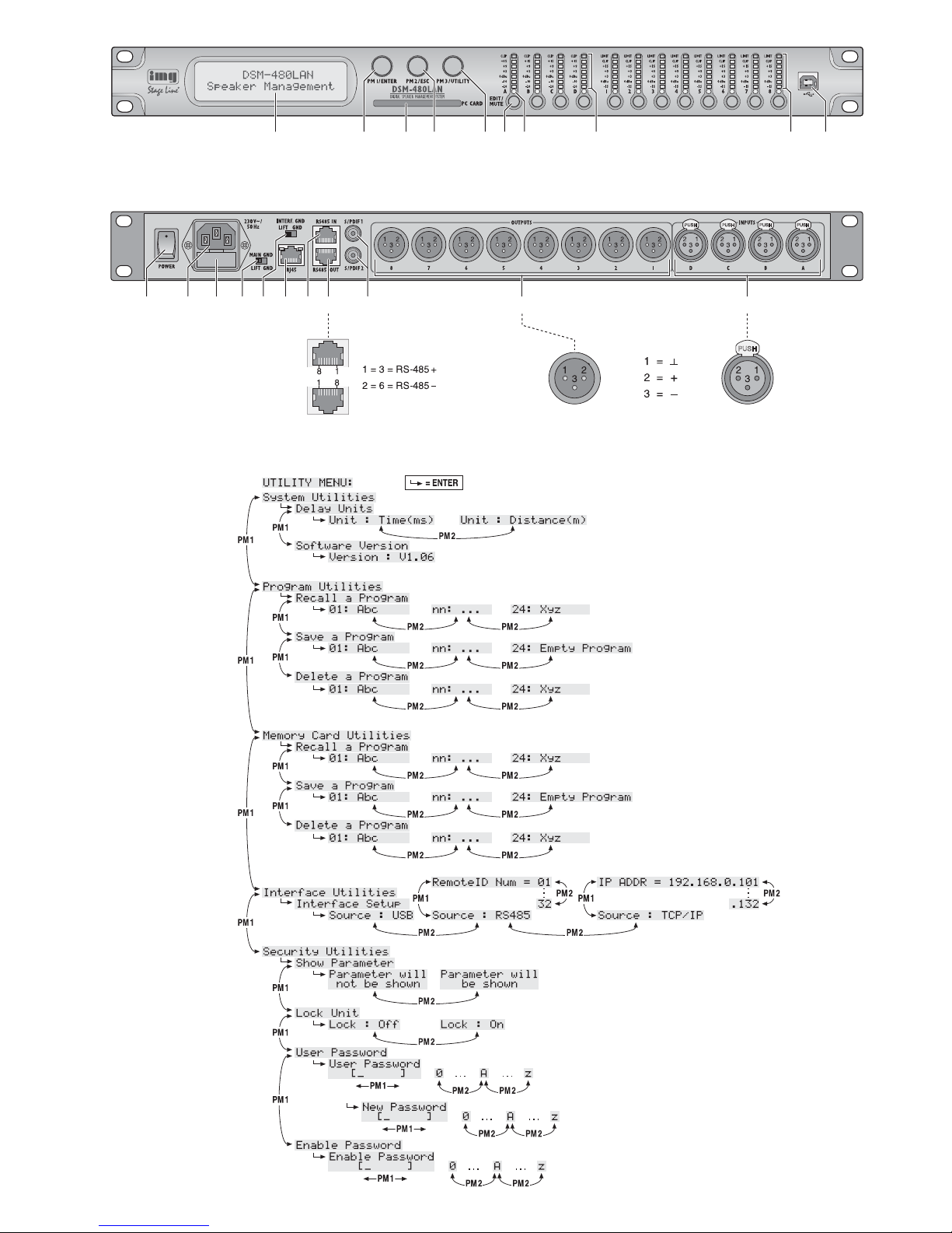
1 Übersicht der Bedienelemente
und Anschlüsse
1.1 Vorderseite
1 LC-Display
2 Drehknopf PM1/ ENTER zum Anwählen der
Menüpunkte, zur Wahl der Parameter und zur
Änderung von Werten;
zum Aufruf eines angewählten Untermenüs
und zur Bestätigung einer Eingabe den Knopf
drücken
3 Schlitz zur Aufnahme der Speicherchipkarte
(
Kap. 5.5.4)
4 Drehknopf PM2/ ESC zum Ändern von Ein-
stellungen, abhängig vom gewählten Untermenü punkt;
zum Abbruch einer Eingabe und Verlassen
eines Untermenüs den Knopf drücken
5 Drehknopf PM3/ UTILITY zum Ändern von
Einstellungen, abhängig vom gewählten Un termenü punkt;
zum Aufruf des Menüs für allgemeine Systemeinstellungen den Knopf drücken
6 Taste EDIT/ MUTE für die Anwahl oder Ab -
wahl eines Ein- bzw. Ausgangs zur Änderung
seiner Einstellungen und zu dessen Stummschaltung
Taste länger drücken (ca. 2 s):
Ein- bzw. Ausgang wird stummgeschaltet
oder der Ton wird wiedereingeschaltet [die
LED (7) leuchtet bei Stummschaltung rot]
Taste kurz drücken:
Ein- bzw. Ausgang wird an- oder abgewählt
[die LED (7) leuchtet bei angewähltem Einbzw. Ausgang blau]
Um Einstellungen für mehrere Ausgänge
gemeinsam durchzuführen, können zu einem
bereits angewählten Ausgang weitere angewählt werden. Diese können einzeln auch wieder abgewählt werden. Die Abwahl des zuerst
gewählten Ausgangs führt zur Abwahl aller
Ausgänge. Auf die gleiche Weise lässt sich
auch die Einstellung mehrerer Eingänge koppeln. Dabei werden nur die während der
Kopplung geänderten Parameter angeglichen. Alle individuellen Einstellungen der Einbzw. Ausgänge bleiben erhalten.
7 Status-LED EDIT/ MUTE, jeweils für die Ein-
gänge A bis D sowie für die Ausgänge 1 bis 8,
zeigt, dass der Ein- bzw. Ausgang für die
Änderung seiner Einstellungen angewählt ist
(leuchtet blau) oder/ und signalisiert die
Stummschaltung des Ein- bzw. Ausgangs
(leuchtet rot)
8 LED-Kette, jeweils für alle Eingänge, zur
Anzeige des Eingangssignalpegels;
leuchtet die LED CLIP, ist der Eingang übersteuert, in diesem Fall den Ausgangspegel
der Signalquelle entsprechend reduzieren
9 LED-Kette, jeweils für die Ausgänge 1 bis 8,
zur Anzeige des Signalpegels oder der Dynamikreduzierung, abhängig von der Einstellung
„Vu-Meter Mode“ des Ausgangs
Page 5
LIMIT
leuchtet, wenn der Pegelbegrenzer (Limiter)
oder der Kompressor aktiv ist und die Dynamik des Ausgangssignals verringert
„Vu-Meter Mode“ = „Level“
Die unteren fünf LEDs zeigen (der Bedruckung entsprechend) den absoluten Ausgangpegel. Leuchtet die LED CLIP, ist der Ausgang
übersteuert. In dem Fall den Pegel durch
Reduzierung der Verstärkung (Gain) für diesen Ausgang verringern. Die LED CLIP kann
auch aufleuchten, wenn bei extremen Filtereinstellungen in der Klangregelung eine Über steuerung auftritt.
„Vu-Meter“ = „Limiter Act“
Die unteren fünf LEDs zeigen, von oben nach
unten, die Pegelreduzierung durch den Limiter. Die LED CLIP leuchtet bei dieser Art der
Anzeige ständig und zeigt nicht die Übersteuerung des Ausgangs an.
„Vu-Meter“ = „RMS Cmp Act“
Die unteren fünf LEDs zeigen, von oben nach
unten, die Pegelreduzierung durch den Kompressor. Die LED CLIP leuchtet bei dieser Art
der Anzeige ständig und zeigt nicht die Übersteuerung des Ausgangs an.
10 USB-Buchse, Typ B, für den Anschluss eines
Computers zur Fernsteuerung des DSM480LAN
1.2 Rückseite
11 Netzschalter POWER
12 Netzbuchse zum Anschluss an eine Steck-
dose (230 V~/50Hz) über das beiliegende
Netzkabel
13 Halterung für die Netzsicherung;
eine durchgebrannte Sicherung nur durch
eine gleichen Typs ersetzen
14 Massetrennschalter MAIN GND für die Audio-
An schlüsse:
GND
Signalmasse mit Gehäusemasse verbunden
LIFT
Signalmasse und Gehäusemasse getrennt
(groundlift)
15 Massetrennschalter INTERF. GND für die
Schnittstellen zur Steuerung des Geräts über
einen Computer:
GND
Signalmasse mit Gehäusemasse verbunden
LIFT
Signalmasse und Gehäusemasse getrennt
(groundlift)
16 LAN-Anschluss RJ45 für den Anschluss
eines Computers zur Fernsteuerung des
DSM-480LAN; die beiden LEDs über der
Buchse signalisieren den Verbindungsaufbau
und den Datenverkehr
17 RJ45-Buchse RS485 IN für den Anschluss
eines Computers zur Fernsteuerung
18 RJ45-Buchse RS485 OUT für den Anschluss
eines weiteren zu steuernden Gerätes bei
Fernsteuerung durch einen Computer über
die Buchse RS485 IN (17)
19 Eingänge S/ PDIF 1 und S/ PDIF 2 als Cinch-
Buchsen, zum An schluss digitaler Audiosignalquellen
20 symmetrisch beschaltete Audiosignal-Aus-
gänge OUTPUT 1 bis 8 als XLR-Buchsen
21 symmetrisch beschaltete Audiosignal-Ein-
gänge INPUT A bis D als XLR-Buchsen zum
Anschluss analoger Signalquellen
2 Hinweise für den
sicheren Gebrauch
Das Gerät entspricht allen relevanten Richt linien
der EU und ist deshalb mit gekennzeichnet.
Beachten Sie auch unbedingt folgende Punkte:
Das Gerät ist nur zur Verwendung im Innen bereich geeignet. Schützen Sie es vor Tropfund Spritzwas ser, hoher Luftfeuchtigkeit und
Hitze (zulässiger Einsatztemperaturbereich
0 – 40°C).
Stellen Sie keine mit Flüssigkeit gefüllten Ge fäße, z. B. Trinkgläser, auf das Gerät.
Die im Gerät entstehende Wärme muss durch
Luftzirkulation abgegeben werden. Decken
Sie darum die Lüftungsöffnungen nicht ab.
Nehmen Sie das Gerät nicht in Betrieb und
ziehen Sie sofort den Netzstecker aus der
Steckdose,
1. wenn sichtbare Schäden am Gerät oder am
Netzkabel vorhanden sind,
2. wenn nach einem Sturz oder Ähnlichem der
Verdacht auf einen Defekt besteht,
3. wenn Funktionsstörungen auftreten.
Geben Sie das Gerät in jedem Fall zur Reparatur in eine Fachwerkstatt.
Ziehen Sie den Netzstecker nie am Kabel aus
der Steckdose, fassen Sie immer am Stecker
an.
Verwenden Sie für die Reinigung nur ein trockenes, weiches Tuch, niemals Wasser oder
Chemikalien.
Wird das Gerät zweckentfremdet, nicht richtig
angeschlossen, falsch be dient oder nicht
fachgerecht repariert, kann keine Haftung für
daraus resultierende Sach- oder Personenschäden und keine Garantie für das Gerät
übernommen werden. Ebenso kann keine
Haftung für durch Fehlbedienung oder durch
einen Defekt entstandene Datenverluste und
deren Folgeschäden übernommen werden.
3 Einsatzmöglichkeiten
Das DSM-480LAN ist ein digitaler Signalprozessor mit vier Eingängen (analog oder digital) und
acht Ausgängen. Es ist als Bindeglied zwischen
einem Mischpult und den Leistungsverstärkern
einer Beschallungsanlage vorgesehen und vereinigt dort die Funktionen von Frequenz weichen, Equalizern, Delays, Kompressoren
und Limitern. Durch seine vielseitigen Konfigura-
tionsmöglichkeiten kann es in den unterschiedlichsten Lautsprecherkonstellationen eingesetzt
werden.
Es können 24 Konfigurationen jeweils im
Gerät und auf der mitgelieferte Speicherchipkarte gespeichert und bei Bedarf wieder abgerufen werden. Über die beiliegende Software lässt
sich das DSM-480LAN zudem bequem über
einen Computer fernsteuern. Der Anschluss des
Computers erfolgt über die USB-Schnittstelle,
Ethernet oder einen RS-485-Datenbus. Dabei
können über Ethernet oder RS-485 bis zu 32
Geräte gesteuert werden.
Einstellbar je Eingangskanal sind:
– Gain [
-
18...+18 dB]
– Signalquelle: Analog-Eingang, Digital-Ein-
gang oder ein intern generiertes Testsignal
(Weißes Rauschen/ Rosa Rauschen)
– Noise-Gate
– parametrischer Equalizer mit 5 Filtern
(jeweils 17 Filtertypen zur Auswahl)
– Delay [max. 849 ms], als Zeit (ms) oder Ent-
fernung (m) einzugeben
– Stummschaltung
Einstellbar je Ausgangskanal sind:
– Zuordnung zu einem Eingangssignal oder
dem Mischsignal mehrerer Eingänge
– Hochpassfilter und Tiefpassfilter mit 17 Filter-
charakteristiken unterschiedlicher Flanken -
steilheit zum Erstellen von Frequenzweichen
– parametrischer Equalizer mit 7 Filtern
(jeweils 17 Filtertypen zur Auswahl)
– Delay [max. 849 ms], als Zeit (ms) und Ent-
fernung (m) einzugeben
– Kompressor
– Gain [
-
18...+18 dB]
– Peak-Limiter [
-
10...+20 dBu]
– Phasenumkehr
– Stummschaltung
4 Gerät aufstellen und
anschließen
Das DSM-480LAN ist für die Montage in einem
Rack (482 mm / 19″) vorgesehen, kann aber
auch als frei stehendes Gerät verwendet werden. Für den Einbau in ein Rack wird 1 HE benötigt (HE = Höheneinheit = 44,45 mm).
Vor dem Anschließen oder Ändern bestehender
Anschlüsse das DSM-480LAN und die anzuschließenden Geräte ausschalten.
4.1 Signalquellen
Analoge Signalquellen mit Line-Pegel, z. B. den
Ausgang eines Vorverstärkers oder eines
Mischpults, an die XLR-Buchsen INPUTS A bis
D (21) anschließen. Die Buchsen sind für symmetrische Signale beschaltet; die Kontaktbelegung ist in Abbildung 2 dargestellt. Für den
Anschluss von Quellen mit asymmetrischen Signalen Adapter verwenden, bei denen die XLRKontakte 1 und 3 gebrückt sind.
Digitale Signalquellen mit einem Ausgang
nach dem S/PDIF-Standard an die Buchsen
S/PDIF (19) anschließen. Analoge und digitale
Eingangssignale können pro Eingangskanal nur
alternativ verarbeitet werden (Signalquelle wählen,
Kap. 5.3.2).
Soll das Gerät endgültig aus dem Be trieb genommen werden, übergeben
Sie es zur umweltgerechten Entsorgung einem örtlichen Recyclingbetrieb.
WARNUNG Das Gerät wird mit lebensge fähr -
licher Netzspannung versorgt.
Nehmen Sie deshalb niemals
selbst Eingriffe am Gerät vor und
stecken Sie nichts in die Lüftungsschlitze. Es besteht die Gefahr
eines elektrischen Schlages.
D
A
CH
5
Page 6
4.2 Verstärker
An die XLR-Anschlüsse OUTPUTS (20) die
Leistungsverstärker oder Geräte zur weiteren
Signalverarbeitung anschließen.
4.3 Computer
Zur Fernsteuerung des DSM-480LAN über
einen Computer diesen über ein USB-Kabel an
die Buchse (10) anschließen.
Alternativ kann das Gerät über die RS-485Schnittstelle oder Ethernet gesteuert werden.
Für die Steuerung über RS-485 den RS-485Ausgang des Computers mit der Buchse RS485 IN (17) verbinden; die Kontaktbelegung ist
in Abbildung 2 dargestellt. Die Ausgangsbuchse
RS-485 OUT (18) kann jeweils mit der Buchse
RS-485 IN eines weiteren DSM-480LAN verbunden werden. Auf diese Weise können bis zu
32 zu steuernde Geräte in einer Kette angeschlossen werden. Werden mehrere Geräte verbunden und längere Steuerleitungen verwendet,
sollte der Steuerausgang des letzten Gerätes
der Kette zur Vermeidung von Störungen bei der
Signalübertragung mit einem Abschlusswiderstand versehen werden (120-Ω-Widerstand zwischen Pin 1 und 2 des Anschlusses).
Zur Fernsteuerung des Gerätes per Ethernet (TCP/ IP) kann das DSM-480LAN über seine
Anschlussbuchse RJ45 (16) mit einem einzelnen Computer, einem lokalen Computernetzwerk oder, z. B. über einen Router, mit größeren
Computernetzwerken verbunden werden. Es
lassen sich bis zu 32 Geräte in einem Netz
adressieren. Für die korrekte Einrichtung sind
unbedingt Netzwerktechnik-Kenntnisse erforderlich.
Hinweis: Bei einer direkten Ethernet-Verbindung mit
einem Computer wird ein Crossover-Kabel benötigt.
4.4 Netzanschluss
Das mitgelieferte Netzkabel mit der Netzbuchse
(12) verbinden und den Netzstecker in eine
Steckdose (230 V~/50Hz) stecken.
5 Bedienung
5.1 Ein-/Ausschalten
Vor dem Einschalten der angeschlossenen Leistungsverstärker das DSM-480LAN mit dem
Schalter POWER (11) einschalten. Die Einstellungen des letzten Betriebs werden geladen und
der Name der zuletzt aus dem Speicher geladenen Konfiguration wird angezeigt.
Nach dem Gebrauch das Gerät mit dem Schalter POWER wieder ausschalten. Dabei bleiben
alle Einstellungen erhalten.
5.2 Systemeinstellungen
(System Utilities)
Die Einstellung des DSM-480LAN erfolgt über
ein Menü im Display (1). Der Aufruf des Menüs
für die allgemeinen Systemeinstellungen erfolgt
durch Drücken des Knopfes UTILITY (5), die
Menüs für die Einstellung der Ein- und Ausgänge werden durch die Anwahl des Ein- oder
Ausgangs mit der entsprechenden Taste EDIT/
MUTE (6) aufgerufen. Die Navigation durch das
Menü und die Änderung der Einstellungen
geschieht durch Drücken der Knöpfe ENTER
(2), ESC (4) und Drehen des Knopfes PM1 (2).
Dabei lässt sich ein Menüpunkt mit dem Drehknopf PM1/ ENTER anwählen; das Drücken dieses Knopfes ruft das Untermenü auf oder bestätigt eine Eingabe während das Drücken des
Knopfes ESC in die höhere Menüebene zurückführt, ohne eine Änderung zu übernehmen. Die
Änderung von Parametern erfolgt durch Drehen
der beiden Knöpfe PM2 (4) und PM3 (5). Steht
auf dem Display hinter einer Option ein
*
, ent-
spricht diese der aktuellen Einstellung.
Eine Übersicht des Menüs „UTILITY“ ist in
Abbildung 3 auf Seite 3 zu sehen.
5.2.1 Einheit für Signalverzögerung
Die Signale aller Ein- und Ausgänge können
individuell verzögert werden. Dies ist z. B. sinnvoll, wenn Lautsprecher einen unterschiedlichen
Abstand zu den Hörern haben. Um die Verzögerung durch die Schalllaufzeit auszugleichen,
wird das Signal des näheren Lautsprechers
soweit verzögert, dass es nicht vor dem des entfernteren Lautsprechers beim Hörer eintrifft.
Damit die Schalllaufzeit nicht vom Benutzer
berechnet werden muss, kann die Verzögerung
wahlweise nicht nur als Zeit, sondern auch als
Abstand eingegeben werden. Das Gerät rechnet
mit einer Schallgeschwindigkeit von 340 m/s.
1) Durch Drücken des Knopfes UTILITY (5) das
Menü aufrufen.
Es wird
System Utilities
angezeigt.
2) Zum Aufruf dieses Untermenüs den Knopf
ENTER (2) drücken.
Es wird
Delay Units
angezeigt.
3) Zum Aufruf dieses Untermenüs den Knopf
ENTER (2) drücken.
4) Mit dem Drehknopf PM2 (4) wählen, ob die
Verzögerungswerte als Zeit (
Unit : Time
(ms)
) oder als Abstand (
Unit : Dis-
tance(m)
) eingegeben werden sollen und
die Auswahl durch Drücken des Knopfes
ENTER bestätigen.
5) Zum Verlassen des Menüs zweimal den
Knopf ESC (4) drücken. Es kann auch direkt
mit einer der Tasten EDIT/ MUTE (6) zur Einstellung eines Ein- oder Ausgangs gewechselt werden.
5.2.2 Firmware-Version anzeigen
Zum Anzeigen der Version der Firmware
(Betriebssoftware des DSM-480LAN):
1) Durch Drücken des Knopfes UTILITY (5) das
Menü aufrufen.
Es wird
System Utilities
angezeigt.
2) Zum Aufruf dieses Untermenüs den Knopf
ENTER (2) drücken.
Es wird
Delay Units
angezeigt.
3) Mit dem Drehknopf PM1/ ENTER (2) den
Menüpunkt
Software Version
anwählen und durch Drücken des Knopfes bestätigen.
Die Versionsnummer wird angezeigt, z. B.
Version : V1.06
4) Zum Verlassen des Menüs dreimal den
Knopf ESC (4) drücken. Es kann auch direkt
mit einer der Tasten EDIT/ MUTE (6) zur Einstellung eines Ein- oder Ausgangs gewechselt werden.
5.3 Eingänge konfigurieren
Die Signale der Eingänge lassen sich bereits
bearbeiten, bevor sie auf die Ausgänge verteilt
werden. Dabei durchlaufen sie die in Abbildung
4 gezeigte Verarbeitungskette.
5.3.1 Eingang stummschalten und für die
Einstellung anwählen
Jeder Eingang lässt sich mit der Taste EDIT/
MUTE (6) unterhalb seiner Pegel-Anzeige
sowohl stummschalten als auch für die Änderung von Einstellungen anwählen.
Taste länger drücken (ca. 2 s):
Der Eingang wird stummgeschaltet oder der
Ton wird wiedereingeschaltet. Bei stummgeschaltetem Eingang leuchtet die LED (7) über
der Taste rot.
Taste kurz drücken:
Der Eingang wird an- oder abgewählt. Bei
angewähltem Eingang leuchtet die LED über
der Taste blau.
Um Einstellungen für mehrere Eingänge
gemeinsam durchzuführen, können zu einem
bereits angewählten Eingang weitere angewählt werden. Diese lassen sich auch wieder
abwählen. Die Abwahl des zuerst gewählten
Eingangs führt zur Abwahl aller Eingänge.
Dabei werden nur die während der Kopplung
geänderten Parameter angeglichen. Alle individuellen Einstellungen der Eingänge bleiben
erhalten.
Mit der Anwahl eines Eingangs wird im Display
(1) der zuletzt für diesen Eingang aufgerufene
Menüpunkt im Menü der Eingangseinstellungen
angezeigt (
Abb. 5). Die Anwahl der Menüpunkte und die Änderung der Einstellungen werden mithilfe der Knöpfe PM1/ ENTER (2), PM2/
ESC (4) und PM3 (5) durchgeführt.
5.3.2 Signalquelle wählen
Das Gerät verfügt über Eingänge für analoge
(21) und digitale (19) Signale, die jeweils alternativ genutzt werden können. Zu Testzwecken
lässt sich anstelle eines Eingangssignals ein im
Gerät generiertes Signal (Weißes oder Rosa
Rauschen) auswählen.
1) Einen Eingang mit seiner Taste EDIT/ MUTE
(6) anwählen.
2) Mit dem Drehknopf PM1/ ENTER den Menü-
punkt
Source
anwählen und durch Drücken des Knopfes bestätigen. Die aktuelle
Einstellung wird angezeigt (z. B.
ƊSource
= Analog
).
3) Mit dem Drehknopf PM2 die gewünschte Signalquelle einstellen. Eine Änderung wird
sofort übernommen.
Vorsicht beim Umschalten auf die Testsignale! Sie nutzen die volle Dynamik und können eventuell erheblich lauter als das Signal
am Eingang sein.
Analog
Analog-Eingang
Digital
Digital-Eingang
Eingang A = S/PDIF 1, Kanal 1
Eingang B = S/PDIF 1, Kanal 2
Eingang C = S/PDIF 2, Kanal 1
Eingang D = S/PDIF 2, Kanal 2
White Noise
Weißes Rauschen
Pink Noise
Rosa Rauschen
4) Durch Drücken des Knopfes ESC das Untermenü wieder verlassen.
5.3.3 Noise-Gate
Für jeden Eingang kann ein Noise-Gate eingeschaltet werden. Damit werden leise Störgeräusche, deren Pegel unterhalb des eingestellten
Schwellwertes liegen, in Signalpausen unterdrückt.
VORSICHT Das DSM-480LAN bietet sehr fle-
xible Konfigurationsmöglichkeiten.
Es kann z. B. ein Ausgang, der für
die Ansteuerung eines Hochtonlautsprechers konfiguriert ist, in
einer anderen Konfiguration zum
Tieftonausgang werden.
Um eine mögliche Überlastung der Lautsprecher zu vermeiden, überprüfen Sie darum
unbedingt vor dem Einschalten der Leistungsverstärker, ob die geladene Konfiguration des
DSM-480LAN mit der angeschlossenen Lautsprecherkonstellation übereinstimmt.
D
A
CH
6
Page 7
1) Einen Eingang mit seiner Taste EDIT/ MUTE
(6) anwählen.
2) Mit dem Drehknopf PM1/ ENTER den Menüpunkt
N Gate
anwählen und durch Drücken
des Knopfes bestätigen. Die aktuelle Einstellung wird angezeigt
(z. B.
ƊNoise Gate = Off
).
3) Mit dem Drehknopf PM2 die Rauschunterdrückung ein- (
On
) oder ausschalten (
Off
).
Eine Änderung wird sofort übernommen.
4) Durch Drücken des Knopfes ESC das Untermenü wieder verlassen.
Hinweis: Die Betriebsparameter Schwellwert
(Threshold), Ansprechzeit (Attack) und Rückstellzeit (Release) für das Noise-Gate können
nur per Computer über das mitgelieferte Steuerprogramm geändert werden (
Kap. 6.4.4.6).
5.3.4 Verstärkung einstellen (Gain)
Der Pegel eines Eingangssignals kann über die
Einstellung der Verstärkung im Bereich
-
18 dB
bis +18 dB angepasst werden.
1) Einen Eingang mit seiner Taste EDIT/ MUTE
(6) anwählen.
2) Mit dem Drehknopf PM1/ ENTER den Menüpunkt
Gain
anwählen und durch Drücken
des Knopfes bestätigen. Die aktuelle Einstellung wird angezeigt
(z. B.
ƊGain = 0.0dB
).
3) Mit dem Drehknopf PM2 die gewünschte Verstärkung einstellen. Eine Änderung wird
sofort übernommen.
4) Durch Drücken des Knopfes ESC das Untermenü wieder verlassen.
5.3.5 Verzögerung einstellen (Delay)
Jedes Eingangssignal kann bis zu 848 ms verzögert werden. Dadurch können z. B. Schalllaufzeitunterschiede bei verschiedenen Lautsprecherabständen ausgeglichen werden.
1) Einen Eingang mit seiner Taste EDIT/ MUTE
(6) anwählen.
2) Mit dem Drehknopf PM1/ ENTER den Menüpunkt
Delay
anwählen und durch Drücken
des Knopfes bestätigen.
Die aktuelle Einstellung wird angezeigt, z. B.
ƊDelay = 100.1040ms
Dabei hängt es vom Untermenü „Delay Units“
im Menü für die allgemeinen Systemeinstellungen ab, ob die Verzögerung als Zeit (ms)
oder als Abstand (
m
) angegeben ist (Kap.
5.2.1).
3) Mit den Drehknöpfen PM2 [grob] und PM3
[fein] die gewünschte Verzögerung einstellen. Eine Änderung wird sofort übernommen.
4) Durch Drücken des Knopfes ESC das Untermenü wieder verlassen.
5.3.6 Klangregelung einstellen (EQ 1 – 5)
Jeder Eingang verfügt über 5 unabhängig einstellbare Filter. Über die Funktion EQ Bypass
können sämtliche Filter des Eingangs umgangen werden.
1) Einen Eingang mit seiner Taste EDIT/ MUTE
(6) anwählen.
2) Mit dem Drehknopf PM1/ ENTER den Menüpunkt
EQ Byp
anwählen und durch Drücken
des Knopfes bestätigen. Die aktuelle Einstellung wird angezeigt.
3) Mit dem Drehknopf PM2 wählen, ob die Filter
dieses Kanals wirksam sein sollen (
ƊEQ
Bypass = Off
) oder umgangen werden
sollen (
ƊEQ Bypass = On
). Eine Ände-
rung wird sofort übernommen.
4) Durch Drücken des Knopfes ESC das Untermenü wieder verlassen.
Für jedes der 5 Filter (
EQ-1
bis
EQ-5
) können
die folgenden Parameter eingestellt werden.
Voraussetzung für die Änderung dieser Parameter ist die Deaktivierung der vorangehend be schriebenen Funktion (
EQ Bypass = Off
).
Anderenfalls erscheint beim Aufruf einer der folgenden Untermenüpunkte ein Hinweis darauf.
5.3.6.1 Bypass
Mit dieser Funktion kann nur das gewählte Filter
umgangen werden.
1) Einen Eingang mit seiner Taste EDIT/ MUTE
(6) anwählen.
2) Mit dem Drehknopf PM1/ ENTER das ge -
wünschte Filter (
EQ-1
bis
EQ-5
) anwählen
und durch Drücken des Knopfes bestätigen.
Die aktuelle Einstellung wird angezeigt, z. B.
ƊByp=Off
3) Mit dem Drehknopf PM2 wählen, ob das
gewählte Filter wirksam sein (
ƊByp=Off
)
oder umgangen werden soll (
ƊByp=On
).
Eine Änderung wird sofort übernommen.
4) Durch Drücken des Knopfes ESC das Untermenü wieder verlassen.
Bei aktiver Bypass-Funktion (
Byp=On
) können
die anderen Parameter dieses Filters nicht
geändert werden.
5.3.6.2 Filtertyp wählen
Es stehen 17 Filtertypen mit unterschiedlichen
Charakteristiken zur Auswahl. Zum Ändern des
Filtertyps:
1) Einen Eingang mit seiner Taste EDIT/ MUTE
(6) anwählen.
2) Mit dem Drehknopf PM1/ ENTER das ge -
wünschte Filter (
EQ-1
bis
EQ-5
) anwählen
und durch Drücken des Knopfes bestätigen.
Die aktuelle Einstellung wird angezeigt, z. B.
Input-A EQ-1 Ƅ
ƊByp=Off Type=Peaking_Eq
Zusätzlich zum Filtertyp (
Peaking_Eq
)
wird oben rechts ein Symbol für dessen Charakteristik angezeigt (
Ƅ
).
3) Mit dem Drehknopf PM3 den Filtertyp wählen. Eine Änderung wird sofort übernommen.
Folgende Filtertypen stehen zur Auswahl:
Ƅ Peaking_Eq
(Peaking Equalizer)
Filter mit Glockencharakteristik mit einstellbarer Verstärkung/Abschwächung, Mittenfrequenz und Güte
ƃ Hi-Shelv_1
(High Shelving Filter 1)
Höhenfilter erster Ordnung mit Kuhschwanz charakteristik
Bei der einstellbaren Grenz frequenz liegt der
Pegel 3 dB unterhalb/ oberhalb der eingestellten Verstärkung/ Ab schwächung; die Steilheit
beträgt 6 dB/ Oktave.
D
A
CH
7
⑤
Menüstruktur für die Einstellung eines Eingangskanals
④
Blockdiagramm eines Eingangskanals
Page 8

ƃ Hi-Shelv_2
(High Shelving Filter 2)
Höhenfilter zweiter Ordnung mit Kuhschwanz charakteristik
Bei der einstellbaren Grenz frequenz liegt der
Pegel 3 dB unterhalb/ oberhalb der eingestellten Verstärkung/ Ab schwächung; die Steilheit
beträgt 12 dB/ Oktave.
ƃ Hi-Shelv_Q
(High Shelving Filter Q)
Symmetrisches Höhenfilter mit Kuhschwanz charakteristik
Bei der einstellbaren Grenz frequenz liegt der
Pegel auf der Hälfte der eingestellten Verstärkung/ Ab schwächung; die Steilheit hängt
von der einstellbaren Güte ab.
Ƃ Lo-Shelv_1
(Low Shelving Filter 1)
Tiefenfilter erster Ordnung mit Kuhschwanz charakteristik
Bei der einstellbaren Grenz frequenz liegt der
Pegel 3 dB unterhalb/ oberhalb der eingestellten Verstärkung/ Ab schwächung; die Steilheit
beträgt 6 dB/ Oktave.
Ƃ Lo-Shelv_2
(Low Shelving Filter 2)
Tiefenfilter zweiter Ordnung mit Kuhschwanz charakteristik
Bei der einstellbaren Grenz frequenz liegt der
Pegel 3 dB unterhalb/ oberhalb der eingestellten Verstärkung/ Ab schwächung; die Steilheit
beträgt 12 dB/ Oktave.
Ƃ Lo-Shelv_Q
(Low Shelving Filter Q)
Symmetrisches Tiefenfilter mit Kuhschwanz charakteristik
Bei der einstellbaren Grenz frequenz liegt der
Pegel auf der Hälfte der eingestellten Verstärkung/ Ab schwächung; die Steilheit hängt
von der einstellbaren Güte ab.
Ɓ Low Pass_1
(Low Pass Filter 1)
Tiefpassfilter erster Ordnung mit einer Ab schwächung von 3 dB bei der Grenzfrequenz
und einer Steilheit von 6 dB/ Oktave.
Ɓ Low Pass_2
(Low Pass Filter 2)
Tiefpassfilter zweiter Ordnung mit einer Ab schwächung von 3 dB bei der Grenzfrequenz
und einer Steilheit von 12 dB/ Oktave.
Ɓ Low Pass_Q
(Low Pass Filter Q)
Tiefpassfilter mit variabler Güte.
ƀ HighPass_1
(High Pass Filter 1)
Hochpassfilter erster Ordnung mit einer Ab schwächung von 3 dB bei der Grenzfrequenz
und einer Steilheit von 6 dB/ Oktave.
ƀ HighPass_2
(High Pass Filter 2)
Hochpassfilter zweiter Ordnung mit einer Ab schwächung von 3 dB bei der Grenzfrequenz
und einer Steilheit von 12 dB/ Oktave.
ƀ HighPass_Q
(High Pass Filter Q)
Hochpassfilter mit variabler Güte.
ƅ All Pass_1
(All Pass Filter 1)
Allpassfilter mit konstantem Amplituden-Frequenzgang und einer Phasendrehung von
90° bei der einstellbaren Frequenz.
ƅ All Pass_2
(All Pass Filter 2)
Allpassfilter mit konstantem Amplituden-Frequenzgang und einer Phasendrehung von
180° bei der einstellbaren Frequenz.
Ƅ Band Pass
(Band Pass Filter)
Bandpassfilter mit einem Durchlassbereich
um die einstellbare Frequenz. Die Bandbreite
wird durch die einstellbare Güte bestimmt.
Ƅ Notch Filt
(Notch Filter)
Kerbfilter zur schmalbandigen Absenkung
des Pegels um die einstellbare Frequenz.
Der Grad der Absenkung wird durch die einstellbare Güte bestimmt.
5.3.6.3 Filterparameter ändern
1) Einen Eingang mit seiner Taste EDIT/ MUTE
(6) anwählen.
2) Mit dem Drehknopf PM1/ ENTER das ge wünschte Filter (
EQ-1
bis
EQ-5
) anwählen
und durch Drücken des Knopfes bestätigen.
Die aktuelle Einstellung wird angezeigt, z. B.
Input-A EQ-1 Ƅ
ƊByp=Off Type=Peaking_Eq
3) Den Knopf ENTER drücken. Die aktuellen
Filterparameter werden jetzt angezeigt, z. B.
Ɗ 1000Hz +11.5dB Q=1.1
d. h. Mittenfrequenz = 1000 Hz,
Verstärkung = 11,5 dB, Filtergüte = 1,1
Hinweis: Die Verfügbarkeit eines Parameters
hängt vom gewählten Filtertyp ab.
4) Mit dem Drehknopf PM1/ ENTER die Frequenz einstellen. Eine Änderung wird sofort
übernommen.
Um größere Frequenzänderungen schneller
durchführen zu können, den Knopf drücken.
In der unteren Zeile des Displays erscheint
jetzt z. B.:
ƊEdit Freq = 1000Hz
Die Frequenz kann jetzt gezielt mit den
Drehknöpfen PM1 in 100-Hz-Schritten, PM2
in 10-Hz-Schritten und PM3 in 1-HzSchritten geändert werden. Zur Rückkehr auf
die höhere Menüebene den Knopf ESC drücken.
5) Mit dem Drehknopf PM2 die Verstärkung/ Ab schwächung einstellen.
6) Mit dem Drehknopf PM3 die Filtergüte einstellen. Eine Änderung wird sofort übernommen.
Zur Rückkehr in die nächsthöhere Menüebene
den Knopf ESC drücken. Zum Verlassen des
Einstellmenüs den Knopf ESC wiederholt drücken oder den zuerst angewählten Eingang wieder abwählen.
5.4 Ausgänge konfigurieren
Die Signale aller Ausgänge durchlaufen die in
Abb. 6 gezeigte Verarbeitungskette.
5.4.1 Ausgang stummschalten und für die
Einstellung anwählen
Jeder Ausgang lässt sich mit der Taste EDIT/
MUTE (6) unterhalb seiner Pegel-Anzeige
sowohl stummschalten als auch für die Änderung von Einstellungen anwählen.
Taste länger drücken (ca. 2 s):
Der Ausgang wird stummgeschaltet oder der
Ton wird wiedereingeschaltet. Bei stummgeschaltetem Ausgang leuchtet die LED (7) über
der Taste rot.
Taste kurz drücken:
Der Ausgang wird an- oder abgewählt. Bei
angewähltem Ausgang leuchtet die LED über
der Taste blau.
Um Einstellungen für mehrere Ausgänge
gemeinsam durchzuführen, können zu einem
bereits angewählten Ausgang weitere angewählt werden. Diese lassen sich auch wieder
abwählen. Die Abwahl des zuerst gewählten
Ausgangs führt zur Abwahl aller Ausgänge.
Es werden nur die während der Kopplung
geänderten Parameter angeglichen. Alle indi-
viduellen Einstellungen der Ausgänge bleiben
erhalten.
Mit der Anwahl eines Ausgangs wird im Display
(1) der zuletzt für diesen Ausgang aufgerufene
Menüpunkt im Menü der Ausgangseinstellungen
angezeigt (
Abb. 7). Die Anwahl der Menüpunkte und die Änderung der Einstellungen werden mithilfe der Knöpfe PM1/ ENTER (2), PM2/
ESC (4) und PM3 (5) durchgeführt.
5.4.2 Name ändern
Die Namen der Ausgänge sind ab Werk auf
„Out-1“ bis „Out-8“ voreingestellt. Diese Namen
können für jede Konfiguration geändert werden,
um z. B. auf den Ort oder die Funktion der Lautsprecher hinzuweisen.
1) Einen Ausgang mit seiner Taste EDIT/ MUTE
(6) anwählen.
2) Mit dem Drehknopf PM1/ ENTER den Menü-
punkt
Name
anwählen und durch Drücken
des Knopfes bestätigen. Der aktuelle Name
wird angezeigt, z. B.
ƊName = Low-A
Das erste Zeichen des Namens blinkt.
3) Mit dem Drehknopf PM2 das blinkende Zeichen ändern. Mit dem Drehknopf PM1 jeweils
das nächste zu ändernde Zeichen wählen.
Der Name eines Ausgangs kann aus max.
6 Zeichen bestehen.
4) Zum Übernehmen der Änderung den Knopf
ENTER drücken. Soll der alte Name beibehalten werden, den Knopf ESC drücken.
Hinweis: Sind mehrere Ausgänge angewählt,
wird bei dieser Funktion nur der Name des
zuerst gewählten Ausgangs geändert.
5.4.3 Eingangssignal wählen (Source)
Jedem Ausgang kann eine beliebige Kombination
der vier Eingangskanäle zugewiesen werden.
Dabei lässt sich jedes der Eingangssignale im
Mischsignal für diesen Ausgang bis zu 30 dB
dämpfen.
1) Einen Ausgang mit seiner Taste EDIT/ MUTE
(6) anwählen.
2) Mit dem Drehknopf PM1/ ENTER den Menüpunkt
Source
anwählen. Die aktuelle
Zuordnung wird angezeigt, z. B.
A:00 B:--- C:-30 D:---
d. h. hier werden dem Ausgang die Signale
der Eingangskanäle A und C zugeführt, dabei
ist der Pegel von C um 30 dB reduziert.
3) Zum Ändern der Einstellung den Knopf
ENTER drücken. Das Display zeigt jetzt:
ƊIn-A Mute=Off Val=00
4) Mit dem Drehknopf PM1/ ENTER jeweils den
Eingangskanal wählen (
In-A
bis
In-D
).
Mit dem Drehknopf PM2 wählen, ob das
Signal dieses Eingangs auf den Ausgang
geleitet werden soll (
Mute=Off
) oder nicht
(
Mute=On
).
Mit dem Drehknopf PM3 kann das Signal
(nur für diesen Ausgang) gedämpft werden.
Dabei sind Einstellungen von
Val=00
(0 dB
Verstärkung, d. h. keine Dämpfung) bis
Val=-30
(d. h. 30 dB Dämpfung) möglich.
Eine Änderung wird sofort übernommen.
5) Durch Drücken des Knopfes ESC das Untermenü wieder verlassen.
D
A
CH
8
⑥
Blockdiagramm eines Ausgangskanals
Page 9
5.4.4 Verzögerung einstellen (Delay)
Jedes Ausgangssignal kann bis zu 848 ms ver-
zögert werden. Dadurch können z. B. Schalllaufzeitunterschiede bei verschiedenen Lautsprecherabständen ausgeglichen werden. Ist in dem
zugewiesenen Eingangssignal bereits eine Verzögerung eingestellt, addieren sich die Zeiten.
1) Einen Ausgang mit seiner Taste EDIT/ MUTE
(6) anwählen.
2) Mit dem Drehknopf PM1/ ENTER den Menüpunkt
Delay
anwählen und durch Drücken
des Knopfes bestätigen.
Die aktuelle Einstellung wird angezeigt, z. B.
ƊDelay = 100.1040ms
Dabei hängt es vom Untermenü „Delay Units“
im Menü für die allgemeinen Systemeinstellungen ab, ob die Verzögerung als Zeit (ms)
oder als Abstand (m) angegeben ist (Kap.
5.2.1).
3) Mit den Drehknöpfen PM2 [grob] und PM3
[fein] die gewünschte Verzögerung einstellen. Eine Änderung wird sofort übernommen.
4) Durch Drücken des Knopfes ESC das Untermenü wieder verlassen.
5.4.5 Hochpass- und Tiefpassfilter
Jeder Ausgang verfügt über Hochpass- und Tiefpassfilter, die in Kombination primär die Funktion
einer Frequenzweiche (zur frequenzabhängigen
Aufteilung eines Eingangssignals auf zwei oder
mehrere Ausgangskanäle) erfüllen.
1) Einen Ausgang mit seiner Taste EDIT/ MUTE
(6) anwählen.
2) Zum Einstellen des Hochpassfilters mit dem
Drehknopf PM1/ ENTER den Menüpunkt
HPF ƀ
anwählen und durch Drücken des
Knopfes bestätigen.
Die aktuelle Einstellung wird angezeigt, z. B.
ƊBessel_2nd F = 100Hz
d. h. Filtercharakteristik: Bessel, 2. Ordnung,
Grenzfrequenz = 100 Hz
3) Mit dem Drehknopf PM2 eine von 17 Filtercharakteristiken wählen oder
Bypass
,
wenn das Filter umgangen werden soll. Eine
Änderung wird sofort übernommen.
Folgende Filtercharakteristiken stehen zur
Auswahl:
Buttw_1st
Butterworth-Filter erster Ordnung mit einer
Flankensteilheit von 6 dB/ Oktave
Buttw_2nd
Butterworth-Filter zweiter Ordnung mit einer
Flankensteilheit von 12 dB/ Oktave
LRiley_2nd
Linkwitz-Riley-Filter zweiter Ordnung mit
einer Flankensteilheit von 12 dB/ Oktave
Bessel_2nd
Bessel-Filter zweiter Ordnung mit einer Flankensteilheit von 12 dB/ Oktave
Buttw_3rd
Butterworth-Filter dritter Ordnung mit einer
Flankensteilheit von 18 dB/ Oktave
Buttw_4th
Butterworth-Filter vierter Ordnung mit einer
Flankensteilheit von 24 dB/ Oktave
LRiley_4th
Linkwitz-Riley-Filter vierter Ordnung mit einer
Flankensteilheit von 24 dB/ Oktave
Bessel_4th
Bessel-Filter vierter Ordnung mit einer Flankensteilheit von 24 dB/ Oktave
LRiley_6th
Linkwitz-Riley-Filter sechster Ordnung mit
einer Flankensteilheit von 36 dB/ Oktave
D
A
CH
9
⑦
Menüstruktur für die Einstellung eines Ausgangskanals
Page 10

LRiley_8th
Linkwitz-Riley-Filter achter Ordnung mit einer
Flankensteilheit von 48 dB/ Oktave
Custom_2nd
Filter zweiter Ordnung mit variabler Güte (Q),
12 dB/ Oktave Flankensteilheit
Custom_3rd
zwei kaskadierte Filter mit getrennt einstellbaren Grenzfrequenzen und variabler Güte
(Q) beim zweiten Filter, 18 dB/ Oktave Flankensteilheit
Custom_4th
zwei kaskadierte Filter mit getrennt einstellbaren Grenzfrequenzen und variabler Güte
(Q) bei beiden Filtern, 24 dB/ Oktave Flankensteilheit
Custom_5th
drei kaskadierte Filter mit getrennt einstellbaren Grenzfrequenzen und variabler Güte (Q)
bei zwei Filtern, 30 dB/ Oktave Flankensteilheit
Custom_6th
drei kaskadierte Filter mit getrennt einstellbaren Grenzfrequenzen und variabler Güte (Q)
bei allen Filtern, 36 dB/ Oktave Flankensteilheit
Custom_7th
vier kaskadierte Filter mit getrennt einstellbaren Grenzfrequenzen und variabler Güte (Q)
bei drei Filtern, 42 dB/ Oktave Flankensteilheit
Custom_8th
vier kaskadierte Filter mit getrennt einstellbaren Grenzfrequenzen und variabler Güte (Q)
bei allen Filtern, 48 dB/ Oktave Flankensteilheit
4) Mit dem Drehknopf PM3 die Frequenz einstellen. Eine Änderung wird sofort übernommen.
Um größere Frequenzänderungen schneller
durchführen zu können, den Knopf ENTER
drücken. In der unteren Zeile des Displays
erscheint jetzt z. B.:
ƊEdit Freq = 100Hz
Die Frequenz kann jetzt gezielt mit den Drehknöpfen PM1 in 100-Hz-Schritten, PM2 in 10Hz-Schritten und PM3 in 1-Hz-Schritten
geändert werden. Zur Rückkehr auf die
höhere Menüebene den Knopf ESC drücken.
5) Bei den Filtercharakteristiken „Custom...“ zur
Einstellung der zusätzlichen Parameter je
nach Filterordnung mit dem Drehknopf PM1
die Einzelfilter
Filt1
bis
Filt4
anwäh-
len, z. B.
ƊFilt1 F = 100Hz Q= 0.80
Die Parameter lassen sich entsprechend mit
den Drehknöpfen PM2 und PM3 ändern.
Eine Änderung wird sofort übernommen.
Für eine schnelle Frequenzänderung wie in
Schritt 4) vorgehen.
6) Durch Drücken des Knopfes ESC das Untermenü wieder verlassen.
7) Das Tiefpassfilter lässt sich auf die gleiche
Art einstellen. Dazu in Schritt 2) den Menüpunkt
LPF Ɓ
aufrufen.
5.4.6 Klangregelung einstellen (EQ 1 – 7)
Jeder Ausgang verfügt, zusätzlich zu dem Hochpass- und Tiefpassfilter, über 7 unabhängig einstellbare Filter. Über die Funktion EQ Bypass
können diese Filter komplett umgangen werden.
1) Einen Ausgang mit seiner Taste EDIT/ MUTE
(6) anwählen.
2) Mit dem Drehknopf PM1/ ENTER den Menüpunkt
EQ Byp
anwählen und durch Drücken
des Knopfes bestätigen. Die aktuelle Einstellung wird angezeigt.
3) Mit dem Drehknopf PM2 wählen, ob die Filter
dieses Kanals wirksam sein sollen (
ƊEQ
Bypass = Off
) oder umgangen werden
sollen (
ƊEQ Bypass = On
). Eine Ände-
rung wird sofort übernommen.
4) Durch Drücken des Knopfes ESC das Untermenü wieder verlassen.
Für jedes der 7 Filter (
EQ-1
bis
EQ-7
) können
die folgenden Parameter eingestellt werden.
Voraussetzung für die Änderung dieser Parameter ist die Deaktivierung der vorangehend be schriebenen Funktion (
EQ Bypass = Off
).
Anderenfalls erscheint beim Aufruf einer der folgenden Untermenüpunkte ein Hinweis darauf.
5.4.6.1 Bypass
Mit dieser Funktion kann nur das gewählte Filter
umgangen werden.
1) Einen Ausgang mit seiner Taste EDIT/ MUTE
(6) anwählen.
2) Mit dem Drehknopf PM1/ ENTER das ge -
wünschte Filter (
EQ-1
bis
EQ-7
) anwählen
und durch Drücken des Knopfes bestätigen.
Die aktuelle Einstellung wird angezeigt, z. B.
ƊByp=Off
3) Mit dem Drehknopf PM2 wählen, ob das
gewählte Filter wirksam sein (
ƊByp=Off
)
oder umgangen werden soll (
ƊByp=On
).
Eine Änderung wird sofort übernommen.
4) Durch Drücken des Knopfes ESC das Untermenü wieder verlassen.
Bei aktiver Bypass-Funktion (
Byp=On
) können
die anderen Parameter dieses Filters nicht
geändert werden.
5.4.6.2 Filtertyp wählen
Es stehen 17 Filtertypen mit unterschiedlichen
Charakteristiken zur Auswahl. Zum Ändern des
Filtertyps:
1) Einen Ausgang mit seiner Taste EDIT/ MUTE
(6) anwählen.
2) Mit dem Drehknopf PM1/ ENTER das ge -
wünschte Filter (
EQ-1
bis
EQ-7
) anwählen
und durch Drücken des Knopfes bestätigen.
Die aktuelle Einstellung wird angezeigt, z. B.
Out-1 Low-A EQ-1 Ƅ
ƊByp=Off Type=Peaking_Eq
Zusätzlich zum Filtertyp (
Peaking_Eq
)
wird oben rechts ein Symbol für dessen Charakteristik angezeigt (
Ƅ
).
3) Mit dem Drehknopf PM3 den Filtertyp wählen. Eine Änderung wird sofort übernommen.
Folgende Filtertypen stehen zur Auswahl:
Ƅ Peaking_Eq
(Peaking Equalizer)
Filter mit Glockencharakteristik mit einstellbarer Verstärkung/Abschwächung, Mittenfrequenz und Güte
ƃ Hi-Shelv_1
(High Shelving Filter 1)
Höhenfilter erster Ordnung mit Kuhschwanz charakteristik
Bei der einstellbaren Grenz frequenz liegt der
Pegel 3 dB unterhalb/ oberhalb der eingestellten Verstärkung/ Ab schwächung; die Steilheit
beträgt 6 dB/ Oktave.
ƃ Hi-Shelv_2
(High Shelving Filter 2)
Höhenfilter zweiter Ordnung mit Kuhschwanz charakteristik
Bei der einstellbaren Grenz frequenz liegt der
Pegel 3 dB unterhalb/ oberhalb der eingestellten Verstärkung/ Ab schwächung; die Steilheit
beträgt 12 dB/ Oktave.
ƃ Hi-Shelv_Q
(High Shelving Filter Q)
Symmetrisches Höhenfilter mit Kuhschwanz charakteristik
Bei der einstellbaren Grenz frequenz liegt der
Pegel auf der Hälfte der eingestellten Verstärkung/ Ab schwächung; die Steilheit hängt
von der einstellbaren Güte ab.
Ƃ Lo-Shelv_1
(Low Shelving Filter 1)
Tiefenfilter erster Ordnung mit Kuhschwanz charakteristik
Bei der einstellbaren Grenz frequenz liegt der
Pegel 3 dB unterhalb/ oberhalb der eingestellten Verstärkung/ Ab schwächung; die Steilheit
beträgt 6 dB/ Oktave.
Ƃ Lo-Shelv_2
(Low Shelving Filter 2)
Tiefenfilter zweiter Ordnung mit Kuhschwanz charakteristik
Bei der einstellbaren Grenz frequenz liegt der
Pegel 3 dB unterhalb/ oberhalb der eingestellten Verstärkung/ Ab schwächung; die Steilheit
beträgt 12 dB/ Oktave.
Ƃ Lo-Shelv_Q
(Low Shelving Filter Q)
Symmetrisches Tiefenfilter mit Kuhschwanz charakteristik
Bei der einstellbaren Grenz frequenz liegt der
Pegel auf der Hälfte der eingestellten Verstärkung/ Ab schwächung; die Steilheit hängt
von der einstellbaren Güte ab.
Ɓ Low Pass_1
(Low Pass Filter 1)
Tiefpassfilter erster Ordnung mit einer Ab schwächung von 3 dB bei der Grenzfrequenz
und einer Steilheit von 6 dB/ Oktave.
Ɓ Low Pass_2
(Low Pass Filter 2)
Tiefpassfilter zweiter Ordnung mit einer Ab schwächung von 3 dB bei der Grenzfrequenz
und einer Steilheit von 12 dB/ Oktave.
Ɓ Low Pass_Q
(Low Pass Filter Q)
Tiefpassfilter mit variabler Güte.
ƀ HighPass_1
(High Pass Filter 1)
Hochpassfilter erster Ordnung mit einer Ab schwächung von 3 dB bei der Grenzfrequenz
und einer Steilheit von 6 dB/ Oktave.
ƀ HighPass_2
(High Pass Filter 2)
Hochpassfilter zweiter Ordnung mit einer Ab schwächung von 3 dB bei der Grenzfrequenz
und einer Steilheit von 12 dB/ Oktave.
ƀ HighPass_Q
(High Pass Filter Q)
Hochpassfilter mit variabler Güte.
ƅ All Pass_1
(All Pass Filter 1)
Allpassfilter mit konstantem Amplituden-Frequenzgang und einer Phasendrehung von
90° bei der einstellbaren Frequenz.
ƅ All Pass_2
(All Pass Filter 2)
Allpassfilter mit konstantem Amplituden-Frequenzgang und einer Phasendrehung von
180° bei der einstellbaren Frequenz.
Ƅ Band Pass
(Band Pass Filter)
Bandpassfilter mit einem Durchlassbereich
um die einstellbare Frequenz. Die Bandbreite
wird durch die einstellbare Güte bestimmt.
Ƅ Notch Filt
(Notch Filter)
Kerbfilter zur schmalbandigen Absenkung
des Pegels um die einstellbare Frequenz.
Der Grad der Absenkung wird durch die einstellbare Güte bestimmt.
5.4.6.3 Filterparameter ändern
1) Einen Ausgang mit seiner Taste EDIT/ MUTE
(6) anwählen.
2) Mit dem Drehknopf PM1/ ENTER das ge wünschte Filter (
EQ-1
bis
EQ-7
) anwählen
und durch Drücken des Knopfes bestätigen.
Die aktuelle Einstellung wird angezeigt, z. B.
Out-1 Low-A EQ-1 Ƅ
ƊByp=Off Type=Peaking_Eq
3) Den Knopf ENTER drücken. Die aktuellen
Filterparameter werden jetzt angezeigt, z. B.
Ɗ 1000Hz +11.5dB Q=1.1
d. h. Mittenfrequenz = 1000 Hz,
Verstärkung = 11,5 dB, Filtergüte = 1,1
Hinweis: Die Verfügbarkeit eines Parameters
hängt vom gewählten Filtertyp ab.
D
A
CH
10
Page 11

4) Mit dem Drehknopf PM1/ ENTER die Frequenz einstellen. Eine Änderung wird sofort
übernommen.
Um größere Frequenzänderungen schneller
durchführen zu können, den Knopf drücken.
In der unteren Zeile des Displays erscheint
jetzt z. B.:
ƊEdit Frequ = 1000Hz
Die Frequenz kann jetzt gezielt mit den Drehknöpfen PM1 in 100-Hz-Schritten, PM2 in 10Hz-Schritten und PM3 in 1-Hz-Schritten
geändert werden. Zur Rückkehr auf die
höhere Menüebene den Knopf ESC drücken.
5) Mit dem Drehknopf PM2 die Verstärkung/ Ab schwächung einstellen.
6) Mit dem Drehknopf PM3 die Filtergüte einstellen. Eine Änderung wird sofort übernommen.
Zur Rückkehr in die nächsthöhere Menüebene
den Knopf ESC drücken. Zum Verlassen des
Einstellmenüs den Knopf ESC wiederholt drücken oder den zuerst angewählten Ausgang
wieder abwählen.
5.4.7 Kompressor (Compressor)
Der Kompressor reduziert die Dynamik und
schwächt den Pegel oberhalb einer einstellbaren Schwelle ab. Dies ist erforderlich, wenn die
Dynamik des Audiosignals größer ist als das
Verstärkersystem oder die Hörsituation (z. B. bei
Hintergrundmusik) erlaubt. Auch lassen sich
Pegelunterschiede (z. B. bei wechselnden Mikrofonabständen) reduzieren oder Signalspitzen
abschwächen, um eine höhere Aussteuerbarkeit
und damit eine höhere Durchschnittslautstärke
zu erreichen.
Der Kompressor reagiert auf den Effektivwert (RMS) des Signals. Die Aktivität des Kompressors wird durch die LED LIMIT der Ausgangsanzeige (9) angezeigt. Darüber hinaus
lässt sich dort die durch den Kompressor verursachte Pegelreduzierung anstelle des Ausgangspegels darstellen (
Kap. 5.4.11).
1) Einen Ausgang mit seiner Taste EDIT/ MUTE
(6) anwählen.
2) Die Einstellungen des Kompressors sind auf
drei Menüpunkte
RMS Cmp
aufgeteilt. Mit
dem Drehknopf PM1/ ENTER den ersten
davon anwählen und durch Drücken des
Knopfes bestätigen.
Die aktuelle Einstellung wird angezeigt, z. B.
Out-1 Low-A RMS Cmp
ƊBypass = Off
3) Mit dem Drehknopf PM2 wählen, ob der
Kompressor für diesen Ausgang verwendet
(
Bypass = Off
) oder umgangen werden
soll (
Bypass = On
). Eine Änderung wird
sofort übernommen.
4) Durch Drücken des Knopfes ESC das Untermenü wieder verlassen.
5) Mit dem Drehknopf PM1/ ENTER den nächsten Menüpunkt anwählen und durch Drücken
des Knopfes bestätigen.
Die aktuelle Einstellung wird angezeigt, z. B.
Out-1 Low-A RMS Cmp
ƊThr=+11.8dBu Rto=10:1
6) Mit dem Drehknopf PM2 den Schwellwert
(Threshold) einstellen, ab dessen Überschreitung die Verstärkung reduziert wird. Mit
dem Regler PM3 das Kompressionsverhältnis (Ratio) einstellen. Dabei bedeutet z. B. ein
Kompressionsverhältnis von
10:1
, dass
sich oberhalb des Schwellwertes bei einem
Eingangspegelanstieg von 20 dB der Ausgangspegel nur um 2 dB erhöht.
7) Durch Drücken des Knopfes ESC das Untermenü wieder verlassen.
8) Mit dem Drehknopf PM1/ ENTER den nächsten Menüpunkt anwählen und durch Drücken
des Knopfes bestätigen.
Die aktuelle Einstellung wird angezeigt, z. B.
Out-1 Low-A RMS Cmp
ƊA= 50ms R=0.5s Kn= 00%
9) Mit dem Drehknopf PM1 die Ansprechzeit
(Attack Time) einstellen. Mit dem Drehknopf
PM2 die Rückstellzeit (Release Time) einstellen, d. h. die Dauer, bis die Verstärkung
nach der Unterschreitung des Schwellwertes
wieder ihren ursprünglichen Wert erreicht
hat. Mit dem Regler PM3 kann eingestellt
werden, ob beim Überschreiten des Schwellwertes der Wechsel zur Kompression abrupt
Kn=00%
(Hard Knee) oder mit einem Über-
gangsbereich
Kn=100%
(Soft Knee) erfolgen soll. Der Wert bestimmt die Größe des
Übergangsbereichs.
10) Durch Drücken des Knopfes ESC das Untermenü wieder verlassen.
5.4.8 Verstärkung einstellen (Gain)
Der Pegel eines Ausgangssignals kann über die
Einstellung der Verstärkung im Bereich
-
18 dB
bis +18 dB angepasst werden. Hierüber lässt
sich auch eine durch den Kompressor verursachte Pegelreduzierung wieder ausgleichen.
1) Einen Ausgang mit seiner Taste EDIT/ MUTE
(6) anwählen.
2) Mit dem Drehknopf PM1/ ENTER den Menü-
punkt
Gain
anwählen und durch Drücken
des Knopfes bestätigen. Die aktuelle Einstellung wird angezeigt
(z. B.
ƊGain = 0.0dB
).
3) Mit dem Drehknopf PM2 die gewünschte Verstärkung einstellen. Eine Änderung wird
sofort übernommen.
4) Durch Drücken des Knopfes ESC das Untermenü wieder verlassen.
5.4.9 Pegelbegrenzung (Limiter)
Der Limiter dient zur schnellen Begrenzung des
Signals auf einen eingestellten Pegel. Dadurch
werden die Endstufen vor Übersteuerung be wahrt und Lautsprecher vor Beschädigung
geschützt. Er arbeitet ähnlich wie der oben
beschriebene Kompressor. Während der Kompressor jedoch oberhalb des Schwellwertes
noch eine vom eingestellten Kompressionsgrad
abhängige Erhöhung des Ausgangspegels
zulässt, legt der Schwellwert des Limiters die
absolute Obergrenze des Ausgangssignals fest
(Kompressionsverhältnis = ∞: 1).
Der Limiter reagiert auf die Spitzenwerte des
Signals. Die Aktivität des Limiters wird durch die
LED LIMIT der Ausgangsanzeige (9) angezeigt.
Darüber hinaus lässt sich dort die durch den
Limiter verursachte Pegelreduzierung anstelle
des Ausgangspegels darstellen (
Kap. 5.4.11).
1) Einen Ausgang mit seiner Taste EDIT/ MUTE
(6) anwählen.
2) Die Einstellungen des Limiters sind auf zwei
Menüpunkte
Limiter
aufgeteilt. Mit dem
Drehknopf PM1/ ENTER den ersten davon
anwählen und durch Drücken des Knopfes
bestätigen.
Die aktuelle Einstellung wird angezeigt, z. B.
Out-1 Low-A Limiter
ƊBypass = Off
3) Mit dem Drehknopf PM2 wählen, ob der Limiter für diesen Ausgang verwendet (
Bypass
= Off
) oder umgangen werden soll
(
Bypass = On
). Eine Änderung wird sofort
übernommen.
4) Durch Drücken des Knopfes ESC das Untermenü wieder verlassen.
5) Mit dem Drehknopf PM1/ ENTER den nächsten Menüpunkt anwählen und durch Drücken
des Knopfes bestätigen.
Die aktuelle Einstellung wird angezeigt, z. B.
Out-1 Low-A Limiter
ƊA= 50ms R=50ms +10.4dBu
6) Mit dem Drehknopf PM1 die Ansprechzeit
(Attack Time) einstellen. Mit dem Drehknopf
PM2 die Rückstellzeit (Release Time) einstellen, d. h. die Dauer, bis die Verstärkung nach
der Unterschreitung des Schwellwertes wieder ihren ursprünglichen Wert erreicht hat. Mit
dem Drehknopf PM3 den Schwellwert einstellen, ab dessen Überschreitung die Verstärkung reduziert wird, d. h. den maximal zulässigen Ausgangspegel.
7) Durch Drücken des Knopfes ESC das Untermenü wieder verlassen.
5.4.10 Phasenumkehr (Polarity)
Das Signal eines Ausgangs kann invertiert werden (Phasenumkehr), z. B. um eine Verpolung
beim Anschluss der Lautsprecher auszugleichen.
1) Einen Ausgang mit seiner Taste EDIT/ MUTE
(6) anwählen.
2) Mit dem Drehknopf PM1/ ENTER den Menüpunkt
Polarity
anwählen und durch Drücken des Knopfes bestätigen.
Die aktuelle Einstellung wird angezeigt, z. B.
ƊPolarity = Normal
3) Mit dem Drehknopf PM2 wählen, ob das Ausgangssignal invertiert werden soll (
Pola-
rity = Invert
) oder nicht (
Pola-
rity = Normal
). Eine Änderung wird
sofort übernommen.
4) Durch Drücken des Knopfes ESC das Untermenü wieder verlassen.
5.4.11 LED-Anzeige (Vu-Meter)
Die LED-Anzeige jedes Ausgangs kann statt des
Ausgangspegels auch die Pegelreduzierung
durch den Kompressor oder den Limiter anzeigen. Zur Wahl der Anzeigeart:
1) Einen Ausgang mit seiner Taste EDIT/ MUTE
(6) anwählen.
2) Mit dem Drehknopf PM1/ ENTER den Menüpunkt
Vu-Meter
anwählen und durch Drücken des Knopfes bestätigen.
Die aktuelle Einstellung wird angezeigt, z. B.
ƊVu-Meter = Level
3) Mit dem Drehknopf PM2 die Anzeigeart wählen:
Vu-Meter = Level
Anzeige des Ausgangspegels (entsprechend der Bedruckung)
Leuchtet die LED CLIP, ist der Ausgang oder ein Glied der Verarbeitungskette übersteuert. In diesen
Fällen die Verstärkung an der entsprechenden Stelle reduzieren.
Vu-Meter = Limiter Act
Anzeige der Pegelreduzierung durch
den Limiter (entsprechend nebenstehender Abbildung)
Die LED CLIP leuchtet bei dieser
Anzeigeart ständig (als 0-dB-Marke)
und zeigt nicht eine Übersteuerung
an.
D
A
CH
11
Page 12
Vu-Meter = RMS Cmp Act
Anzeige der Pegelreduzierung durch
den Kompressor (entsprechend ne benstehender Abbildung)
Die LED CLIP leuchtet bei dieser
Anzeigeart ständig (als 0-dB-Marke)
und zeigt nicht eine Übersteuerung
an.
Unabhängig von der gewählten Einstellung
leuchtet die LED LIMIT immer wenn der Kompressor oder Limiter den Pegel begrenzt.
4) Durch Drücken des Knopfes ESC das Untermenü wieder verlassen.
Zum Verlassen des Einstellmenüs den
Knopf ESC wiederholt drücken oder den
zuerst angewählten Ausgang wieder abwählen.
5.5 Konfigurationsspeicher
(Program Utilities)
Die am DSM-480LAN vorgenommenen Einstellungen bleiben nach dem Ausschalten erhalten.
Zusätzlich besteht die Möglichkeit, bis zu 24
Konfigurationen als „Program“ im Gerät zu speichern. Dabei werden nicht nur die in den Menüs
für die Ein- und Ausgänge vorgenommenen Einstellungen gespeichert, sondern auch die Stummschaltungen der Ein- und Ausgänge.
Bei der Fernbedienung des DSM-480LAN
über einen Computer kann auch auf diese im
Gerät gespeicherten Konfigurationen zugegriffen werden (Kap. 6.8.4).
5.5.1 Konfiguration speichern
1) Zum Aufruf des Menüs den Knopf UTILITY
(5) drücken.
Es wird
System Utilities
angezeigt.
2) Mit dem Drehknopf PM1/ ENTER (2) den
Menüpunkt
Program Utilities
wählen und durch Drücken des Knopfes bestätigen.
3) Mit dem Drehknopf PM1/ ENTER den Menüpunkt
Save a Program
wählen und durch
Drücken des Knopfes bestätigen.
4) Mit dem Drehknopf PM1/ ENTER einen der
24 Speicherplätze wählen und durch Drücken des Knopfes bestätigen. Soll nicht eine
der gespeicherten Konfigurationen überschrieben werden, einen freien Speicherplatz
(
Empty Program
) auswählen.
Als Aufforderung zur Eingabe eines Na -
mens steht in der oberen Zeile des Displays:
Set Program Name
Das erste Zeichen des bisherigen Namens
blinkt. Soll der bisherige Name nicht geändert
werden, mit Schritt 6) fortfahren.
5) Mit dem Drehknopf PM2 das blinkende Zeichen ändern. Mit dem Drehknopf PM1 jeweils
das nächste zu ändernde Zeichen wählen.
Der Name einer Konfiguration kann aus
max. 16 Zeichen bestehen. Es stehen Großund Kleinbuchstaben aus dem ASCII-Zeichensatz, Ziffern sowie einige Sonderzeichen zur Auswahl.
6) Die Eingabe des Namens durch Drücken des
Knopfes ENTER beenden. Zum Speichern
der Konfiguration dann noch einmal den
Knopf ENTER drücken (oder den Vorgang
durch Drücken des Knopfes ESC abbrechen).
Während des Speichervorgangs zeigt das
Display:
Saving to Memory....
7) Durch Drücken des Knopfes ESC das Untermenü wieder verlassen.
5.5.2 Konfiguration laden
Zum Laden einer zuvor gespeicherten Konfiguration:
1) Durch Drücken des Knopfes UTILITY (5) das
Menü aufrufen. Es wird
System Utili-
ties
angezeigt.
2) Mit dem Drehknopf PM1/ ENTER (2) den
Menüpunkt
Program Utilities
wählen und durch Drücken des Knopfes bestätigen.
3) Den Menüpunkt
Recall a Program
durch Drücken des Knopfes ENTER bestätigen. Wurde noch keine Konfiguration gespeichert, erscheint kurz die Meldung:
No Stored Programs.
4) Mit dem Drehknopf PM1/ ENTER eine der
gespeicherten Konfigurationen wählen und
durch Drücken des Knopfes bestätigen.
Zum Laden der Konfiguration (Anzeige:
[Enter] to Re call
) dann noch einmal
den Knopf ENTER drücken (oder den Vorgang durch Drücken des Knopfes ESC
abbrechen).
Während des Ladevorgangs zeigt das
Display:
Loading New Program....
5) Durch Drücken des Knopfes ESC das Untermenü wieder verlassen.
Nach dem Verlassen des Menüs wird der Name
der zuletzt geladenen Konfiguration im Display
angezeigt.
5.5.3 Konfiguration löschen
Zum Löschen einer nicht mehr benötigten Konfiguration aus dem Speicher des DSM-480LAN:
1) Durch Drücken des Knopfes UTILITY (5) das
Menü aufrufen. Es wird
System Utili-
ties
angezeigt.
2) Mit dem Drehknopf PM1/ ENTER (2) den
Menüpunkt
Program Utilities
wählen und durch Drücken des Knopfes bestätigen.
3) Mit dem Drehknopf PM1/ ENTER den Menüpunkt
Delete a Program
wählen und
durch Drücken des Knopfes bestätigen.
4) Mit dem Drehknopf PM1/ ENTER den zu
löschenden Speicherplatz wählen und durch
Drücken des Knopfes bestätigen. Zum
Löschen der Konfiguration (Anzeige:
[Enter] to Delete
) dann noch einmal
den Knopf ENTER drücken (oder den Vorgang durch Drücken des Knopfes ESC
abbrechen).
Während des Löschvorgangs zeigt das
Display:
Deleting Program....
5) Durch Drücken des Knopfes ESC das Untermenü wieder verlassen.
5.5.4 Speicherchipkarte
Als Erweiterung der Speicherplätze im Gerät,
zur Datensicherung oder zum Übertragen von
Konfigurationen zwischen zwei Geräten, lassen
sich 24 Konfigurationen auf der beiliegenden
Speicherchipkarte speichern. Bei der Fernbedienung des DSM-480LAN über einen Computer
kann auch auf die Karte zugegriffen werden
(
Kap. 6.8.5).
1) Die Karte mit den Kontakten nach oben zeigend in den Schlitz PC CARD (3) einstecken.
2) Zum Aufruf des Menüs den Knopf UTILITY
(5) drücken.
Es wird
System Utilities
angezeigt.
3) Mit dem Drehknopf PM1/ ENTER (2) den
Menüpunkt
Memory Card Utilities
wählen und durch Drücken des Knopfes
bestätigen.
4) Wie in den Kapiteln 5.5.1 bis 5.5.3 für die
interne Speicherung beschrieben, kann hier
über die Untermenüs
Save a Program
,
Recall a Program
,
Delete a Program
eine Konfiguration auf der Karte gespeichert,
von der Karte geladen oder gelöscht werden.
Befindet sich keine Karte im Gerät, wird die folgende Fehlermeldung angezeigt:
Error: Card not inserted
5.6 Sicherheitseinstellungen
(Security Utilities)
Das DSM-480LAN lässt sich gegen versehentliches Verstellen sperren und gegen unbefugte
Bedienung schützen. Dabei kann gewählt werden, ob die Einstellungen bei gesperrtem Gerät
sichtbar sein sollen oder verborgen werden.
5.6.1 Parameter verbergen
Um festzulegen, ob die Einstellungen bei ge sperrtem Gerät sichtbar sein sollen oder verborgen werden:
1) Zum Aufruf des Menüs den Knopf UTILITY
(5) drücken.
Es wird
System Utilities
angezeigt.
2) Mit dem Drehknopf PM1/ ENTER (2) den
Menüpunkt
Security Utilities
wäh len und durch Drücken des Knopfes bestätigen.
3) Den Menüpunkt
Show Parameter
durch
Drücken des Knopfes ENTER bestätigen.
4) Mit dem Drehknopf PM2 (4) wählen, ob die
Einstellungen bei gesperrtem Gerät sichtbar
sein sollen (
Parameter will be shown
)
oder verborgen werden sollen (
Parame-
ter will not be shown
). Die aktuelle
Einstellung ist mit
*
markiert.
5) Die Auswahl durch Drücken des Knopfes
ENTER bestätigen oder den Vorgang durch
Drücken des Knopfes ESC abbrechen.
6) Zum Verlassen des Untermenüs den Knopf
ESC drücken.
PC CARD
VORSICHT Überprüfen Sie unbedingt vor dem
Laden einer Konfiguration, ob
diese mit der angeschlossenen
Lautsprecherkonstellation über-
einstimmt.
Durch die flexiblen Konfigurationsmöglichkeiten des DSM-480LAN kann z. B. ein Ausgang,
der für die Ansteuerung eines Hochtonlautsprechers konfiguriert ist, nach dem Laden einer
anderen Konfiguration zum Tieftonausgang
werden. Für einen Hochtonlautsprecher an diesem Ausgang besteht dann die Gefahr der
Überlastung.
D
A
CH
12
Page 13

5.6.2 Bedienung sperren
Zum Sperren des Gerätes gegen versehentliches Verstellen:
1) Durch Drücken des Knopfes UTILITY (5) das
Menü aufrufen. Es wird
System Utili-
ties
angezeigt.
2) Mit dem Drehknopf PM1/ ENTER (2) den
Menüpunkt
Security Utilities
wählen und durch Drücken des Knopfes bestätigen.
3) Mit dem Drehknopf PM1/ ENTER den Menüpunkt
Lock Unit
wählen und durch Drücken des Knopfes bestätigen. Das Display
zeigt:
Lock : Off *
(Gerät nicht gesperrt)
4) Mit dem Drehknopf PM2 (4) die Einstellung
ändern auf:
Lock : On
(Gerät sperren)
5) Die Auswahl durch Drücken des Knopfes
ENTER bestätigen oder den Vorgang durch
Drücken des Knopfes ESC abbrechen.
Bei einem auf diese Weise gesperrten Gerät
wird im Display das Symbol
Ƈ
angezeigt. Eine
Änderung der Einstellungen oder das Stummschalten von Ein- oder Ausgängen ist jetzt nicht
mehr möglich. Ob die Einstellungen für die Einund Ausgänge eingesehen werden können,
hängt von der Voreinstellung „Show Parameter“
ab (Kap. 5.6.1).
5.6.2.1 Sperrung aufheben
Zum Aufheben der Sperrung:
1) Den Knopf UTILITY (5) drücken. Das Display
zeigt:
Lock Unit
Lock : On *
2) Mit dem Drehknopf PM2 (4)
Lock : Off
wählen und durch Drücken des Knopfes
ENTER bestätigen.
3) Zum Verlassen des Untermenüs den Knopf
ESC drücken.
5.6.3 Bedienung mit Passwort sperren
Das Gerät kann auch mit einem Passwort gegen
unbefugte Bedienung geschützt werden. Im
Auslieferungszustand und nach dem Rücksetzen des Gerätes (Kap. 5.7) gilt folgendes
Passwort:
000000
Um einen unbefugten Zugang zu erschweren,
sollte dieses Passwort unbedingt geändert werden.
5.6.3.1 Passwort ändern
1) Zum Aufruf des Menüs den Knopf UTILITY
(5) drücken.
Es wird
System Utilities
angezeigt.
2) Mit dem Drehknopf PM1/ ENTER (2) den
Menüpunkt
Security Utilities
wählen und durch Drücken des Knopfes bestätigen.
3) Mit dem Drehknopf PM1/ ENTER den Menüpunkt
User Password
wählen und durch
Drücken des Knopfes bestätigen. Das Display zeigt:
User Password
[_ ]
Der blinkende Unterstrich markiert die Einfügeposition des ersten Zeichens.
4) Das aktuelle Passwort eingeben:
Mit dem Drehknopf PM2 das blinkende Zeichen ändern. Mit dem Drehknopf PM1 jeweils
die Position des nächsten einzugebenden
Zeichens wählen.
5) Die Eingabe durch Drücken des Knopfes
ENTER abschließen.
Bei der Eingabe eines ungültigen Pass-
wortes erscheint die folgende Meldung:
Password Wrong!
In diesem Fall die Eingabe ab dem Bedienschritt 3) wiederholen.
Bei gültiger Passworteingabe erscheint:
New Password
[_ ]
6) Hier das neue Passwort eingeben und durch
Drücken des Knopfes ENTER bestätigen. Ein
Passwort kann aus max. 6 Zeichen bestehen.
Hinweis: Damit das Entsperren des Geräts
auch bei der Fernbedienung über einen
Computer möglich ist, sollte das Passwort
nur aus Groß- und Kleinbuchstaben aus dem
ASCII-Zeichensatz, Ziffern und Leerzeichen
bestehen.
7) Zum Verlassen des Untermenüs den Knopf
ESC drücken.
5.6.3.2 Gerät sperren
1) Durch Drücken des Knopfes UTILITY (5) das
Menü aufrufen. Es wird
System Utili-
ties
angezeigt.
2) Mit dem Drehknopf PM1/ ENTER (2) den
Menüpunkt
Security Utilities
wäh len und durch Drücken des Knopfes bestätigen.
3) Mit dem Drehknopf PM1/ ENTER den Menüpunkt
Enable Password
wählen und
durch Drücken des Knopfes bestätigen. Das
Display zeigt:
Enable Password:
[_ ]
Der blinkende Unterstrich markiert die Einfügeposition des ersten Zeichens.
4) Das Passwort eingeben:
Mit dem Drehknopf PM2 das blinkende Zeichen ändern. Mit dem Drehknopf PM1 jeweils
die Position des nächsten einzugebenden
Zeichens wählen.
5) Die Eingabe durch Drücken des Knopfes
ENTER abschließen.
Bei der Eingabe eines ungültigen Pass-
wortes erscheint die folgende Meldung:
Password Wrong!
In diesem Fall die Eingabe ab dem Bedienschritt 3) wiederholen.
Bei korrekter Eingabe erscheint:
Password : Disable *
(Gerät nicht gesperrt)
6) Mit dem Drehknopf PM2 die Einstellung än dern auf
Password : Enable
(Gerät mit Passwort sperren)
und durch Drücken des Knopfes PM1/
ENTER bestätigen.
Bei einem auf diese Weise gesperrten Gerät
wird im Display das Symbol
Ƈ
angezeigt. Eine
Änderung der Einstellungen oder das Stummschalten von Ein- oder Ausgängen ist jetzt nicht
mehr möglich. Ob die Einstellungen für die Einund Ausgänge eingesehen werden können,
hängt von der Voreinstellung „Show Parameter“
ab (
Kap. 5.6.1).
5.6.3.3 Sperrung aufheben
Zum Aufheben der Sperrung:
1) Den Knopf UTILITY (5) drücken. Das Display
zeigt:
Enable Password:
[_ ]
Der blinkende Unterstrich markiert die Einfügeposition des ersten Zeichens.
2) Das Passwort eingeben:
Mit dem Drehknopf PM2 das blinkende Zeichen ändern. Mit dem Drehknopf PM1 jeweils
die Position des nächsten einzugebenden
Zeichens wählen.
3) Die Eingabe durch Drücken des Knopfes
ENTER abschließen.
Bei der Eingabe eines ungültigen Pass-
wortes erscheint die folgende Meldung:
Password Wrong!
In diesem Fall die Eingabe ab dem Bedienschritt 1) wiederholen.
Bei korrekter Eingabe erscheint:
Password : Enable *
4) Mit dem Drehknopf PM2 die Einstellung än dern auf
Password : Disable
und durch Drücken des Knopfes PM1/
ENTER bestätigen.
5) Zum Verlassen des Untermenüs den Knopf
ESC drücken.
5.7 Gerät zurücksetzen
Das Gerät kann auf die Werkseinstellungen
zurückgesetzt werden. Dabei gehen alle vom
Anwender vorgenommenen Einstellungen, einschließlich der gespeicherten Konfigurationen,
unwiederbringlich verloren. Sollen diese Konfigurationen (Programs) erhalten bleiben, müssen
sie auf einer Speicherkarte (
Kap. 5.5.4) oder
extern auf einem Computer (Kap. 6.8.6.5)
gesichert werden.
1) Bei ausgeschaltetem Gerät gleichzeitig die
Knöpfe ENTER (2), ESC (4) und UTILITY (5)
gedrückt halten und dabei das Gerät mit dem
Schalter POWER (11) einschalten.
2) Wenn auf dem Display die Meldung
Doing Factory Reset
Please wait...........
erscheint, die Knöpfe wieder loslassen.
3) Wenn nach einigen Sekunden die Meldung
RESET MEMORY
Turn-off the device
erscheint, das Gerät aus- und wieder einschalten.
Alle Einstellungen sind nun zurückgesetzt. Das
Passwort zum Sperren des Gerätes (
Kap.
5.6.3) lautet jetzt wieder:
000000
D
A
CH
13
Page 14
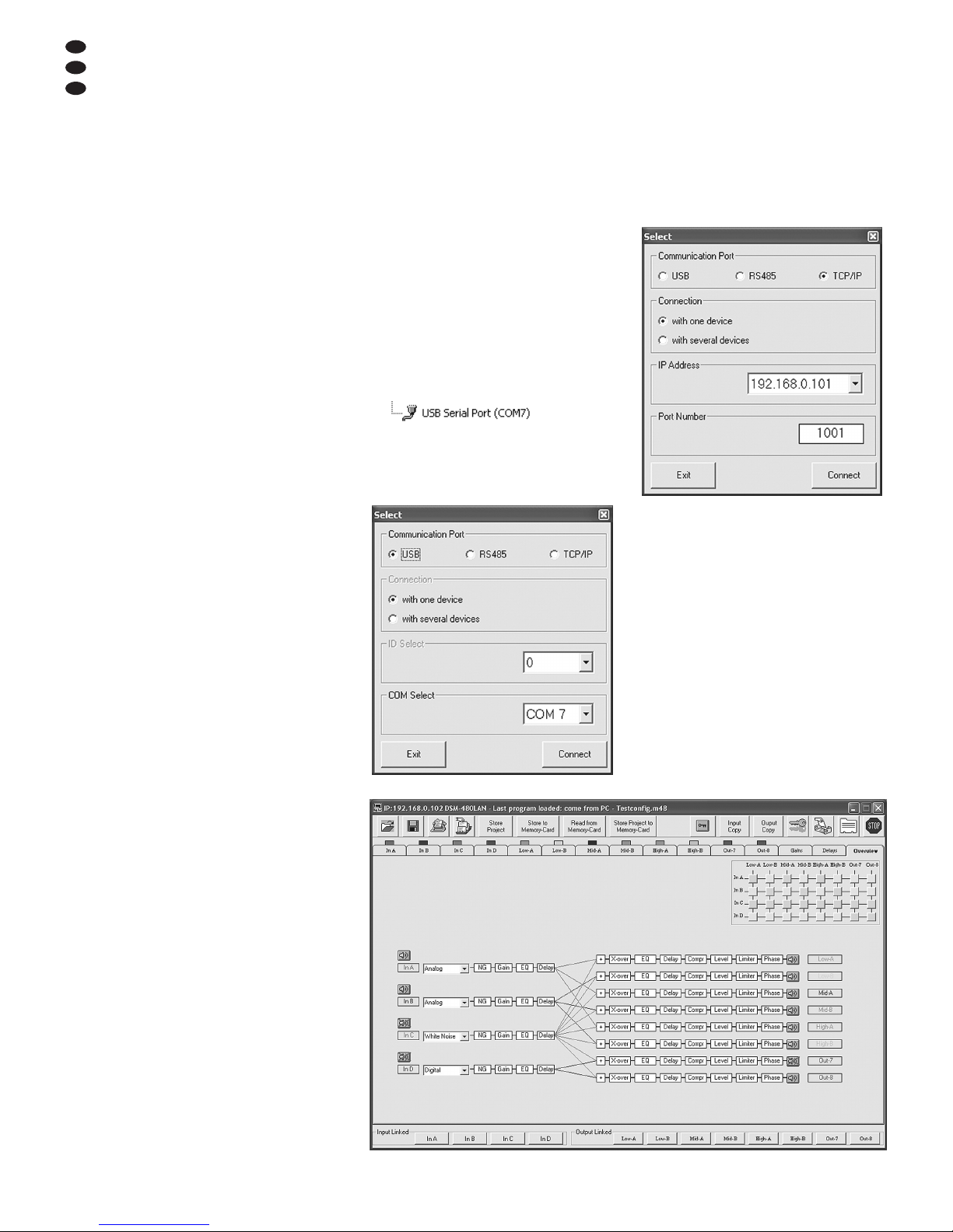
6 Fernbedienung über einen
Computer
Über die mitgelieferte Computer-Software kann
das DSM-480LAN fernbedient werden. Wie über
das Menü des Gerätes lassen sich alle Einstellungen vornehmen, jedoch ist die Darstellung
wesentlich übersichtlicher. Die Filtereinstellungen lassen sich auch grafisch per Maus durchführen und die resultierenden Frequenz- und
Phasenverläufe werden als Kurven angezeigt.
Darüber hinaus ist es möglich, die Parameter der
Noise-Gates zu ändern, Einstellungen zwischen
den Kanälen zu kopieren, Konfigurationen auf
dem Computer zu speichern und den kompletten
Konfigurationsspeicher als Projekt zu verwalten.
6.1 PC-Software installieren
Systemvoraussetzung für die Installation des
mitgelieferten Steuerprogramms ist ein PC mit
dem Betriebssystem Windows XP (SP2) oder
höher, einem Arbeitsspeicher von mindestens
256 MB, 50 MB freiem Festplattenspeicher und
einer USB-, Ethernet- oder RS-485-Schnittstelle.
Die Bildschirmauflösung sollte mindestens 1024
× 768 Bildpunkte betragen. Für die Installation
der PC-Software das Installationsprogramm
SETUP.EXE auf der mitgelieferten CD starten
und den Anweisungen des Installationsprogramms folgen.
Windows ist ein registriertes Warenzeichen der Microsoft Corporation in den
USA und anderen Ländern.
6.1.1 USB-Treiber installieren
Für die Anbindung über die USB-Schnittstelle
wird ein spezieller Treiber benötigt. Dieser ist auf
der beiliegenden CD enthalten. Zur automatischen Installation des Treibers die Datei
USB[…]SETUP.EXE aufrufen. Der Treiber
simuliert für die Bediensoftware eine serielle
Schnittstelle.
6.2 Schnittstelle wählen
Zum Umschalten zwischen der RS-485-Schnitt stelle, der Ethernet-Schnittstelle und dem USBAnschluss:
1) Durch Drücken des Knopfes UTILITY (5) das
Menü aufrufen.
Es wird
System Utilities
angezeigt.
2) Mit dem Drehknopf PM1/ ENTER (2) den
Menüpunkt
Interface Utilities
wählen und durch Drücken des Knopfes
bestätigen. Es wird
Interface Setup
angezeigt.
3) Den Knopf ENTER erneut drücken.
4) Mit dem Drehknopf PM2 (4) wählen, ob die
USB-Schnittstelle (
Source : USB
), die
RS-485-Schnittstelle (
Source : RS485
)
oder die Ethernet-Schnittstelle (
Source :
TCP/IP
) genutzt werden soll. Die aktuelle
Einstellung ist mit *markiert.
5) Die Auswahl durch Drücken des Knopfes
ENTER bestätigen oder den Vorgang durch
Drücken des Knopfes ESC (4) abbrechen.
6) Wurde die RS-485-Schnittstelle oder die
Ethernet-Schnittstelle gewählt, zur Unterscheidung mehrerer Geräte am Datenbus
zusätzlich die Gerätenummer festlegen:
Den Drehknopf PM1 nach rechts drehen,
sodass die Gerätenummer angezeigt wird,
z. B.:
Remote ID Num = 01 *
Bei der Steuerung über die Ethernet-Schnittstelle wird die Gerätenummer durch die letzten beiden Ziffern der IP-Adresse des Gerätes festgelegt, z. B.:
IP ADDR = 192.168.0.101*
Mit dem Drehknopf PM2 jeweils die ge wünschte Nummer einstellen (01bis 32)
und durch Drücken des Knopfes ENTER
bestätigen.
7) Zum Verlassen des Einstellmenüs dreimal
den Knopf ESC drücken.
6.3 PC-Software starten
1) Das Steuerprogramm DSM-480LAN Vx.x.EXE
auf dem PC starten.
2) Im Dialogfenster „Select“ unter „Communication Port“ die gewünschte Schnittstelle
(„USB“, „RS485“ oder „TCP/ IP“) wählen.
3) Wird „USB“ gewählt (
Abb. 8), muss unter
„COM Select“ die serielle Schnittstelle
gewählt werden, die der Treiber für die Software simuliert. Welche COM-Schnittstelle
dies aktuell ist, kann in den Einstellungen des
Betriebssystems unter Systemsteuerung
Systemeigenschaften (Hardware) GeräteManager Anschlüsse (COM und LPT) nachgesehen werden. Dort steht z. B.
Falls es zu Konflikten mit anderen Geräten
kommt, kann die Nummer der COM-Schnittstelle hier auch geändert werden (über
Eigenschaften Anschlusseinstellungen
Erweitert...).
4) Wird „RS485“ oder „TCP/ IP“ gewählt
(
Abb. 9), unter „Connection“ wählen, ob
nur ein DSM-480LAN oder mehrere Geräte
gesteuert werden sollen:
1 DSM-480LAN „with one device“
2 – 32 DSM-480LAN „with several devices“
Wurde „with one device“ gewählt, im Feld „ID
Select“ bzw. „IP Address“ die im jeweiligen
Gerät eingegebene Nummer (
Kap. 6.2)
wählen. Wurde „with several devices“ gewählt,
findet das Programm die Gerätenummern
beim folgenden Bedienschritt automatisch.
5) Die Auswahl durch Klicken auf die Schaltfläche „Connect“ bestätigen (oder das Programm durch Klicken auf „Exit“ wieder verlassen).
Das Hauptfenster öffnet sich und es wird
nach kurzer Zeit eine Liste mit den verbundenen Geräten angezeigt (
Abb. 10).
Das Gerät zeigt nun auf seinem Display:
PC Connection
System Lock
oder bei der Steuerung über Ethernet z. B.:
PC Connection
IP Addr [192.168.0.101]
und kann nicht mehr direkt bedient werden,
solange die Verbindung besteht (zum Trennen der Verbindung Kap. 6.11).
⑧
Fenster „Select Communication Port“ – USB
⑨
Fenster „Select Communication Port“ – TCP/ IP
D
A
CH
14
⑪
Ansicht „Overview“
Page 15

Konnte die Verbindung zu den Geräten
nicht hergestellt werden, wird eine Fehlermeldung angezeigt und das Starten des Steuerprogramms ohne Verbindung zu einem DSM480LAN (Demo-Modus) angeboten.
Durch Klicken auf „Ja“ startet das Programm im Demo-Modus mit einem oder mehreren virtuellen Geräten „Device Demo“ in der
Liste.
Durch Klicken auf „Nein“ wird das Programm beendet.
Folgende Ursachen können den Verbindungsaufbau verhindern:
– eine falsche Schnittstelle ist eingestellt
(
Kap. 6.2)
– die Geräte sind nicht richtig verbunden
– ein Gerät ist nicht eingeschaltet
– die Netzwerkeinstellungen am Computer
sind nicht korrekt (bei Verbindung über
Ethernet)
6) Durch Doppelklick auf ein Gerät in der Liste
„List ID“ (
Abb. 10) wird ein Fenster geöffnet, das die aktuelle Konfiguration dieses
Gerätes zeigt.
6.4 Ansichten
Im Fenster für jedes Gerät kann zwischen den
als „Registerkarten“ dargestellten Ansichten
umgeschaltet werden: „Overview“, „Delays“,
„Gains“ sowie die Einstellungen für jeden Eingangs- und Ausgangskanal.
6.4.1 Ansicht „Overview“
Diese Ansicht (
Abb. 11) bietet einen schnellen Überblick über die Konfiguration. Sie zeigt
links die vier Eingangskanäle und rechts die acht
Ausgangskanäle. Die Linien dazwischen stellen
die Zuordnung der Ausgänge zu den Eingängen
dar. Diese kann durch Klicken auf die entsprechenden Knotenpunkte in der Matrixdarstellung
oben rechts auch geändert werden. Zur Änderung des Mischverhältnisses der Signale ist es
dagegen erforderlich, in die Ansicht des jeweiligen Ausgangskanals zu wechseln (
Kap.
6.4.5.2).
Die Art der Signalquelle kann für jeden Eingangskanal per Listenfeld gewählt werden. Das
Symbol zeigt jeweils die Stummschaltung
eines Ein- oder Ausgangskanals.
6.4.1.1 Signalquelle wählen
Über die Listenfelder am Anfang der vier Eingangssignalketten kann jeweils zwischen dem
analogen Eingangssignal und dem digitalen Eingangssignal gewählt werden. Außerdem stehen
zu Testzwecken die beiden intern generierten
Signale „Weißes Rauschen“ und „Rosa Rauschen“ zur Auswahl. Diese Einstellung entspricht dem Menüpunkt
Source
im Menü zum
Konfigurieren eines Eingangs (
Kap. 5.3.2).
6.4.2 Ansicht „Delays“
Diese Ansicht (
Abb. 12) bietet eine Übersicht
für die Verzögerungseinstellungen aller Ein- und
Ausgänge. Zusätzlich wird auch hier die Zuordnung der Ausgänge zu den Eingängen als Linien
dargestellt. Diese kann durch Klicken auf die
entsprechenden Knotenpunkte in der Matrixdarstellung oben rechts auch geändert werden. Zur
Änderung des Mischverhältnisses der Signale
ist es dagegen erforderlich, in die Ansicht des
jeweiligen Ausgangskanals zu wechseln
(
Kap. 6.4.5.2).
Zur Änderung der Verzögerungswerte auf
die Pfeile neben den Eingabefeldern klicken:
Eine grobe Einstellung mit den Pfeilen über
„Adj“, eine Feineinstellung mit den Pfeilen über
„Fine“ durchführen. Alternativ kann der Wert
auch direkt in ein Feld eingegeben werden. Die
eingegebene Zahl wird dann auf den nächstmöglichen Wert gerundet.
Bei der Änderung der Werte ist zur Vereinfachung der Eingabe gleicher Werte eine Kopplung der Ein- oder Ausgänge möglich (Kap.
6.4.6).
6.4.2.1 Einheit für Signalverzögerung
Die Einheit für die Signalverzögerung kann unter
„Units“ als „Time“ (Zeit in ms) oder „Meter“ (Entfernung in m) gewählt werden (Näheres dazu
Kap. 5.2.1). Diese Einstellung ändert die Einheiten für alle Verzögerungszeiten dieses Gerätes.
6.4.3 Ansicht „Gains“
Diese Ansicht (
Abb. 13) bietet eine Übersicht
für die Verstärkungseinstellungen aller Ein- und
Ausgangskanäle. Zusätzlich werden die Stummschaltung aller Kanäle und die Phasenumkehr
sowie die LED-Anzeigenarten der Ausgänge
gezeigt.
Zur Änderung der Verstärkung eines Kanals
den entsprechenden Regler mit der Maus verschieben oder bei angewähltem Regler auf der
Tastatur mit den Pfeiltasten oder Bildlauftasten.
Zur Stummschaltung eines Kanals oder zur Aufhebung der Stummschaltung auf die Schaltfläche „Mute“ unterhalb des jeweiligen Reglers klicken. Bei stummgeschaltetem Kanal ist die
Schaltfläche rot.
Bei der Änderung der Werte ist zur Vereinfachung der Eingabe gleicher Werte eine Kopplung
der Ein- oder Ausgänge möglich (Kap. 6.4.6).
6.4.3.1 Phasenumkehr (Phase)
Ein Haken im Feld „Phase 180°“ unterhalb des
Reglers eines Ausgangskanals zeigt die Phasenumkehr des Ausgangssignals (vgl. „Polarity“
Kap. 5.4.10). Zum Umschalten auf das Feld
klicken.
⑩
Geräteliste „List ID“
D
A
CH
15
⑫
Ansicht „Delays“
⑬
Ansicht „Gains“
Page 16
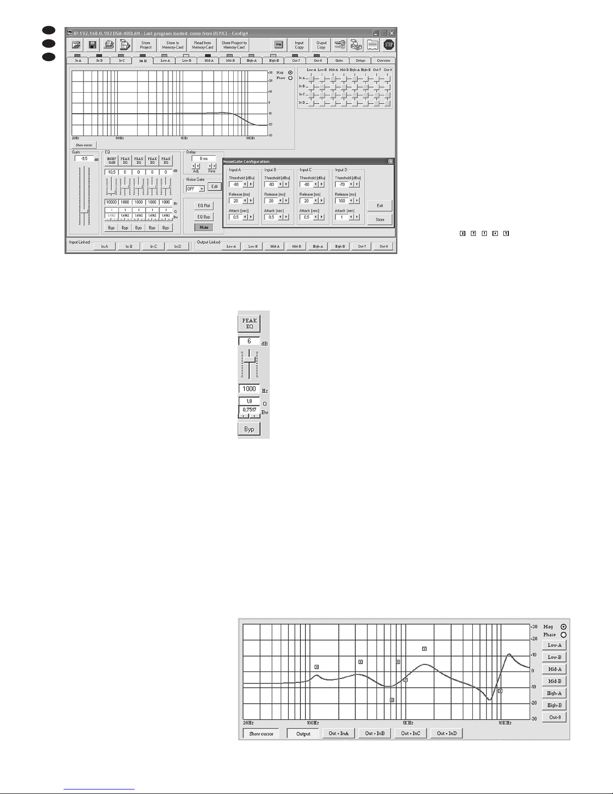
6.4.3.2 LED-Anzeige (Vu-Meter Mode)
Unter „Vu-Meter Mode“ kann für jeden Ausgang
die Anzeigeart der LED-Anzeige gewählt werden. Die Optionen entsprechen den folgenden
Einstellungen im Gerät (
Kap. 5.4.11).
„Level“ =
Level
„Limiter“ =
Limiter Act
„Compr“ =
RMS Cmp Act
6.4.4 Ansicht eines Eingangskanals
Diese Ansicht (
Abb. 14) bietet eine übersichtliche Darstellung für alle Parameter des
jeweiligen Eingangs. Bei der Änderung der
Werte ist zur Vereinfachung der Eingabe gleicher Werte für mehrere Eingänge auch eine
Kopplung der Eingänge möglich (Kap. 6.4.6).
6.4.4.1 Verstärkung
Unter „Gain“ kann die Eingangsverstärkung eingestellt werden. Zur Änderung der Verstärkung
den Regler mit der Maus verschieben oder bei
angewähltem Regler auf der Tastatur mit den
Pfeiltasten oder Bildlauftasten. Dies ist derselbe
Parameter wie in der Ansicht „Gains“ (Kap.
6.4.3).
6.4.4.2 Stummschaltung
Alternativ zur Stummschaltung in der Ansicht
„Delays“ (Kap. 6.4.3) kann der Eingang auch
in dieser Ansicht stummgeschaltet werden.
Zur Stummschaltung oder zur Aufhebung
der Stummschaltung auf die Schaltfläche „Mute“
klicken. Bei stummgeschaltetem Kanal ist die
Schaltfläche rot.
6.4.4.3 Signalverzögerung
Unter „Delay“ kann die Verzögerung für das Eingangssignal eingestellt werden. Die Einheit
(Meter oder Millisekunden) kann in der Ansicht
„Delays“ (
Kap. 6.4.2.1) geändert werden.
Zur Änderung des Verzögerungswertes auf
die Pfeile unter dem Eingabefeld klicken: Eine
grobe Einstellung mit den Pfeilen über „Adj“,
eine Feineinstellung mit den Pfeilen über „Fine“
durchführen. Alternativ kann der Wert auch
direkt in das Feld eingegeben werden. Die eingegebene Zahl wird dann auf den nächstmöglichen Wert gerundet. Dies ist derselbe Parameter wie in der Ansicht „Delays“ (Kap. 6.4.2).
6.4.4.4 Klangregelung
Unter „EQ“ können die 5 unabhängigen Filter
des Eingangskanals eingestellt werden (
Abb.
15).
1) Über die obere Schaltfläche (hier
„PEAK EQ“) den Filtertyp wählen
(Beschreibung der Filtertypen
Kap. 5.3.6.2)
2) Mit dem Schieberegler die Pegelanhebung oder -absenkung einstellen.
3) In das Feld unter dem Regler die
Filterfrequenz eingeben.
4) Die Filtergüte (Q) oder den relativen
Wert für die Bandbreite (Bw) in das
entsprechende Feld eingeben oder
durch Klicken auf die Pfeile unterhalb der Felder einstellen. Eine eingegebene Zahl wird auf den nächstmöglichen Wert gerundet.
Hinweis: Die Verfügbarkeit eines Parameters
hängt vom gewählten Filtertyp ab.
5) Durch Klicken auf die Schaltfläche „Byp“
kann das einzelne Filter deaktiviert werden.
Die Schaltfläche ist dann rot. Zum Wiedereinschalten des Filters erneut auf die Schaltfläche klicken.
6) Um alle Filter dieses Eingangs zu deaktivieren, auf die Schaltfläche „EQ Byp“ klicken.
Die Schaltfläche ist dann rot. Zum Wiedereinschalten der Filter erneut auf die Schaltfläche klicken.
7) Zum Zurücksetzen der Verstärkungswerte
aller Filter dieses Eingangs auf die Schaltfläche „EQ Flat“ klicken und in dem sich öffnen-
den Dialogfenster „EQ Flat – Are you sure?“
das Vorhaben bestätigen oder den Vorgang
abbrechen.
Anschließend sind alle Filter deaktiviert
und können durch Klicken auf die Schaltflächen „Byp“ wieder eingeschaltet werden.
Hinweis: Die Pegelanhebung/-absenkung und
die Filterfrequenz können alternativ auch auf
grafischem Wege eingestellt werden (
Kap.
6.4.4.5).
6.4.4.5 Frequenzgang
Im oberen Bereich der Ansicht wird der Frequenzgang des Eingangskanals, abhängig von
der Einstellung der Eingangsverstärkung und
der Klangregelung, dargestellt.
Oben rechts im Diagramm kann zwischen
der Darstellung als Amplituden-Frequenzgang
„Mag“ oder Phasen-Frequenzgang „Phase“
gewählt werden.
Durch Klicken auf die Schaltfläche „Show
cursor“ wird zu jedem Filter ein grafischer
Bezugspunkt (
, , , , ) neben der Kurve
gezeigt (
ähnlich Abb. 16). Mithilfe der Maus
lassen sich die Filter jetzt auch durch Verschieben dieser Punkte in Bezug auf Frequenz und
Pegelanhebung/ -ab senkung grafisch einstellen
(wenn der gewählte Filtertyp dies zulässt).
Durch erneutes Klicken auf die Schaltfläche
„Show cursor“ werden die Bezugspunkte wieder
ausgeblendet.
6.4.4.6 Noise-Gate
Zur Unterdrückung leiser Störgeräusche in Signalpausen ist in jedem Eingangskanal ein NoiseGate verfügbar.
Im Listenfeld unter „Noise Gate“ wählen, ob die
Störunterdrückung ein- (ON) oder ausgeschaltet
(OFF) sein soll. Zur Änderung der Betriebsparameter für das Noise-Gate:
1) Neben dem Listenfeld auf die Schaltfläche
„Edit“ klicken. Das Fenster „Noise Gate Configuration“ (
Abb. 14) öffnet sich und zeigt
die Noise-Gate-Parameter für alle Eingänge.
2) Durch Klicken auf die Pfeile neben den Ein-
gabefeldern die gewünschten Werte einstellen.
„Threshold“: Schwellwert, unterhalb dessen
ein Signal unterdrückt wird
„Release“: Rückstellzeit, in der ein Signal
nach dem Unterschreiten des
Schwell wertes noch hörbar
bleibt
„Attack“: Ansprechzeit, bestimmt die Ver-
zögerung zwischen der Überschreitung des Schwellwertes
und dem Durchlassen des Signals
3) Zum Speichern der durchgeführten Änderun-
gen auf die Schaltfläche „Store“ klicken und in
dem sich öffnenden Dialogfenster „Upgrade
Noise Gate Configuration – Are you sure?“
⑮
„EQ“
D
A
CH
16
⑯
Filterkurve mit Marken
⑭
Ansicht Eingangskanal „In D“ mit Fenster „Noise Gate Configuration“
Page 17
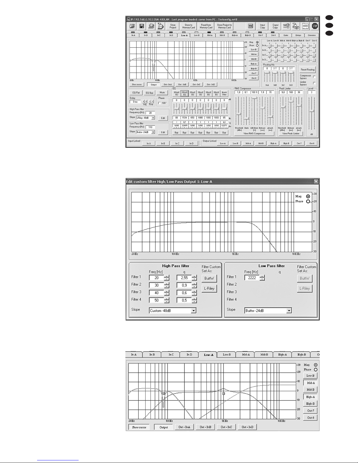
das Vorhaben bestätigen oder den Vorgang
abbrechen.
4) Durch Klicken auf die Schaltfläche „Exit“ das
Fenster „Noise Gate Configuration“ wieder
ausblenden.
6.4.5 Ansicht eines Ausgangskanals
Diese Ansicht (
Abb. 17) bietet eine übersichtliche Darstellung für alle Parameter des
jeweiligen Ausgangs. Bei der Änderung der
Werte ist zur Vereinfachung der Eingabe gleicher
Werte für mehrere Ausgänge auch eine Kopplung der Ausgänge möglich (
Kap. 6.4.6).
6.4.5.1 Stummschaltung
Alternativ zur Stummschaltung in der Ansicht
„Gains“ (
Kap. 6.4.3) kann der Ausgang auch
in dieser Ansicht stummgeschaltet werden.
Zur Stummschaltung oder zur Aufhebung
der Stummschaltung auf die Schaltfläche „Mute“
klicken. Bei stummgeschaltetem Kanal ist die
Schaltfläche rot.
6.4.5.2 Eingangssignale wählen
Über die Zuordnungsmatrix (oben rechts) die
Eingangssignale wählen, die der Ausgangskanal bekommen soll. Jede Zeile der Matrix repräsentiert einen Eingangskanal, jede Spalte einen
Ausgangskanal. Durch Klicken auf einen Knotenpunkt kann ein Eingang einem Ausgang
zugewiesen (das Quadrat am Knotenpunkt wird
grün) oder die Zuweisung wieder aufgehoben
werden. Unter „Routing Mix“ kann für jedes
zugewiesene Eingangssignal der Pegel mit dem
Schieberegler um bis zu 30 dB gedämpft werden
(die Dämpfung gilt nur für diesen Ausgangskanal). Dadurch lassen sich unterschiedliche Signalmischungen für die Ausgänge erzielen. Über
die Schaltfläche „Reset Routing“ werden, nach
Bestätigen einer Sicherheitsabfrage, alle Zuweisungen zurückgesetzt.
Die Kanalzuordnung wird in den Ansichten
„Overview“ (
Abb. 11) und „Delays“ (Abb.
12) durch farbige Linien dargestellt und kann
dort ebenfalls geändert werden.
6.4.5.3 Signalverzögerung
Unter „Delay“ kann die Verzögerung für das Ausgangssignal eingestellt werden. Die Einheit
(Meter oder Millisekunden) kann in der Ansicht
„Delays“ (
Kap. 6.4.2.1) geändert werden.
Zur Änderung des Verzögerungswertes auf
die Pfeile neben dem Eingabefeld klicken: Eine
grobe Einstellung mit den Pfeilen über „Adj“,
eine Feineinstellung mit den Pfeilen über „Fine“
durchführen. Alternativ kann der Wert auch
direkt in das Feld eingegeben werden. Die eingegebene Zahl wird dann auf den nächstmöglichen Wert gerundet.
Dies ist derselbe Parameter wie in der
Ansicht „Delays“ (
Kap. 6.4.2).
6.4.5.4 Hochpass- und Tiefpassfilter
Die Hochpass- und Tiefpassfilter der Ausgänge
sollen in Kombination primär die Funktion einer
Frequenzweiche zur frequenzabhängigen Aufteilung eines Eingangssignals auf zwei oder
mehrere Ausgangskanäle erfüllen. Bei der Einstellung der Filter hilft auch die Möglichkeit, den
Frequenzgang mehrerer Ausgänge in einem
Diagramm darstellen zu können (
Kap.
6.4.5.6).
1) Zur Einstellung des Hochpassfilters unter
„High Pass filter“ in das Feld „Frequency
[Hz]“ die Grenzfrequenz eingeben und aus
der Liste „Slope“ die Filtercharakteristik wählen oder „Bypass“, wenn das Filter nicht
genutzt werden soll (Näheres zur Filtercharakteristik
Kap. 5.4.5).
D
A
CH
17
⑰
Ansicht Ausgangskanal „Low-A“
⑱
Fenster „Edit custom filter ...“
⑲
Filterkurven mehrerer Ausgänge
Page 18
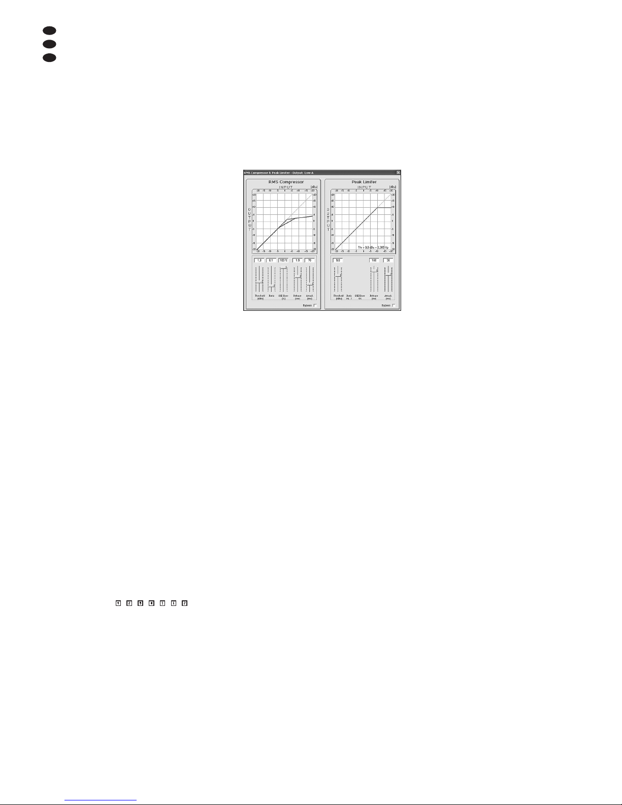
2) Zur Einstellung des Tiefpassfilters unter „Low
Pass filter“ in das Feld „Frequency [Hz]“ die
Grenzfrequenz eingeben und aus der Liste
„Slope“ die Filtercharakteristik wählen oder
„Bypass“, wenn das Filter nicht genutzt werden soll (Näheres zur Filtercharakteristik
Kap. 5.4.5).
3) Für die Filtercharakteristiken „Custom...“ zur
Einstellung der zusätzlichen Parameter auf
eine der beiden Schaltflächen „Edit“ klicken.
Das Fenster „Edit custom filter High / Low
Pass...“ (Abb. 18) öffnet sich daraufhin.
Im Gegensatz zur Darstellung des Frequenzgangs im Hauptfenster des Ausgangskanals (
Kap. 6.4.5.6) wird hier nur die Frequenzgangänderung durch das Hoch- und
Tiefpassfilter dargestellt.
Oben rechts im Diagramm kann zwischen
der Darstellung als Amplituden-Frequenzgang „Mag“ oder Phasen-Frequenzgang
„Phase“ gewählt werden.
Abhängig von der gewählten Filtercharakteristik „Custom...“ werden zusätzliche Eingabefelder für weitere Parameter eingeblendet. Über die Schaltflächen „ButtW“ und
„L-Riley“ lassen sich, wenn möglich, die Filtercharakteristiken Butterworth und LinkwitzRiley als Grundlage für eine eigene Einstellung vorgeben.
6.4.5.5 Klangregelung
Unter „EQ“ können die 7 unabhängigen Filter
des Ausgangskanals, wie schon für die Eingangskanäle beschrieben, eingestellt werden
(
Kap. 6.4.4.4).
6.4.5.6 Frequenzgang
Im oberen Bereich der Ansicht wird der Frequenzgang des Ausgangskanals, abhängig von
der Einstellung der Hoch- und Tiefpassfilter, der
Klangregelung und der Ausgangsverstärkung
dargestellt.
Oben rechts im Diagramm kann zwischen
der Darstellung als Amplituden-Frequenzgang
„Mag“ oder Phasen-Frequenzgang „Phase“ ge wählt werden.
Unterhalb des Diagramms kann über die
Schaltflächen gewählt werden, ob nur die Einstellungen des Ausgangskanals „Output“ ge zeigt werden soll oder zusätzlich die Einstellungen eines Eingangskanals, z. B. „Out + In A“ bei
der Darstellung berücksichtigt werden sollen.
Die Kurven der anderen Ausgangskanäle
können zusätzlich über die entsprechend be nannten Schaltflächen rechts neben dem Diagramm ein- und ausgeblendet werden (
Abb.
19). Dadurch lässt sich z. B. darstellen, wie sich
die Amplituden-Frequenzgänge der Kanäle
einer Frequenzweiche ergänzen.
Durch Klicken auf die Schaltfläche „Show
cursor“ wird bei der Darstellung als AmplitudenFrequenzgang zu jedem Filter ein grafischer
Bezugspunkt (
, , , , , , ) neben der
Kurve gezeigt (Abb. 16). Mithilfe der Maus
lassen sich die Filter jetzt auch durch Verschieben dieser Punkte in Bezug auf Frequenz und
Pegelanhebung/ -ab senkung grafisch einstellen
(wenn der gewählte Filtertyp dies zulässt).
Durch erneutes Klicken auf die Schaltfläche
„Show cursor“ werden die Bezugspunkte wieder
ausgeblendet.
6.4.5.7 Kompressor
Zur Änderung der Kompressor-Parameter unter
„RMS Compressor“ den entsprechenden Regler
mit der Maus verschieben oder bei angewähltem
Regler auf der Tastatur mit den Pfeiltasten oder
Bildlauftasten. (Näheres zur Funktion und zu
den Parametern des Kompressors
Kap.
5.4.7)
Zum Umgehen des Kompressors oder zum
Wiedereinschalten auf das Kästchen „Compressor bypass“ klicken. Bei gesetztem Haken ist der
Kompressor ausgeschaltet.
Durch Klicken auf die Schaltfläche „View
RMS Compressor“ öffnet sich das Fenster „RMS
Compressor & Peak Limiter ...“ (
Abb. 20). Es
enthält die gleichen Regler für die Parameter
und das Kästchen „Bypass“ zur Umgehung des
Kompressors. Zusätzlich wird der Signalpegel
des Kompressor-Eingangs und des Ausgangs in
Abhängigkeit von den Kompressoreinstellungen
grafisch dargestellt. Die Auswirkung einer Änderung der Parameter „Threshold“, „Ratio“ oder
„Soft/ Hard Knee“ wird hier sofort sichtbar.
6.4.5.8 Verstärkung
Der Pegel des Ausgangssignals kann unter
„Level“ durch die Einstellung der Verstärkung im
Bereich -18 dB bis +18 dB angepasst werden.
Hierüber lässt sich auch eine durch den Kompressor verursachte Pegelreduzierung wieder
ausgleichen.
Zur Änderung der Verstärkung den Regler
mit der Maus verschieben oder bei angewähltem
Regler auf der Tastatur mit den Pfeiltasten oder
Bildlauftasten.
Dies ist derselbe Parameter wie in der
Ansicht „Gains“ (
Kap. 6.4.3).
6.4.5.9 Pegelbegrenzung (Limiter)
Zur Änderung der Limiter-Parameter unter
„Peak Limiter“ den entsprechenden Regler mit
der Maus verschieben oder bei angewähltem
Regler auf der Tastatur mit den Pfeiltasten oder
Bildlauftasten. (Näheres zur Funktion und zu
den Parametern des Limiters
Kap. 5.4.9)
Zum Umgehen des Limiters oder zum Wiedereinschalten auf das Kästchen „Limiter by pass“ klicken. Bei gesetztem Haken ist der Limiter ausgeschaltet.
Durch Klicken auf die Schaltfläche „View
Peak Limiter“ öffnet sich das Fenster „RMS
Compressor & Peak Limiter ...“ (
Abb. 20). Es
enthält die gleichen Regler für die Parameter
und das Kästchen „Bypass“ zur Umgehung des
Limiters. Zusätzlich wird der Signalpegel des
Limiter-Eingangs und des Ausgangs in Abhängigkeit von den Limitereinstellungen grafisch
dargestellt. Die Auswirkung einer Änderung des
Parameters „Threshold“ wird sofort sichtbar.
Unterhalb der Kurve wird zusätzlich zum über
„Threshold“ eingestellten Maximalpegel [dBu]
die entsprechende Spitzenspannung [Vp] angezeigt.
6.4.5.10 Phasenumkehr
Ein Haken im Feld „Phase 180°“ zeigt die Phasenumkehr des Ausgangssignals (vgl. „Polarity“
Kap. 5.4.10). Zum Umschalten auf das Feld
klicken. Dies ist derselbe Parameter wie in der
Ansicht „Gains“ (
Kap. 6.4.3.1).
6.4.6 Kopplung der Kanäle
Sollen bestimmte Parameter für mehrere Ausgänge oder Eingänge gleich eingestellt werden,
ist es möglich, die Ein- oder Ausgänge während
der Einstellung zu koppeln. Die an einem Ausgang geänderten Parameter werden nun bei
allen gekoppelten Ausgängen identisch eingestellt. Ebenso werden die während der Kopplung
der Eingänge durchgeführten Einstellungen
gleichzeitig an den gewählten Eingangskanälen
vorgenommen. Dabei werden jeweils nur die
während der Kopplung geänderten Parameter
angeglichen. Alle individuellen Einstellungen der
Ein- bzw. Ausgänge bleiben erhalten.
Zum Koppeln der Eingänge:
1) Am unteren Rand des Fensters unter „Input
Linked“ auf die Schaltflächen aller Eingänge
klicken, deren Parameter gleich eingestellt
werden sollen. Wird gerade die Ansicht für
einen bestimmten Eingang (
Abb. 14)
gezeigt, auch die Schaltfläche für diesen Eingang mit anklicken. Die Schaltflächen er scheinen „hineingedrückt“ und die Be schriftung wird blau.
Die Kopplung bleibt auch beim Umschal-
ten auf eine andere Ansicht erhalten.
2) Um die Kopplung für einen Eingang zu lösen,
erneut auf dessen Schaltfläche klicken.
Zum Koppeln der Ausgänge:
1) Am unteren Rand des Fensters unter „Output
Linked“ auf die Schaltflächen aller Ausgänge
klicken, deren Parameter gleich eingestellt
werden sollen. Wird gerade die Ansicht für
einen bestimmten Ausgang (
Abb. 17)
gezeigt, auch die Schaltfläche für diesen
Ausgang mit anklicken. Die Schaltflächen
erscheinen „hineingedrückt“ und die Be schriftung wird blau.
Die Kopplung bleibt auch beim Umschal-
ten auf eine andere Ansicht erhalten.
2) Um die Kopplung für einen Ausgang zu
lösen, erneut auf dessen Schaltfläche klicken.
Ausgenommen von der Kopplung sind die Funktionen „Mute“, „Vu-Meter Mode“, die Kanalzuordnung „Routing Mix“ und die Benennung der
Ausgänge.
6.5 Einstellungen kopieren
Im Gegensatz zur Kopplung der Kanäle, bei der
nur die während der Kopplung geänderten Parameter angeglichen werden, überträgt die Kopierfunktion alle Einstellungen eines Kanals auf
einen anderen. Nicht kopiert werden dabei die
Einstellungen für „Mute“, „Vu-Meter Mode“, die
Kanalzuordnung „Routing Mix“ und die Benennung der Ausgänge.
6.5.1 Einstellungen eines Eingangs
kopieren
1) Auf die Schaltfläche „Input Copy“ klicken.
Das Dialogfenster „Input copy channel“ öffnet
sich.
2) Unter „Input Source“ den Eingang wählen,
dessen Einstellungen auf einen anderen
übertragen werden sollen.
3) Unter „Input Destination“ den Eingang wählen, der die Einstellungen übernehmen soll.
4) Die Auswahl mit „Confirm“ bestätigen oder
den Vorgang mit „Cancel“ abbrechen.
5) In einem weiteren Dialogfenster „Copy Input –
Are you sure?“ das Vorhaben bestätigen oder
den Vorgang abbrechen.
⑳
Fenster „RMS Compressor & Peak Limiter“
D
A
CH
18
Page 19
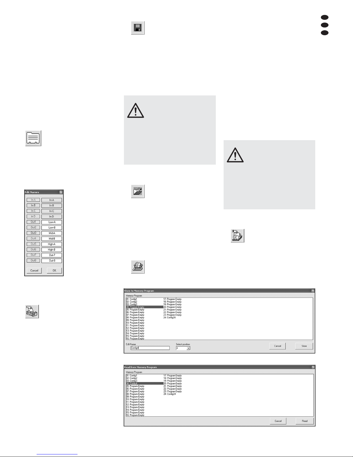
6.5.2 Einstellungen eines Ausgangs
kopieren
1) Auf die Schaltfläche „Output Copy“ klicken.
Das Dialogfenster „Output copy channel“ öffnet sich.
2) Unter „Output Source“ den Ausgang wählen,
dessen Einstellungen auf einen anderen
übertragen werden sollen.
3) Unter „Output Destination“ den Ausgang
wählen, der die Einstellungen übernehmen
soll.
4) Die Auswahl mit „Confirm“ bestätigen oder
den Vorgang mit „Cancel“ abbrechen.
5) In einem weiteren Dialogfenster „Copy Out-
put – Are you sure?“ das Vorhaben bestätigen
oder den Vorgang abbrechen.
6.6 Ausgänge umbenennen
Zum Umbenennen der Ausgänge auf die Schaltfläche
klicken oder auf den Namen eines Einoder Ausgangs in der Ansicht „Overview“ (Abb. 11). Das Fenster „Edit
Names“ (
Abb. 21) wird eingeblendet. Die Namen der Ausgänge Out1 bis Out8
können hier geändert werden. Ein Name darf
aus max. 6 Zeichen bestehen. Dabei sollte auf
die Verwendung von (landesspezifischen) Sonderzeichen (z. B. ä, ö, ü, ß, è, ô, ì, á, ñ, μ) verzichtet werden, da diese auf dem Display des
DSM-480LAN nicht korrekt dargestellt werden.
6.7 Gerät umbenennen
Zum Umbenennen des Gerätes auf die folgende
Schaltfläche klicken.
Das Fenster „Name Device – Edit Name
Device“ wird eingeblendet und der aktu-
elle Name des Gerätes kann geändert
werden. Der Name kann aus max. 16 Zeichen
bestehen. Er erscheint in der Liste „List ID“
(Abb. 10) und dient bei der Verwendung
mehrerer Geräte zu deren Unterscheidung.
6.8 Verwaltung der Konfigurationen
Jede im DSM-480LAN eingestellte Konfiguration
kann auf einem seiner 24 Speicherplätze als
„Program“ dauerhaft gespeichert werden. Mithilfe des Steuerprogramms können diese Konfigurationen aus dem Speicher des DSM-480LAN
gelesen und auf dem Computer gespeichert
werden oder sie können z. B. modifiziert und in
das Gerät zurückübertragen werden.
6.8.1 Konfiguration auf dem Computer
speichern
Zum Speichern der aktuellen Konfiguration auf
dem Computer:
1) Auf die folgende Schaltfläche klicken.
Es öffnet sich das Dialogfenster
„Speichern unter“.
2) Den gewünschten Dateinamen eingeben,
den Speicherort wählen und die Datei speichern.
Als Vorgabe ist für den Speicherort der bei
der Programminstallation automatisch angelegte Unterordner „Program“ ausgewählt. Die
Dateiendung *.m48 wird dem eingegebenen
Namen automatisch angehängt.
6.8.2 Konfiguration vom Computer laden
Zum Laden einer auf dem Computer gespeicherten Konfiguration:
1) Auf die folgende Schaltfläche klicken.
Es öffnet sich das
Dialogfenster „Öffnen“.
2) Die gewünschte Datei auswählen und das
Öffnen bestätigen.
Wenn die ausgewählte Datei keine gültige
Konfiguration enthält, erscheint die Meldung
„Load Program – File not admitted“.
6.8.3 Konfiguration im Gerät speichern
Zum Speichern der aktuellen Konfiguration im
DSM-480LAN:
1) Auf die folgende Schaltfläche klicken.
Es öffnet sich das Dialogfenster
„Store to Memory Program“
(
Abb. 22).
2) Im Feld „Select Position“ oder durch Doppel-
klick auf einen Eintrag in der Liste unter
„Memory Program“ den Speicherplatz wählen. Es kann ein freier Speicherplatz „Program Empty“ gewählt werden oder ein bereits
belegter, um dessen Inhalt zu überschreiben.
3) Im Feld „Edit Name“ den Namen für die Konfiguration eingeben. Der Name kann aus max.
16 Zeichen bestehen. Dabei sollte auf die Verwendung von (landesspezifischen) Sonderzeichen (z. B. ä, ö, ü, ß, è, ô, ì, á, ñ, μ) verzichtet werden, da diese auf dem Display des
DSM-480LAN nicht korrekt dargestellt werden.
4) Zum Speichern auf die Schaltfläche „Store“
klicken oder den Vorgang mit „Cancel“ abbrechen.
5) In einem weiteren Dialogfenster „Store Program – Are you sure?“ das Vorhaben bestätigen oder den Vorgang abbrechen.
Nach Abschluss des Speichervorgangs
schließt sich das Fenster „Store to Memory
Program“.
6.8.4 Konfiguration aus dem Gerät laden
Zum Laden einer Konfiguration aus dem Speicher des DSM-480LAN:
1) Auf die folgende Schaltfläche klicken.
Es öffnet sich das Dialogfenster
„Read from Memory Program“
(
Abb. 23).
2) Aus der Liste unter „Memory Program“ eine
Konfiguration wählen.
3) Zum Laden auf die Schaltfläche „Read“ kli-
cken oder den Vorgang mit „Cancel“ abbrechen.
Wurde ein freier Speicherplatz „Program
Empty“ gewählt, erscheint eine Fehlermeldung.
VORSICHT Überprüfen Sie unbedingt vor dem
Laden einer Konfiguration, ob
diese mit der angeschlossenen
Lautsprecherkonstellation über-
einstimmt.
Durch die flexiblen Konfigurationsmöglichkeiten des DSM-480LAN kann z. B. ein Ausgang,
der für die Ansteuerung eines Hochtonlautsprechers konfiguriert ist, nach dem Laden einer
anderen Konfiguration zum Tieftonausgang
werden. Für einen Hochtonlautsprecher an diesem Ausgang besteht dann die Gefahr der
Überlastung.
㉑
Fenster „Edit Names“
VORSICHT Überprüfen Sie unbedingt vor dem
Laden einer Konfiguration, ob
diese mit der angeschlossenen
Lautsprecherkonstellation über-
einstimmt.
Durch die flexiblen Konfigurationsmöglichkeiten des DSM-480LAN kann z. B. ein Ausgang,
der für die Ansteuerung eines Hochtonlautsprechers konfiguriert ist, nach dem Laden einer
anderen Konfiguration zum Tieftonausgang
werden. Für einen Hochtonlautsprecher an diesem Ausgang besteht dann die Gefahr der
Überlastung.
D
A
CH
19
㉒
Fenster „Store to Memory Program“
㉓
Fenster „Read from Memory Program“
Page 20
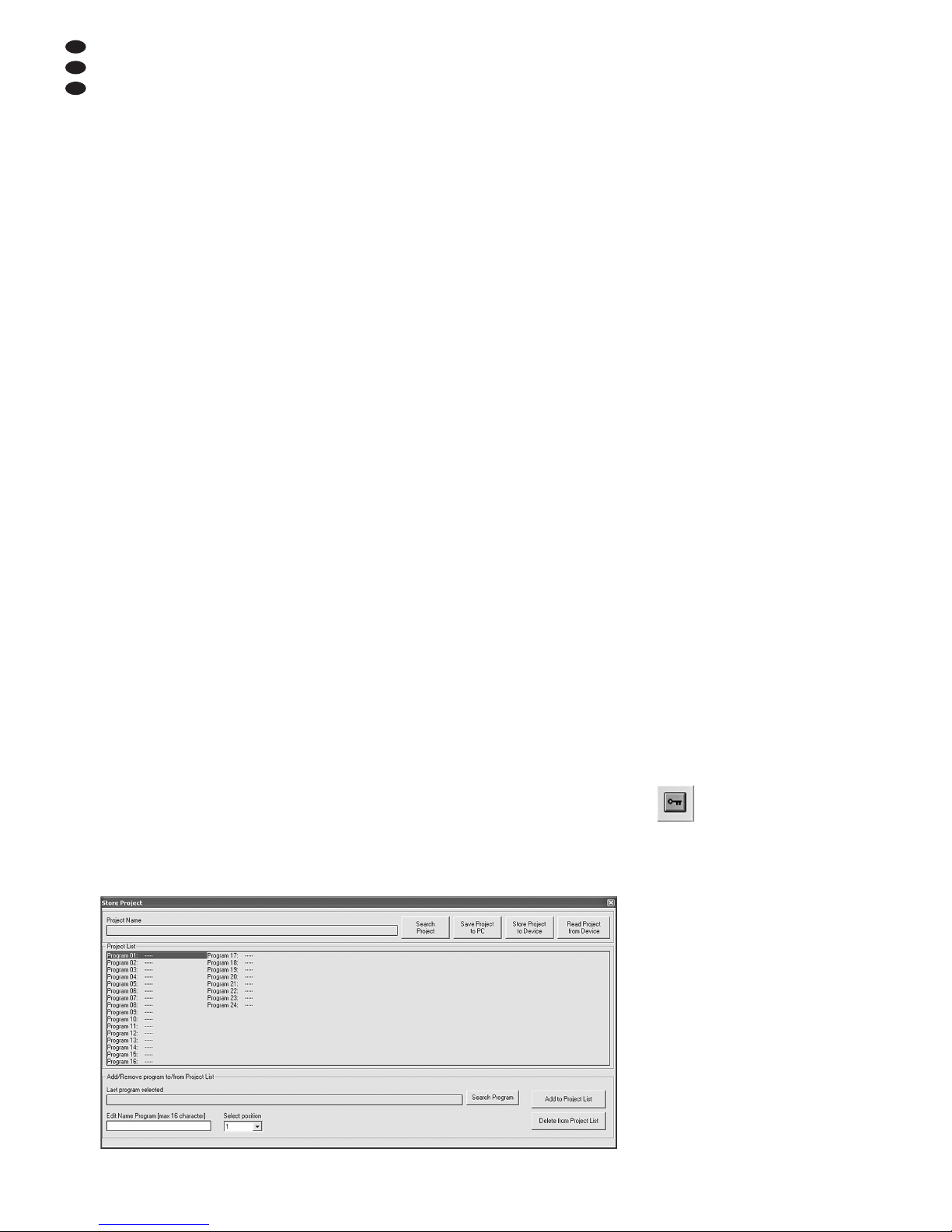
4) In einem weiteren Dialogfenster „Read
Memory Program – Overwriting current editing, are you sure?“ das Vorhaben bestätigen
oder den Vorgang abbrechen.
Nach dem Ladevorgang schließt sich das
Fenster „Read from Memory Program“.
6.8.5 Konfigurationen auf der Speicherkarte
Wie im Kapitel 6.8.3 für die Speicherung einer
Konfiguration im Gerät beschrieben ist, kann
über die Schaltfläche „Store to Memory-Card“
eine Konfiguration auf eine im Gerät befindliche
Speicherchipkarte geschrieben werden.
Ebenso lässt sich entsprechend Kapitel
6.8.4 über die Schaltfläche „Read from Memory-
Card“ eine Konfiguration von einer im Gerät
befindlichen Speicherchipkarte auf den Computer laden.
Befindet sich keine Karte im Gerät, wird die folgende Fehlermeldung angezeigt: „Memory Card
not present“
6.8.6 Konfigurationen als Projekt verwalten
Damit die Konfigurationen nicht immer einzeln
übertragen, gespeichert und geladen werden
müssen, lassen sich bis zu 24 Konfigurationen
(also alle Speicherplätze des DSM-480LAN) zu
Projekten zusammenfassen. Ein Projekt kann
aus einzelnen Konfigurationen neu zusammengestellt werden, wenn diese bereits auf dem
Computer gespeichert wurden (
Kap. 6.8.1).
Alternativ können auch alle Konfigurationen aus
dem Speicher des DSM-480LAN oder von der
Speicherkarte als ein Projekt geladen werden,
um dann als Sicherungskopie auf dem Computer gespeichert zu werden oder als Grundlage
für ein neues Projekt zu dienen.
6.8.6.1 Projekt zusammenstellen
Zum Zusammenstellen eines neuen Projektes:
1) Auf die Schaltfläche „Store Project“ klicken.
Es öffnet sich das Fenster „Store Project“
(
Abb. 24).
2) Im Feld „Select Position“ oder in der Liste
unter „Project List“ den Speicherplatz wählen.
3) Über die Schaltfläche „Search Program“ eine
auf dem Computer gespeicherte Konfiguration laden.
4) Im Feld „Edit Name Program“ den Namen für
die Konfiguration eingeben. Der Name kann
aus max. 16 Zeichen bestehen. Dabei sollte
auf die Verwendung von (landesspezifischen)
Sonderzeichen (z. B. ä, ö, ü, ß, è, ô, ì, á, ñ, μ)
verzichtet werden, da diese auf dem Display
des DSM-480LAN nicht korrekt dargestellt
werden.
5) Über die Schaltfläche „Add to Project List“ die
Konfiguration der Liste hinzufügen.
6) Die Schritte 2) bis 5) wiederholen, bis alle
gewünschten Konfigurationen im Projekt enthalten sind.
7) Um eine Konfiguration aus der Projektliste zu
entfernen, im Feld „Select Position“ oder in
der Liste unter „Project List“ ihren Speicherplatz wählen und auf die Schaltfläche „Delete
from Project List“ klicken. In dem sich öffnenden Dialogfenster „Delete Program from the
Project list, are you sure?“ das Vorhaben
bestätigen oder den Vorgang abbrechen.
8) Vor dem Schließen des Fensters „Store Project“ unbedingt das Projekt speichern
(
Kap. 6.8.6.2), weil es sonst verloren ist.
6.8.6.2 Projekt speichern
Nachdem ein Projekt neu erstellt oder aus dem
Speicher des DSM-480LAN geladen wurde,
zum Speichern des Projektes:
1) Im Fenster „Store Project“ (
Abb. 24) auf
die Schaltfläche „Save Project to PC“ klicken.
2) Den gewünschten Dateinamen eingeben,
den Speicherort wählen und die Datei speichern.
Als Vorgabe ist für den Speicherort der bei
der Programminstallation automatisch angelegte Unterordner „Project“ ausgewählt. Die
Dateiendung *.prj wird dem eingegebenen
Namen automatisch angehängt.
6.8.6.3 Projekt laden
Zum Laden eines auf dem Computer gespeicherten Projektes:
1) Auf die Schaltfläche „Store Project“ klicken.
Es öffnet sich das Fenster „Store Project“
(
Abb. 24).
2) Auf die Schaltfläche „Search Project“ klicken.
Es öffnet sich das Dialogfenster „Öffnen“.
3) Die gewünschte Projekt-Datei auswählen und
das Öffnen bestätigen.
Im Fenster „Store Project“ steht jetzt unter
„Project Name“ der Dateiname und Speicherort des geladenen Projekts.
6.8.6.4 Projekt ins Gerät übertragen
Ein Projekt kann komplett in den Speicher des
DSM-480LAN übertragen werden. Dabei werden die bisherigen Speicherinhalte überschrieben. Bei leeren Positionen der Projektliste „-----“
bleibt der Inhalt des entsprechenden Speicherplatzes im Gerät aber unverändert. So ist es
möglich, nur einige Konfigurationen im Gerät zu
ergänzen oder auszutauschen.
Zum Übertragen des aktuellen Projektes in den
Speicher des DSM-480LAN:
1) Im Fenster „Store Project“ (
Abb. 24) auf die
Schaltfläche „Store Project to Device“ klicken.
2) In dem sich öffnenden Dialogfenster „Store
current project to device, are you sure?“ das
Vorhaben bestätigen oder den Vorgang
abbrechen.
Nach erfolgreicher Übertragung erscheint
die Meldung „Project stored on the device“.
6.8.6.5 Projekt aus dem Gerät laden
Um den gesamten Konfigurationsspeicher des
DSM-480LAN als Projekt in den Computer zu
laden:
1) Im Fenster „Store Project“ (
Abb. 24) auf
die Schaltfläche „Read Project from Device“
klicken.
2) In dem sich öffnenden Dialogfenster „Read
current project from device, are you sure?“
das Vorhaben bestätigen oder den Vorgang
abbrechen.
Der Fortschritt der Übertragung wird unten
im Fenster „Store Project“ angezeigt.
Nach dem Laden steht unter „Project Name“ als
Quelle des geladenen Projekts „Device project“.
Das Projekt kann jetzt z. B. auf dem Computer
gesichert werden (
Kap. 6.8.6.2) oder, wie
unter „Projekt zusammenstellen“ beschrieben
(Kap. 6.8.6.1), mit gespeicherten Konfigurationen ergänzt und dann zurück in das Gerät
übertragen werden (Kap. 6.8.6.4).
6.8.6.6 Projektverwaltung mit Speicherkarte
In den vorangehenden Kapiteln ist die Speicherung und das Laden eines Projekts zwischen
dem Speicher des Geräts und dem PC beschrieben. Über die Schaltfläche „Store Project to
Memory-Card“ kann in gleicher Weise die Verwaltung von Projekten zwischen dem PC und
der Speicherkarte vorgenommen werden.
Für die Speicherung der Konfigurationen
von einer Speicherkarte als Projekt wird auf dem
PC ein eigener Ordner „CardProject“ angelegt.
Es können aber auch andere Speicherorte
gewählt werden.
6.9 Gerät sperren
Wie in Kapitel 5.6.2 beschrieben, kann das
Gerät gegen versehentliches Verstellen gesperrt
werden. Dies ist auch über das Steuerprogramm
möglich:
1) Auf die folgende Schaltfläche klicken.
Die Schaltfläche erscheint jetzt rot
umrandet und die Bedienung ist
gesperrt.
Auch nach dem Trennen der Verbindung
(
Kap. 6.11) bleibt das Gerät gesperrt.
2) Zum Aufheben der Sperrung erneut auf die
Schaltfläche klicken.
D
A
CH
20
㉔
Fenster „Store Project“
Page 21
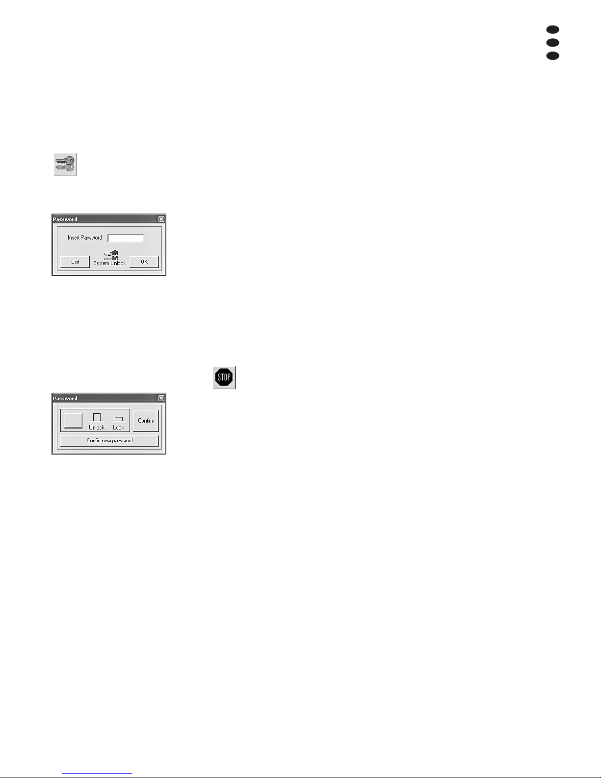
6.10 Passwort eingeben
Um das Gerät mit einem Passwort sperren zu
können oder das Passwort des Gerätes zu
ändern, ist es zunächst erforderlich, das aktuelle
Passwort einzugeben.
Hinweis: Im Auslieferungszustand und nach
dem Rücksetzen des Gerätes (
Kap. 5.7) gilt
folgendes Passwort:
000000
Um einen unbefugten Zugang zu erschweren,
sollte dieses Passwort unbedingt geändert werden (
Kap. 6.10.2).
Zur Eingabe des aktuellen Passwortes:
1) Auf die folgende Schaltfläche klicken.
Das Dialogfenster „Password –
Insert Password“ (
Abb. 25) öffnet
sich. Unter dem Schlüssel wird der
Zustand des Gerätes angezeigt:
„System Unlock“ – Gerät nicht gesperrt
„System Lock“ – Gerät gesperrt
2) In das Feld „Insert Password“ das aktuelle
Passwort eingeben und über die Schaltfläche
„OK“ bestätigen oder mit „Exit“ den Vorgang
abbrechen.
Nach der Eingabe des richtigen Passwortes
erscheint das Fenster „Password“ (
Abb.
26).
Bei Eingabe eines falschen Passwortes
erscheint die Meldung „Password incorrect“.
Nach Bestätigung der Meldung kann die Eingabe erneut erfolgen.
6.10.1 Gerät mit Passwort sperren
1) Nach der Eingabe des richtigen Passwortes
im Fenster „Password“ (Abb. 26) mit der
linken Schaltfläche das Gerät sperren oder
die Sperrung wieder aufheben.
Bei roter Schrift „Lock“ und roter Schaltfläche ist das Gerät gesperrt. Die Schrift
„Unlock“ ist rot bei aufgehobener Sperrung.
Bei gesperrtem Gerät ist keine Änderung der
Einstellungen möglich und von allen oberen
Schaltflächen im Hauptfenster sind nur noch
die zur Passworteingabe und zur Trennung
der Verbindung bedienbar. Auch nach dem
Trennen der Verbindung (
Kap. 6.11)
bleibt das Gerät gesperrt.
2) Zur Bestätigung auf die Schaltfläche „Confirm“ klicken.
6.10.2 Passwort ändern
1) Nach der Eingabe des aktuellen Passwortes
im Fenster „Password“ (
Abb. 26) auf die
Schaltfläche „Config new password“ klicken.
Das Fenster zur Eingabe des neuen Pass-
wortes öffnet sich.
2) In das Feld „Insert New Password“ das neue
Passwort eingeben und zur Bestätigung im
Feld „Confirm New Password“ wiederholen.
Ein Passwort kann aus max. 6 Zeichen
bestehen. Es können Groß- und Kleinbuchstaben aus dem ASCII-Zeichensatz, Ziffern
und Leerzeichen eingegeben werden.
Enthielt die Eingabe ungültige Zeichen,
erscheint die Meldung „Value passwords
incorrect“.
Stimmen die Eingaben in den beiden Feldern nicht überein, erscheint die Meldung
„Passwords donʼt match“.
Nach der Bestätigung einer Meldung kann
die Eingabe korrigiert werden.
3) Zum anschließenden Sperren oder Aufheben
der Sperrung in das sich öffnende Fenster
erneut das Passwort eingeben und mit „OK“
bestätigen oder den Vorgang mit „Exit“ ab brechen.
6.11 Verbindung trennen
Zum Trennen der Verbindung zwischen der PCSoftware und einem DSM-480LAN auf die folgende Schaltfläche klicken.
In dem sich öffnenden Dialogfenster „Do
you want to disconnect this device, are
you sure?“ das Vorhaben bestätigen
oder den Vorgang abbrechen.
Anschließend kann das DSM-480LAN wieder
direkt bedient werden.
7 Groundlift-Schalter
Zur Vermeidung von Brummstörungen durch
Masseschleifen ist das DSM-480LAN mit zwei
Massetrennschaltern ausgestattet.
Masseschleifen können entstehen, wenn
zwei Geräte sowohl über die Signalmasse als
auch über den Schutzleiter der Stromversorgung oder eine leitende Verbindung der
Gehäuse im Rack Kontakt haben.
Um die Signalmasse im Gerät von der
Gehäusemasse zu trennen, den Schalter MAIN
(14) in die Position LIFT stellen. Treten die
Brummstörungen nur in Verbindung mit der
Fernsteuerung über USB, RS-485 oder Ethernet
auf, kann die Masse dieser Schnittstellen von
der Signalmasse getrennt werden. Dazu den
Schalter INTERF. GND (15) in die Position LIFT
stellen.
8 Technische Daten
Frequenzbereich: . . . . . . . 20 – 20000 Hz
±1 dB
Analogeingänge
Eingangsspannung: . . . max. 7,75 V
Impedanz: . . . . . . . . . . . 25 kΩ
Anschlüsse: . . . . . . . . . . XLR, sym.
Digitaleingänge
Schnittstelle: . . . . . . . . . S/ PDIF
Abtastraten: . . . . . . . . . . 32/44,1/48 kHz
Anschluss: . . . . . . . . . . . Cinch
Ausgänge
Ausgangsspannung: . . . max. 7,75 V
Impedanz: . . . . . . . . . . . 150 Ω
Anschlüsse: . . . . . . . . . . XLR, sym.
Störabstand: . . . . . . . . . . . > 110 dB
Klirrfaktor: . . . . . . . . . . . . . < 0,005 %
A / D- und D /A-Wandler
Quantisierung: . . . . . . . . 24 Bit
Abtastrate: . . . . . . . . . . . 48kHz
Effektprozessor
DSP-Typ: . . . . . . . . . . . 2 × SAM3716
Datenformat: . . . . . . . . . 24 Bit (Daten)
× 96 Bit (Koeffizien-
ten)
Stromversorgung: . . . . . . . 230 V~ / 50Hz
Leistungsaufnahme: . . . . . max. 50 VA
Einsatztemperatur: . . . . . . 0 – 40 °C
Abmessungen (B × H × T): 482 × 44 × 230mm,
1 HE (Höheneinheit)
Gewicht: . . . . . . . . . . . . . . 2,5 kg
Änderungen vorbehalten.
㉖
Fenster „Password“
㉕
Fenster „Insert Password“
D
A
CH
21
Diese Bedienungsanleitung ist urheberrechtlich für MONACOR
®
INTERNATIONAL GmbH & Co. KG
geschützt. Eine Reproduktion für eigene kommerzielle Zwecke – auch auszugsweise – ist untersagt.
Page 22

22
GB
Contents
1 Operating Elements
and Connections . . . . . . . . . . . . . . . . 22
1.1 Front side . . . . . . . . . . . . . . . . . . . . . . . 22
1.2 Rear side . . . . . . . . . . . . . . . . . . . . . . . 23
2 Safety Notes . . . . . . . . . . . . . . . . . . . . 23
3 Applications . . . . . . . . . . . . . . . . . . . . 23
4 Setting up and Connecting the Unit .23
4.1 Signal sources . . . . . . . . . . . . . . . . . . . 23
4.2 Amplifier . . . . . . . . . . . . . . . . . . . . . . . . 24
4.3 Computer . . . . . . . . . . . . . . . . . . . . . . . 24
4.4 Mains connection . . . . . . . . . . . . . . . . . 24
5 Operation . . . . . . . . . . . . . . . . . . . . . . 24
5.1 Switching on / off . . . . . . . . . . . . . . . . . . 24
5.2 System settings (System Utilities) . . . . 24
5.2.1 Unit for signal delay . . . . . . . . . . . . . . . 24
5.2.2 Displaying the firmware version . . . . . . 24
5.3 Configuring inputs . . . . . . . . . . . . . . . . 24
5.3.1 Muting an input and
selecting it for the adjustment . . . . . . . 24
5.3.2 Selecting a signal source . . . . . . . . . . . 24
5.3.3 Noise Gate . . . . . . . . . . . . . . . . . . . . . . 24
5.3.4 Adjusting the amplification (Gain) . . . . 24
5.3.5 Adjusting the delay (Delay) . . . . . . . . . 25
5.3.6 Adjusting the sound control
(EQ 1 to 5) . . . . . . . . . . . . . . . . . . . . . . 25
5.3.6.1 Bypass . . . . . . . . . . . . . . . . . . . . . . 25
5.3.6.2 Selecting the filter type . . . . . . . . . . 25
5.3.6.3 Changing filter parameters . . . . . . . 26
5.4 Configuring outputs . . . . . . . . . . . . . . . 26
5.4.1 Muting an output and
selecting it for the adjustment . . . . . . . 26
5.4.2 Changing the name . . . . . . . . . . . . . . . 26
5.4.3 Selecting the input signal (Source) . . . 26
5.4.4 Adjusting the delay (Delay) . . . . . . . . . 26
5.4.5 High pass filter and low pass filter . . . . 26
5.4.6 Adjusting the sound control
(EQ 1 to 7) . . . . . . . . . . . . . . . . . . . . . . 28
5.4.6.1 Bypass . . . . . . . . . . . . . . . . . . . . . . 28
5.4.6.2 Selecting the filter type . . . . . . . . . . 28
5.4.6.3 Changing filter parameters . . . . . . . 28
5.4.7 Compressor (Compressor) . . . . . . . . . 28
5.4.8 Adjusting the amplification (Gain) . . . . 29
5.4.9 Level limitation (Limiter) . . . . . . . . . . . . 29
5.4.10 Phase reversal (Polarity) . . . . . . . . . . 29
5.4.11 LED indication (Vu-Meter) . . . . . . . . . 29
5.5 Configuration memory
(Program Utilities) . . . . . . . . . . . . . . . . 29
5.5.1 Memorizing a configuration . . . . . . . . . 29
5.5.2 Loading a configuration . . . . . . . . . . . . 29
5.5.3 Deleting a configuration . . . . . . . . . . . . 30
5.5.4 Memory chip card
5.6 Security adjustments
(Security Utilities) . . . . . . . . . . . . . . . . . 30
5.6.1 Concealing parameters . . . . . . . . . . . . 30
5.6.2 Locking the unit . . . . . . . . . . . . . . . . . . 30
5.6.2.1 Unlocking the unit . . . . . . . . . . . . . . 30
5.6.3 Locking the unit with a password . . . . . 30
5.6.3.1 Changing a password . . . . . . . . . . . 30
5.6.3.2 Locking the unit . . . . . . . . . . . . . . . . 30
5.6.3.3 Unlocking the unit . . . . . . . . . . . . . . 31
5.7 Reset of the unit . . . . . . . . . . . . . . . . . . 31
6 Remote Operation via a Computer . . 31
6.1 Installing the PC software . . . . . . . . . . 31
6.1.1 Installing the USB driver . . . . . . . . . . . 31
6.2 Selecting the interface . . . . . . . . . . . . . 31
6.3 Starting the PC software . . . . . . . . . . . 31
6.4 Views . . . . . . . . . . . . . . . . . . . . . . . . . . 32
6.4.1 View “Overview” . . . . . . . . . . . . . . . . . . 32
6.4.1.1 Selecting a signal source
6.4.2 View “Delays” . . . . . . . . . . . . . . . . . . . . 32
6.4.2.1 Unit for signal delay . . . . . . . . . . . . 32
6.4.3 View “Gains” . . . . . . . . . . . . . . . . . . . . 32
6.4.3.1 Phase reversal (Phase) . . . . . . . . . 32
6.4.3.2 LED indication (Vu-Meter Mode) . . 32
6.4.4 View of an input channel . . . . . . . . . . . 32
6.4.4.1 Gain . . . . . . . . . . . . . . . . . . . . . . . . 33
6.4.4.2 Muting . . . . . . . . . . . . . . . . . . . . . . . 33
6.4.4.3 Signal delay . . . . . . . . . . . . . . . . . . 33
6.4.4.4 Sound control . . . . . . . . . . . . . . . . . 33
6.4.4.5 Frequency response . . . . . . . . . . . . 34
6.4.4.6 Noise Gate
6.4.5 View of an output channel . . . . . . . . . . 34
6.4.5.1 Muting . . . . . . . . . . . . . . . . . . . . . . . 34
6.4.5.2 Selecting the input signals . . . . . . . 34
6.4.5.3 Signal delay . . . . . . . . . . . . . . . . . . 34
6.4.5.4 High pass filter and low pass filter . 34
6.4.5.5 Sound control . . . . . . . . . . . . . . . . . 34
6.4.5.6 Frequency response . . . . . . . . . . . . 34
6.4.5.7 Compressor . . . . . . . . . . . . . . . . . . 34
6.4.5.8 Gain . . . . . . . . . . . . . . . . . . . . . . . . 35
6.4.5.9 Level limitation (Limiter) . . . . . . . . . 35
6.4.5.10 Phase reversal . . . . . . . . . . . . . . . . 35
6.4.6 Linking the channels . . . . . . . . . . . . . . 35
6.5 Copying adjustments . . . . . . . . . . . . . . 36
6.5.1 Copying adjustments of an input . . . . . 36
6.5.2 Copying adjustments of an output . . . . 36
6.6 Renaming outputs . . . . . . . . . . . . . . . . 36
6.7 Renaming the unit . . . . . . . . . . . . . . . . 36
6.8 Administration of the configurations . . . 36
6.8.1 Saving the configuration
on the computer . . . . . . . . . . . . . . . . . . 36
6.8.2 Loading a configuration
from the computer . . . . . . . . . . . . . . . . 36
6.8.3 Memorizing the configuration
in the unit . . . . . . . . . . . . . . . . . . . . . . . 36
6.8.4 Loading a configuration
from the unit . . . . . . . . . . . . . . . . . . . . . 37
6.8.5 Configurations on the memory card . . . 37
6.8.6 Administrating configurations
as a project . . . . . . . . . . . . . . . . . . . . . 37
6.8.6.1 Compiling a project . . . . . . . . . . . . . 37
6.8.6.2 Memorizing the project . . . . . . . . . . 37
6.8.6.3 Loading a project . . . . . . . . . . . . . . 37
6.8.6.4 Transferring the project to the unit . 38
6.8.6.5 Loading a project from the unit . . . . 38
6.8.6.6 Project administration
with memory card . . . . . . . . . . . . . . 38
6.9 Locking the unit . . . . . . . . . . . . . . . . . . 38
6.10 Entering a password . . . . . . . . . . . . . . 38
6.10.1 Locking the unit with a password . . . . 38
6.10.2 Changing a password . . . . . . . . . . . . 38
6.11 Separating the connection . . . . . . . . . . 38
7 Groundlift switches . . . . . . . . . . . . . . 39
8 Specifications . . . . . . . . . . . . . . . . . . 39
All operating elements and connections de scribed can be found on the fold-out page 3.
1 Operating Elements
and Connections
1.1 Front side
1 LC display
2 Rotary knob PM1/ ENTER to select the menu
items, to select the parameters and to
change values;
press the knob to call a selected submenu
and to confirm an input.
3 Slot to accept the memory chip card
(
chapter 5.5.4)
4 Rotary knob PM2 / ESC to change adjust-
ments, depending on the selected submenu
item;
press the knob to cancel an input and to exit
a submenu.
5 Rotary knob PM3 / UTILITY to change adjust-
ments, depending on the selected submenu
item;
press the button to call the menu for general
system adjustments
6 Button EDIT/ MUTE for the selection or dese-
lection of an input or output to change its
adjustments or to mute it
button pressed for a while (approx. 2 s):
The input or output is muted or the sound is
reactivated [the LED (7) shows red during
muting]
button pressed shortly:
The input or output is selected or deselected
[the LED (7) shows blue when the input or
output is selected]
To make adjustments for several outputs
together, further outputs can be selected in
addition to an output already selected. It is
possible to deselect these outputs individually. The deselection of the first output
selected results in the deselection of all outputs. The adjustment of several inputs can be
linked in the same way. Then only the parameters changed during linking are adapted. All
individual adjustments of the inputs and outputs are maintained.
7 Status LED EDIT/ MUTE, each for the inputs
A to D and for the outputs 1 to 8, shows that
the input or output has been selected to
change its adjustments (shows blue) or / and
indicates muting of the input or output (shows
red)
8 LED chain, respectively for all inputs, to indi-
cate the input signal level;
if the LED CLIP lights up, the input is overloaded, in this case attenuate the output level
of the signal source accordingly
9 LED chain, respectively for the outputs 1 to 8,
to show the signal level or the attenuation of
the dynamic range, depending on the adjustment “Vu-Meter Mode” of the output
LIMIT
lights up when the limiter or the compressor
Page 23
is active and attenuates the dynamic range of
the output signal
“Vu-Meter Mode” = “Level”
The lower five LEDs show (according to the
imprint) the absolute output level. If the LED
CLIP lights up, the output is overloaded. In
this case reduce the level by attenuation of
the amplification (gain) for this output. The
LED CLIP may also light up if an overload
occurs for the sound control in case of
extreme filter adjustments.
“Vu-Meter” = “Limiter Act”
The lower five LEDs show, from top to bottom, the level attenuation by the limiter. For
this kind of display the LED CLIP lights up
continuously and does not show the overload
of the output.
“Vu-Meter” = “RMS Cmp Act”
The lower five LEDs show, from top to bottom, the level attenuation by the compressor.
For this kind of display the LED CLIP lights up
continuously and does not show the overload
of the output.
10 USB jack, type B, to connect a computer for
remote control of the DSM-480LAN.
1.2 Rear side
11 POWER switch
12 Mains jack for connection to a socket
(230 V~ / 50Hz) via the supplied mains cable
13 Support for the mains fuse;
only replace a blown fuse by a fuse of the
same type
14 Ground separating switch MAIN GND for the
audio connections:
GND
signal ground and housing ground are connected
LIFT
signal ground and housing ground are separated (groundlift)
15 Ground separating switch INTERF. GND for
the interfaces for control of the unit via a computer:
GND
signal ground and housing ground are connected
LIFT
signal ground and housing ground are separated (groundlift)
16 LAN port RJ45 for connection of a computer
for remote control of the DSM-480LAN; both
LEDs above the jack indicate the connection
set-up and the data transfer
17 RJ45 jack RS485 IN for connection of a com-
puter for remote control
18 RJ45 jack RS485 OUT for connection of
another unit to be controlled in case of
remote control by a computer via the jack
RS485 IN (17)
19 Inputs S/PDIF 1 and S/PDIF 2 as RCA jacks,
for connection of digital audio signal sources
20 Balanced audio signal outputs OUTPUT 1
to 8 as XLR jacks
21 Balanced audio signal inputs INPUT A to D
as XLR jacks for connection of analog signal
sources
2 Safety Notes
The unit corresponds to all relevant directives of
the EU and is therefore marked with .
It is essential to observe the following items:
The unit is suitable for indoor use only. Protect
it against dripping water and splash water,
high air humidity, and heat (admissible ambient temperature range 0 – 40°C).
Do not place any vessels filled with liquid, e. g.
drinking glasses, on the unit.
The heat being generated in the unit must be
carried off by air circulation. Therefore, the air
vents must not be covered.
Do not set the unit into operation, and immediately disconnect the mains plug from the
mains socket if
1. there is visible damage to the unit or to the
mains cable,
2. a defect might have occurred after a drop or
similar accident,
3. malfunctions occur.
The unit must in any case be repaired by
skilled personnel.
Never pull the mains cable to disconnect the
mains plug from the mains socket, always
seize the plug.
For cleaning only use a dry, soft cloth, never
use chemicals or water.
No guarantee claims for the unit and no liability for any resulting personal damage or material damage will be accepted if the unit is used
for other purposes than originally intended, if it
is not correctly connected or operated, or not
repaired in an expert way. Likewise, no liability will be accepted for data loss caused by
operating errors or by a defect and for any
consequential damage of this data loss.
Important for U. K. Customers!
The wires in this mains lead are coloured in
accordance with the following code:
green / yellow = earth
blue = neutral
brown = live
As the colours of the wires in the mains lead of
this appliance may not correspond with the
coloured markings identifying the terminals in
your plug, proceed as follows:
1. The wire which is coloured green and yellow must be connected to the terminal in the
plug which is marked with the letter E or by
the earth symbol
, or coloured green or
green and yellow.
2. The wire which is coloured blue must be
connected to the terminal which is marked
with the letter N or coloured black.
3. The wire which is coloured brown must be
connected to the terminal which is marked
with the letter L or coloured red.
Warning – This appliance must be earthed.
3 Applications
The DSM-480LAN is a digital signal processor
with four inputs (analog or digital) and eight outputs. It is provided as a link between a mixer and
the power amplifiers of a PA system and combines the functions of crossover networks, equalizers, delays, compressors and limiters. Due to
its versatile possibilities of configuration it can be
used in most different speaker arrangements.
24 configurations can each be memorized in
the unit and on the supplied memory chip card
and recalled, if required. Via the supplied software the DSM-480LAN can in addition be conveniently remote-controlled via a computer. The
computer is connected via the USB interface,
Ethernet or an RS-485 data bus. Up to 32 units
can be controlled via Ethernet or RS-485.
The following adjustments are possible for each
input channel:
– gain [
-
18...+18 dB]
– signal source: analog input, digital input or a
test signal generated internally (white noise/
pink noise)
– Noise Gate
– parametric equalizer with 5 filters
(17 filter types each for selection)
– delay [max. 849 ms], to be entered as an indi-
cation of time (ms) or distance (m)
– muting
The following adjustments are possible for each
output channel:
– assignment to an input signal or to the mixed
signal of several inputs
– high pass filter and low pass filter with 17 fil-
ter characteristics of different slopes to create
crossover networks
– parametric equalizer with 7 filters
(17 filter types each for selection)
– delay [max. 849 ms], to be entered as an indi-
cation of time (ms) or distance (m)
– compressor
– gain [
-
18…+18 dB]
– peak limiter [
-
10…+20 dBu]
– phase reversal
– muting
4 Setting up and
Connecting the Unit
The DSM-480LAN is provided for rack mounting
(482 mm / 19″) but it can also be used as a tabletop unit. For rack installation 1 rack space is
required (rs = rack space = 44.45 mm).
Prior to connecting or changing existing connections switch off the DSM-480LAN and the units
to be connected.
4.1 Signal sources
Connect analog signal sources with line level,
e. g. the output of a preamplifier or a mixer, to the
XLR jacks INPUTS A to D (21). The jacks are
provided for balanced signals; the contact configuration is shown in figure 2. For connection of
sources with unbalanced signals use adapters
with the XLR contacts 1 and 3 bridged.
Connect digital signal sources with an output
according to the S / PDIF standard to the jacks
S / PDIF (19). Analog and digital input signals can
only be alternatively processed per input channel (selecting a signal source,
chapter 5.3.2).
If the unit is to be put out of operation
definitively, take it to a local recycling
plant for a disposal which will not be
harmful to the environment.
WARNING The unit is supplied with haz-
ardous mains voltage. Leave servicing to skilled personnel only. Do
not insert anything through the air
vents. Inexpert handling or modification of the unit may cause an
electric shock hazard.
23
GB
Page 24
4.2 Amplifier
Connect the power amplifiers or units for further
signal processing to the XLR connections OUTPUTS (20).
4.3 Computer
For remote control of the DSM-480LAN via a
computer, connect the computer via a USB
cable to the jack (10).
Alternatively, the unit may be controlled via
the RS-485 interface or Ethernet. For connection
via RS-485 connect the RS-485 output of the
computer to the jack RS-485 IN (17); the contact
configuration is shown in figure 2. The output
jack RS-485 OUT (18) may be connected to the
jack RS-485 IN of another DSM-480LAN in each
case. Thus, up to 32 units to be controlled may
be connected in a chain. If several units are connected and longer control lines are used, the
control output of the last unit of the chain should
be provided with a terminating resistor (120 Ω
resistor between pins 1 and 2 of the connection)
to prevent interference during signal transmission.
For remote control of the unit by Ethernet
(TCP/ IP) the DSM-480LAN may be connected
via its jack RJ45 (16) to a single computer, a
local computer network or, e. g. via a router, to
larger computer networks. Up to 32 units may be
addressed in a network. For the correct settingup, knowledge of network technology is indispensable.
Hint: For a direct Ethernet connection to a computer a
crossover cable is required.
4.4 Mains connection
Connect the supplied mains cable to the mains
jack (12) and the mains plug to a socket (230 V~/
50 Hz).
5 Operation
5.1 Switching on / off
Prior to switching on the connected power amplifiers, connect the DSM-480LAN with the
POWER switch (11). The adjustments of the last
operation are loaded and the name of the last
configuration loaded from the memory is shown.
After use, switch off the unit with the POWER
switch. All adjustments will be maintained.
5.2 System settings (System Utilities)
The DSM-480LAN is adjusted via a menu in the
display (1). The menu is called for the general
system settings by pressing the knob UTILITY
(5), the menus for the adjustment of the inputs
and outputs are called by the selection of the
input or output with the corresponding button
EDIT/ MUTE (6). To navigate through the menu
and to change the adjustments, press the knobs
ENTER (2), ESC (4) and turn the knob PM1 (2).
A menu item can be selected with the rotary
knob PM1/ ENTER; press this knob to call the
submenu or to confirm an input. Press the knob
ESC to return to the higher menu level without
accepting a change. To change parameters, turn
the two knobs PM2 (4) and PM3 (5). If the display shows
*
behind an option, this corresponds
to the present adjustment.
An overview of the menu “UTILITY” is shown
in figure 3 on page 3.
5.2.1 Unit for signal delay
The signals of all inputs and outputs can individually be delayed. This is e. g. useful if speakers
are placed at different distances from the listeners. To balance the delay time of the sound, the
signal of the speaker located nearby is delayed
so that it does not reach the listener earlier than
the signal of the speaker located far away.
To spare the user the trouble of calculating
the delay time of the sound, the delay can alternatively be entered not only as a time indication
but also as a distance. The device calculates
with a sound speed of 340 m / s.
1) Press the knob UTILITY (5) to call the menu.
System Utilities
is displayed.
2) To call this submenu, press the knob ENTER
(2).
Delay Units
is displayed.
3) To call this submenu, press the knob ENTER
(2).
4) Use the rotary knob PM2 (4) to define if the
delay values are to be entered as a time indication (
Unit : Time (ms)
) or as a dis-
tance (
Unit : Distance(m)
) and confirm the selection by pressing the knob
ENTER.
5) To exit the menu, press the knob ESC (4)
twice. It is also possible to directly go to the
adjustment of an input or output with one of
the buttons EDIT/ MUTE (6).
5.2.2 Displaying the firmware version
To display the version of the firmware (operating
software of the DSM-480LAN):
1) Press the knob UTILITY (5) to call the menu.
System Utilities
is shown.
2) To call this submenu, press the knob ENTER
(2).
Delay Units
is shown.
3) Use the rotary knob PM1/ ENTER (2) to select
the menu item
Software Version
and
press the knob to confirm.
The version number is shown, e. g.
Version : V1.06
4) To exit the menu, press the knob ESC (4)
three times. It is also possible to directly go to
the adjustment of an input or output with one
of the buttons EDIT/ MUTE (6).
5.3 Configuring inputs
The signals of the inputs can already be
processed before they are distributed to the outputs. They run through the processing chain
shown in fig. 4.
5.3.1 Muting an input and
selecting it for the adjustment
Each input can be muted and also be selected
for the change of adjustments with the button
EDIT/ MUTE (6) below its level indication.
Press button for a while (approx. 2 s):
The input is muted or the sound is reactivated. If an input is muted, the LED (7) above
the button shows red.
Press button shortly:
The input is selected or deselected. If an
input is selected, the LED above the button
shows blue.
To make adjustments for several inputs
together, in addition to the input already
selected, further inputs can be selected.
These inputs can be deselected again. If the
first input selected is deselected, all inputs
are deselected. Only the parameters
changed during linking are adapted. All individual adjustments of the inputs are maintained.
When selecting an input, the display (1) shows
the last menu item called for this input in the
menu of the input adjustments (
fig. 5). The
menu items are selected and the adjustments
are changed with the knobs PM1/ ENTER (2),
PM2 / ESC (4) and PM3 (5).
5.3.2 Selecting a signal source
The unit has inputs for analog (21) and digital
(19) signals which can each be used alternatively. For test purposes it is possible to select a
signal generated in the unit (white noise or pink
noise) instead of an input signal.
1) Select an input with its button EDIT/ MUTE
(6).
2) Select the menu item
Source
with the
rotary knob RM1/ ENTER and press the knob
to confirm. The present adjustment is shown
(e. g.
ƊSource = Analog
).
3) Adjust the desired signal source with the
rotary knob PM2. A change is effective immediately.
Caution when switching over the test signals!
They used the full dynamic power and can be
of considerably higher volume than the signal
at the input.
Analog
analog input
Digital
digital input
Input A = S/PDIF 1, channel 1
Input B = S/PDIF 1, channel 2
Input C = S/PDIF 2, channel 1
Input D = S/PDIF 2, channel 2
White Noise
Pink Noise
4) To exit the submenu, press the knob ESC.
5.3.3 Noise Gate
A Noise Gate may be activated for each input.
Thus, low interfering noise whose level is below
the adjusted threshold value is suppressed in
signal intervals.
1) Select an input with its button EDIT/ MUTE
(6).
2) Select the menu item
N Gate
with the rotary
knob PM1/ ENTER and press the knob to
confirm. The present adjustment is shown.
(e. g.
ƊNoise Gate = Off
).
3) Activate (
On
) or deactivate (
Off
) the noise
suppression with the rotary knob PM2. A
change is effective immediately.
4) To exit the submenu, press the knob ESC.
Note: The operating parameters Threshold,
Attack and Release for the Noise Gate can only
be changed by computer via the supplied control
programme (chapter 6.4.4.6).
5.3.4 Adjusting the amplification (Gain)
The level of an input signal may be adapted via
the adjustment of the gain in the range
-
18 dB
up to +18 dB.
1) Select an input with its button EDIT/ MUTE
(6).
2) Select the menu item
Gain
with the rotary
knob PM1/ ENTER and press the knob to
confirm. The present adjustment is shown
(e. g.
ƊGain = 0.0dB
).
CAUTION The DSM-480LAN offers very flex-
ible possibilities of configuration.
For example, an output configured
for controlling a tweeter may
become the bass frequency out-
put in another configuration.
To prevent any overload of the speakers, prior
to switching on the power amplifiers, always
check if the configuration loaded of the DSM480LAN corresponds to the speaker constellation connected.
24
GB
Page 25

3) Adjust the desired gain with the rotary knob
PM2. A change is effective immediately.
4) To exit the submenu, press the knob ESC.
5.3.5 Adjusting the delay (Delay)
Each input signal may be delayed up to 848 ms.
Thus, e. g. differences in the sound delay times
for different speaker distances may be balanced.
1) Select an input with its button EDIT/ MUTE
(6).
2) Select the menu item
Delay
with the rotary
knob PM1/ ENTER and press the knob to
confirm.
The present adjustment is shown, e. g.
ƊDelay = 100.1040ms
It depends on the submenu “Delay Units” in
the menu for the general system adjustments
if the delay is stated as a time indication (
ms
)
or as a distance (
m
)[chapter 5.2.1].
3) Adjust the desired delay with the rotary knobs
PM2 [coarse] and PM3 [fine]. A change is
effective immediately.
4) To exit the submenu, press the knob ESC.
5.3.6 Adjusting the sound control (EQ 1 to 5)
Each input has 5 filters which can be adjusted
independently from each other. Via the function
EQ Bypass all filters of the input may be
bypassed.
1) Select an input with its button EDIT/ MUTE
(6).
2) Select the menu item
EQ Byp
with the rotary
knob PM1/ ENTER and press the knob to
confirm. The present adjustment is shown.
3) Use the rotary knob PM2 to define if the
filters of this channel are to be effective
(
ƊEQ Bypass = Off
) or bypassed (
ƊEQ
Bypass = On
). A change is effective imme-
diately.
4) To exit the submenu, press the knob ESC.
For each of the 5 filters (
EQ-1
to
EQ-5
) the following parameters may be adjusted. The deactivation of the function described above (
EQ
Bypass = Off
) is a prerequisite for the
change of these parameters. Otherwise a note
on this subject will appear when calling one of
the following submenu items.
5.3.6.1 Bypass
This function allows to bypass the selected filter.
1) Select an input with its button EDIT/ MUTE
(6).
2) Select the desired filter (
EQ-1
to
EQ-5
) with
the rotary knob PM1/ ENTER and press the
knob to confirm. The present adjustment is
shown, e. g.
ƊByp=Off
3) Use the rotary knob PM2 to define if the
selected filter is to be effective (
ƊByp=Off
)
or bypassed (
ƊByp=On
). A change is effec-
tive immediately.
4) To exit the submenu, press the knob ESC.
With active bypass function (
Byp=On
) it will not
be possible to change the other parameters of
this filter.
5.3.6.2 Selecting the filter type
17 filter types with different characteristics are
available. To change the filter type:
1) Select an input with its button EDIT/ MUTE
(6).
2) Select the desired filter (
EQ-1
to
EQ-5
) with
the rotary knob PM1/ ENTER and press the
knob to confirm. The present adjustment is
shown, e. g.
Input-A EQ-1 Ƅ
ƊByp=Off Type=Peaking_Eq
In addition to the filter type (
Peaking_Eq
)
a symbol for its characteristic (Ƅ) is shown on
the top right.
3) Select the filter type with the rotary knob
PM3. A change is effective immediately.
The following filter types are available:
Ƅ Peaking_Eq
(Peaking Equalizer)
filter with bell characteristic with adjustable
gain / attenuation, mid-frequency and quality
factor
ƃ Hi-Shelv_
(High Shelving Filter 1)
high frequency filter of first order with shelving characteristic
The level at the adjustable cut-off frequency
is 3 dB below/above the adjusted gain/attenuation; the slope is 6 dB / octave.
ƃ Hi-Shelv_2
(High Shelving Filter 2)
high frequency filter of second order with
shelving characteristic
The level at the adjustable cut-off frequency
is 3 dB below/ above the adjusted gain/attenuation; the slope is 12 dB / octave.
ƃ Hi-Shelv_Q
(High Shelving Filter Q)
symmetric high frequency filter with shelving
characteristic.
The level at the adjustable cut-off frequency
is half of the adjusted gain / attenuation; the
slope depends on the adjustable quality factor.
Ƃ Lo-Shelv_1
(Low Shelving Filter 1)
low frequency filter of first order with shelving
characteristic
The level at the adjustable cut-off frequency
is 3 dB below/above the adjusted gain/attenuation; the slope is 6 dB / octave.
Ƃ Lo-Shelv_2
(Low Shelving Filter 2)
low frequency filter of second order with
shelving characteristic
The level at the adjustable cut-off frequency
is 3 dB below/above the adjusted gain/attenuation; the slope is 12 dB / octave.
Ƃ Lo-Shelv_Q
(Low Shelving Filter Q)
symmetric low frequency filter with shelving
characteristic
The level at the adjustable cut-off frequency is
half of the adjusted gain / attenuation; the
slope depends on the adjustable quality factor.
Ɓ Low Pass_1
(Low Pass Filter 1)
low pass filter of first order with an attenuation of 3 dB at the cut-off frequency and a
slope of 6 dB / octave
Ɓ Low Pass_2
(Low Pass Filter 2)
low pass filter of second order with an attenuation of 3 dB at the cut-off frequency and a
slope of 12 dB / octave
25
GB
④
Block diagram of an input channel
⑤
Menu structure for the adjustment of an input channel
Page 26

Ɓ Low Pass_Q
(Low Pass Filter Q)
low pass filter with variable quality factor
ƀ HighPass_1
(High Pass Filter 1)
high pass filter of first order with an attenuation of 3 dB at the cut-off frequency and a
slope of 6 dB / octave
ƀ HighPass_2
(High Pass Filter 2)
high pass filter of second order with an attenuation of 3 dB at the cut-off frequency and a
slope of 12 dB / octave
ƀ HighPass_Q
(High Pass Filter Q)
high pass filter with variable quality factor
ƅ All Pass_1
(All Pass Filter 1)
All pass filter with constant magnitude frequency response and a phase shift of 90° at
the adjustable frequency.
ƅ All Pass_2
(All Pass Filter 2)
All pass filter with constant magnitude frequency response and a phase shift of 180° at
the adjustable frequency.
Ƅ Band Pass
(Band Pass Filter)
band pass filter with a passband around the
adjustable frequency. The bandwidth is
defined by the adjustable quality factor.
Ƅ Notch Filt
(Notch Filter)
notch filter for narrow-band attenuation of the
level around the adjustable frequency.
The rate of the attenuation is defined by the
adjustable quality factor.
5.3.6.3 Changing filter parameters
1) Select an input with its button EDIT/ MUTE
(6).
2) Use the rotary knob PM1/ ENTER to select
the desired filter (
EQ-1
to
EQ-5
) and press
the knob to confirm. The present adjustment
is shown, e. g.
Input-A EQ-1 Ƅ
ƊByp=Off Type=Peaking_Eq
3) Press the knob ENTER. The present filter
parameters are now shown, e. g.
Ɗ 1000Hz +11.5dB Q=1.1
i. e. mid-frequency = 1000 Hz,
gain = 11.5 dB, filter quality factor = 1.1
Note: The availability of a parameter depends
on the filter type selected.
4) Adjust the frequency with the rotary knob
PM1/ ENTER. A change is effective immediately.
For faster frequency changes, press the
knob. The lower line of the display now
shows e. g.:
ƊEdit Freq = 1000Hz
The frequency can now purposefully be
changed with the rotary knobs PM1 in steps
of 100 Hz, PM2 in steps of 10 Hz and PM3 in
steps of 1 Hz. To return to the higher menu
level, press the knob ESC.
5) Adjust the gain / attenuation with the rotary
knob PM2.
6) Adjust the filter quality factor with the rotary
knob PM3. A change is effective immediately.
To return to the next higher menu level, press
the knob ESC. To exit the adjusting menu, press
the knob ESC repeatedly or deselect the input
selected first.
5.4 Configuring outputs
The signals of all outputs run through the processing chain shown in fig. 6.
5.4.1 Muting an output and
selecting it for the adjustment
Each output can both be muted and selected for
the change of adjustments with the button EDIT/
MUTE (6) below its level indication.
Press button for a while (approx. 2 s):
The output is muted or the sound is reactivated. With the output muted, the LED (7)
above the button shows red.
Press button shortly:
The output is selected or deselected. When
the output is selected, the LED above the button shows blue.
To make adjustments for several outputs
together, further outputs can be selected in
addition to the output already selected.
These outputs can be deselected again. If the
first output selected is deselected, all outputs
are deselected. Only the parameters
changed during linking are adapted. All individual adjustments of the outputs are maintained.
When selecting an output, the display (1) shows
the last menu item called for this output in the
menu of the output adjustments (
fig. 7). The
menu items are selected and the adjustments
are changed with the knobs PM1/ ENTER (2),
PM2 / ESC (4) and PM3 (5).
5.4.2 Changing the name
The names of the outputs are factory-set to
“Out-1” to “Out-8”. These names can be
changed for each configuration to indicate e. g.
the place or the function of the speakers.
1) Select an output with its button EDIT/ MUTE
(6).
2) Use the rotary knob PM1/ ENTER to select
the menu item
Name
and press the knob to
confirm. The present name is shown, e. g.
ƊName = Low-A
The first character of the name flashes.
3) Use the rotary knob PM2 to change the flash-
ing character. Select the next character to be
changed with the rotary knob PM1 in each
case.
The name of an output may consist of
6 characters as a maximum.
4) To accept the change, press the knob
ENTER. To maintain the old name, press the
knob ESC.
Note: If several outputs are selected, only the
name of the output selected first is changed with
this function.
5.4.3 Selecting the input signal (Source)
Any desired combination of the four input chan-
nels can be assigned to each output. Each of the
input signals in the mixed signal for this output
can be attenuated up to 30 dB.
1) Select an output with its button EDIT/ MUTE
(6).
2) Use the rotary knob PM1/ ENTER to select
the menu item
Source
. The present
assignment is shown, e. g.
A:00 B:--- C:-30 D:---
i. e. the signals of the input channels A and C
are fed to the output, the level of C is attenuated by 30 dB.
3) To change the adjustment, press the knob
ENTER. The display shows now:
ƊIn-A Mute=Off Val=00
4) Use the rotary knob PM1/ ENTER to select
the input channel in each case. (
In-A
to
In-D
).
Use the rotary knob PM2 to select if the
signal of this input is to be fed to the output
(
Mute=Off
) or not (
Mute=On
).
Use the rotary knob PM3 to attenuate the
signal (for this output only). Adjustments from
Val=00
(0 dB gain, i. e. no attenuation) up
to
Val=-30
(i. e. 30 dB attenuation) are
possible.
A change is effective immediately.
5) To exit the submenu, press the knob ESC.
5.4.4 Adjusting the delay (Delay)
Each output signal may be delayed up to 848 ms.
Thus, e. g. differences in the delay times of the
sound for different speaker distances can be balanced. If a delay has already been adjusted in
the input signal assigned, the times are added.
1) Select an output with its button EDIT/ MUTE
(6).
2) Use the rotary knob PM1/ ENTER to select
the menu item
Delay
and press the knob to
confirm.
The present adjustment is shown, e. g.
ƊDelay = 100.1040ms
It depends on the submenu “Delay Units” in
the menu for general system adjustments if
the delay is entered as a time indication (ms)
or as a distance (m)[chapter 5.2.1].
3) Use the rotary knobs PM2 [coarse] and PM3
[fine] to adjust the desired delay. A change is
effective immediately.
4) To exit the submenu, press the knob ESC.
5.4.5 High pass filter and low pass filter
Each output has a high pass filter and a low pass
filter which as a combination primarily achieve
the function of a crossover network (for frequency-depending distribution of an input signal
to two or several output channels).
1) Select an output with its button EDIT/ MUTE
(6).
2) To adjust the high pass filter, use the rotary
knob PM1/ ENTER to select the menu item
HPF ƀ
and press the knob to confirm.
The present adjustment is shown, e. g.
ƊBessel_2nd F = 100Hz
i. e. filter characteristic: Bessel, 2ndorder, cutoff frequency =100 Hz
3) Use the rotary knob PM2 to select one of
17 filter characteristics or
Bypass
to bypass
the filter. A change is effective immediately.
The following filter characteristics are avail-
able:
Buttw_1st
Butterworth filter of first order with a slope of
6 dB / octave
Buttw_2nd
Butterworth filter of second order with a slope
of 12 dB / octave
LRiley_2nd
Linkwitz-Riley filter of second order with a
slope of 12 dB / octave
26
GB
⑥
Block diagram of an output channel
Page 27

Bessel_2nd
Bessel filter of second order with a slope of
12 dB / octave
Buttw_3rd
Butterworth filter of third order with a slope of
18 dB / octave
Buttw_4th
Butterworth filter of fourth order with a slope
of 24 dB / octave
LRiley_4th
Linkwitz-Riley filter of fourth order with a
slope of 24 dB / octave
Bessel_4th
Bessel filter of fourth order with a slope of
24 dB / octave
LRiley_6th
Linkwitz-Riley filter of 6th order with a slope
of 36 dB / octave
LRiley_8th
Linkwitz-Riley filter of 8th order with a slope
of 48 dB / octave
Custom_2nd
filter of second order with variable quality factor (Q), slope of 12 dB / octave
Custom_3rd
two cascaded filters with separately ad justable cut-off frequencies and variable
quality factor (Q) for the second filter, slope of
18 dB / octave
Custom_4th
two cascaded filters with separately ad justable cut-off frequencies and variable
quality factor (Q) for both filters, slope of
24 dB / octave
Custom_5th
three cascaded filters with separately ad justable cut-off frequencies and variable
quality factor (Q) for two filters, slope of
30 dB / octave
Custom_6th
three cascaded filters with separately
adjustable cut-off frequencies and variable
quality factor (Q) for all filters, slope of 36 dB/
octave
Custom_7th
four cascaded filters with separately
adjustable cut-off frequencies and variable
quality factor (Q) for three filters, slope of 42
dB / octave
Custom_8th
four cascaded filters with separately ad justable cut-off frequencies and variable
quality factor (Q) for all filters, slope of 48 dB/
octave
4) Use the rotary knob PM3 to adjust the frequency. A change is effective immediately.
For making major frequency changes faster,
press the knob ENTER. The lower line of the
display now shows e. g.:
ƊEdit Freq = 100Hz
The frequency can now purposefully be
changed with the rotary knobs PM1 in steps
of 100 Hz, PM2 in steps of 10 Hz and PM3 in
steps of 1 Hz. To return to the higher menu
level, press the knob ESC.
5) For the filter characteristics “Custom...”: to
adjust the additional parameters depending
on the filter order, use the rotary knob PM1 to
select the individual filters
Filt1
to
Filt4
, e. g.
ƊFilt1 F = 100Hz Q= 0.80
The parameters can be changed according to
the rotary knobs PM2 and PM3. A change is
effective immediately.
27
GB
⑦
Menu structure for the adjustment of an output channel
Page 28

Proceed as in step 4) for a fast frequency
change.
6) To exit the submenu, press the knob ESC.
7) The low pass filter can be adjusted in the
same way. For this purpose call the menu
item
LPF Ɓ
in step 2).
5.4.6 Adjusting the sound control (EQ 1 to 7)
In addition to the high pass filter and low pass filter, each output has 7 filters which can be
adjusted independently. Via the function EQ
Bypass these filters can completely be balanced.
1) Select an output with its button EDIT/ MUTE
(6).
2) Use the rotary knob PM1/ ENTER to select
the menu item
EQ Byp
and press the knob to
confirm. The present adjustment is shown.
3) Use the rotary knob PM2 to define if the
filters of this channel are to be effective
(
ƊEQ Bypass = Off
) or bypassed (
ƊEQ
Bypass = On
). A change is effective imme-
diately.
4) To exit the submenu, press the knob ESC.
For each of the 7 filters (
EQ-1
to
EQ-7
) the
following parameters may be adjusted. The
deactivation of the function described above (
EQ
Bypass = Off
) is a prerequisite for the
change of these parameters. Otherwise a note
on this subject will appear when calling one of
the following submenu items.
5.4.6.1 Bypass
This function only allows to bypass the filter
selected.
1) Select an output with its button EDIT/ MUTE
(6).
2) Use the rotary knob PM1/ ENTER to select
the desired filter (
EQ-1
to
EQ-7
) and press
the knob to confirm. The present adjustment
is shown, e. g.
ƊByp=Off
3) Use the rotary knob PM2 to define if the
selected filter is to be effective (
ƊByp=Off)
or bypassed (
ƊByp=On
). A change is effec-
tive immediately.
4) To exit the submenu, press the knob ESC.
With active bypass function (
Byp=On
) it is not
possible to change the other parameters of this
filter.
5.4.6.2 Selecting the filter type
17 filter types with different characteristics are
available. To change the filter type:
1) Select an output with its button EDIT/ MUTE
(6).
2) Use the rotary knob PM1/ ENTER to select
the desired filter (
EQ-1
to
EQ-7
) and press
the knob to confirm. The present adjustment
is shown, e. g.
Out-1 Low-A EQ-1 Ƅ
ƊByp=Off Type=Peaking_Eq
In addition to the filter type (
Peaking_Eq
)
a symbol for its characteristic (Ƅ) is shown on
the top right:
3) Select the filter type with the rotary knob
PM3. A change is effective immediately.
The following filter types can be selected:
Ƅ Peaking_Eq
(Peaking Equalizer)
filter with bell characteristic with adjustable
gain / attenuation, mid-frequency and quality
factor
ƃ Hi-Shelv_1
(High Shelving Filter 1)
high frequency filter of first order with shelving characteristic
The level at the adjustable cut-off frequency
is 3 dB below/ above the adjusted gain / attenuation; the slope is 6 dB / octave.
ƃ Hi-Shelv_2
(High Shelving Filter 2)
high frequency filter of second order with
shelving characteristic
The level at the adjustable cut-off frequency
is 3 dB below/ above the adjusted gain / attenuation; the slope is 12 dB / octave.
ƃ Hi-Shelv_Q
(High Shelving Filter Q)
symmetric high frequency filter with shelving
characteristic.
The level at the adjustable cut-off frequency
is half of the adjusted gain / attenuation; the
slope depends on the adjustable quality factor.
Ƃ Lo-Shelv_1
(Low Shelving Filter 1)
low frequency filter of first order with shelving
characteristic
The level at the adjustable cut-off frequency
is 3 dB below/ above the adjusted gain / attenuation; the slope is 6 dB / octave.
Ƃ Lo-Shelv_2
(Low Shelving Filter 2)
low frequency filter of second order with
shelving characteristic
The level at the adjustable cut-off frequency
is 3 dB below/ above the adjusted gain / attenuation; the slope is 12 dB / octave.
Ƃ Lo-Shelv_Q
(Low Shelving Filter Q)
symmetric low frequency filter with shelving
characteristic
The level at the adjustable cut-off frequency
is half of the adjusted gain / attenuation; the
slope depends on the adjustable quality factor.
Ɓ Low Pass_1
(Low Pass Filter 1)
low pass filter of first order with an attenuation of 3 dB at the cut-off frequency and a
slope of 6 dB / octave
Ɓ Low Pass_2
(Low Pass Filter 2)
low pass filter of second order with an attenuation of 3 dB at the cut-off frequency and a
slope of 12 dB / octave
Ɓ Low Pass_Q
(Low Pass Filter Q)
low pass filter with variable quality factor
ƀ HighPass_1
(High Pass Filter 1)
high pass filter of first order with an attenuation of 3 dB at the cut-off frequency and a
slope of 6 dB / octave
ƀ HighPass_2
(High Pass Filter 2)
high pass filter of second order with an attenuation of 3 dB at the cut-off frequency and a
slope of 12 dB / octave
ƀ HighPass_Q
(High Pass Filter Q)
high pass filter with variable quality factor
ƅ All Pass_1
(All Pass Filter 1)
All pass filter with constant magnitude frequency response and a phase shift of 90° for
the adjustable frequency.
ƅ All Pass_2
(All Pass Filter 2)
All pass filter with constant magnitude frequency response and a phase shift of 180°
for the adjustable frequency.
Ƅ Band Pass
(Band Pass Filter)
band pass filter with a passband around the
adjustable frequency. The bandwidth is
defined by the adjustable quality factor.
Ƅ Notch Fil
(Notch Filter)
notch filter for narrow-band attenuation of the
level around the adjustable frequency.
The rate of the attenuation is defined by the
adjustable quality factor.
5.4.6.3 Changing filter parameters
1) Select an output with its button EDIT/ MUTE
(6).
2) Use the rotary knob PM1/ ENTER to select
the desired filter (
EQ-1
to
EQ-7
) and press
the knob to confirm. The present adjustment
is shown, e. g.
Out-1 Low-A EQ-1 Ƅ
ƊByp=Off Type=Peaking_Eq
3) Press the knob ENTER. The present filter
parameters are now shown, e. g.
Ɗ 1000Hz +11.5dB Q=1.1
i. e. mid-frequency = 1000 Hz,
gain = 11.5 dB, filter quality factor = 1.1
Note: The availability of a parameter depends
on the filter type selected.
4) Adjust the frequency with the rotary knob
PM1/ ENTER. A change is effective immediately.
For faster frequency changes, press the
knob. The lower line of the display now
shows e. g.:
ƊEdit Frequ = 1000Hz
The frequency can now purposefully be
changed with the rotary knobs PM1 in steps
of 100 Hz, PM2 in steps of 10 Hz and PM3 in
steps of 1 Hz. To return to the higher menu
level, press the knob ESC.
5) Adjust the gain / attenuation with the rotary
knob PM2.
6) Adjust the filter quality factor with the rotary
knob PM3. A change is effective immediately.
To return to the next higher menu level, press
the knob ESC. To exit the adjusting menu, press
the knob ESC repeatedly or deselect the output
selected first.
5.4.7 Compressor (Compressor)
The compressor reduces the dynamic range and
attenuates the level above an adjustable threshold. This is necessary if the dynamic range of the
audio signal is higher than allowed by the amplifier system or the listening situation (e. g. in case
of background music). It is also possible to
reduce level differences (e. g. for changing
microphone distances) or to attenuate signal
peaks in order to allow a higher gain setting and
thus to obtain a higher average volume.
The compressor responds to the effective
value (RMS) of the signal. The activity of the compressor is shown by the LED LIMIT of the output
indication (9). In addition, it is possible to show
the level reduction caused by the compressor
instead of the output level (
chapter 5.4.11).
1) Select an output with its button EDIT/ MUTE
(6).
2) The adjustments of the compressor are
divided into three menu items
RMS Cmp
.
Select the first of them with the rotary knob
PM1/ ENTER and press the knob to confirm.
The present adjustment is shown, e. g.
Out-1 Low-A RMS Cmp
ƊBypass = Off
3) Use the rotary knob PM2 to define if the compressor is to be used for this output
(
Bypass = Off
) or bypassed (
Bypass =
On
). A change is effective immediately.
4) To exit the submenu, press the knob ESC.
5) Use the rotary knob PM1/ ENTER to select
the next menu item and press the knob to
confirm.
The present adjustment is shown, e. g.
Out-1 Low-A RMS Cmp
ƊThr=+11.8dBu Rto=10:1
28
GB
Page 29

6) Use the rotary knob PM2 to adjust the threshold value. If this value is exceeded, the amplification is reduced. Use the control PM3 to
adjust the compression ratio. For example, a
compression ratio of
10:1
means that with
an input level increase of 20 dB above the
threshold value the output level will only be
increased by 2 dB.
7) To exit the submenu, press the knob ESC.
8) Use the rotary knob PM1/ ENTER to select
the next menu item and press the knob to
confirm.
The present adjustment is shown, e. g.
Out-1 Low-A RMS Cmp
ƊA= 50ms R=0.5s Kn= 00%
9) Use the rotary knob PM1 to adjust the attack
time. Use the rotary knob PM2 to adjust the
release time, i. e. the time until the amplification has reached its original value again in
case a level has fallen below the threshold
value. The control PM3 allows to define if the
change to compression is to be made
abruptly
Kn=00%
(Hard Knee) or with a tran-
sition range
Kn=100%
(Soft Knee) when the
threshold value is exceeded. The value
defines the size of the transition range.
10) To exit the submenu, press the knob ESC.
5.4.8 Adjusting the amplification (Gain)
The level of an output signal may be adapted via
the adjustment of the gain in the range -18 dB
up to +18 dB. A level attenuation caused by the
compressor can thus be balanced.
1) Select an output with its button EDIT/ MUTE
(6).
2) Select the menu item
Gain
with the rotary
knob PM1/ ENTER and press the knob to
confirm. The present adjustment is shown
(e. g.
ƊGain = 0.0dB
).
3) Adjust the desired gain with the rotary knob
PM2. A change is effective immediately.
4) To exit the submenu, press the knob ESC.
5.4.9 Level limitation (Limiter)
The limiter allows to quickly limit the signal to an
adjusted level. Thus, the power amplifiers are
protected against overload and the speakers are
protected against damage. It operates similar to
the compressor described before. However,
while the compressor still allows an increase of
the output level depending on the compression
rate adjusted, the threshold value of the limiter
defines the absolute upper limit of the output signal (compression ratio = ∞: 1).
The limiter responds to the peak values of
the signals. The activity of the limiter is shown by
the LED LIMIT of the output indication (9). In
addition, it is possible to show the level reduction
caused by the limiter instead of the output level
(
chapter 5.4.11).
1) Select an output with its button EDIT/ MUTE
(6).
2) The adjustments of the limiter are divided into
two menu items
Limiter
. Select the first of
them with the rotary knob PM1/ ENTER and
press the knob to confirm.
The present adjustment is shown, e. g.
Out-1 Low-A Limiter
ƊBypass = Off
3) Use the rotary knob PM2 to define if the limiter is to be used for this output (
Bypass =
Off
) or bypassed (
Bypass = On
). A
change is effective immediately.
4) To exit the submenu, press the knob ESC.
5) Use the rotary knob PM1/ ENTER to select
the next menu item and press the knob to
confirm.
The present adjustment is shown, e. g.
Out-1 Low-A Limiter
ƊA= 50ms R=50ms +10.4dBu
6) Use the rotary knob PM1 to adjust the attack
time, and the rotary knob PM2 to adjust the
release time, i. e. the time until the amplification has reached its original value again if the
level has fallen below the threshold value.
Use the rotary knob PM3 to adjust the threshold value, i. e. the output level admitted as a
maximum. If this value is exceeded, the
amplification is reduced.
7) To exit the submenu, press the knob ESC.
5.4.10 Phase reversal (Polarity)
The signal of an output may be inverted (phase
reversal), e. g. to balance a reverse polarity
when connecting the speakers.
1) Select an output with its button EDIT/ MUTE
(6).
2) Use the rotary knob PM1/ ENTER to select
the menu item
Polarity
and press the
knob to confirm.
The present adjustment is shown, e. g.
ƊPolarity = Normal
3) Use the rotary knob PM2 to define if the output signal is to be inverted (
Polarity =
Invert
) or not (
Polarity = Nor-
mal
). A change is effective immediately.
4) To exit the submenu, press the knob ESC.
5.4.11 LED indication (Vu-Meter)
The LED indication of each output can show the
level reduction by the compressor or limiter
instead of the output level. To select the type of
indication:
1) Select an output with its button EDIT/ MUTE
(6).
2) Use the rotary knob PM1/ ENTER to select
the menu item
Vu-Meter
and press the
knob to confirm.
The present adjustment is shown, e. g.
ƊVu-Meter = Level
3) Use the rotary knob PM2 to select the type of
indication:
Vu-Meter = Level
indication of output level (corresponding to the imprint)
If the LED CLIP lights up, the output
or a member of the processing chain
is overloaded. In these cases reduce
the amplification at the corresponding spot.
Vu-Meter = Limiter Act
indication of the level reduction by
the limiter (corresponding to the figure on the left)
The LED CLIP continuously lights up
with this type of indication (as a 0 dB
mark) and does not show an overload.
Vu-Meter = RMS Cmp Act
Indication of the level reduction by
the compressor (corresponding to
the figure on the left)
The LED CLIP continuously lights up
with this type of indication (as a 0 dB
mark) and does not show an overload.
Independent of the selected adjustment, the
LED LIMIT always lights up when the compressor or limiter limits the level.
4) To exit the submenu, press the knob ESC.
To exit the adjusting menu, press the knob
ESC repeatedly or deselect the output
selected first.
5.5 Configuration memory
(Program Utilities)
The adjustments made at the DSM-480LAN are
maintained after switching-off. In addition, there
is the possibility to memorize up to 24 configurations as “Program” in the unit. Not only the
adjustments made in the menus for the inputs
and outputs are memorized but also the muting
of the inputs and outputs.
It is also possible to access these configurations memorized in the unit by means of the
remote control of the DSM-480LAN via a computer (
chapter 6.8.4).
5.5.1 Memorizing a configuration
1) To call the menu, press the knob UTILITY (5).
System Utilities
is shown.
2) Use the rotary knob PM1/ ENTER (2) to
select the menu item
Program Utili-
ties
and press the knob to confirm.
3) Use the rotary knob PM1/ ENTER to select
the menu item
Save a Program
and
press the knob to confirm.
4) Use the rotary knob PM1/ ENTER to select
one of the 24 memory locations and press the
knob to confirm. To prevent overwriting one
of the configurations memorized, select a
free memory location (
Empty Program
).
As a prompt to enter a name the upper line
of the display shows:
Set Program Name
The first character of the previous name
flashes. To maintain the previous name, proceed with step 6).
5) Use the rotary knob PM2 to change the flash-
ing character. Use the rotary knob PM1 to
select the next character to be changed in
each case.
The name of a configuration may consist
of 16 characters as a maximum. Upper-case
letters and lower-case letters from the ASCII
character set, numerals as well as some special characters are available.
6) Stop entering the name by pressing the knob
ENTER. To memorize the configuration,
press the knob ENTER once again (or cancel
the procedure by pressing the knob ESC).
During memorizing, the display shows:
Saving to Memory....
7) To exit the submenu, press the knob ESC.
5.5.2 Loading a configuration
To load a configuration memorized before:
1) To call the menu, press the knob UTILITY (5).
System Utilities
is shown.
2) Use the rotary knob PM1/ ENTER (2) to
select the menu item
Program Utili-
ties
and press the knob to confirm.
3) To confirm the menu item
Recall a Pro-
gram,
press the knob ENTER. If no configu-
CAUTION
Prior to loading a configuration,
always check if it corresponds with
the speaker constellation con-
nected.
Due to the flexible possibilities of configuration
of the DSM-480LAN, e. g. an output configured
for controlling a tweeter may become the bass
frequency output after loading another configuration. In this case there is the risk of overload
for a tweeter connected to this output
29
GB
Page 30

ration has yet been memorized, the message
shortly appears:
No Stored Programs.
4) Use the rotary knob PM1/ ENTER to select
one of configurations memorized and press
the knob to confirm. To load the configuration
(indication:
[Enter] to Re call
), press
the knob ENTER once again (or cancel the
procedure by pressing the knob ESC).
During loading, the display shows:
Loading New Program....
5) To exit the submenu, press the knob ESC.
After exiting the menu, the name of the last con-
figuration loaded is displayed.
5.5.3 Deleting a configuration
To delete a configuration not required any more
from the memory of the DSM-480LAN:
1) To call the menu, press the knob UTILITY (5).
System Utilities
is shown.
2) Use the rotary knob PM1/ ENTER (2) to
select the menu item
Program Utili-
ties
and press the knob to confirm.
3) Use the rotary knob PM1/ ENTER to select
the menu item
Delete a Program
and
press the knob to confirm.
4) Use the rotary knob PM1/ ENTER to select
the memory location to be deleted and press
the knob to confirm. To delete the configuration (indication:
[Enter] to Delete
),
press the knob ENTER once again (or cancel
the procedure by pressing the knob ESC).
During deleting, the display shows:
Deleting Program....
5) To exit the submenu, press the knob ESC.
5.5.4 Memory chip card
As an extension of the memory locations in the
unit, for data back-up or for the transfer of configurations between two units it is possible to
memorize 24 configurations on the supplied
memory chip card. It is also possible to access
the card when the DSM-480LAN is remotely
controlled via a computer (
chapter 6.8.5).
1) Insert the card with the contacts showing
upwards into the slot PC CARD (3).
2) To call the menu, press the knob UTILITY (5).
System Utilities
is displayed.
3) Use the rotary knob PM1/ ENTER (2) to select
the menu item
Memory Card Utili-
ties
and press the knob to confirm.
4) As described for the internal storage in chapters 5.5.1 to 5.5.3, it is possible to memorize
a configuration on the card, to load a configuration from the card or to delete it via the
submenus
Save a Program
,
Recall a Program
,
Delete a Program.
If there is no card in the unit, the following
error message is shown:
Error: Card not inserted
5.6 Security adjustments
(Security Utilities)
The DSM-480LAN can be locked against accidental misadjustment and unauthorized operation. It is possible to define if the adjustments are
to be visible or concealed when the unit is
locked.
5.6.1 Concealing parameters
To define if the adjustments are to be visible or
concealed when the unit is locked:
1) To call the menu, press the knob UTILITY (5).
System Utilities
is shown.
2) Use the rotary knob PM1/ ENTER (2) to
select the menu item
Security Utili-
ties
and press the knob to confirm.
3) Confirm the menu item
Show Parameter
by pressing the knob ENTER.
4) Use the rotary knob PM2 (4) to define if the
adjustments are to be visible (
Parameter
will be shown
) or concealed (
Para-
meter will not be shown
) when the
unit is locked. The present adjustment is
marked *.
5) Confirm the selection by pressing the knob
ENTER or cancel the procedure by pressing
the knob ESC.
6) To exit the submenu, press the knob ESC.
5.6.2 Locking the unit
To lock the unit against accidental misadjustment:
1) To call the menu, press the knob UTILITY (5).
System Utilities
is shown.
2) Use the rotary knob PM1/ ENTER (2) to select
the menu item
Security Utilities
and press the knob to confirm.
3) Use the rotary knob PM1/ ENTER to select
the menu item
Lock Unit
and press the
knob to confirm. The display shows:
Lock : Off *
(unit not locked)
4) Use the rotary knob PM2 (4) to change the
adjustment to:
Lock : On
(lock the unit)
5) Confirm the selection by pressing the knob
ENTER or cancel the procedure by pressing
the knob ESC.
The display shows the symbol
Ƈ
for a unit locked
in this way. Now it is not possible any more to
change the adjustments or to mute inputs or outputs. It depends on the preadjustment “Show
Parameter” (
chapter 5.6.1) if the adjustments
for the inputs or outputs are visible.
5.6.2.1 Unlocking the unit
To unlock the unit:
1) Press the knob UTILITY (5). The display
shows:
Lock Unit
Lock : On *
2) Use the rotary knob PM2 (4) to select
Lock : Off
and press the knob ENTER to
confirm.
3) To exit the submenu, press the knob ESC.
5.6.3 Locking the unit with a password
The unit can be protected against unauthorized
operation with a password. When delivered and
after the reset of the unit (
chapter 5.7) the fol-
lowing password applies:
000000
To make an unauthorized access difficult, it is
indispensable to change this password.
5.6.3.1 Changing a password
1) To call the menu, press the knob UTILITY (5).
System Utilities
is shown.
2) Use the rotary knob PM1/ ENTER (2) to
select the menu item
Security Utili-
ties
and press the knob to confirm.
3) Use the rotary knob PM1/ ENTER to select
the menu item
User Password
and press
the knob to confirm. The display shows:
User Password
[_ ]
The flashing underscore marks the position
for inserting the first character.
4) Enter the present password:
Use the rotary knob PM2 to change the flashing character. Use the rotary knob PM1 to
select the position of the next character to be
entered in each case.
5) To terminate the input, press the knob
ENTER.
When entering an invalid password, the
following message appears:
Password Wrong!
In this case repeat the input from step 3).
When entering a valid password, the fol-
lowing message appears:
New Password
[_ ]
6) Enter the new password here and press the
knob ENTER to confirm. A password may
consist of 6 characters as a maximum.
Note: To make unlocking of the unit possible
even when the unit is remotely controlled via
a computer, the password should only consist of upper-case letters and lower-case letters from the ASCII character set, numbers
and blanks.
7) To exit the submenu, press the knob ESC.
5.6.3.2 Locking the unit
1) To call the menu, press the knob UTILITY (5).
System Utilities
is shown.
2) Use the rotary knob PM1/ ENTER (2) to
select the menu item
System Utili-
ties
and press the knob to confirm.
3) Use the rotary knob PM1/ ENTER to select
the menu item
Enable Password
and
press the knob to confirm. The display
shows:
Enable Password:
[_ ]
The flashing underscore marks the position
for inserting the first character.
4) Enter the password:
Change the flashing character with the rotary
knob PM2. Select in each case the position of
the next character to be entered with the
rotary knob PM1.
5) To terminate the input, press the knob
ENTER.
PC CARD
30
GB
Page 31

When an invalid password is entered, the
following message appears:
Password Wrong!
In this case repeat the input from step 3).
When the input is correct, the following
message appears:
Password : Disable *
(unit not locked)
6) Change the adjustment with the rotary knob
PM2 to
Password : Enable
(lock the unit with password)
and press the knob PM1/ ENTER to confirm.
The display shows the symbol
Ƈ
when a unit is
locked in this way. Now it is not possible any
more to change the adjustments or to mute
inputs or outputs. It depends on the preadjustment “Show Parameter” if the adjustments for the
inputs or outputs are visible (
chapter 5.6.1).
5.6.3.3 Unlocking the unit
To unlock the unit:
1) Press the knob UTILITY (5). The display
shows:
Enable Password:
[_ ]
The flashing underscore marks the position
for inserting the first character.
2) Enter the password:
Change the flashing character with the rotary
knob PM2. Select the position of the next
character to be entered with the rotary knob
PM1.
3) To terminate the input, press the knob
ENTER.
When an invalid password is entered, the
following message appears:
Password Wrong!
In this case repeat the input from step 1).
When the input is correct, the following
message appears:
Password : Enable *
4) Change the adjustment with the rotary knob
PM2 to
Password : Disable
and press the knob PM1/ ENTER to confirm.
5) To exit the submenu, press the knob ESC.
5.7 Reset of the unit
The unit can be reset to the factory settings.
Then all adjustments made by the user, including the memorized configurations, are lost irretrievably. To maintain these configurations (Programs), they have to be saved on a memory card
(chapter 5.5.4) or externally on a computer
(
chapter 6.8.6.5).
1) With the unit switched off, keep the knobs
ENTER (2), ESC (4) and UTILITY (5)
pressed at the same time and switch on the
unit with the POWER switch (11).
2) When the display shows the message
Doing Factory Reset
Please wait...........
release the knobs.
3) When after a few seconds the message
RESET MEMORY
Turn-off the device
appears, switch the unit off and on again.
All adjustments are now reset. The password
to lock the unit (
chapter 5.6.3) is again:
000000
6 Remote Operation
via a Computer
The DSM-480LAN may be remotely operated
via the supplied computer software. All adjustments can be made like via the menu of the unit,
however, the presentation is much more clearly
arranged. The filter adjustments can also be
made graphically by mouse and the resulting frequency responses and phases are shown as
curves. In addition, it is possible to change the
parameters of the Noise Gates, to copy adjustments between the channels, to save configurations on the computer and to administrate the
complete configuration memory as a project.
6.1 Installing the PC software
System requirements for the installation of the
supplied control programme are a PC with the
operating system Windows XP (SP2) or higher,
a working memory of 256 MB as a minimum,
50 MB free hard disk memory and a USB interface, Ethernet or RS-485 interface. The screen
resolution should be 1024 × 768 pixels as a minimum. For the installation of the PC software
start the installation programme SETUP.EXE on
the supplied CD and follow the instructions of the
installation programme.
Windows is a registered trademark of the Microsoft Corporation in the USA and
other countries.
6.1.1 Installing the USB driver
A special driver is required for connection via the
USB interface. This driver is available on the
supplied CD. For automatic installation of the
driver call the file USB[…]SETUP.EXE. The
driver simulates a serial interface for the operating software.
6.2 Selecting the interface
To switch over between the RS-485 interface,
the Ethernet interface and the USB connection:
1) To call the menu, press the knob UTILITY (5).
System Utilities
is shown.
2) Use the rotary knob PM1/ ENTER (2) to select
the menu item
Interface Utilities
and press the knob to confirm.
Interface
Setup
is shown.
3) Press the knob ENTER again.
4) Use the rotary knob PM2 (4) to define if the
USB interface (
Source : USB
), the RS-485
interface (
Source : RS485
) or the Ether-
net interface (
Source : TCP/IP
) is to be
used. The present adjustment is marked *.
5) Confirm the selection by pressing the knob
ENTER or cancel the procedure by pressing
the knob ESC (4).
6) When the RS-485 interface or the Ethernet
interface has been selected, additionally
define the unit number to distinguish several
units at the data bus:
Turn the rotary knob PM1 clockwise so that
the unit number is shown, e. g.:
Remote ID Num = 01 *
When controlled via the Ethernet interface,
the unit number is defined by the last two
digits of the IP address of the unit, e. g.:
IP ADDR = 192.168.0.101*
Use the rotary knob PM2 to adjust the
desired number (01to 32) and press the
knob ENTER to confirm.
7) To exit the adjusting menu, press the knob
ESC three times.
6.3 Starting the PC software
1) Start the control programme
DSM-480LAN Vx.x.EXE on the PC.
2) Select the desired interface (“USB”, “RS485”
or “TCP/ IP”) in the dialog window “Select”
under “Communication Port”.
3) If “USB” is selected (fig. 8), the serial interface which the driver simulates for the software has to be selected under “COM Select”.
It is possible to find the present COM interface in the adjustments of the operating system under Control Panel System Properties (Hardware) Device Manager Ports
(COM and LPT). It reads e. g.
If conflicts occur with other units, the number
of the COM interface can be changed here (via
Properties Port Settings Advanced …).
4) When “RS485” or “TCP/ IP” is selected
(
fig. 9), select under “Connection” if only
one DSM-480LAN or several units are to be
controlled:
1 DSM-480LAN “with one device”
2 – 32 DSM-480LAN “with several devices”
If “with one device” has been selected, in the
field “ID Select” or “IP Address” select the
number entered in the respective unit
(
chapter 6.2). If “with several devices” has
been selected, the program will automatically
find the unit numbers with the following step.
5) Confirm the selection by clicking the button
“Connect” (or exit the programme by clicking
“Exit”).
⑨
Window „Select Communication Port“ – TCP/ IP
⑧
Window „Select Communication Port“ – USB
31
GB
Page 32

The main window opens and after a short
time a list with the connected units appears
(
fig. 10).
The unit now displays:
PC Connection
System Lock
or for control via Ethernet e. g.:
PC Connection
IP Addr [192.168.0.101]
and cannot be operated directly as long as
the connection exists (to disconnect the connection chapter 6.11).
If it was not possible to make the connection to the units, an error message appears
and the start of the control programme without connection to a DSM-480LAN (Demo
mode) is offered.
By clicking “Yes” the programme starts in
the demo mode with one or several virtual
units “Device Demo” in the list.
By clicking “No” the programme is finished.
If no connection is made, this may be due to
the following causes:
– a wrong interface has been adjusted
(
chapter 6.2)
– the units are not correctly connected
– a unit is not switched on
– the network adjustments at the computer
are not correct (for connection via Ethernet)
6) By double-clicking a unit in the list “List ID”
(
fig. 10) a window opens which shows the
present configuration of this unit.
6.4 Views
In the window for each unit it is possible to switch
over the views presented as “tabs”: “Overview”,
“Delays”, “Gains” and the adjustments for each
input channel and output channel.
6.4.1 View “Overview”
This view (
fig. 11) offers a fast overview of
the configuration. It shows the four input channels on the left and the eight output channels on
the right. The lines in between represent the
assignment of the outputs to the inputs. This
assignment can be changed by clicking the
corresponding node points in the matrix display
on the top right. To change the mixing ratio of
the signals it is, however, required to change into
the view of the respective output channel
(
chapter 6.4.5.2).
The type of signal source can be selected for
each input channel per list field. The icon
shows the muting of an input channel or output
channel in each case.
6.4.1.1 Selecting a signal source
Via the list fields at the beginning of the four input
signal chains it is possible to select between the
analog input signal and the digital input signal in
each case. Besides, for test purposes, the two
signals generated internally “White noise” and
“Pink noise” are available for selection. This
adjustment corresponds to the menu item
Source
in the menu to configure an input
(chapter 5.3.2).
6.4.2 View “Delays”
This view (
fig. 12) offers an overview of the
delay adjustments of all inputs and outputs. In
addition, the assignment of the outputs to the
inputs is shown as lines. This assignment can be
changed by clicking the corresponding node
points in the matrix display on the top right. To
change the mixing ratio of the signals it is, however, required to change into the view of the
respective output channel (
chapter 6.4.5.2).
To change the delay values, click the arrows
next to the input fields: Make a coarse adjustment with the arrows above “Adj”, a fine adjustment with the arrows above “Fine”. Alternatively,
the value can also directly be entered into a field.
Then the number entered is rounded to the next
possible value.
When changing the values, it is possible to
link the inputs or outputs to facilitate the input of
the same values (
chapter 6.4.6).
6.4.2.1 Unit for signal delay
The unit for the signal delay may be selected
under “Units” as “Time” (time in ms) or “Meter”
(distance in m) [details
chapter 5.2.1]. This
adjustment changes the units for all delay times
of this device.
6.4.3 View “Gains”
This view (
fig. 13) offers an overview of the
gain adjustments of all input channels and output
channels. In addition, the muting of all channels
and the phase reversal and the LED indication
types of the outputs are shown.
To change the amplification of a channel,
move the corresponding control with the mouse
or, with a control selected, on the keyboard with
the arrow keys or the scrolling keys. To mute a
channel or to cancel the muting, click the button
“Mute” under the corresponding control. With the
channel muted, the button is red.
When changing the values, it is possible to
link the inputs or outputs to facilitate the input of
the same values (
chapter 6.4.6).
6.4.3.1 Phase reversal (Phase)
A tick in the field “Phase 180°” under the control
of an output channel indicates the phase reversal
of the output signal (compare “Polarity”
chap -
ter 5.4.10). To switch over, click the field.
6.4.3.2 LED indication (Vu-Meter Mode)
Under “Vu-Meter Mode” it is possible to select
the type of the LED indication for each output.
The options correspond to the following adjustments in the unit (
chapter 5.4.11).
“Level” =
Level
“Limiter” =
Limiter Act
“Compr” =
RMS Cmp Act
6.4.4 View of an input channel
This view (
fig. 14) offers a clearly arranged
presentation for all parameters of the corresponding input. When changing the values, it is possible to link the input channels to facilitate the
input of the same values for several input channels (chapter 6.4.6).
⑩
Unit list “List ID”
32
GB
⑪
View “Overview”
Page 33

6.4.4.1 Gain
Under “Gain” the input amplification can be
adjusted. To change the amplification, move the
control with the mouse or, with a control
selected, on the keyboard with the arrow keys or
the scrolling keys. This is the same parameter as
in the view “Gains” (
chapter 6.4.3).
6.4.4.2 Muting
As an alternative to muting in the view “Gains”
(
chapter 6.4.3) the input can be muted in this
view as well.
For muting or for cancelling the muting click
the button “Mute”. With the channel muted, the
button is red.
6.4.4.3 Signal delay
Under “Delay” the delay time for the input signal
can be adjusted. The unit (meter or milliseconds)
can be changed in the view “Delays” (
chap-
ter 6.4.2.1).
To change the delay value, click the arrows
under the input field: Make a coarse adjustment
with the arrows above “Adj”, a fine adjustment
with the arrows above “Fine”. Alternatively, the
value can also directly be entered into the field.
Then the number entered is rounded to the next
possible value. This is the same parameter as in
the view “Delays” (
chapter 6.4.2).
6.4.4.4 Sound control
Under “EQ” the 5 independent filters of the input
channel can be adjusted (
fig. 15).
1) Select the filter type via the upper
button (in this case “PEAK EQ”)
[description of the filter types
chapter 5.3.6.2]
2) Adjust the level boosting or attenuation with the sliding control.
3) Enter the filter frequency into the
field under the control.
4) Enter the filter quality factor (Q) or
the relative value for the bandwidth
(Bw) into the corresponding field or
adjust them by clicking the arrows
underneath the fields. A number
entered is rounded to the next possible value.
Note: The availability of a parameter depends on
the filter type selected.
5) By clicking the button “Byp”, the individual filter can be deactivated. Then the button is
red. To reactivate the filter, click the button
again.
6) To deactivate all filters of this input, click the
button “EQ Byp”. Then the button is red. To
reactivate the filters, click the button again.
7) To reset the amplification values of all filters
of this input, click the button “EQ Flat” and in
the dialog window “EQ Flat – Are you sure?”
which opens confirm or cancel the procedure.
Then all filters are deactivated and can be
reactivated by clicking the button “Byp”.
Note: Alternatively, the level boosting/attenuation and the filter frequency can also be adjusted
graphically (
chapter 6.4.4.5).
⑮
„EQ“
33
GB
⑫
View “Delays”
⑬
View “Gains”
⑭
View Input channel “In D” with window “Noise Gate Configuration”
Page 34

6.4.4.5 Frequency response
The upper range of the view shows the frequency response of the input channel, depending on the adjustment of the input amplification
and the sound control.
On the top right of the diagram it is possible
to select the presentation as a magnitude frequency response “Mag” or phase frequency
response “Phase”.
When the button “Show cursor” is clicked, a
graphical reference point (
, , , , )is
shown next to the curve for each filter (similar to fig. 16). By means of the mouse the filters
can now graphically be adjusted by moving
these points with regard to frequency and level
boosting / attenuation (if admitted by the filter
type selected).
When the button “Show cursor” is clicked
again, these reference points will disappear.
6.4.4.6 Noise Gate
To suppress low interfering noise in signal intervals, a Noise Gate is available in each input
channel.
In the list field select under “Noise Gate” if the
interfering suppression is to be activated (ON) or
not (OFF). To change the operating parameters
for the Noise Gate:
1) Click the button “Edit” next to the list field. The
window “Noise Gate Configuration” (
fig. 14)
opens and shows the Noise Gate parameters
for all inputs.
2) Click the arrows next to the input fields to
adjust the desired values.
“Threshold”: threshold value below which a
signal is suppressed
“Release”: release time during which a sig-
nal is still audible after falling
below the threshold value
“Attack”: attack time, defines the delay
between exceeding of the
threshold value and passingthrough of the signal
3) To memorize the changes made, click the
button “Store” and confirm the procedure in
the dialog window which opens “Upgrade
Noise Gate Configuration – Are you sure?” or
cancel the procedure.
4) Click the button “Exit” to extinguish the window “Noise Gate Configuration”.
6.4.5 View of an output channel
This view (
fig. 17) offers a clearly arranged
presentation for all parameters of the corresponding output. When changing the values, it is possible to link the output channels to facilitate the
input of the same values for several output channels (chapter 6.4.6).
6.4.5.1 Muting
As an alternative to muting in the view “Gains”
(
chapter 6.4.3) the output can also be muted
in this view.
To mute or to cancel the muting, click the
button “Mute”. With the channel muted, the button is red.
6.4.5.2 Selecting the input signals
Via the assignment matrix (on the top right)
select the input signals for the output channel.
Each line of the matrix represents an input channel, each column an output channel. Click a
node point to assign an input to an output (the
square at the node point is green) or cancel the
assignment. Under “Routing Mix” it is possible to
attenuate the level of each assigned input signal
by up to 30 dB using the sliding control (the
attenuation only applies to this output channel).
Thus, different signal mixings can be obtained
for the outputs. Via the button “Reset Routing”,
after confirming the safety prompt, all assignments are reset.
The channel assignment is shown in the
views “Overview” (fig. 11) and “Delays”
(fig. 12) by coloured lines and can there likewise be changed.
6.4.5.3 Signal delay
Under “Delay” the delay for the output signal
can be adjusted. The unit (meter or milliseconds)
can be changed in the view “Delays” (chapter 6.4.2.1).
To change the delay value, click the arrows
next to the input field: Make a coarse adjustment
with the arrows above “Adj”, a fine adjustment
with the arrows above “Fine”. Alternatively, the
value can also directly be entered into the field.
Then the number entered is rounded to the next
possible value.
This is the same parameter as in the view
“Delays” (chapter 6.4.2).
6.4.5.4 High pass filter and low pass filter
In combination, the high pass and low pass filters of the outputs should primarily fulfil the function of a crossover network for frequency-dependent distribution of one input signal to two or
several output channels. When adjusting the filters, it is useful that the frequency response of
several outputs can be shown in one diagram
(chapter 6.4.5.6).
1) To adjust the high pass filter, enter the cut-off
frequency in the field “Frequency [Hz]” under
“High Pass filter” and select from the list
“Slope” the filter characteristic or “Bypass” if
the filter is not to be used (details about the filter characteristic
chapter 5.4.5).
2) To adjust the low pass filter, enter the cut-off
frequency in the field “Frequency [Hz]” under
“Low Pass filter” and from the list “Slope”
select the filter characteristic or “Bypass” if
the filter is not to be used (details about the filter characteristic
chapter 5.4.5).
3) For the filter characteristics “Custom…” to
adjust additional parameters click one of the
two buttons “Edit”. Then the window “Edit
custom filter High / Low Pass …” (
fig. 18)
opens.
Contrary to the presentation of the frequency response in the main window of the
output channel (
chapter 6.4.5.6), in this
case only the change of the frequency
response by the high pass filter and low pass
filter is shown.
On the top right of the diagram it is possible to select the presentation of magnitude
frequency response “Mag” or phase frequency response “Phase”.
Depending on the filter characteristic
“Custom…” selected, additional input fields
for further parameters are inserted. Via the
buttons “ButtW” and “L-Riley” the filter characteristics Butterworth and Linkwitz-Riley
may be preset, if possible, as a basis for an
individual adjustment.
6.4.5.5 Sound control
Under “EQ” it is possible to adjust the 7 independent filters of the output channel, as already
described for the input channels (
chapter
6.4.4.4).
6.4.5.6 Frequency response
The upper range of the view shows the frequency response of the output channel, depending on the adjustment of the high pass and low
pass filters, the sound control and the output
amplification.
On the top right of the diagram it is possible
to select between the presentation of magnitude
frequency response “Mag” and phase frequency
response “Phase”.
The buttons below the diagram allow to
define if only the adjustments of the output channel “Output” are to be shown or also the adjustments of an input channel e. g. “Out + InA” are
to be considered for the presentation.
The curves of the other output channels
may in addition be inserted or extinguished on
the right next to the diagram via the buttons
named accordingly (
fig. 19). Thus, it can e. g.
be shown how the magnitude frequency
responses of the channels of a crossover network complete one another.
When the button “Show cursor” is clicked, a
graphical reference point (
, , , , , , )
is shown next to the curve (
fig. 16) for each
filter for the presentation of a magnitude frequency response. By means of the mouse the filters can now graphically be adjusted by moving
these points with regard to frequency and level
boosting / attenuation (if admitted by the filter
type selected).
When the button “Show cursor” is clicked
again, the reference points will disappear.
6.4.5.7 Compressor
To change the parameters of the compressor,
move the corresponding control under “RMS
Compressor” with the mouse or, with a control
selected, on the keyboard with the arrow keys or
the scrolling keys. (Details about the function
and the parameters of the compressor
chap-
ter 5.4.7)
To bypass the compressor or to reactivate it,
click the small box “Compressor bypass”. With
the tick placed, the compressor is deactivated.
When the button “View RMS Compressor” is
clicked, the window “RMS Compressor & Peak
34
GB
⑯
Filter curve with marks
Page 35

Limiter…” opens (fig. 20). It contains the
same controls for the parameters and the small
box “Bypass” to bypass the compressor. In addition, the signal level of the compressor input and
output is shown graphically depending on the
compressor adjustments. The effect of a change
of the parameters “Threshold”, “Ratio” or “Soft /
Hard Knee” is immediately visible in this case.
6.4.5.8 Gain
The level of the output signal may be adapted
under “Level” by adjusting the gain in the range
-
18 dB to +18 dB. A level reduction caused by
the compressor can also be balanced in this
way.
To change the gain, move the control with
the mouse or, with a control selected, on the keyboard with the arrow keys or the scrolling keys.
This is the same parameter as in the view
“Gains” (
chapter 6.4.3).
6.4.5.9 Level limitation (Limiter)
To change the limiter parameters under “Peak
Limiter”, move the corresponding control with
the mouse or, with a control selected, on the keyboard with the arrow keys or the scrolling keys.
(Details about the function and the parameters of
the limiter chapter 5.4.9)
To bypass the limiter or to reactivate it, click
the small box “Limiter bypass”. With the tick
placed, the limiter is deactivated.
When clicking the button “View Peak Limiter”, the window “RMS Compressor & Peak Limiter …” opens (
fig. 20). It contains the same
controls for the parameters and the small box
“Bypass” to bypass the limiter. In addition, the
signal level of the limiter input and of the output
is graphically shown depending on the limiter
adjustments. The effect of a change of the
parameter “Threshold” is visible immediately.
Below the curve the corresponding peak voltage
[Vp] is shown in addition to the maximum level
[dBu] adjusted via “Threshold”.
6.4.5.10 Phase reversal
A tick in the field “Phase 180°” shows the phase
reversal of the output signal (compare “Polarity”
chapter 5.4.10). To switch over, click the
field. This is the same parameter as in the view
“Gains” (
chapter 6.4.3.1).
6.4.6 Linking the channels
For the same adjustment of certain parameters
for several outputs or inputs it is possible to link
the inputs or outputs during the adjustment. The
parameters changed at one output are now identical for all outputs linked. Likewise, the adjustments made during the linking of the inputs are
made at the selected input channels at the same
time. Only the parameters changed during linking are adapted in each case. All individual
adjustments of the inputs or outputs are maintained.
⑳
Window “RMS Compressor & Peak Limiter”
35
GB
⑰
View output channel “Low-A”
⑱
Window “Edit custom filter ...”
⑲
Filter curve of several outputs
Page 36

To link the inputs:
1) At the lower edge of the window under “Input
Linked” click the buttons of all inputs whose
parameters are to be adjusted in the same
way. If the view for a special input is being
shown (
fig. 14), click the button for
this input as well. The buttons appear
“depressed” and the lettering becomes blue.
The linking is maintained even when
switching over to another view.
2) To release the linking for an input, click its
button again.
To link the outputs:
1) At the lower edge of the window under “Output Linked” click the buttons of all outputs
whose parameters are to be adjusted in the
same way. If the view for a special output is
being shown (
fig. 17), click the button for
this output as well. The buttons appear
“depressed” and the lettering becomes blue.
The linking is maintained even when
switching over to another view.
2) To release the linking for an output, click its
button again.
Linking has no effect on the functions “Mute”,
“Vu-Meter Mode”, the channel assignment
“Routing Mix” and the naming of the outputs.
6.5 Copying adjustments
Contrary to linking the channels when only the
parameters changed during linking are adapted,
the copying function transfers all adjustments of
a channel to another. The adjustments for
“Mute”, “Vu-Meter Mode”, the channel assignment “Routing Mix” and the naming of the outputs are not copied.
6.5.1 Copying adjustments of an input
1) Click the button “Input Copy”. The dialog window “Input copy channel” opens.
2) Under “Input Source” select the input whose
adjustments are to be transferred to another.
3) Under “Input Destination” select the input
which is to accept the adjustments.
4) Confirm the selection with “Confirm” or cancel the procedure with “Cancel”.
5) In another dialog window “Copy Input – Are
you sure?” confirm or cancel the procedure.
6.5.2 Copying adjustments of an output
1) Click the button “Output Copy”. The dialog
window “Output copy channel” opens.
2) Under “Output Source” select the output
whose adjustments are to be transferred to
another.
3) Under “Output Destination” select the output
which is to accept the adjustments.
4) Confirm the selection with “Confirm” or cancel the procedure with “Cancel”.
5) In another dialog window “Copy Output – Are
you sure?” confirm or cancel the procedure.
6.6 Renaming outputs
To rename the outputs, click the button
or the name of an input or output in the
view “Overview” (
fig. 11). The win-
dow “Edit Names” (
fig. 21) is
inserted. The names of the outputs
Out1 to Out8 can be changed here. A name may
consist of 6 characters as a maximum. It is
recommended to refrain from using special
(country-specific) characters (e. g. ä, ö, ü, ß, è, ô,
ì, á, ñ, μ) as they will not correctly be shown on
the display of the DSM-480LAN.
6.7 Renaming the unit
To rename the unit, click the following button.
The window “Name Device – Edit Name
Device” is inserted and the present
name of the unit may be changed. The
name may consist of 16 characters as a maximum and appears in the list “List ID” (
fig. 10).
When using several units, it serves to distinguish
them.
6.8 Administration of the configurations
Each configuration adjusted in the DSM-480LAN
may permanently be memorized on one of its
24 memory locations as “Program”. By means of
the control programme these configurations may
be read from the memory of the DSM-480LAN
and be saved on the computer or they can e. g.
be modified and retransferred to the unit.
6.8.1 Saving the configuration
on the computer
To save the present configuration on the computer:
1) Click the following button.
The dialog window opens “Save As”.
2) Enter the desired file name, select the mem-
ory location and save the file.
As a preset for the memory location, the
subfolder “Program” is selected which has
automatically been created during installation
of the programme. The file extension *.m48 is
automatically attached to the name entered.
6.8.2 Loading a configuration
from the computer
To load a configuration memorized on the computer:
1) Click the following button.
The dialog window
“Open” opens.
2) Select the desired file and confirm the open-
ing.
If the selected file does not contain any
valid configuration, the following message
appears “Load Program – File not admitted”.
6.8.3 Memorizing the configuration
in the unit
To memorize the present configuration in the
DSM-480LAN:
1) Click the following button.
The dialog window
“Store to Memory Program”
(
fig. 22) opens.
2) In the field “Select Position” or by double-
clicking an entry in the list, select the memory
location under “Memory Program”. A free
memory location “Program Empty” may be
selected or a memory location already
reserved may be selected to overwrite its
contents.
3) Enter the name for the configuration in the
field “Edit Name”. The name may consist of
16 characters as a maximum. It is recommended to refrain from using special (country-specific) characters (e. g. ä, ö, ü, ß, è, ô, ì,
á, ñ, μ) as they will not correctly be shown on
the display of the DSM-480LAN.
4) To store, click the button “Store” or cancel the
procedure with “Cancel”.
5) In another dialog window “Store Program –
Are you sure?” confirm or cancel the procedure.
After storing, the window “Store to Memory
Program” will be closed.
CAUTION
Prior to loading a configuration
check if it corresponds to the
speaker constellation connected.
Due to the flexible possibilities of configuration
of the DSM-480LAN, e. g. an output configured
for controlling a tweeter may become the bass
frequency output after loading another configuration. In this case there is the risk of overload
for a tweeter connected to this output.
㉑
Window “Edit Names”
36
GB
Page 37

6.8.4 Loading a configuration from the unit
To load a configuration from the memory of the
DSM-480LAN:
1) Click the following button.
The dialog window
“Read from Memory Program”
(
fig. 23) opens.
2) Select a configuration from the list under
“Memory Program”.
3) To load, click the button “Read” or cancel the
procedure with “Cancel”.
If a free memory location “Program Empty”
has been selected, an error message
appears.
4) In another dialog window “Read Memory Program – Overwriting current editing, are you
sure?” confirm or cancel the procedure.
After loading, the window “Read from
Memory Program” will be closed.
6.8.5 Configurations on the memory card
As described in chapter 6.8.3 for the storage of a
configuration in the unit, it is possible to write a
configuration on a memory chip card in the unit
via the button “Store to Memory-Card”.
Likewise, according to chapter 6.8.4, a configuration of a memory chip card in the unit may
be loaded to the computer via the button “Read
from Memory-Card”.
If there is no card in the unit, the following error
message appears: “Memory Card not present”.
6.8.6 Administrating configurations
as a project
In order to always prevent the individual transfer,
storage and loading of configurations, it is possible to combine up to 24 configurations (i. e. all
memory locations of the DSM-480LAN) to projects. A project can newly be complied of the individual configurations if these configurations
have already been memorized on the computer
(
chapter 6.8.1). Alternatively, all configurations of the memory of the DSM-480LAN or of
the memory card can be loaded as a project to
be memorized as a back-up copy on the computer or to serve as a basis for a new project.
6.8.6.1 Compiling a project
To compile a new project:
1) Click the button “Store Project”. The window
“Store Project” opens (
fig. 24).
2) Select the memory location in the field
“Select Position” or in the list under “Project
List”.
3) Via the button “Search Program” load a con-
figuration memorized on the computer.
4) Enter the name for the configuration in the
field “Edit Name Program”. The name may
consist of 16 characters as a maximum. It is
recommended to refrain from using special
(country-specific) characters (e. g. ä, ö, ü, ß,
è, ô, ì, á, ñ, μ) as they will not correctly be
shown on the display of the DSM-480LAN.
5) Add the configuration to the list via the button
“Add to Project List”.
6) Repeat the steps 2) to 5) until all desired con-
figurations are contained in the project.
7) To remove a configuration from the project
list, select its memory location in the field
“Select Position” or in the list under “Project
List” and click the button “Delete from Project
List”. In the dialog window opened “Delete
Program from the Project list, are you sure?”
confirm or cancel the procedure.
8) Prior to closing the window “Store Project”
store the project in any case (
chapter
6.8.6.2) otherwise it will be lost.
6.8.6.2 Memorizing the project
To store the project after the project has newly
been created or loaded from the memory of the
DSM-480LAN:
1) Click the button “Save Project to PC” in the
window “Store Project” (
fig. 24).
2) Enter the desired file name, select the memory location and store the file.
As a preset for the memory location, the
subfolder “Project” created automatically during programme installation is selected. The
file extension *.prj is automatically attached
to the name entered.
6.8.6.3 Loading a project
To load a project memorized on the computer:
1) Click the button “Store Project”. The window
“Store Project” opens (
fig. 24).
2) Click the button “Search Project”. The dialog
window “Open” opens.
3) Select the desired project file and confirm the
opening.
In the window “Store Project” under “Project Name” the file name and the memory
location of the project loaded are present
now.
CAUTION
Prior to loading a configuration in
any case check if it corresponds to
the speaker constellation con-
nected.
Due to the flexible possibilities of configuration
of the DSM-480LAN, e. g. an output configured
for controlling a tweeter may become the bass
frequency output after loading another configuration. In this case there is the risk of overload
for a tweeter connected to this output.
37
GB
㉒
Window “Store to Memory Program”
㉓
Window “Read from Memory Program”
Page 38

6.8.6.4 Transferring the project to the unit
A project can completely be transferred to the
memory of the DSM-480LAN. The previous
memory contents are overwritten. For free positions of the project list “-----“ the contents of the
corresponding memory location in the unit
remain unchanged. Thus, it is possible to complete or exchange only some configurations in
the unit.
To transfer the present project to the memory of
the DSM-480LAN:
1) In the window “Store Project” (
fig. 24) click
the button “Store Project to Device”.
2) In the dialog window which opens “Store current project to device, are you sure?” confirm
or cancel the procedure.
After successful transfer the message
“Project stored on the device” appears.
6.8.6.5 Loading a project from the unit
To load the complete configuration memory of
the DSM-480LAN as a project into the computer:
1) Click the button “Read Project from Device”
in the window “Store Project” (
fig. 24).
2) In the dialog window opened “Read current
project from device - are you sure?” confirm
or cancel the procedure.
The progress of the transfer is shown in
the window “Store Project” at the bottom.
After loading, “Device project” can be found
under “Project Name” as a source of the project
loaded. The project can now e. g. be saved
on the computer (
chapter 6.8.6.2) or, as
described under “Compiling project” (chapter 6.8.6.1), be completed with memorized configurations and then retransferred to the unit
(chapter 6.8.6.4).
6.8.6.6 Project administration with memory card
The preceding chapters describe the storage
and loading of a project from the memory of the
unit to the PC. It is possible to administrate projects from the PC to the memory card in the same
way via the button “Store Project to MemoryCard”.
For the storage of configurations from a
memory card as a project, an individual folder
“CardProject” is created on the PC. However,
also other memory locations can be selected.
6.9 Locking the unit
As described in chapter 5.6.2, the unit may be
locked against accidental misadjustment. This is
also possible via the control programme:
1) Click the following button.
The button now appears with a red
frame and the operation is locked.
After separating the connection (
chapter
6.11) the unit remains locked.
2) To unlock, click the button again.
6.10 Entering a password
To be able to lock the unit with a password or to
change the password of the unit, it is required to
enter the present password first.
Note: When delivered and after the reset of the
unit (
chapter 5.7), the following password
applies:
000000
To make an unauthorized access difficult, this
password should be changed in any case
(
chapter 6.10.2).
To enter the present password:
1) Click the following button.
The dialog window “Password –
Insert Password” (
fig. 25) opens.
The state of the unit is shown under
the key:
“System Unlock” – unit not locked
“System Lock” – unit locked
2) Enter the present password into the field
“Insert Password“ and confirm via the button
“OK” or cancel the procedure with “Exit“.
After entering the correct password, the
window “Password” appears (
fig. 26).
When entering a wrong password the
message “Password incorrect” appears.
After confirming the message the input may
be made once again.
6.10.1 Locking the unit with a password
1) After entering the correct password in the
window “Password” (
fig. 26), lock the unit
with the left button or unlock it.
With the red lettering “Lock” and red button
the unit is locked. The lettering “Unlock” is red
when the unit is unlocked.
With the unit locked, no change of the adjustments is possible. All upper buttons in the
main window cannot be operated except for
the button for password input and the button
for separating the connection. Even after
separating the connection (
chapter 6.11)
the unit remains locked.
2) To confirm, click the button “Confirm”.
6.10.2 Changing a password
1) After entering the present password in the
window “Password” (
fig. 26), click the but-
ton “Config new password”.
The window to enter the new password
opens.
2) Enter the new password into the field “Insert
New Password” and repeat it in the field
“Confirm New Password” to confirm. A password may consist of 6 characters as a maximum. Upper-case letters and lower-case letters from the ASCII character set, numbers
and blanks may be entered.
If the input contains invalid characters, the
message “Value passwords incorrect” ap pears.
If the inputs in both fields are not in accordance with each other, the message “Passwords donʼt match” appears.
After confirmation of a message the input
may be corrected.
3) For subsequent locking or unlocking, enter
the password again into the window opened
and confirm with “OK” or cancel the procedure with “Exit”.
6.11 Separating the connection
To separate the connection between the PC
software and a DSM-480LAN, click the following
button.
In the dialog window which opens
“Do you want to disconnect this device,
are you sure?” confirm or cancel the
procedure.
Then the DSM-480LAN can directly be operated
again.
㉖
Window “Password”
㉕
Window “Insert Password”
38
GB
㉔
Window “Store Project”
Page 39

39
GB
All rights reserved by MONACOR®INTERNATIONAL GmbH & Co. KG. No part of this instruction
manual may be reproduced in any form or by any means for any commercial use.
7 Groundlift switches
To prevent hum interference by ground loops,
the DSM-480LAN is equipped with two ground
separating switches.
Ground loops may occur if two units have
contact with each other both via the signal
ground and via the protective conductor of the
power supply or a conductive connection of the
housings in the rack.
To separate the signal ground in the unit
from the housing ground, set the switch MAIN
(14) to position LIFT. If hum interference only
occur in connection with the remote control via
USB, RS-485 or Ethernet, the ground of these
interfaces may be separated from the signal
ground. For this purpose set the switch
INTERF. GND (15) to position LIFT.
8 Specifications
Frequency range: . . . . . . . 20 – 20 000Hz
±1 dB
Analog inputs
input voltage: . . . . . . . . . max. 7.75 V
impedance: . . . . . . . . . . 25 kΩ
connections: . . . . . . . . . XLR, bal.
Digital inputs
interface: . . . . . . . . . . . . S / PDIF
sampling rates: . . . . . . . 32 / 44.1 / 48 kHz
connection: . . . . . . . . . . phono
Outputs
output voltage: . . . . . . . max. 7.75 V
impedance: . . . . . . . . . . 150 Ω
connections: . . . . . . . . . XLR, bal.
S / N ratio: . . . . . . . . . . . . . . > 110 dB
THD: . . . . . . . . . . . . . . . . . < 0.005 %
A / D and D /A converters
quantization: . . . . . . . . . 24 bits
sampling rate: . . . . . . . . 48 kHz
Effect processor
DSP type: . . . . . . . . . . . 2 × SAM3716
data format: . . . . . . . . . . 24 bits (data)
× 96 bits (coefficients)
Power supply: . . . . . . . . . . 230 V~ / 50 Hz
Power consumption: . . . . . max. 50 VA
Ambient temperature: . . . . 0 – 40°C
Dimensions (W × H × D): . 482 × 44× 230 mm,
1 rs (rack space)
Weight: . . . . . . . . . . . . . . . 2.5 kg
Subject to technical modification.
Page 40

Table des matières
1 Eléments et branchements . . . . . . . . 40
1.1 Face avant . . . . . . . . . . . . . . . . . . . . . . 40
1.2 Face arrière . . . . . . . . . . . . . . . . . . . . . 41
2 Conseils dʼutilisation et de sécurité 41
3 Possibilités dʼutilisation . . . . . . . . . . 41
4 Positionnement et
branchement de lʼappareil . . . . . . . . 41
4.1 Sources de signal . . . . . . . . . . . . . . . . 41
4.2 Amplificateurs . . . . . . . . . . . . . . . . . . . 41
4.3 Ordinateur . . . . . . . . . . . . . . . . . . . . . . 42
4.4 Branchement secteur . . . . . . . . . . . . . . 42
5 Utilisation . . . . . . . . . . . . . . . . . . . . . . 42
5.1 Marche /Arrêt . . . . . . . . . . . . . . . . . . . . 42
5.2 Réglage système (System Utilities) . . . 42
5.2.1 Unité pour la temporisation du signal . 42
5.2.2 Affichage de la version du Firmware . . 42
5.3 Configurer les entrées . . . . . . . . . . . . . 42
5.3.1 Couper le son dʼune entrée et
sélectionner pour le réglage . . . . . . . . 42
5.3.2 Sélection de la source de signal . . . . . 42
5.3.3 Noise Gate . . . . . . . . . . . . . . . . . . . . . . 42
5.3.4 Réglage de lʼamplification (Gain) . . . . . 43
5.3.5 Réglage de la temporisation (Delay) . . 43
5.3.6 Réglage dʼégaliseur (EQ 1 – 5) . . . . . . 43
5.3.6.1 Bypass . . . . . . . . . . . . . . . . . . . . . . 43
5.3.6.2 Sélectionner le type de filtre . . . . . . 43
5.3.6.3 Modification des paramètres
de filtre . . . . . . . . . . . . . . . . . . . . . . 44
5.4 Configuration des sorties . . . . . . . . . . . 44
5.4.1 Coupure du son de la sortie et
sélection pour le réglage . . . . . . . . . . . 44
5.4.2 Modification du nom . . . . . . . . . . . . . . . 44
5.4.3 Sélection du signal dʼentrée (Source) . 44
5.4.4 Réglage de la temporisation (Delay) . . 44
5.4.5 Filtres passe-haut et passe-bas . . . . . . 45
5.4.6 Réglage de lʼégaliseur (EQ 1 – 7) . . . . 46
5.4.6.1 Bypass . . . . . . . . . . . . . . . . . . . . . . 46
5.4.6.2 Sélection du type de filtre . . . . . . . . 46
5.4.6.3 Modification des paramètres
de filtre . . . . . . . . . . . . . . . . . . . . . . 46
5.4.7 Compresseur (Compressor) . . . . . . . . 47
5.4.8 Réglage dʼamplification (Gain) . . . . . . . 47
5.4.9 Limitation de niveau (Limiter) . . . . . . . . 47
5.4.10 Inversion de phase (Polarity) . . . . . . . 47
5.4.11 VU-mètre à LEDs (Vu-Meter) . . . . . . . 47
5.5 Mémoire de configuration
(Program Utilities) . . . . . . . . . . . . . . . . 48
5.5.1 Mémorisation de la configuration . . . . . 48
5.5.2 Charger une configuration . . . . . . . . . . 48
5.5.3 Effacer une configuration . . . . . . . . . . . 48
5.5.4 Carte mémoire . . . . . . . . . . . . . . . . . . . 48
5.6 Réglages de sécurité . . . . . . . . . . . . . . 48
5.6.1 Masquer les paramètres . . . . . . . . . . . 48
5.6.2 Verrouiller lʼutilisation . . . . . . . . . . . . . . 49
5.6.2.1 Désactiver le verrouillage . . . . . . . . 49
5.6.3 Verrouiller lʼutilisation avec
un mot de passe . . . . . . . . . . . . . . . . . 49
5.6.3.1 Modification du mot de passe . . . . . 49
5.6.3.2 Verrouiller lʼappareil . . . . . . . . . . . . 49
5.6.3.3 Désactiver le verrouillage . . . . . . . . 49
5.7 Réinitialisation de lʼappareil . . . . . . . . . 49
6 Utilisation à distance via
un ordinateur . . . . . . . . . . . . . . . . . . . 50
6.1 Installation du logiciel PC . . . . . . . . . . . 50
6.1.1 Installation du driver USB . . . . . . . . . . 50
6.2 Sélection de lʼinterface . . . . . . . . . . . . . 50
6.3 Démarrer le logiciel PC . . . . . . . . . . . . 50
6.4 Vues . . . . . . . . . . . . . . . . . . . . . . . . . . . 51
6.4.1 Vue “Overview” . . . . . . . . . . . . . . . . . . 51
6.4.1.1 Sélection de la source de signal . . . 51
6.4.2 Vue “Delays” . . . . . . . . . . . . . . . . . . . . 51
6.4.2.1 Unité pour la temporisation
de signal . . . . . . . . . . . . . . . . . . . . . 51
6.4.3 Vue “Gains” . . . . . . . . . . . . . . . . . . . . . 51
6.4.3.1 Inversion de phase (Phase) . . . . . . 51
6.4.3.2 VU-mètre (Vu-Meter Mode) . . . . . . 51
6.4.4 Vue dʼun canal dʼentrée . . . . . . . . . . . . 52
6.4.4.1 Amplification . . . . . . . . . . . . . . . . . . 52
6.4.4.2 Coupure du son . . . . . . . . . . . . . . . 52
6.4.4.3 Temporisation du signal . . . . . . . . . 52
6.4.4.4 Egaliseur . . . . . . . . . . . . . . . . . . . . . 52
6.4.4.5 Réponse en fréquence . . . . . . . . . . 52
6.4.4.6 Noise gate . . . . . . . . . . . . . . . . . . . . 52
6.4.5 Vue dʼun canal de sortie . . . . . . . . . . . 53
6.4.5.1 Coupure du son . . . . . . . . . . . . . . . 53
6.4.5.2 Sélection des signaux dʼentrée . . . . 53
6.4.5.3 Temporisation du signal . . . . . . . . . 53
6.4.5.4 Filtres passe-haut et passe-bas . . . 53
6.4.5.5 Egaliseur . . . . . . . . . . . . . . . . . . . . . 54
6.4.5.6 Réponse en fréquence . . . . . . . . . . 54
6.4.5.7 Compresseur . . . . . . . . . . . . . . . . . 54
6.4.5.8 Amplification . . . . . . . . . . . . . . . . . . 54
6.4.5.9 Limitation de niveau (Limiter) . . . . . 54
6.4.5.10 Inversion de phase . . . . . . . . . . . . . 54
6.4.6 Couplage des canaux . . . . . . . . . . . . . 54
6.5 Copier les réglages . . . . . . . . . . . . . . . 54
6.5.1 Copie des réglages dʼune entrée . . . . . 54
6.5.2 Copie des réglages dʼune sortie . . . . . 55
6.6 Renommer les sorties . . . . . . . . . . . . . 55
6.7 Renommer un appareil . . . . . . . . . . . . 55
6.8 Gestion des configurations . . . . . . . . . 55
6.8.1 Mémorisation de la configuration
sur lʼordinateur . . . . . . . . . . . . . . . . . . . 55
6.8.2 Chargement de la configuration
de lʼordinateur . . . . . . . . . . . . . . . . . . . 55
6.8.3 Mémoriser la configuration
sur lʼappareil . . . . . . . . . . . . . . . . . . . . 55
6.8.4 Chargement de la configuration
à partir de lʼappareil . . . . . . . . . . . . . . . 55
6.8.5 Configurations sur la carte mémoire . . 56
6.8.6 Gestion des configurations
comme projet . . . . . . . . . . . . . . . . . . . . 56
6.8.6.1 Composer un projet . . . . . . . . . . . . 56
6.8.6.2 Mémoriser un projet . . . . . . . . . . . . 56
6.8.6.3 Charger un projet . . . . . . . . . . . . . . 56
6.8.6.4 Transmettre le projet
dans lʼappareil . . . . . . . . . . . . . . . . . 56
6.8.6.5 Charger un projet depuis lʼappareil . 56
6.8.6.6 Gestion de projet avec
une carte mémoire . . . . . . . . . . . . . 56
6.9 Verrouiller lʼappareil . . . . . . . . . . . . . . . 56
6.10 Saisir le mot de passe . . . . . . . . . . . . . 57
6.10.1 Verrouiller lʼappareil avec
un mot de passe . . . . . . . . . . . . . . . . 57
6.10.2 Modifier le mot de passe . . . . . . . . . . 57
6.11 Interruption de la liaison . . . . . . . . . . . . 57
7 Interrupteurs Groundlift . . . . . . . . . . 57
8 Caractéristiques techniques . . . . . . . 57
Ouvrez le présent livret page 3, dépliable, de
manière à visualiser les éléments et branchements.
1 Eléments et branchements
1.1 Face avant
1 Affichage LCD
2 Bouton rotatif PM1/ ENTER pour sélectionner
les points du menu, pour sélectionner les
paramètres et modifier les valeurs ;
pour appeler un sous-menu sélectionné et
confirmer une saisie, appuyez sur le bouton
3 Fente pour recevoir une carte mémoire
(
chapitre 5.5.4)
4 Bouton rotatif PM2 / ESC pour modifier les
réglages selon le point du sous-menu sélectionné ;
pour arrêter une saisie et quitter un sousmenu, appuyez sur le bouton
5 Bouton rotatif PM3 / UTILITY pour modifier les
réglages selon le point du sous-menu sélectionné ;
pour appeler le menu pour les réglages généraux du système, appuyez sur le bouton
6 Touche EDIT/ MUTE pour sélectionner ou
désélectionner une entrée ou sortie pour
modifier ses réglages et sa coupure du son
touche maintenue enfoncée (2 s env.) :
le son de lʼentrée ou sortie est coupé ou le
son est réactivé [la LED (7) brille en rouge
lors de la coupure du son]
touche enfoncée brièvement :
lʼentrée ou la sortie est sélectionnée ou désélectionnée [la LED (7) brille en bleu pour
lʼentrée ou sortie sélectionnée]
Pour effectuer des réglages simultanément
pour plusieurs sorties, dʼautres peuvent être
sélectionnées en plus de la sortie déjà sélectionnée. Elles peuvent être désélectionnées
séparément. La désélection de la sortie tout
dʼabord sélectionnée conduit à la désélection
de toutes les sorties. De la même manière,
on peut coupler le réglage des plusieurs
entrées. Seuls les paramètres modifiés pendant le couplage sont harmonisés. Tous les
réglages individuels des entrées ou sorties
sont conservés.
7 LED dʼétat EDIT/ MUTE respectivement pour
les entrées A à D et pour les sorties 1 à 8 ;
indique que lʼentrée ou la sortie est sélectionnée pour la modification de ses réglages
(brille en bleu) et / ou signalise la coupure du
son de lʼentrée ou sortie (brille en rouge)
8 VU-mètre à LEDs respectivement pour
toutes entrées pour afficher le niveau du
signal dʼentrée ; si la LED CLIP brille, lʼentrée
est en surcharge, dans ce cas, diminuez le
niveau de sortie de la source de signal en
conséquence.
9 VU-mètre à LEDs respectivement pour les
sorties 1 à 8 ; pour afficher le niveau de signal
ou la diminution de dynamique, en fonction
du réglage “Vu-Meter Mode” de la sortie
40
F
B
CH
Page 41

LIMIT
brille lorsque le limiteur de niveau (Limiter) ou
le compresseur est activé et lorsque la dynamique du signal de sortie est diminuée
“Vu-Meter Mode” = “Level”
Les cinq LEDs inférieures indiquent (selon le
repérage) le niveau de sortie absolu. Si la
LED CLIP brille, la sortie est en surcharge.
Dans ce cas, diminuez le niveau pour cette
sortie en réduisant lʼamplification (Gain). La
LED CLIP peut briller également lorsquʼil y a
surcharge pour des réglages extrêmes de filtres dans le réglage de tonalité.
“Vu-Meter” = “Limiter Act”
Les cinq LEDs inférieures indiquent du haut
vers le bas la diminution de niveau par le limiteur. La LED CLIP brille de manière continue
et nʼindique pas la surcharge de la sortie.
“Vu-Meter” = “RMS Cmp Act”
Les cinq LEDs inférieures indiquent du haut
vers le bas la diminution de niveau par le
compresseur. La LED CLIP brille en continu
et nʼindique pas la surcharge de la sortie.
10 Prise USB, type B pour brancher un ordina-
teur pour une gestion à distance du DSM480LAN
1.2 Face arrière
11 Interrupteur secteur POWER
12 Prise secteur pour brancher à une prise sec-
teur 230 V~/50 Hz via le cordon secteur livré
13 Porte-fusible : tout fusible fondu doit impéra-
tivement être remplacé par un fusible de
même type
14 Interrupteur de coupure de masse MAIN
GND pour les branchements audio :
GND : la masse du signal et la masse du boî-
tier sont reliées
LIFT : la masse du signal et la masse du boî-
tier sont séparées (groundlift)
15 Interrupteur de coupure de masse INTERF.
GND pour les interfaces pour gérer lʼappareil
via un ordinateur :
GND : la masse du signal et la masse du boîtier sont reliées
LIFT : la masse du signal et la masse du boîtier sont séparées (groundlift)
16 Port LAN RJ45 pour brancher un ordinateur
pour une gestion à distance du DSM-480LAN ;
les deux LEDs au-dessus de la prise indiquent
que la connexion est établie et le transfert de
données
17 Prise RJ45 RS485 IN pour brancher un ordi-
nateur pour une gestion à distance
18 Prise RJ45 RS485 OUT pour brancher un
autre appareil à gérer à distance par un ordinateur via la prise RS485 IN (17)
19 Entrées S / PDIF 1 et S / PDIF 2, RCA, pour
brancher des sources digitales de signal audio
20 Sorties signal audio branchées en symé-
trique OUTPUT 1 à 8, prises XLR
21 Entrées signal audio branchées en symé-
trique, INPUT A à D, prises XLR femelles,
pour brancher des sources analogiques de
signal
2 Conseils dʼutilisation
et de sécurité.
Lʼappareil répond à toutes les directives nécessaires de lʼUnion européenne et porte donc le
symbole .
Respectez scrupuleusement les points suivants :
Lʼappareil nʼest conçu que pour une utilisation
en intérieur. Protégez-le des éclaboussures,
de tout type de projections dʼeau, dʼune humidité élevée de lʼair et de la chaleur (plage de
température de fonctionnement admissible
0 – 40 °C).
En aucun cas, vous ne devez poser dʼobjet
contenant du liquide ou un verre sur lʼappareil.
La chaleur dégagée par lʼappareil doit être
évacuée par une circulation dʼair correcte.
Nʼobstruez pas les ouïes de ventilation du boîtier.
Ne faites pas fonctionner lʼappareil et débranchez le cordon secteur immédiatement dans
les cas suivants :
1. lʼappareil ou le cordon secteur présentent
des dommages visibles.
2. après une chute ou accident similaire, vous
avez un doute sur lʼétat de lʼappareil.
3. des dysfonctionnements apparaissent.
Dans tous les cas, les dommages doivent être
réparés par un technicien spécialisé.
Ne débranchez jamais lʼappareil en tirant sur
le cordon secteur ; retirez toujours le cordon
secteur en tirant la fiche.
Pour le nettoyage, utilisez uniquement un chiffon sec et doux, en aucun cas de produits chimiques ou dʼeau.
Nous déclinons toute responsabilité en cas de
dommages corporels ou matériels résultants
si lʼappareil est utilisé dans un but autre que
celui pour lequel il a été conçu, sʼil nʼest pas
correctement branché, utilisé ou réparé par
une personne habilitée ; en outre, la garantie
deviendrait caduque. De même notre responsabilité ne saurait être engagée en cas de
pertes de données générées par une mauvaise utilisation ou un défaut et leurs conséquences.
3 Possibilités dʼutilisation
Le DSM-480LAN est un processeur numérique
de signal avec 4 entrées (analogique ou numérique) et 8 sorties. Cʼest le lien entre une table de
mixage et des amplificateurs de puissance dʼune
installation de sonorisation et réunit les fonctions
des filtres de fréquences, égaliseurs, delays,
compresseurs et limiteurs. Grâce à ses multiples
possibilités de configuration, il peut être utilisé
dans des constellations de haut-parleurs les
plus diverses.
On peut mémoriser 24 configurations respectivement dans lʼappareil et sur la carte mémoire
livrée et si besoin, les consulter. Via le logiciel
livré, le DSM-480LAN peut être géré à distance
de manière conviviale via un ordinateur. Le branchement de lʼordinateur sʼeffectue via lʼinterface
USB, Ethernet ou un bus de données RS-485.
On peut gérer via Ethernet ou RS-485 jusquʼà 32
appareils.
On peut régler, par canal dʼentrée :
– Gain [
-
18...+18 dB]
– source de signal : entrée analogique, entrée
digitale ou un signal test généré en interne
(bruit blanc / bruit rose)
– noise gate
– égaliseur paramétrique avec 5 filtres (respec-
tivement 17 types de filtres à choisir)
– Delay (849 ms max.), à saisir en durée (ms)
ou éloignement (m)
– son coupé
On peut régler, par canal de sortie :
– attribution à un signal dʼentrée ou à la somme
des signaux de plusieurs entrées
– filtre passe-haut et filtre passe-bas avec
17 caractéristiques de filtre de différente
pente pour créer des filtres de fréquences
– égaliseur paramétrique avec 7 filtres (respec-
tivement 17 types de filtres à choisir)
– Delay [849 ms max.], saisir comme durée
(ms) et éloignement (m)
– compresseur
– Gain [
-
18...+18 dB]
– Peak-Limiter [
-
10...+20 dBu]
– inversion de phase
– coupure du son
4 Positionnement et
branchement de lʼappareil
Le DSM-480LAN est prévu pour un montage
dans un rack 482 mm / 19″, il peut également être
posé sur une table. Pour le montage dans un
rack, 1 unité (= 44,45 mm) est nécessaire.
Avant dʼeffectuer les branchements ou de modifier les branchements existants, veillez à éteindre le DSM-480LAN et les appareils à relier.
4.1 Sources de signal
Reliez des sources analogiques de signal avec
niveau ligne, par exemple la sortie dʼun préamplificateur ou dʼune table de mixage, aux prises
XLR INPUTS A à D (21). Les prises sont prévues pour des signaux symétriques : vous trouverez la configuration des contacts sur le
schéma 2. Pour brancher des sources avec des
signaux asymétriques, utilisez des adaptateurs
où les contacts XLR 1 et 3 sont bridgés.
Reliez les sources digitales de signal à une
sortie selon le standard S / PDIF aux prises
S/PDIF (19). Les signaux dʼentrée analogiques
et digitaux ne peuvent être traités par canal dʼentrée quʼen alternance (sélection source signal,
chapitre 5.3.2).
4.2 Amplificateurs
Reliez aux branchements XLR OUTPUTS (20)
les amplificateurs de puissance ou les appareils
pour un traitement ultérieur du signal.
Lorsque lʼappareil est définitivement retiré
du service, vous devez le déposer dans
une usine de recyclage de proximité pour
contribuer à son élimination non polluante.
AVERTISSEMENT Lʼappareil est alimenté par
une tension dangereuse. Ne
touchez jamais lʼintérieur de
lʼappareil et ne faites rien tomber dans les ouïes de ventilation car, en cas de mauvaise
manipulation, vous pouvez
subir une décharge électrique.
41
F
B
CH
Page 42

4.3 Ordinateur
Pour une gestion à distance du DSM-480LAN
via un ordinateur, reliez ce dernier via un cordon
USB à la prise (10).
A la place, lʼappareil peut être géré via lʼinterface RS-485 ou Ethernet. Reliez la sortie
RS-485 de lʼordinateur à la prise RS-485 IN
(17) pour la gestion via RS-485 ; le schéma 2
présente la configuration. La prise de sortie
RS-485 OUT (18) peut être reliée à la prise RS485 IN dʼun autre DSM-480LAN, permettant
ainsi de créer une chaîne jusquʼà 32 appareils à
gérer. Si plusieurs appareils sont reliés, et si
vous utilisez des câbles de commande longs, il
convient de placer une résistance terminale
(résistance 120 Ω entre pin 1 et 2 du branchement) sur la sortie de commande du dernier
appareil de la chaîne pour éviter les perturbations lors de la transmission des signaux.
Pour une gestion à distance de lʼappareil via
Ethernet (TCP/ IP), on peut relier le DSM480LAN via sa prise RJ45 (16) à un seul ordinateur, un réseau dʼordinateurs local ou par exemple via un routeur à des réseaux dʼordinateurs
plus grands. On peut adresser jusquʼà 32 appareils dans le réseau. Des compétences sur la
technologie des réseaux sont nécessaires pour
une installation correcte.
Conseil : pour une connexion Ethernet directe avec un
ordinateur, un cordon Crossover est nécessaire.
4.4 Branchement secteur
Reliez le cordon secteur livré à la prise (12) et
lʼautre extrémité à une prise secteur 230 V~ /
50 Hz.
5 Utilisation
5.1 Marche / Arrêt
Avant dʼallumer les amplificateurs de puissance
reliés, allumez le DSM-480LAN avec lʼinterrupteur POWER (11). Les réglages du dernier fonctionnement sont chargés, le nom de la configuration chargée en dernier depuis la mémoire
sʼaffiche.
Après lʼutilisation, éteignez lʼappareil avec lʼinterrupteur POWER, tous les réglages sont conservés.
5.2 Réglage système (System Utilities)
Le réglage du DSM-480LAN sʼeffectue via un
menu sur lʼaffichage (1). Appeler le menu pour
les réglages généraux du système sʼeffectue en
appuyant sur le bouton UTILITY (5), les menus
pour le réglage des entrées et sorties sont appelés en sélectionnant lʼentrée ou la sortie avec la
touche EDIT/ MUTE (6) correspondante. La
navigation via le menu et la modification des
réglages sʼeffectue en appuyant sur les boutons
ENTER (2), ESC (4) et en tournant le bouton
PM1 (2). On peut ainsi sélectionner un point de
menu avec le bouton rotatif PM1/ ENTER : en
appuyant sur ce bouton, vous appelez le sous-
menu ou confirmer une saisie ; si vous appuyez
sur le bouton ESC, vous revenez au niveau
supérieur du menu sans prendre en compte les
modifications. Les paramètres se modifient en
tournant les deux boutons PM2 (4) et PM3 (5). Si
sur lʼaffichage une
*
est visible derrière une
option, elle correspond au réglage actuel.
Vous trouverez sur le schéma 3 de la page 3
une présentation du menu “UTILITY”.
5.2.1 Unité pour la temporisation du signal
Les signaux de toutes les entrées et sorties peuvent être temporisés individuellement. Cʼest par
exemple intéressant lorsque des haut-parleurs
sont à une distance différente des auditeurs.
Pour compenser la temporisation générée par la
durée de déplacement du son, le signal du hautparleur le plus proche est temporisé de telle
sorte quʼil nʼarrive pas à lʼauditeur avant celui du
haut-parleur le plus éloigné.
Pour éviter à lʼutilisateur de calculer la durée
de déplacement du son, la temporisation peut
être donnée non seulement en durée mais aussi
en distance. Lʼappareil calcule avec une vitesse
du son de 340 m / s.
1) Appelez le menu en appuyant sur le bouton
UTILITY (5).
System Utilities
est affiché.
2) Pour appeler le sous-menu, appuyez sur le
bouton ENTER (2).
Delay Units
est affiché.
3) Pour appeler ce sous-menu, appuyez sur le
bouton ENTER (2).
4) Avec le bouton rotatif PM2 (4) sélectionnez si
les valeurs de temporisation doivent être
données en durée (
Unit : Time (ms)
)
ou distance (
Unit : Distance(m)
)et
confirmez la sélection en appuyant sur le
bouton ENTER.
5) Pour quitter le menu, appuyez deux fois sur
le bouton ESC (4). On peut également commuter, directement avec une des touches
EDIT/ MUTE (6), sur le réglage dʼune entrée
ou sortie.
5.2.2 Affichage de la version du Firmware
Pour afficher la version du Firmware (logiciel de
fonctionnement du DSM-480LAN) :
1) Appelez le menu en appuyant sur le bouton
UTILITY (5).
System Utilities
est affiché.
2) Pour appeler le sous-menu, appuyez sur le
bouton ENTER (2).
Delay Units
est affiché.
3) Avec le bouton rotatif PM1/ ENTER (2), sélectionnez le point de menu
Software
Version
et confirmez en appuyant sur le
bouton.
Le numéro de la version est affiché, par
exemple
Version : V1.06
4) Pour quitter le menu, appuyez trois fois sur le
bouton ESC (4). On peut également commuter, directement avec une des touches EDIT/
MUTE (6), sur le réglage dʼune entrée ou sortie.
5.3 Configurer les entrées
Les signaux des entrées peuvent être traités
avant dʼêtre répartis sur les sorties. Ils cheminent dans la chaîne de traitement présentée sur
le schéma 4.
5.3.1 Couper le son dʼune entrée et
sélectionner pour le réglage
Le son de chaque entrée peut être coupé avec la
touche EDIT/ MUTE (6) sous son affichage de
niveau et elle peut être sélectionnée pour modifier les réglages.
Touche maintenue enfoncée (2 sec. environ) :
lʼentrée est coupée ou le son est réactivé.
Lorsque le son de lʼentrée est coupé, la LED
(7) au-dessus de la touche brille en rouge.
Touche enfoncée brièvement :
lʼentrée est sélectionnée ou désélectionnée.
La LED au-dessus de la touche brille en bleu
pour lʼentrée sélectionnée.
Pour effectuer des réglages ensemble pour
plusieurs entrées, on peut en sélectionner
dʼautres en plus de celle déjà sélectionnée.
Elles peuvent également être désélectionnées. Désélectionner la première entrée,
désélectionne également toutes les autres.
Ainsi seuls les paramètres modifiés pendant
le couplage sont harmonisés, les réglages
individuels des entrées sont maintenus.
Avec la sélection dʼune entrée, le point de menu
appelé en dernier pour cette entrée est affiché
sur lʼaffichage (1) dans le menu des réglages
dʼentrée (
schéma 5). La sélection des points
du menu et la modification des réglages sont
effectuées avec les boutons PM1/ ENTER (2),
PM2 / ESC (4) et PM3 (5).
5.3.2 Sélection de la source de signal
Lʼappareil dispose dʼentrées pour des signaux
analogiques (21) et digitaux (19) pouvant être
utilisées en alternance, à la place lʼun de lʼautre.
Pour effectuer des tests, on peut sélectionner un
signal généré par lʼappareil (bruit blanc ou bruit
rose), à la place dʼun signal dʼentrée.
1) Sélectionnez une entrée avec sa touche
EDIT/ MUTE (6).
2) Avec le bouton rotatif PM1/ ENTER sélection-
nez le point de menu
Source
et confirmez
en appuyant sur le bouton. Le réglage actuel
est affichés (p. ex.
ƊSource = Analog
).
3) Avec le bouton PM2, réglez la source de
signal voulue. La modification est aussitôt
prise en compte.
Attention lorsque vous commutez sur les
signaux test. Ils utilisent toute la dynamique
et peuvent éventuellement être plus forts que
le signal à lʼentrée.
Analog
entrée analogique
Digital
entrée digitale
entrée A = S / PDIF 1, canal 1
entrée B = S / PDIF 1, canal 2
entrée C = S / PDIF 2, canal 1
entrée D = S / PDIF 2, canal 2
White Noise
bruit blanc
Pink Noise
bruit rose
4) En appuyant sur le bouton ESC, vous quittez
le sous-menu.
5.3.3 Noise Gate
Pour chaque entrée, on peut activer un noise
gate. Les bruits perturbateurs au faible volume
et dont le niveau est sous le seuil réglé, sont éliminés pendant les pauses de signal.
1) Sélectionnez une entrée avec sa touche
EDIT/ MUTE (6).
2) Avec le bouton rotatif PM1/ ENTER, sélectionnez le point de menu
N Gate
et confirmez en appuyant sur le bouton. Le réglage
actuel est affiché
(par exemple
ƊNoise Gate = Off
).
3) Avec le bouton rotatif PM2, activez (
On
)ou
désactivez (
Off
) la suppression de bruits.
La modification est automatiquement prise
en compte.
4) En appuyant sur le bouton ESC, vous quittez
le menu.
ATTENTION Le DSM-480LAN offre des possi-
bilités flexibles de configuration.
Par exemple, une sortie, configurée pour gérer un haut-parleur
dʼaigu, peut dans une autre configuration, devenir une sortie pour
haut-parleur de grave.
Pour éviter toute surcharge des haut-parleurs,
vérifiez impérativement avant dʼallumer les
amplificateurs si la configuration chargée du
DSM-480LAN est adaptée à la constellation de
haut-parleurs reliés.
42
F
B
CH
Page 43

Conseil : les paramètres de fonctionnement du
seuil (Threshold), durée attaque (attack) et
durée retour (release) pour le noise gate ne peuvent être modifiés que via un ordinateur via le
logiciel livré (
chapitre 6.4.4.6).
5.3.4 Réglage de lʼamplification (Gain)
Le niveau dʼun signal dʼentrée peut être adapté
via le réglage de lʼamplification dans la plage
-
18 dB à + 18 dB.
1) Sélectionnez une entrée avec sa touche
EDIT/ MUTE (6).
2) Avec le bouton rotatif PM1/ ENTER sélectionnez le point de menu
Gain
et confirmez en
appuyant sur le bouton. Le réglage actuel est
affiché
(par exemple
ƊGain = 0.0dB
).
3) Avec le bouton rotatif PM2, réglez lʼamplification souhaitée. Toute modification est immédiatement prise en compte.
4) Quittez le sous-menu en appuyant sur le bouton ESC.
5.3.5 Réglage de la temporisation (Delay)
Chaque signal dʼentrée peut être temporisé
jusquʼà 848 ms. On peut ainsi, par exemple,
compenser des différences de durée de déplacement du son pour des distances différentes de
haut-parleurs.
1) Sélectionnez une entrée avec sa touche
EDIT/ MUTE (6).
2) Avec le bouton rotatif PM1/ ENTER, sélectionnez le point de menu
Delay
et confirmez en appuyant sur le bouton.
Le réglage actuel est affiché par exemple
ƊDelay = 100.1040ms
Que la temporisation soit indiquée en durée
(ms) ou distance (m) dépend du sous menu
“Delay Units” dans le menu pour les réglages
généraux du système (chapitre 5.2.1).
3) Avec les boutons rotatifs PM2 (grossièrement) et PM3 (avec précision) réglez la temporisation souhaitée. Toute modification est
immédiatement prise en compte.
4) Quittez le sous-menu en appuyant sur le bouton ESC.
5.3.6 Réglage dʼégaliseur (EQ 1 – 5)
Chaque entrée dispose de 5 filtres réglables
séparément. Via la fonction EQ Bypasss, vous
pouvez éviter tous les filtres de lʼentrée.
1) Sélectionnez une entrée avec sa touche
EDIT/ MUTE (6).
2) Avec le bouton rotatif PM1/ ENTER sélectionnez le point de menu
EQ Byp
et confirmez
en appuyant sur le bouton. Le réglage actuel
est affiché.
3) Avec le bouton rotatif PM2, sélectionnez si
les filtres de ce canal doivent être actifs (
ƊEQ
Bypass = Off
) ou pas (
ƊEQ Bypass =
On
). Toute modification est immédiatement
prise en compte.
4) Quittez le sous-menu en appuyant sur le bouton ESC.
Pour chacun des 5 filtres (
EQ-1à EQ-5
)on
peut régler les paramètres suivants. Condition
préalable pour la modification de ces paramè-
tres : la désactivation de la fonction décrite précédemment (
EQ Bypass = Off
). Sinon, un
message sʼaffiche lorsque vous appellerez un
des points suivants du sous-menu.
5.3.6.1 Bypass
Avec cette fonction, seul le filtre sélectionné peut
être sauté.
1) Sélectionnez une entrée avec sa touche
EDIT/ MUTE (6).
2) Avec le bouton rotatif PM1/ ENTER, sélec-
tionnez le filtre souhaité (
EQ-1à EQ-5
)et
confirmez en appuyant sur le bouton. Le
réglage actuel est affiché, par exemple
ƊByp=Off
3) Avec le bouton rotatif PM2, sélectionnez si le
filtre choisi doit être actif (
ƊByp=Off
) ou
doit être sauté (
ƊByp=On
). Toute modifica-
tion est immédiatement prise en compte.
4) Quittez le sous-menu en appuyant sur le bouton ESC.
Lorsque la fonction Bypass (
Byp=On
) est
active, les autres paramètres de ce filtre ne peuvent pas être modifiés.
5.3.6.2 Sélectionner le type de filtre
17 types de filtres avec différentes caractéristiques sont disponibles. Pour modifier le type de
filtre :
1) Sélectionnez une entrée avec sa touche
EDIT/ MUTE (6).
2) Avec le bouton rotatif PM1/ ENTER, sélectionnez le filtre souhaité (
EQ-1à EQ-5
)et
confirmez en appuyant sur le bouton. Le
réglage actuel est affiché, par exemple
Input-A EQ-1 Ƅ
ƊByp=Off Type=Peaking_Eq
En plus du type de filtre (
Peaking_Eq
) ,
un symbole pour ses caractéristiques est affiché en haut à droite (Ƅ).
3) Avec le bouton rotatif PM3, sélectionnez le
type de filtre. Toute modification est immédiatement prise en compte.
Dʼautres types de filtres sont disponibles :
Ƅ Peaking_Eq
(Peaking Equalizer)
Filtre avec caractéristique cloche avec amplification / atténuation, fréquence moyenne et
facteur Q réglables
ƃ Hi-Shelv_1
(High Shelving Filter 1)
filtre des aigus de premier ordre, caractéristique Shelving
Pour la fréquence limite réglée, le niveau est
3 dB au-dessous / au-dessus de lʼamplification / atténuation réglée : la pente est de 6 dB /
octave.
ƃ Hi-Shelv_2
(High Shelving Filter 2)
Filtre des aigus de second ordre, caractéristique Shelving
Pour la fréquence limite réglée, le niveau
est 3 dB au-dessous / au-dessus de lʼamplification / atténuation réglée : la pente est de
12 dB/ octave.
ƃ Hi-Shelv_Q
(High Shelving Filter Q)
Filtre des aigus symétrique, caractéristique
Shelving
Pour la fréquence limite réglée, le niveau est
à la moitié de lʼamplification / atténuation
réglée : la pente dépend du facteur Q réglable.
43
F
B
CH
⑤
Structure de menu pour le réglage dʼun canal dʼentrée
④
Diagramme dʼun canal dʼentrée
Page 44

Ƃ Lo-Shelv_1
(Low Shelving Filter 1)
Filtres des graves de premier ordre, caractéristique Shelving
Pour la fréquence limite réglable, le niveau
est 3 dB au-dessous / au-dessus de lʼamplification / atténuation réglée : la pente est de
6 dB / octave.
Ƃ Lo-Shelv_2
(Low Shelving Filter 2)
Filtre des graves de second ordre, caractéristique Shelving
Pour la fréquence limite réglable, le niveau
est 3 dB au-dessous / au-dessus de lʼamplification / atténuation réglée : la pente est de
12 dB/ octave.
Ƃ Lo-Shelv_Q
(Low Shelving Filter Q)
Filtre des graves symétrique, caractéristique
Shelving
Pour la fréquence limite réglable, le niveau
est à la moitié de lʼamplification / atténuation
réglée : la pente dépend du facteur Q réglable.
Ɓ Low Pass_
1 (Low Pass Filter 1)
Filtre passe-bas de premier ordre avec une
atténuation de 3 dB pour la fréquence limite
et une pente de 6 dB / octave.
Ɓ Low Pass_2
(Low Pass Filter 2)
Filtre passe-bas de second ordre avec une
atténuation de 3 dB pour la fréquence limite
et une pente de 12 dB / octave.
Ɓ Low Pass_Q
(Low Pass Filter Q)
Filtre passe-bas avec facteur Q variable
ƀ HighPass_1
(High Pass Filter 1)
Filtre passe-haut de premier ordre avec une
atténuation de 3 dB pour la fréquence limite
et une pente de 6 dB / octave.
ƀ HighPass_2
(High Pass Filter 2)
Filtre passe-haut de second ordre avec une
atténuation de 3 dB pour la fréquence limite
et une pente de 12 dB / octave.
ƀ HighPass_Q
(High Pass Filter Q)
Filtre passe-haut avec facteur Q réglable
ƅ All Pass_1
(All Pass Filter 1)
Filtre All pass avec réponse en fréquence
dʼamplitude constante et déplacement de
phase de 90° pour fréquence réglable
ƅ All Pass_2
(All Pass Filter 2)
Filtre All pass avec réponse en fréquence
dʼamplitude constante et déplacement de
phase de 180° pour fréquence réglable
Ƅ Band Pass
(Band Pass Filter)
Filtre passe bande avec plage de passage
autour de la fréquence réglable. La largeur
de bande est déterminée par le facteur Q
réglable.
Ƅ Notch Filt
(Notch Filter)
Filtre Notch pour une diminution de petite
bande du niveau autour de la fréquence
réglable. Le niveau de la diminution est déterminé par le facteur Q réglable.
5.3.6.3 Modification des paramètres de filtre
1) Sélectionnez une entrée avec sa touche
EDIT/ MUTE (6).
2) Avec le bouton rotatif PM1/ ENTER, sélectionnez le filtre souhaité (
EQ-1à EQ-5
)et
confirmez en appuyant sur le bouton. Le
réglage actuel est affiché, par exemple
Input-A EQ-1 Ƅ
ƊByp=Off Type=Peaking_Eq
3) Appuyez sur le bouton ENTER. Les paramètres actuels du filtre sont affichés, p. ex.
Ɗ 1000Hz +11.5dB Q=1.1
cʼest-à-dire la fréquence médiane = 1000 Hz,
amplification = 11,5 dB, facteur Q du filtre = 1,1
Remarque : la disponibilité dʼun paramètre
dépend du type de filtre sélectionné.
4) Avec le bouton rotatif PM1/ ENTER, réglez la
fréquence ; toute modification est immédiatement prise en compte.
Pour pouvoir effectuer de plus importantes
modifications de fréquences plus rapidement, appuyez sur le bouton. Dans la ligne
inférieure de lʼaffichage, on peut voir p. ex.:
ƊEdit Freq = 1000Hz
La fréquence peut maintenant être modifiée
de manière ciblée avec les boutons rotatifs
PM1 en paliers de 100 Hz, PM2 en paliers de
10 Hz et PM3 en paliers de 1 Hz. Pour revenir à la plage supérieure du menu, appuyez
sur le bouton ESC.
5) Avec le bouton rotatif PM2, réglez lʼamplification / atténuation.
6) Avec le bouton rotatif PM3, réglez le facteur
Q du filtre. Toute modification est immédiatement prise en compte.
Pour revenir à la plage supérieure du menu,
appuyez sur le bouton ESC. Pour quitter le menu
de réglage, appuyez sur le bouton ESC de
manière répétée ou désélectionnez lʼentrée
préalablement sélectionnée.
5.4 Configuration des sorties
Les signaux de toutes les sorties défilent dans la
chaîne de traitement présentée sur le schéma 6.
5.4.1 Coupure du son de la sortie
et sélection pour le réglage
Le son de chaque sortie peut être coupé avec la
touche EDIT/ MUTE (6) sous son affichage de
niveau et chaque sortie peut être sélectionnée
pour la modification des réglages.
Touche enfoncée longuement (2 sec. environ) :
la sortie est coupée ou le son est réactivé.
Lorsque la sortie est coupée, la LED (7) audessus de la touche brille en rouge.
Touche enfoncée brièvement :
la sortie est sélectionnée et désélectionnée.
Lorsque la sortie est sélectionnée, la LED audessus de la touche brille en bleu.
Pour effectuer ensemble des réglages pour
plusieurs sorties, on peut en sélectionner
dʼautres en plus de la sortie déjà sélectionnée. On peut également les désélectionner.
La désélection de la sortie tout dʼabord sélectionnée conduit à la désélection des toutes
les sorties. Ainsi seuls les paramètres modifiés pendant le couplage sont harmonisés,
les réglages individuels des sorties sont
conservés.
Avec la sélection dʼune sortie, le dernier point du
menu appelé pour cette sortie est affiché sur lʼaffichage (1) dans le menu des réglages de sortie
(
schéma 7). La sélection des points du menu
et la modification des réglages sont effectuées
avec les boutons rotatifs PM1/ ENTER (2), PM2 /
ESC (4) et PM3 (5).
5.4.2 Modification du nom
Les noms des sorties sont préréglés en sortie
dʼusine sur “Out-1” à “Out-8”. Ces noms peuvent
être modifiés pour chaque configuration pour
indiquer par exemple lʼemplacement ou la fonction des haut-parleurs.
1) Sélectionnez une sortie avec sa touche
EDIT/ MUTE (6).
2) Avec le bouton rotatif PM1/ ENTER, sélectionnez le point de menu
Name
et confirmez
en appuyant sur le bouton. Le nom actuel est
affiché, par exemple
ƊName = Low-A
Le premier signe du nom clignote.
3) Avec le bouton rotatif PM2, modifiez le symbole qui clignote. Avec le bouton rotatif PM1,
sélectionnez le prochain signe à modifier.
Le nom dʼune sortie peut être composé de
6 signes au plus.
4) Pour enregistrer la modification, appuyez sur
le bouton ENTER. Si lʼancien nom doit être
conservé, appuyez sur le bouton ESC.
Remarque : si plusieurs sorties sont sélectionnées, seul le nom de la sortie préalablement
sélectionnée est modifié avec cette fonction.
5.4.3 Sélection du signal dʼentrée (Source)
On peut attribuer à chaque sortie une combinaison au choix des 4 canaux dʼentrée. Chacun des
signaux dʼentrée peut être atténué jusquʼà 30 dB
dans le signal de mixage pour cette sortie.
1) Sélectionnez une sortie avec sa touche
EDIT/ MUTE (6).
2) Avec le bouton PM1/ ENTER, sélectionnez
le point de menu
Source
. Lʼattribution
actuelle est affichée, par exemple
A:00 B:--- C:-30 D:---
cʼest-à-dire que les signaux des canaux dʼentrée A et C sont dirigés vers la sortie, le
niveau de C est diminué de 30 dB.
3) Pour modifier le réglage, appuyez sur le bouton ENTER. Lʼaffichage indique maintenant :
ƊIn-A Mute=Off Val=00
4) Avec le bouton rotatif PM1/ ENTER, sélectionnez le canal dʼentrée (
In-Aà In-D
)
respectivement.
Avec le bouton rotatif PM2, sélectionnez si
le signal à cette entrée doit être dirigé sur la
sortie (
Mute=Off
) ou pas (
Mute=On
).
Avec le bouton rotatif PM3, le signal
(uniquement pour cette entrée) peut être
atténué. Les réglages de
Val=00
(amplifi-
cation 0 dB, cʼest-à-dire pas dʼatténuation) à
Val=-30
(atténuation 30 dB) est possible.
Toute modification est immédiatement
prise en compte.
5) En appuyant sur le bouton ESC, vous quittez
le sous-menu.
5.4.4 Réglage de la temporisation (Delay)
Chaque signal de sortie peut être temporisé
jusquʼà 848 ms. On peut ainsi compenser par
exemple des différences de durée de déplacement du son pour des distances diverses de
haut-parleurs. Si dans le signal dʼentrée déjà
attribué, une temporisation est déjà réglée, les
durées sʼajoutent.
44
F
B
CH
⑥
Diagramme dʼun canal de sortie
Page 45

1) Sélectionnez une sortie avec sa touche
EDIT/ MUTE (6).
2) Avec le bouton rotatif PM1/ ENTER, sélectionnez le point de menu
Delay
et confirmez en appuyant sur le bouton ENTER.
Le réglage actuel est affiché, par exemple
ƊDelay = 100.1040ms
En fonction du sous-menu “Delay Units” dans
le menu pour les réglages généraux du système, la temporisation est indiquée en durée
(ms) ou distance (m)[chapitre 5.2.1].
3) Avec le bouton PM2 (grossièrement) et le
bouton PM3 (avec précision), réglez la temporisation souhaitée. Toute modification est
immédiatement prise en compte.
4) En appuyant sur le bouton ESC, vous quittez
le sous-menu.
5.4.5 Filtres passe-haut et passe-bas
Chaque sortie dispose de filtres passe-haut et
passe-bas qui remplissent la fonction dʼun filtre
de fréquences en combinaison primaire (pour
une répartition dʼun signal dʼentrée en fonction
de la fréquence sur deux ou plusieurs canaux de
sortie).
1) Sélectionnez une sortie avec sa touche
EDIT/ MUTE (6).
2) Pour réglez le filtre passe-haut avec le bouton rotatif PM1/ ENTER, sélectionnez le point
de menu
HPF ƀ
et confirmez en appuyant
sur le bouton.
Le réglage actuel est affiché, par exemple
ƊBessel_2nd F = 100Hz
cʼest-à-dire caractéristique du filtre : Bessel,
second ordre, fréquence limite = 100 Hz.
3) Avec le bouton rotatif PM2, sélectionnez une
des 17 caractéristiques de filtres ou
Bypass
si le filtre doit être évité. Toute modification
est immédiatement prise en compte.
Les caractéristiques suivantes de filtres sont
sélectionnables :
Buttw_1st
Filtre Butterworth de premier ordre avec une
pente de 6 dB / octave
Buttw_2nd
Filtre Butterworth de second ordre avec une
pente de 12 dB / octave
LRiley_2nd
Filtre Linkwitz-Riley de second ordre avec
une pente de 12 dB / octave
Bessel_2nd
Filtre Bessel de second ordre avec une pente
de 12 dB / octave
Buttw_3rd
Filtre Butterworth de troisième ordre avec
une pente de 18 dB / octave
Buttw_4th
Filtre Butterworth de quatrième ordre avec
une pente de 24 dB / octave
LRiley_4th
Filtre Linkwitz-Riley de quatrième ordre avec
une pente de 24 dB / octave
Bessel_4th
Filtre Bessel de quatrième ordre avec une
pente de 24 dB / octave
LRiley_6th
Filtre Linkwitz-Riley de sixième ordre avec
une pente de 36 dB / octave
LRiley_8th
Filtre Linkwitz-Riley de huitième ordre avec
une pente de 48 dB / octave
Custom_2nd
Filtre de second ordre avec facteur Q variable, pente 12 dB / octave
45
F
B
CH
⑦
Structure du menu pour le réglage dʼun canal de sortie
Page 46

Custom_3rd
deux filtres en cascade avec fréquences
limites réglables séparément et facteur Q
variable sur le second filtre, pente 18 dB /
octave
Custom_4th
deux filtres en cascade avec fréquences
limites réglables séparément et facteur Q
variable pour les deux filtres, pente 24 dB/
octave
Custom_5th
trois filtres en cascade avec fréquences
limites réglables séparément et facteur Q
variable sur deux filtres, pente 30 dB / octave
Custom_6th
trois filtres en cascade avec fréquences
limites réglables séparément et facteur Q
variable sur tous les filtres, pente 36 dB /
octave
Custom_7th
quatre filtres en cascade avec fréquences
limites réglables séparément et facteur Q
variable sur trois filtres, pente 42 dB / octave
Custom_8th
quatre filtres en cascade avec fréquences
limites réglables séparément et facteur Q
variable sur tous les filtres, pente 48 dB /
octave
4) Avec le bouton rotatif PM3, réglez la fréquence. Toute modification est immédiatement prise en compte.
Pour pouvoir effectuer de plus importantes
modifications de fréquences plus rapidement, appuyez sur le bouton ENTER. Dans la
ligne inférieure de lʼaffichage, on peut voir par
exemple :
ƊEdit Freq = 100Hz
La fréquence peut être modifiée dʼune
manière ciblée avec les boutons PM1 en
paliers de 100 Hz, PM2 en paliers de 10Hz et
PM3 en palier de 1 Hz. Pour revenir à la plage
supérieure du menu, appuyez sur le bouton
ESC.
5) Pour les caractéristiques de filtres “Custom...”, sélectionnez le filtre individuel
Filt1
ou
Filt4
pour régler les paramètres supplémentaires avec le bouton rotatif
PM1, par exemple
ƊFilt1 F = 100Hz Q= 0.80
Les paramètres peuvent être modifiés en
conséquence avec les boutons rotatifs PM2
et PM3. Toute modification est immédiatement prise en compte.
Pour une modification rapide de la vitesse,
procédez comme décrit au point 4).
6) En appuyant sur le bouton ESC, quittez le
sous-menu.
7) On peut régler le filtre passe-bas de la même
manière. Pour ce faire, appelez au point 2), le
point de menu
LPF Ɓ
.
5.4.6 Réglage de lʼégaliseur (EQ 1 – 7)
Chaque sortie dispose en plus du filtre passehaut et du filtre passe-bas, de 7 filtres réglables
indépendamment. Via la fonction EQ Bypass,
ces filtres peuvent être totalement évités.
1) Sélectionnez une sortie avec sa touche
EDIT/ MUTE (6).
2) Avec le bouton rotatif PM1/ ENTER, sélectionnez le point de menu
EQ Byp
et confirmez en appuyant sur le bouton. Le réglage
actuel est affiché.
3) Avec le bouton rotatif PM2, sélectionnez si les
filtres de ce canal doivent être activés (
ƊEQ
Bypass = Off
) ou évités (
ƊEQ Bypass
= On
). Toute modification est immédiatement
prise en compte.
4) En appuyant sur le bouton ESC, quittez le
sous-menu.
Pour chacun des 7 filtres (
EQ-1à EQ-7
)on
peut régler les paramètres suivants. Condition
préalable pour modifier ces paramètres : désactivation de la fonction décrite ci-dessus (
EQ
Bypass = Off
). Sinon, lorsque vous appelez
un des points du sous-menu suivant, un message sʼaffiche.
5.4.6.1 Bypass
Avec cette fonction, seul le filtre sélectionné peut
être évité.
1) Sélectionnez une sortie avec sa touche
EDIT/ MUTE (6).
2) Avec le bouton rotatif PM1/ ENTER, sélec-
tionnez le filtre souhaité (
EQ-1à EQ-7
)et
confirmez en appuyant sur le bouton ENTER.
Le réglage actuel est affiché, par exemple
ƊByp=Off
3) Avec le bouton rotatif PM2, sélectionnez si le
filtre choisi doit être activé (
ƊByp=Off
) ou
évité (
ƊByp=On
). Toute modification est
immédiatement prise en compte.
4) En appuyant sur le bouton ESC, quittez le
sous-menu.
Lorsque la fonction Bypass est activée
(
Byp=On
), les autres paramètres de ce filtre ne
peuvent pas être modifiés.
5.4.6.2 Sélection du type de filtre
17 types de filtres avec différentes caractéristiques sont disponibles. Pour modifier le type de
filtre :
1) Sélectionnez une sortie avec sa touche
EDIT/ MUTE (6).
2) Avec le bouton rotatif PM1/ ENTER, sélectionnez le filtre souhaité (
EQ-1à EQ-7
)et
confirmez en appuyant sur le bouton. Le
réglage actuel est affiché, par exemple
Out-1 Low-A EQ-1 Ƅ
ƊByp=Off Type=Peaking_Eq
En plus du type de filtre (
Peaking_Eq)
un
symbole pour sa caractéristique (Ƅ) est affiché en haut à droite.
3) Avec le bouton rotatif PM3, sélectionnez le
type de filtre. Toute modification est immédiatement prise en compte.
Les types de filtres suivants sont disponibles :
Ƅ Peaking_Eq
(Peaking Equalizer)
Filtre avec caractéristique cloche avec amplification / atténuation, fréquence moyenne et
facteur Q réglables
ƃ Hi-Shelv_1
(High Shelving Filter 1)
filtre des aigus de premier ordre, caractéristique Shelving
Pour la fréquence limite réglable, le niveau
est 3 dB au-dessous / au-dessus de lʼamplification / atténuation réglée : la pente est de
6 dB/ octave.
ƃ Hi-Shelv_2
(High Shelving Filter 2)
Filtre des aigus de second ordre, caractéristique Shelving
Pour la fréquence limite réglable, le niveau
est 3 dB au-dessous / au-dessus de lʼamplification / atténuation réglée : la pente est de
12 dB/ octave.
ƃ Hi-Shelv_Q
(High Shelving Filter Q)
Filtre des aigus symétrique, caractéristique
Shelving
Pour la fréquence limite réglable, le niveau est
à la moitié de lʼamplification / atténuation
réglée : la pente dépend du facteur Q réglable.
Ƃ Lo-Shelv_1
(Low Shelving Filter 1)
Filtres des graves de premier ordre, caractéristique Shelving
Pour la fréquence limite réglable, le niveau
est 3 dB au-dessous / au-dessus de lʼamplification / atténuation réglée : la pente est de
6 dB / octave.
Ƃ Lo-Shelv_2
(Low Shelving Filter 2)
Filtre des graves de second ordre, caractéristique Shelving
Pour la fréquence limite réglable, le niveau
est 3 dB au-dessous / au-dessus de lʼamplification / atténuation réglée : la pente est de
12 dB/ octave.
Ƃ Lo-Shelv_Q
(Low Shelving Filter Q)
Filtre des graves symétrique, caractéristique
Shelving
Pour la fréquence limite réglable, le niveau
est à la moitié de lʼamplification / atténuation
réglée : la pente dépend du facteur Q réglable.
Ɓ Low Pass_1
(Low Pass Filter 1)
Filtre passe-bas de premier ordre avec une
atténuation de 3 dB pour la fréquence limite
et une pente de 6 dB / octave.
Ɓ Low Pass_2
(Low Pass Filter 2)
Filtre passe-bas de second ordre avec une
atténuation de 3 dB pour la fréquence limite
et une pente de 12 dB / octave.
Ɓ Low Pass_Q
(Low Pass Filter Q)
Filtre passe-bas avec facteur Q variable
ƀ HighPass_1
(High Pass Filter 1)
Filtre passe-haut de premier ordre avec une
atténuation de 3 dB pour la fréquence limite
et une pente de 6 dB / octave.
ƀ HighPass_2
(High Pass Filter 2)
Filtre passe-haut de second ordre avec une
atténuation de 3 dB pour la fréquence limite
et une pente de 12 dB / octave.
ƀ HighPass_Q
(High Pass Filter Q)
Filtre passe-haut avec facteur Q variable
ƅ All Pass_1
(All Pass Filter 1)
Filtre All pass avec réponse en fréquence
dʼamplitude constante et déplacement de
phase de 90° pour fréquence réglable
ƅ All Pass_2
(All Pass Filter 2)
Filtre All pass avec réponse en fréquence
dʼamplitude constante et déplacement de
phase de 180° pour fréquence réglable
Ƅ Band Pass
(Band Pass Filter)
filtre passe bande avec plage de passage
autour de la fréquence réglable. La largeur
de bande est déterminée par le facteur Q
réglable.
Ƅ Notch Filt
(Notch Filter)
Filtre Notch pour une diminution de petite
bande du niveau autour de la fréquence
réglable. Le niveau de la diminution est déterminé par le facteur Q réglable.
5.4.6.3 Modification des paramètres de filtre
1) Sélectionnez une sortie avec sa touche
EDIT/ MUTE (6).
2) Avec le bouton rotatif PM1/ ENTER, sélectionnez le filtre souhaité (
EQ-1à EQ-7
)et
confirmez en appuyant sur le bouton. Le
réglage actuel est affiché, par exemple
Out-1 Low-A EQ-1 Ƅ
ƊByp=Off Type=Peaking_Eq
3) Appuyez sur le bouton ENTER. Les paramètres actuels du filtre sont affichés, par exemple
Ɗ 1000Hz +11.5dB Q=1.1
cʼest-à-dire fréquence moyenne = 1000 Hz,
amplification = 11,5 dB, facteur Q du filtre = 1,1
Remarque : la disponibilité dʼun paramètre
dépend du type de filtre choisi.
46
F
B
CH
Page 47

4) Avec le bouton rotatif PM1/ ENTER, réglez la
fréquence. Toute modification est immédiatement prise en compte.
Pour pouvoir effectuer des modifications plus
importantes de fréquences plus rapidement,
appuyez sur le bouton. Dans la ligne inférieure de lʼaffichage, sʼaffiche par exemple :
ƊEdit Frequ = 1000Hz
La fréquence peut être modifiée dʼune
manière ciblée avec le bouton PM1 en paliers
de 100 Hz, PM2 en paliers de 10Hz et le bouton PM3 en palier de 1 Hz. Pour revenir à la
plage supérieure du menu, appuyez sur le
bouton ESC.
5) Avec le bouton PM2, réglez lʼamplification /
atténuation.
6) Avec le bouton PM3, réglez le facteur Q du filtre, toute modification est immédiatement
prise en compte.
Pour revenir à la plage supérieure du menu,
appuyez sur le bouton ESC. Pour quitter le menu
de réglage, appuyez à nouveau sur le bouton
ESC ou désélectionnez la sortie préalablement
sélectionnée.
5.4.7 Compresseur (Compressor)
Le compresseur diminue la dynamique et atténue le niveau au-dessus dʼun seuil réglable.
Cʼest nécessaire lorsque la dynamique du signal
audio est supérieure à ce que le système dʼamplificateur ou la situation dʼécoute (par exemple
musique dʼambiance) permet. On peut également diminuer des différences de niveau (par
exemple pour des distances variables de
micros) ou atténuer les pointes de signal pour
obtenir une capacité de gestion plus élevée et
ainsi un volume moyen plus important.
Le compresseur réagit à la valeur effective
(RMS) du signal. Lʼactivité du compresseur est
signalée par la LED LIMIT de lʼaffichage de sortie (9). On peut également visualiser la diminution de niveau causée par le compresseur, à la
place du niveau de sortie (
chapitre 5.4.11).
1) Sélectionnez une sortie avec sa touche
EDIT/ MUTE (6).
2) Les réglages du compresseur sont répartis
sur trois points du menu
RMS Cmp
. Avec
le bouton rotatif PM1/ ENTER, sélectionnez
le premier et confirmez en appuyant sur le
bouton.
Le réglage actuel est affiché, par exemple
Out-1 Low-A RMS Cmp
ƊBypass = Off
3) Avec le bouton PM2, sélectionnez si le compresseur doit être utilisé pour cette sortie
(
Bypass = Off
) ou être sauté (
Bypass
= On
). Toute modification est immédiate-
ment prise en compte.
4) En appuyant sur le bouton ESC, quittez le
sous-menu.
5) Avec le bouton rotatif PM1/ ENTER, sélectionnez le point suivant du menu et confirmez
en appuyant sur le bouton.
Le réglage actuel est affiché, par exemple
Out-1 Low-A RMS Cmp
ƊThr=+11.8dBu Rto=10:1
6) Avec le bouton PM2, réglez le seuil (Threshold) à partir duquel tout dépassement diminue lʼamplification. Avec le réglage PM3,
réglez le comportement de compression
(Ratio). Par exemple un rapport de compression de
10:1
, signifie que le niveau de sortie
nʼaugmente que de 2 dB au-dessus du seuil
pour une augmentation de niveau de 20 dB.
7) En appuyant sur le bouton ESC, vous quittez
le sous-menu.
8) Avec le bouton rotatif PM1/ ENTER, sélectionnez le point de menu suivant et confirmez
en appuyant sur le bouton.
Le réglage actuel est affiché, par exemple
Out-1 Low-A RMS Cmp
ƊA= 50ms R=0.5s Kn= 00%
9) Avec le bouton rotatif PM1, réglez la durée
dʼattaque (Attack Time). Avec le bouton PM2,
réglez la durée de retour (Release Time)
cʼest-à-dire la durée jusquʼà ce que lʼamplification atteigne sa valeur initiale une fois
passé sous le seuil. Avec le réglage PM3, on
peut régler si lorsque le seuil est dépassé, le
changement vers la compression doit être
abrupt
Kn=00%
(Hard Knee) ou avec une
plage de transition
Kn=100%
(Soft Knee).
La valeur détermine la dimension de la plage
de transition.
10) En appuyant sur le bouton ESC, quittez le
sous-menu.
5.4.8 Réglage dʼamplification (Gain)
Le niveau dʼun signal de sortie peut être adapté
via le réglage de lʼamplification dans la plage
-
18 dB à +18dB. Une diminution de niveau cau-
sée par le compresseur peut être compensée.
1) Sélectionnez une sortie avec sa touche
EDIT/ MUTE (6).
2) Avec le bouton rotatif PM1/ ENTER, sélectionnez le point du menu
Gain
et confirmez
en appuyant sur le bouton. Le réglage actuel
est affiché
(par exemple
ƊGain = 0.0dB
).
3) Avec le bouton PM2, réglez lʼamplification
souhaitée. Toute modification est immédiatement prise en compte.
4) En appuyant sur le bouton ESC, quittez le
sous-menu.
5.4.9 Limitation de niveau (Limiter)
Le limiteur permet une limitation rapide du signal
à un niveau réglé. Ainsi, les amplificateurs sont
préservés de toute surcharge et les haut-parleurs de tout dommage. Il fonctionne comme le
compresseur décrit ci-dessus. Cependant alors
que le compresseur autorise encore une augmentation du niveau de sortie en fonction du
degré de compression réglé au-dessus du seuil,
le seuil du limiteur détermine la limite supérieure
absolue du signal de sortie (rapport de compression = ∞: 1).
Le limiteur réagit aux valeurs crête du
signal ; lʼactivité du limiteur est indiquée par la
LED LIMIT du VU-mètre de sortie (9). On peut
ainsi visualiser la réduction de niveau causée
par le limiteur à la place du niveau de sortie
(
chapitre 5.4.11).
1) Sélectionnez une sortie avec sa touche
EDIT/ MUTE (6).
2) Les réglages du limiteur sont répartis sur
deux points du menu
Limiter
. Avec le
bouton rotatif PM1/ ENTER, sélectionnez le
premier point et confirmez en appuyant sur le
bouton.
Le réglage actuel est affiché, par exemple,
Out-1 Low-A Limiter
ƊBypass = Off
3) Avec le bouton rotatif PM2, sélectionnez si le
limiteur doit être utilisé pour cette sortie
(
Bypass = Off
) ou être évité (
Bypass =
On
). Toute modification est immédiatement
prise en compte.
4) En appuyant sur le bouton ESC, quittez le
sous-menu.
5) Avec le bouton rotatif PM1/ ENTER, sélectionnez le point suivant du menu et confirmez
en appuyant sur le bouton.
Le réglage actuel est affiché, par exemple,
Out-1 Low-A Limiter
ƊA= 50ms R=50ms +10.4dBu
6) Avec le bouton rotatif PM1, réglez la durée
dʼattaque (Attack Time). Avec le bouton rotatif PM2, réglez la durée de retour (Release
Time), cʼest-à-dire la durée jusquʼà ce que
lʼamplification a atteint sa valeur dʼorigine une
fois passé sous le seuil. Avec le bouton rotatif PM3, réglez le seuil pour lequel un dépassement diminue lʼamplification, cʼest-à-dire le
niveau de sortie maximal autorisé.
7) En appuyant sur le bouton ESC, quittez le
sous-menu.
5.4.10 Inversion de phase (Polarity)
Le signal dʼune sortie peut être inversée (inversion de phase), par exemple pour compenser
une inversion de polarité lors du branchement
des haut-parleurs.
1) Sélectionnez une sortie avec sa touche
EDIT/ MUTE (6).
2) Avec le bouton rotatif PM1/ ENTER, sélectionnez le point de menu
Polarity
et
confirmez en appuyant sur le bouton.
Le réglage actuel est affiché, par exemple
ƊPolarity = Normal
3) Avec le bouton rotatif PM2, sélectionnez si le
signal de sortie doit être inversé (
Pola-
rity = Invert
) ou pas (
Polarity =
Normal
). Toute modification est immédia-
tement prise en compte.
4) En appuyant sur le bouton ESC, quittez le
sous-menu.
5.4.11 VU-mètre à LEDs (Vu-Meter)
Le VU-mètre à LEDs de chaque sortie peut afficher, à la place du niveau de sortie, la diminution
de niveau par le compresseur ou le limiteur.
Pour sélectionner le type dʼaffichage :
1) Sélectionnez une sortie avec sa touche
EDIT/ MUTE (6).
2) Avec le bouton rotatif PM1/ ENTER, sélectionnez le point de menu
Vu-Meter
et
confirmez en appuyant sur le bouton.
Le réglage actuel est affiché, par exemple
ƊVu-Meter = Level
3) Avec le bouton rotatif PM2, sélectionnez le
type dʼaffichage :
Vu-Meter = Level
Affichage du niveau de sortie (selon
le repérage)
Si la LED CLIP brille, la sortie ou un
membre de la chaîne de travail est
en surcharge. Dans ces cas, diminuez lʼamplificateur au niveau correspondant.
Vu-Meter = Limiter Act
Affichage de la diminution de niveau
par le limiteur (selon le schéma à
côté)
La LED CLIP brille pour ce type dʼaffichage en continu (marque 0 dB) et
nʼindique pas une surcharge.
Vu-Meter = RMS Cmp Act
Affichage de la diminution de niveau
par le compresseur (selon le schéma
à côté)
La LED CLIP brille pour ce type dʼaffichage en continu (marque 0 dB) et
nʼindique pas une surcharge.
47
F
B
CH
Page 48

Indépendamment du réglage sélectionné, la
LED LIMIT brille toujours lorsque le compresseur ou le limiteur limite le niveau.
4) En appuyant sur le bouton ESC, quittez le
sous-menu.
Pour quitter le menu de réglage, appuyez
à nouveau sur le bouton ESC ou sélectionnez à nouveau la sortie préalablement sélectionnée.
5.5 Mémoire de configuration
(Program Utilities)
Les réglages effectués sur le DSM-480LAN sont
conservés une fois lʼappareil éteint. En plus, il
est possible de mémoriser dans lʼappareil
jusquʼà 24 configurations comme “Program”.
Non seulement les réglages effectués dans les
menus pour les entrées et les sorties, sont
mémorisés mais aussi les coupures de son des
entrées et des sorties.
Lors de la gestion à distance du DSM480LAN via un ordinateur, on peut également
accéder aux configurations mémorisées dans
lʼappareil (chapitre 6.8.4).
5.5.1 Mémorisation de la configuration
1) Pour appeler le menu, appuyez sur le bouton
UTILITY (5).
System Utilities
sʼaffiche.
2) Avec le bouton rotatif PM1/ ENTER (2) sélec-
tionnez le point de menu
Program Uti-
litie
s et confirmez en appuyant sur le
bouton.
3) Avec le bouton rotatif PM1/ ENTER, sélec-
tionnez le point de menu
Save a Pro-
gram
et confirmez en appuyant sur le bou-
ton.
4) Avec le bouton rotatif PM1/ ENTER, sélec-
tionnez un des 24 emplacements de
mémoire et confirmez en appuyant sur le
bouton. Si une des configurations mémorisées ne doit pas être écrasée, sélectionnez
une mémoire libre (
Empty Program
).
Pour vous inciter à saisir un nom, le message suivant sʼaffiche dans la ligne supérieure de lʼaffichage :
Set Program Name
Le premier signe du nom présent clignote. Si
le nom présent ne doit pas être modifié, poursuivez avec le point (6).
5) Avec le bouton rotatif PM2, modifiez le signe
qui clignote. Avec le bouton rotatif PM1,
sélectionnez le prochain signe à modifier.
Le nom dʼune configuration peut être composé de 16 signes au plus. Vous disposez de
majuscules, minuscules en caractères
ASCII, de chiffres et quelques signes particuliers.
6) Terminez la saisie du nom en appuyant sur le
bouton ENTER. Pour mémoriser la configuration, appuyez une nouvelle fois sur le bouton ENTER (ou arrêtez le processus en
appuyant sur le bouton ESC).
Lʼaffichage indique :
Saving to Memory....
7) En appuyant sur le bouton ESC, quittez le
sous-menu.
5.5.2 Charger une configuration
Pour charger une configuration préalablement
mémorisée :
1) Appuyez sur le bouton UTILITY (5) pour
appeler le menu.
System Utilities
sʼaffiche.
2) Avec le bouton rotatif PM1/ ENTER (2), sélectionnez le point de menu
Program Uti-
lities
et confirmez en appuyant sur le
bouton.
3) Confirmez le point de menu
Recall a
Program
en appuyant sur le bouton. Si
aucune configuration nʼest mémorisée, le
message
No Stored Programs
sʼaffiche
brièvement.
4) Avec le bouton rotatif PM1/ ENTER, sélectionnez une des configurations mémorisées
et confirmez en appuyant sur le bouton.
Pour charger la configuration (affichage :
[Enter] to Re call
) appuyez encore
une fois sur le bouton ENTER (ou interrompez le processus en appuyant sur le bouton
ESC).
Pendant le processus de charge, lʼaffi-
chage indique :
Loading New Program....
5) En appuyant sur le bouton ESC, quittez le
sous-menu.
Une fois le menu quitté, le nom de la dernière
configuration chargée sʼaffiche sous la configuration type sélectionnée à lʼorigine.
5.5.3 Effacer une configuration
Pour effacer une configuration désormais inutile
de la mémoire du DSM-480LAN:
1) Appuyez sur le bouton UTILITY (5) pour
appeler le menu.
System Utilities
sʼaffiche.
2) Avec le bouton rotatif PM1/ ENTER (2), sélectionnez le point de menu
Program Uti-
lities
et confirmez en appuyant sur le
bouton.
3) Avec le bouton rotatif PM1/ ENTER, sélectionnez le point de menu
Delete a
Program
et confirmez en appuyant sur le
bouton.
4) Avec le bouton rotatif PM1/ ENTER, sélectionnez lʼemplacement de mémoire à effacer
et confirmez en appuyant sur le bouton. Pour
effacer la configuration (affichage
[Enter]
to Delete
), appuyez encore une fois sur
le bouton ENTER (ou interrompez le processus en appuyant sur le bouton ESC).
Pendant le processus dʼeffacement, lʼaffi-
chage indique :
Deleting Program....
5) En appuyant sur le bouton ESC, quittez le
sous-menu.
5.5.4 Carte mémoire
Il est possible de mémoriser les 24 configurations sur la carte mémoire livrée, en plus de la
mémoire dans lʼappareil afin de sécuriser les
données ou de transmettre les configurations
entre deux appareils. Il est également possible
dʼaccéder à la carte lors de la gestion à distance
du DSM-480LAN via un ordinateur (
chapitre
6.8.5).
1) Insérez la carte, contacts vers le haut dans la
fente PC CARD (3).
2) Pour appeler le menu, appuyez sur le bouton
UTILITY (5).
System Utilities
sʼaffiche.
3) Avec le bouton rotatif PM1/ ENTER (2), sélectionnez le point de menu
Memory Card
Utilities
et confirmez en appuyant sur
le bouton.
4) Comme décrit dans les chapitres 5.5.1 à 5.5.3
pour la mémoire interne, une configuration
peut être mémorisée sur la carte, chargée
depuis la carte ou effacée via les sousmenus
Save a Program
,
Recall a Program
,
Delete a Program
Sʼil nʼy a pas de carte dans lʼappareil, le message dʼerreur suivant sʼaffiche :
Error: Card not inserted
5.6 Réglages de sécurité
(Security Utilities)
Il est possible de verrouiller le DSM-480LAN
contre tout déréglage accidentel ou contre toute
utilisation non autorisée. On peut ainsi sélectionner si les réglages doivent être visibles ou masqués lorsque lʼappareil est verrouillé.
5.6.1 Masquer les paramètres
Pour déterminer si les réglages doivent être visibles ou masqués lorsque lʼappareil est verrouillé :
1) Pour appeler le menu, appuyez sur le bouton
UTILITY (5).
System Utilities
est affiché.
2) Avec le bouton rotatif PM1/ ENTER (2), sélectionnez le point de menu
Security
Utilities
et confirmez en appuyant sur
le bouton.
3) Confirmez le point de menu
Show Para-
meter
en appuyant sur le bouton ENTER.
4) Avec le bouton rotatif PM2 (4), sélectionnez
si les réglages doivent être visibles (
Para-
meter will be shown
) ou masqués
(
Parameter will not be shown
)
lorsque lʼappareil est verrouillé. Le réglage
actuel est signalé par *.
5) Confirmez la sélection en appuyant sur le
bouton ENTER ou interrompez le processus
en appuyant sur le bouton ESC.
6) En appuyant sur le bouton ESC, quittez le
sous-menu.
PC CARD
ATTENTION
Avant de charger une configuration, vérifiez impérativement si elle
correspond à la constellation de
haut-parleurs reliés.
Grâce aux possibilités de configurations flexibles du DSM-480LAN, une sortie par exemple,
pour laquelle une gestion du haut-parleur
dʼaigu est configurée, peut devenir une sortie
de haut-parleur de grave après le chargement
dʼune autre configuration. Pour un haut-parleur
dʼaigu à cette sortie, il y a risque de surcharge.
48
F
B
CH
Page 49

5.6.2 Verrouiller lʼutilisation
Pour verrouiller lʼappareil contre tout déréglage
accidentel :
1) Pour appeler le menu, appuyez sur le bouton
UTILITY (5).
System Utilities
est affiché.
2) Avec le bouton rotatif PM1/ ENTER (2), sélectionnez le point de menu
Security Uti-
lities
et confirmez en appuyant sur le
bouton.
3) Avec le bouton rotatif PM1/ ENTER, sélectionnez le point de menu
Lock Unit
et en
appuyant sur le bouton. Lʼaffichage indique :
Lock : Off *
(appareil non verrouillé)
4) Avec le bouton rotatif PM2 (4), modifiez le
réglage sur :
Lock : On
(appareil verrouillé)
5) Confirmez la sélection en appuyant sur le
bouton ENTER ou interrompez le processus
en appuyant sur le bouton ESC.
Pour un appareil verrouillé de cette manière, le
symbole
Ƈ
est visible sur lʼaffichage. Toute
modification des réglages ou la coupure du son
des entrées ou sorties ne sont plus possibles. La
visualisation des réglages pour les entrées et
sorties dépend du préréglage “Show Parameter”
(chapitre 5.6.1).
5.6.2.1 Désactiver le verrouillage
Pour désactiver le verrouillage :
1) Appuyez sur le bouton UTILITY (5). Lʼaffi-
chage indique :
Lock Unit
Lock : On *
2) Avec le bouton rotatif PM2 (4), sélectionnez
Lock : Off
et confirmez en appuyant sur
le bouton ENTER.
3) Pour quitter le sous-menu, appuyez sur le
bouton ESC.
5.6.3 Verrouiller lʼutilisation avec un mot
de passe
Lʼappareil peut également être protégé contre
toute utilisation non autorisée par un mot de
passe. Le mot de passe est
000000
lorsque
lʼappareil sort dʼusine et après la réinitialisation
de lʼappareil (chapitre 5.7).
Pour rendre lʼaccès non autorisé encore plus difficile, il est impératif de modifier ce mot de
passe.
5.6.3.1 Modification du mot de passe
1) Pour appeler le menu, appuyez sur le bouton
UTILITY (5).
System Utilities
sʼaffiche.
2) Avec le bouton rotatif PM1/ ENTER (2), sélec-
tionnez le point de menu
Security Uti-
lities
et confirmez en appuyant sur le
bouton.
3) Avec le bouton rotatif PM1/ ENTER, sélec-
tionnez le point de menu
User Password
et confirmez en appuyant sur le bouton. Lʼaffichage indique :
User Password
[_ ]
Le trait inférieur clignotant indique la position
de saisie du premier signe.
4) Saisissez le mot de passe actuel :
Avec le bouton rotatif PM2, modifiez le signe
qui clignote. Avec le bouton rotatif PM1,
sélectionnez respectivement la position du
signe à saisir en suivant.
5) Terminez la saisie en appuyant sur le bouton
ENTER.
Lors de la saisie dʼun mot de passe inva-
lide, le message suivant apparaît :
Password Wrong!
Dans ce cas, répétez la saisie à partir du
point 3).
Lorsque la saisie du mot de passe est cor-
recte,
New Password
[_ ]
sʼaffiche.
6) Saisissez le nouveau mot de passe et confirmez en appuyant sur le bouton ENTER. Un
mot de passe se compose de 6 signes au
plus. Deutscher Text geändert. :
Conseil : Pour permettre le déverrouillage de
lʼappareil également lors de la gestion à distance via un ordinateur, le mot de passe doit
être composé uniquement de majuscules,
minuscules au format ASCII, chiffres et
espaces.
7) Pour quitter le sous-menu, appuyez sur le
bouton ESC.
5.6.3.2 Verrouiller l’appareil
1) Appuyez sur le bouton UTILITY (5) pour
appeler le menu.
System Utilities
sʼaffiche.
2) Avec le bouton rotatif PM1/ ENTER (2), sélectionnez le point de menu
Security Uti-
lities
et confirmez en appuyant sur le
bouton.
3) Avec le bouton rotatif PM1/ ENTER, sélectionnez le point de menu
Enable Pass-
word
et confirmez en appuyant sur le bou-
ton. Lʼaffichage indique :
Enable Password:
[_ ]
Le tiret clignotant indique la position dʼinsertion du premier signe.
4) Saisissez le mot de passe :
avec le bouton rotatif PM2, modifiez le signe
clignotant. Avec le bouton PM1, sélectionnez
la position du prochain signe à saisir.
5) Terminez la saisie en appuyant sur le bouton
ENTER.
Si un mot de passe invalide est saisi, le
message suivant sʼaffiche :
Password Wrong!
Dans ce cas, répétez la saisie à partir du
point 3).
Si la saisie est correcte, le message sui-
vant sʼaffiche
Password : Disable *
(appareil non verrouillé)
6) Avec le bouton rotatif PM2, modifiez le
réglage sur
Password : Enable
(verrouillez lʼappareil avec un mot de passe)
et confirmez en appuyant sur le bouton PM1/
ENTER.
Pour un appareil verrouillé de cette manière, le
symbole
Ƈ
est visible sur lʼaffichage. Une modi-
fication des réglages ou la coupure du son des
entrées ou sorties nʼest désormais plus possible.
Que les réglages pour les entrées et sorties
soient visibles, dépend du préréglage “Show
Parameter” (Chapitre 5.6.1).
5.6.3.3 Désactiver le verrouillage
Pour désactiver le verrouillage :
1) Appuyez sur le bouton UTILITY (5). Lʼaffichage indique
Enable Password:
[_ ]
Le signe clignotant indique la position de saisie du premier signe.
2) Saisissez le mot de passe :
Avec le bouton rotatif PM2, modifiez le signe
qui clignote. Avec le bouton rotatif PM1,
sélectionnez la position du signe suivant à
saisir.
3) Terminez la saisie en appuyant sur le bouton
ENTER.
Lors de la saisie dʼun mot de passe inva-
lide, le message suivant sʼaffiche :
Password Wrong!
Dans ce cas, répétez la saisie à partir du
point 1).
Si la saisie est correcte, le message sui-
vant sʼaffiche :
Password : Enable *
4) Avec le bouton rotatif PM2, modifiez le
réglage sur
Password : Disable
et confirmez en appuyant sur le bouton PM1/
ENTER.
5) Pour quitter le sous-menu, appuyez sur le
bouton ESC.
5.7 Réinitialisation de lʼappareil
Lʼappareil peut être réinitialisé sur les réglages
dʼusine. Tous les réglages effectués par lʼutilisateur, y compris les configurations mémorisées,
sont irrémédiablement perdus. Si vous souhaitez conserver ces configurations (Programs), il
faut les sauvegarder sur une carte mémoire
(chapitre 5.5.4) ou en externe sur un ordinateur (
chapitre 6.8.6.5).
1) Lorsque lʼappareil est éteint, maintenez
simultanément les boutons ENTER (2), ESC
(4) et UTILITY (5) enfoncées et simultanément allumez lʼappareil avec lʼinterrupteur
POWER (11).
2) Lorsque sur lʼaffichage le message
Doing Factory Reset
Please wait...........
est visible, relâchez les boutons.
3) Si quelques secondes plus tard, le message
RESET MEMORY
Turn-off the device
sʼaffiche, éteignez puis rallumez lʼappareil.
Tous les réglages sont maintenant réinitialisés.
Le mot de passe pour verrouiller lʼappareil
(
chapitre 5.6.3) est à nouveau :
000000
49
F
B
CH
Page 50

6 Utilisation à distance
via un ordinateur
Le DSM-480LAN peut être utilisé à distance via
le logiciel dʼordinateur livré. Comme via le menu
de lʼappareil, on peut effectuer tous les réglages
mais la présentation est bien plus dense. Les
réglages de filtre peuvent être effectués de
manière graphique par la souris et les tracés de
fréquence et phase résultants sont affichés sous
forme de courbes. Il est en plus possible de
modifier les paramètres du noise gate, de copier
les réglages entre les canaux, de mémoriser les
configurations sur lʼordinateur et de gérer la
mémoire complète des configurations sous
forme de projet.
6.1 Installation du logiciel PC
Configuration préalable de système pour installer le logiciel de gestion livré : PC avec système
dʼexploitation Windows XP (SP2) et supérieur,
une mémoire de travail de 256 MO au moins,
50 MO de mémoire libre disque dur et une interface USB, Ethernet ou RS-485. La résolution de
lʼimage doit être de 1024 × 768 points dʼimage ;
pour lʼinstallation du logiciel PC, démarrez le
programme dʼinstallation SETUP.EXE sur le CD
livré et suivez les indications du programme
dʼinstallation.
Windows est une marque déposée de Microsoft Corporation aux Etats-Unis et
dans les autres pays.
6.1.1 Installation du driver USB
Pour une connexion via lʼinterface USB, un driver spécifique est nécessaire. Il est présent sur
le CD livré. Pour une installation automatique du
driver, appelez le fichier USB[...]SETUP.EXE.
Le driver simule une interface série pour le logiciel dʼutilisation.
6.2 Sélection de lʼinterface
Pour commuter entre interface RS-485, interface Ethernet et le port USB :
1) En appuyant sur le bouton UTILITY (5),
appelez le menu.
System Utilities
sʼaffiche.
2) Avec le bouton rotatif PM1/ ENTER (2), sélectionnez le point de menu
Interface
Utilities
et confirmez en appuyant sur
le bouton.
Interface Setup
sʼaffiche.
3) Appuyez une nouvelle fois sur le bouton
ENTER.
4) Avec le bouton rotatif PM2 (4), sélectionnez si lʼinterface USB (
Source : USB
),
RS-485 (
Source : RS485
) ou Ethernet
(
Source : TCP/IP
) doit être utilisé. Le
réglage actuel est repéré par
*
.
5) Confirmez la sélection en appuyant sur le
bouton ENTER ou interrompez le processus
en appuyant sur le bouton ESC (4).
6) Si lʼinterface RS-485 ou Ethernet a été sélectionnée, il faut déterminer le numéro de lʼappareil pour distinguer plusieurs appareils sur
le bus de données :
Tournez le bouton rotatif PM1 vers la droite
pour que le numéro de lʼappareil soit affiché,
par exemple :
Remote ID Num = 01 *
Pour une gestion via lʼinterface Ethernet, le
numéro de lʼappareil est déterminé par les
deux dernièrs chiffres de lʼadresse IP de lʼappareil, par exemple :
IP ADDR = 192.168.0.101*
Avec le bouton rotatif PM2, réglez le numéro
voulu (
01à 32
) et confirmez en appuyant sur
le bouton ENTER.
7) Pour quitter le menu, appuyez trois fois sur le
bouton ESC.
6.3 Démarrer le logiciel PC
1) Démarrez le programme de gestion DSM480LAN Vx.x.EXE sur le PC.
2) Dans la fenêtre de dialogue “Select” sous
“Communication Port” sélectionnez lʼinterface voulue (“USB” ou “RS485” ou “TCP/ IP”).
3) Si “USB” est sélectionné (
schéma 8), il
faut sélectionner sous “COM Select” lʼinterface sérielle qui simule le driver pour le logiciel. On peut trouver lʼinterface COM en
vigueur dans les réglages du système dʼexploitation sous Panneau de configuration
Propriétés système (Matériel) Gestionnaire de périphériques Ports (COM et LPT).
Là est indiqué par exemple
Sʼil y a conflit avec dʼautres appareils, on peut
modifier ici le numéro de lʼinterface COM
(via Propriétés Paramètres du port Avan-
cée...).
4) Si “RS485” ou “TCP/IP” est sélectionné
(
schéma 9), sélectionnez sous “Connection” si uniquement un DSM-480LAN ou plusieurs appareils doivent être gérés :
1 DSM-480LAN “with one device”
2 – 32 DSM-480LAN “with several devices”
Si “with one device” est sélectionné, choisis-
sez dans le champ “ID Select” ou “IP
Address” le numéro saisi dans lʼappareil correspondant (
chapitre 6.2). Si “with several
devices” est sélectionné, le programme
trouve automatiquement les numéros dʼappareils avec les étapes suivantes.
5) Confirmez la sélection en cliquant sur la zone
“Connect” (ou quittez le programme en cliquant sur “Exit”).
La fenêtre principale sʼouvre et peu de
temps après, une liste avec les appareils
reliés sʼaffiche (
schéma 10).
Lʼappareil indique maintenant sur son affichage :
PC Connection
System Lock
ou pour une gestion via Ethernet, p. ex.:
PC Connection
IP Addr [192.168.0.101]
et ne peut plus être utilisé directement tant
que la liaison existe (pour interrompre la liaison, chapitre 6.11).
Si la liaison entre les appareils ne peut pas
être établie, un message dʼerreur sʼaffiche et
⑨
Fenêtre “Select communication Port” – TCP/IP
⑧
Fenêtre “select Communication Port” – USB
50
F
B
CH
⑪
Vue “Overview”
Page 51

on vous demande de démarrer le programme
de gestion sans connexion à un DMS480LAN (mode démo).
En cliquant sur “Oui”, le programme
démarre en mode démonstration avec un ou
plusieurs appareils virtuels “Device Demo”
dans la liste.
En cliquant sur “Non”, vous quittez le programme.
Les raisons suivantes peuvent empêcher
lʼétablissement de la liaison :
– une interface incorrecte est réglée
(
chapitre 6.2)
– les appareils ne sont pas correctement
reliés
– un appareil nʼest pas allumé
– les réglages réseau sur lʼordinateur ne
sont pas corrects (si connexion via Ether-
net)
6) Par un double clic sur un appareil dans la liste
“List ID” (
schéma 10), une fenêtre sʼouvre, indiquant la configuration actuelle de cet
appareil.
6.4 Vues
Dans la fenêtre, pour chaque appareil, on peut
commuter entre des vues représentées comme
“cartes dʼenregistrement” : “Overview”, “Delays”,
“Gains” ainsi que les réglages pour chaque
canal dʼentrée et de sortie.
6.4.1 Vue “Overview”
Cette vue (
schéma 11) propose un survol
rapide de la configuration. Elle indique à gauche
les 4 canaux dʼentrée et à droite les 8 canaux de
sorties. Les lignes entre représentent lʼattribution des sorties aux entrées. En cliquant sur les
points nodaux correspondants dans lʼaffichage
matriciel, vous pouvez la modifier en haut à
droite. Pour modifier le rapport de mixage des
signaux, il est cependant nécessaire de changer
dans lʼaffichage du canal de sortie correspondant (
chapitre 6.4.5.2).
Le type de source de signal peut pour
chaque sortie être sélectionné par champ de
liste. Le symbole indique respectivement la
coupure du son dʼun canal dʼentrée ou de sortie.
6.4.1.1 Sélection de la source de signal
Via les champs de liste au début des 4 chaînes
de signal dʼentrée, on peut sélectionner respectivement entre le signal dʼentrée analogique et le
signal dʼentrée digital. De plus, pour des tests,
les deux signaux générés en interne “bruit blanc”
et “bruit rose” sont disponibles. Ce réglage correspond au point du menu
Source
dans le
menu pour configurer une entrée (chapitre
5.3.2).
6.4.2 Vue “Delays”
Cette vue (
schéma 12) propose un aperçu
des réglages de temporisation de toutes les
entrées et sorties. En plus, on peut visualiser lʼattribution des sorties aux entrées sous forme de
lignes. Elle peut être modifiée en cliquant sur les
points nodaux correspondants dans lʼaffichage
matriciel en haut à droite. Pour modifier le rapport
de mixage des signaux, il est cependant indispensable de changer dans lʼaffichage du canal
de sortie correspondant (chapitre 6.4.5.2).
Pour modifier les valeurs de temporisation,
cliquez sur les flèches à côté des champs de saisie : effectuez un réglage grossier avec les
flèches au-dessus de “Adj” et un réglage précis
avec les flèches au-dessus de “Fine”. A la place,
on peut saisir directement la valeur dans un
champ. Le nombre saisi est arrondi ensuite à la
valeur la plus proche possible.
Lorsque vous modifiez les valeurs, il est possible, pour faciliter la saisie de valeurs identiques
de faire un couplage des entrées ou sorties
(
chapitre 6.4.6).
6.4.2.1 Unité pour la temporisation de signal
On peut sélectionner lʼunité pour la temporisation de signal sous “Units” en “Time” (durée en
ms) ou “Meter” (éloignement en m) [pour plus de
détails, chapitre 5.2.1]. Ce réglage modifie
les unités pour toutes les durées de temporisation de lʼappareil.
6.4.3 Vue “Gains”
Cette vue (
schéma 13) propose un aperçu
pour les réglages dʼamplification de tous les
canaux dʼentrée et de sortie. En plus, on peut
afficher la coupure du son de tous les canaux et
lʼinversion de phase ainsi que les types dʼaffichages à LEDs des sorties.
Pour modifier lʼamplification dʼun canal,
déplacez avec la souris le réglage correspondant ou pour un réglage sélectionné, sur le clavier avec les touches flèches ou les touches de
défilement dʼimage. Pour couper le son dʼun
canal ou désactiver cette fonction, cliquez avec
la souris sur la zone “Mute” sous le réglage correspondant. Lorsque le son du canal est coupé,
la zone est rouge.
Lorsque vous modifiez les valeurs, il est possible, pour faciliter la saisie de valeurs identiques
de faire un couplage des entrées ou sorties
(
chapitre 6.4.6).
6.4.3.1 Inversion de phase (Phase)
Si le champ “Phase 180°” est coché sous le
réglage dʼun canal de sortie, lʼinversion de phase
du signal de sortie (voir “Polarity”,
chapitre
5.4.10) est sélectionnée. Pour commuter, cliquez sur le champ.
6.4.3.2 VU-mètre (Vu-Meter Mode)
Sous “Vu-Meter Mode” vous pouvez sélectionner pour chaque sortie le type dʼaffichage du VU-
⑩
Liste des appareils “List ID”
51
F
B
CH
⑫
Vue “Delays”
⑬
Vue “Gains”
Page 52

mètre. Les options correspondent aux réglages
suivants sur lʼappareil (
chapitre 5.4.11).
“Level” =
Level
“Limiter” =
Limiter Act
“Compr” =
RMS Cmp Act
6.4.4 Vue dʼun canal dʼentrée
Cette vue (
schéma 14) propose une visualisation claire pour tous les paramètres de chaque
entrée. Lorsque les valeurs sont modifiées, pour
simplifier la saisie de valeurs identiques pour
plusieur entrées, un couplage des entrées est
possible (chapitre 6.4.6).
6.4.4.1 Amplification
Sous “Gain”, on peut régler lʼamplification dʼentrée. Pour modifier lʼamplification, déplacez avec
la souris le réglage ou pour un réglage sélectionné, sur le clavier avec les touches flèches ou
les touches de défilement dʼimage. Cʼest le
même paramètre que dans la vue “Gains”
(
chapitre 6.4.3).
6.4.4.2 Coupure du son
A la place de la coupure du son dans la vue
“Gains” (
chapitre 6.4.3) on peut également
couper le son de lʼentrée dans cette vue.
Pour couper le son ou désactiver cette fonction, cliquez sur la zone “Mute”. Lorsque le canal
est coupé, la zone est rouge.
6.4.4.3 Temporisation du signal
Sous “Delay”, on peut régler la temporisation
pour le signal dʼentrée. Lʼunité (mètre ou milli seconde) peut être modifiée dans cette vue
“Delays” (
chapitre 6.4.2.1).
Pour modifier la valeur de temporisation, cliquez sur les flèches sous le champ de saisie :
effectuez un réglage grossier avec les flèches
au-dessus de “Adj” et un réglage précis avec les
flèches au-dessus de “Fine”. A la place, la valeur
peut être saisie directement dans le champ. Le
nombre saisi est arrondi ensuite à la valeur la
plus proche possible. Cʼest le même paramètre
que la vue “Delays” (chapitre 6.4.2).
6.4.4.4 Egaliseur
Sous “EQ”, on peut régler les 5 filtres indépendants du canal dʼentrée (
schéma 15).
1) Sélectionnez le type de filtre via la
zone supérieure (ici “PEAK EQ”)
[description des types de filtres,
chapitre 5.3.6.2].
2) Avec le réglage à glissière, réglez
lʼaugmentation ou la diminution de
niveau.
3) Dans le champ sous le réglage,
saisissez la fréquence du filtre.
4) Saisissez le Q ou la valeur relative
pour la largeur de bande (Bw)
dans le champ correspondant ou
réglez en cliquant sur les flèches
sous les champs. Un nombre saisi
est arrondi à la valeur la plus
proche possible.
Conseil : la disponibilité dʼun paramètre dépend
du type de filtre sélectionné.
5) En cliquant sur la zone “Byp”, on peut désactiver chaque filtre. La zone est alors rouge.
Pour réactiver le filtre, cliquez à nouveau sur
la zone.
6) Pour désactiver tous les filtres de cette
entrée, cliquez sur la zone “EQ Byp”. La zone
est rouge. Pour réactiver le filtre, cliquez à
nouveau sur la zone.
7) Pour réinitialiser les valeurs dʼamplification
de tous les filtres de cette entrée, cliquez sur
la zone “EQ Flat” et confirmez le processus
dans la fenêtre de dialogue qui sʼouvre “EQ
Flat – Are you sure?” ou interrompez le processus.
Tous les filtres sont alors désactivés et
peuvent être réactivés en cliquant sur les
zones “Byp”.
Conseil : lʼaugmentation / la diminution de niveau
et la fréquence du filtre peuvent, à la place, être
visualisées de manière graphique (
chapitre
6.4.4.5).
6.4.4.5 Réponse en fréquence
Dans la zone supérieure de la vue, la réponse en
fréquence du canal dʼentrée sʼaffiche, en fonction du réglage de lʼamplification dʼentrée et de
lʼégaliseur.
En haut à droite dans le diagramme on peut
sélectionner entre la vue sous forme de bande
de fréquence par amplitude “Mag” ou par phase
“Phase”.
En cliquant sur la zone “Show cursor”, un
point de référence graphique (
, , , , )
sʼaffiche à côté de la courbe (similaire à
schéma 16) pour chaque filtre. Avec la souris, on
peut régler de manière graphique les filtres en
déplaçant ces points en rapport avec la fréquence et lʼaugmentation / diminution de niveau
(si le type de filtre sélectionné le permet).
Par un nouveau clic sur la zone “Show cursor”, les points de référence ne sont plus visibles.
6.4.4.6 Noise gate
Pour éliminer de faibles perturbations dans des
pauses de signal, un noise gate est disponible
dans chaque canal dʼentrée.
Dans le champ de liste sous “Noise Gate”, sélectionnez si lʼélimination des interférences doit être
activée (ON) ou pas (OFF). Pour modifier les
paramètres de fonctionnement pour le noise
gate :
1) A côté du champ de liste, cliquez sur la zone
“Edit”. La fenêtre “Noise Gate Configuration”
(
schéma 14) sʼouvre et indique les para-
mètres du noise gate pour toutes les entrées.
2) En cliquant sur les flèches, à côté des zones
de saisie, réglez les valeurs souhaitées.
“Threshold”: seuil sous lequel un signal est
éliminé
“Release”: durée de retour dans laquelle
un signal reste audible si on est
sous le seuil
“Attack”: durée de réponse, détermine la
temporisation entre le dépassement du seuil et le passage du
signal.
3) Pour mémoriser les modifications effectuées,
cliquez sur la zone “Store” et confirmez dans
la fenêtre de dialogue qui sʼouvre “Upgrade
Noise Gate Configuration – Are you sure ?”,
le processus ou interrompez-le.
4) En cliquant sur la zone “Exit”, fermez la fenê-
tre “Noise Gate Configuration”.
⑮
„EQ“
52
F
B
CH
⑭
Vue Canal dʼentrée “In D” avec fenêtre “Noise Gate Configuration”
⑯
Courbe filtre avec repères
Page 53

6.4.5 Vue dʼun canal de sortie
Cette vue (
schéma 17) propose une visualisation claire pour tous les paramètres de chaque
sortie. Lorsque les valeurs sont modifiées, pour
simplifier la saisie de valeurs identiques pour
plusieurs sorties, un couplage des sorties est
possible (chapitre 6.4.6).
6.4.5.1 Coupure du son
A la place de la coupure du son dans la vue
“Gains” (
chapitre 6.4.3) on peut également
couper le son de la sortie dans cette vue.
Pour couper le son ou désactiver cette fonction, cliquez sur la zone “Mute”. Lorsque le canal
est coupé, la zone est rouge.
6.4.5.2 Sélection des signaux d’entrée
Via la matrice dʼattribution (en haut à droite),
sélectionnez les signaux dʼentrée que le canal
de sortie doit recevoir. Chaque ligne de la
matrice représente un canal dʼentrée, chaque
colonne un canal de sortie. En cliquant sur un
point nodal, une entrée peut être attribuée à une
sortie (le carré sur le point nodal est vert) ou lʼattribution peut être annulée. Sous “Routing Mix”,
le niveau pour chaque signal dʼentrée attribué
peut être atténué jusquʼà 30 dB avec le potentiomètre à glissières (lʼatténuation ne vaut que pour
ce canal de sortie). Ainsi, on peut atteindre différents mixages de signal pour les sorties. Via la
zone “Reset Routing”, toutes les attributions
sont réinitialisées après confirmation de la question de sécurité.
Lʼattribution des canaux est présentée dans
les vues “Overview” (
schéma 11) et “Delays”
(schéma 12) par des lignes de couleurs et
peut y être modifiée.
6.4.5.3 Temporisation du signal
Sous “Delay”, on peut régler la temporisation
pour le signal de sortie. Lʼunité (mètre ou milliseconde) peut être modifiée dans la vue “Delays”
(
chapitre 6.4.2.1).
Pour modifier la valeur de temporisation, cliquez sur les flèches sous le champ de saisie :
effectuez un réglage grossier avec les flèches
au-dessus de “Adj” et un réglage précis avec les
flèches au-dessus de “Fine”. A la place, la valeur
peut être saisie directement dans le champ. Le
nombre saisi est arrondi ensuite à la valeur la
plus proche possible. Cʼest le même paramètre
que dans la vue “Delays” (
chapitre 6.4.2).
6.4.5.4 Filtres passe-haut et passe-bas
Ces filtres passe-haut et passe-bas des sorties
doivent, en combinaison, en premier lieu remplir
la fonction dʼun filtre de fréquences pour une
répartition en fonction de la fréquence dʼun
signal dʼentrée sur deux ou plusieurs canaux de
sortie. Lors du réglage du filtre, il est possible
de visualiser dans un diagramme la réponse en
fréquence de plusieurs sorties (
chapitre
6.4.5.6).
1) Pour régler le filtre passe-haut, saisissez
sous “High Pass filter” dans le champ “Frequency” [Hz] la fréquence limite et sélectionnez dans la liste “Slope” la caractéristique de
filtre ou “Bypass” si le filtre ne doit pas être
utilisé (
chapitre 5.4.5 pour plus dʼinforma-
tions sur la caractéristique de filtre).
2) Pour régler le filtre passe-bas, saisissez sous
“Low Pass filter” dans le champ “Frequency
[Hz]” la fréquence limite et sélectionnez dans
la liste “Slope” la caractéristique de filtre ou
“Bypass” si le filtre ne doit pas être utilisé
(
chapitre 5.4.5 pour plus dʼinformations).
3) Pour les caractéristiques de filtre “Custom...”,
cliquez pour le réglage des paramètres supplémentaires sur une des deux zones “Edit”.
53
F
B
CH
⑰
Vue canal de sortie “Low-A”
⑱
Fenêtre “Edit custom filter ...”
⑲
Courbes de filtre de plusieurs sorties
Page 54

La fenêtre “Edit custom filter High / Low
Pass...” (
schéma 18) sʼouvre.
A lʼinverse de la vue de la réponse en fréquence dans la fenêtre principale du canal de
sortie (
chapitre 6.4.5.6), seule la modification de bande passante par le filtre passehaut et passe-bas est visible ici.
En haut à droite sur le diagramme, on peut
sélectionner entre la vue comme réponse en
fréquence pour amplitude “Mag” ou de phase
“Phase”.
Selon la caractéristique de filtre sélectionnée “Custom...”, dʼautres champs de saisie
pour dʼautres paramètres sont affichés. Via
les zones “ButtW” et “L-Riley” on peut, si possible, donner les caractéristiques de filtres
Butterworth et Linkwitz-Riley comme base
pour un réglage individuel.
6.4.5.5 Egaliseur
Sous “EQ”, on peut régler les 7 filtres indépendants du canal de sortie comme décrit pour les
canaux dʼentrée (
chapitre 6.4.4.4).
6.4.5.6 Réponse en fréquence
Dans la zone supérieure de la vue, sʼaffiche la
réponse en fréquence du canal de sortie en
fonction du réglage des filtres passe haut et
passe bas, de lʼégaliseur et de lʼamplification de
sortie.
En haut à droite sur le diagramme, on peut
sélectionner entre la vue comme réponse en fréquence pour amplitude “Mag” ou de phase
“Phase”.
Sous le diagramme, on peut sélectionner
via les zones si seuls les réglages du canal de
sortie “Output” doivent être affichés ou si en plus
les réglages dʼun canal dʼentrée, par exemple,
“Out + In A” doivent être pris en compte dans la
vue.
Les courbes des autres canaux de sortie
peuvent en plus être affichées ou masquées
via les zones repérées en conséquence à droite
à côté du diagramme (
schéma 19). Ainsi,
on peut par exemple visualiser comment les
réponses en fréquence dʼamplitude des canaux
dʼun filtre sont complétées.
En cliquant sur la zone “Show cursor” lors de
la vue comme réponse en fréquence dʼamplitude pour chaque filtre, un point de référence
graphique (
, , , , , , ) sʼaffiche à côté
de la courbe (schéma 16). Avec la souris, on
peut régler de manière graphique les filtres en
déplaçant ces points en fonction de la fré quence
et de lʼaugmentation / diminution de niveau
(lorsque le type de filtre sélectionné le permet).
Par un nouveau clic sur la zone “Show cursor” les points de référence sont masqués.
6.4.5.7 Compresseur
Pour modifier les paramètres du compresseur,
sous “RMS Compressor” déplacez le réglage
correspondant avec la souris ou pour le réglage
sélectionné, sur le clavier avec les touches
flèche ou les touches de défilement dʼimage
(
chapitre 5.4.7 pour plus de détails sur la
fonction et les paramètres du compresseur).
Pour sauter le compresseur ou le rallumer,
cliquez sur la case “Compressor Bypass”.
Lorsque la case est cochée, le compresseur est
éteint.
En cliquant sur la zone “View RMS Compressor” la fenêtre “RMS Compressor & Peak
Limiter ...” sʼouvre (schéma 20). Elle contient
les mêmes réglages pour les paramètres et la
case “Bypass” pour sauter le compresseur. En
plus, le niveau de signal de lʼentrée du compresseur et de la sortie est affiché de manière graphique en fonction des réglages du compresseur. Les conséquences dʼune modification des
paramètres “Threshold”, “Ratio” ou “Soft / Hard
Knee” sont visibles ici immédiatement.
6.4.5.8 Amplification
Le niveau du signal de sortie peut être adapté
sous “Level” en réglant lʼamplification dans la
plage
-
18 dB à +18 dB. Une diminution de
niveau générée par le compresseur peut être
compensée.
Pour modifier lʼamplification, déplacez le
réglage avec la souris ou pour le réglage sélectionné, sur le clavier avec les touches flèche ou
les touches de défilement dʼimage.
Cʼest le même paramètre que dans la vue
“Gains” (
Chapitre 6.4.3).
6.4.5.9 Limitation de niveau (Limiter)
Pour modifier les paramètres du limiteur, sous
“Peak Limiter” déplacez le réglage correspondant avec la souris ou pour le réglage sélectionné, sur le clavier avec les touches flèche ou
les touches de défilement dʼimage (
chapitre
5.4.9 pour plus de détails sur la fonction et les
paramètres du compresseur).
Pour sauter le limiteur ou le rallumer, cliquez
sur la case “Limiteur bypass”. Lorsquʼelle est
cochée, le limiteur est éteint.
En cliquant sur la zone “View Peak Limiter”
la fenêtre “RMS Compressor & Peak Limiter ...”
sʼouvre (
schéma 20). Elle contient les
mêmes réglages pour les paramètres et la case
“Bypass” pour sauter le limiteur. En plus, le
niveau de signal de lʼentrée du limiteur et de la
sortie est affiché de manière graphique selon les
réglages du limiteur. La conséquence dʼune
modification du paramètre “Threshold” est
immédiatement visible. Sous la courbe est affichée la tension crête correspondante [Vp], en
plus du niveau maximal réglé au-dessus du
“Threshold” [dBu].
6.4.5.10 Inversion de phase
Si le champ “Phase 180°” est coché, lʼinversion
de phase du signal de sortie (comparez “Polarity”,
chapitre 5.4.10) est activée. Pour commuter, cliquez sur le champ. Cʼest le même
paramètre que dans la vue “Gains” (Chapitre
6.4.3.1).
6.4.6 Couplage des canaux
Si certains paramètres pour plusieurs sorties ou
entrées doivent être réglés de la même manière,
il est possible de coupler les entrées ou sorties
pendant le réglage. Les paramètres modifiés à
une sortie sont réglés de manière identique sur
toutes les sorties couplées. De même, les
réglages effectués pendant le couplage des
entrées sont simultanément effectués sur les
canaux dʼentrée sélectionnés. Seuls les paramètres modifiés pendant le couplage sont harmonisés. Tous les réglages individuels des
entrées ou sorties sont conservés.
Pour coupler les entrées :
1) Dans le bord inférieur de la fenêtre sous
“Input Linked” cliquez sur les zones de toutes
les entrées dont les paramètres doivent être
réglés de la même manière. Si la vue pour
une entrée donnée (schéma 14) est affichée, cliquez aussi la zone pour cette entrée.
Les zones apparaissent en surimpression et
lʼécriture est bleu.
Le couplage est également conservé lors
de la commutation sur une autre vue.
2) Pour annuler le couplage pour une entrée,
cliquez une nouvelle fois sur la zone.
Pour coupler les sorties :
1) Dans le bord inférieur de la fenêtre sous
“Output Linked” cliquez sur les zones de
toutes les sorties dont les paramètres doivent
être réglés de manière identique. Si la vue
pour une sortie donnée (
schéma 17) est
déjà affichée, cliquez aussi sur la zone pour
cette sortie. Les zones apparaissent en
surimpression, le repérage est bleu.
Le couplage est également conservé lors
de la commutation sur une autre vue.
2) Pour désactiver le couplage pour une sortie,
cliquez une nouvelle fois sur sa zone.
Les fonctions “Mute”, “Vu-Meter Mode”, lʼattribution des canaux “Routing Mix” et la dénomination
des sorties sont exclues du couplage.
6.5 Copier les réglages
A lʼinverse du couplage des canaux où seuls les
paramètres modifiés pendant le couplage sont
harmonisés, la fonction de copie transpose tous
les réglages dʼun canal sur un autre. Les
réglages pour “Mute”, “Vu-Meter Mode”, lʼattribution des canaux “Routing Mix” et la dénomination
des sorties ne sont pas copiés.
6.5.1 Copie des réglages dʼune entrée
1) Cliquez sur la zone “Input Copy“ ; la fenêtre
de dialogue “Input copy channel” sʼouvre.
2) Sous “Input Source” sélectionnez lʼentrée
dont les réglages doivent être transposés sur
lʼautre.
3) Sous “Input Destination” sélectionnez lʼentrée qui doit prendre les réglages.
4) Confirmez la sélection avec Confirm ou interrompez le processus avec Cancel.
5) Dans une autre fenêtre de dialogue “Copy
Input – Are you sure?” confirmez le processus ou interrompez-le.
⑳
Fenêtre “RMS Compressor & Peak Limiter”
54
F
B
CH
Page 55

6.5.2 Copie des réglages dʼune sortie
1) Cliquez sur la zone “Output Copy”. La fenêtre
de dialogue “Output copy channel” sʼouvre.
2) Sous “Output Source” sélectionnez la sortie
dont les réglages doivent être transposés sur
lʼautre.
3) Sous “Output Destination” sélectionnez la
sortie qui doit prendre les réglages.
4) Confirmez la sélection avec “Confirm” ou
interrompez le processus avec “Cancel”.
5) Dans une autre fenêtre de dialogue “Copy
Output – Are you sure?” confirmez le processus ou interrompez-le.
6.6 Renommer les sorties
Pour renommer les sorties, cliquez sur la zone
ou sur le nom dʼune entrée ou dʼune
sortie dans la vue “Overview”
(
schéma 11). La fenêtre “Edit
Names” (schéma 21) sʼaffiche. On
peut modifier ici les noms des sorties Out1 à
Out8. Un nom doit être composé de 6 signes au
plus. Il faut renoncer à lʼemploi de symboles particuliers (spécifiques de certains pays) [par
exemple ä, ö, ü, ß, è, ô, ì, á, ñ, μ] puisquʼils ne
peuvent pas être affichés correctement sur
lʼécran du DSM-480LAN.
6.7 Renommer un appareil
Pour renommer lʼappareil, cliquez sur la zone
suivante
La fenêtre “Name Device – Edit Name
Device” sʼaffiche et le nom actuel de
lʼappareil peut être modifié. Le nom peut
comporter 16 signes au plus, il apparaît dans la
liste “List ID” (
schéma 10) et sert lors lʼutilisa-
tion de plusieurs appareils pour les différencier.
6.8 Gestion des configurations
Chacune des configurations réglées sur le DSM480LAN peut être mémorisée de manière permanente dans un des 24 emplacements de
mémoire sous forme de “Program”. Avec le programme de gestion, on peut lire ces configurations depuis la mémoire du DSM-480LAN et les
mémoriser sur lʼordinateur ou on peut par exemple les modifier et les renvoyer vers lʼappareil.
6.8.1 Mémorisation de la configuration sur
lʼordinateur
Pour mémoriser la configuration actuelle sur lʼordinateur :
1) Cliquez sur la zone suivante.
La fenêtre de dialogue “Enregistrer
sous” sʼouvre.
2) Saisissez le nom de fichier voulu, sélection-
nez lʼemplacement et mémoriser le fichier.
Pour le lieu dʼenregistrement, le sous-dossier “Program” est automatiquement sélectionné lors de lʼinstallation du programme.
Lʼextension de fichier *.m48 est automatiquement accolée au nom saisi.
6.8.2 Chargement de la configuration
de lʼordinateur
Pour charger une configuration mémorisée sur
lʼordinateur :
1) Cliquez sur la zone suivante
La fenêtre de dialogue
“Ouvrir” sʼouvre.
2) Sélectionnez le fichier voulu et confirmez
lʼouverture.
Si le fichier sélectionné ne contient pas de
configuration valable, le message “Load Program – File not admitted” sʼaffiche.
6.8.3 Mémoriser la configuration
sur lʼappareil
Pour mémoriser la configuration actuelle sur le
DSM-480LAN :
1) Cliquez sur la zone suivante
La fenêtre de dialogue
“Store to Memory Program” sʼouvre
(
schéma 22).
2) Dans le champ “Select Position” ou par un
double clic sur une entrée dans la liste sous
“Memory Program”, sélectionnez lʼemplacement de mémoire. On peut sélectionner un
emplacement de mémoire libre “Program
Empty” ou un emplacement déjà utilisé pour
écraser son contenu.
3) Dans le champ “Edit Name”, saisissez le nom
pour la configuration. Le nom peut être com-
posé de 16 signes au plus. Il faut renoncer à
lʼemploi de symboles particuliers (spécifiques
de certains pays) [par exemple ä, ö, ü, ß, è, ô,
ì, á, ñ, μ] puisquʼils ne peuvent pas être affichés correctement sur lʼécran du DSM480LAN.
4) Pour mémoriser, cliquez sur la zone “Store”
ou interrompez le processus avec “Cancel”.
5) Dans une autre fenêtre de dialogue “Store
Program – Are you sure?”, confirmez le processus ou interrompez-le.
Une fois le processus de mémorisation
terminé, la fenêtre “Store to Memory Program” se ferme.
6.8.4 Chargement de la configuration
à partir de lʼappareil
Pour charger une configuration de la mémoire
du DSM-480LAN :
1) Cliquez sur la zone suivante
La fenêtre de dialogue
“Read from Memory Program”
sʼouvre (
schéma 23).
2) Sélectionnez une configuration dans la liste
sous “Memory Program”.
3) Pour charger cliquez sur la zone “Read” ou
interrompez le processus avec “Cancel”.
Si un emplacement mémoire vide est
sélectionné “Program Empty”, un message
dʼerreur sʼaffiche.
4) Dans une autre fenêtre de dialogue “Read
Memory Program – Overwriting current editing, are you sure?” confirmez la procédure
ou interrompez le processus.
Une fois le processus de mémorisation
terminé, la fenêtre “Read from Memory Program” se ferme.
ATTENTION
Avant de charger une configuration, vérifiez si elle correspond à la
constellation des haut-parleurs
reliés.
Grâce aux possibilités flexibles de configuration du DSM-480LAN, une sortie qui est configurée pour la gestion dʼun haut-parleur dʼaigu,
peut par exemple devenir une sortie pour hautparleur de grave après le chargement dʼune
autre configuration. Pour un haut-parleur dʼaigu
à cette sortie, il y a risque de surcharge.
ATTENTION
Avant de charger une configuration, vérifiez si elle correspond à la
constellation des haut-parleurs
reliés.
Grâce aux possibilités flexibles de configuration du DSM-480LAN, une sortie qui est configurée pour la gestion dʼun haut-parleur dʼaigu,
peut, par exemple devenir une sortie pour hautparleur de grave après le chargement dʼune
autre configuration. Pour un haut-parleur dʼaigu
à cette sortie, il y a risque de surcharge.
㉑
Fenêtre “Edit Names”
55
F
B
CH
㉒
Fenêtre “Store to Memory Program”
㉓
Fenêtre “Read from Memory Program”
Page 56

6.8.5 Configurations sur la carte mémoire
Comme décrit dans le chapitre 6.8.3, pour le
stockage dʼune configuration dans lʼappareil, on
peut, via la zone “Store to Memory-Card” écrire
une configuration sur une carte mémoire se trouvant dans lʼappareil.
De même, on peut charger une configuration
stockée sur une carte mémoire sur un ordinateur, selon les indications du chapitre 6.8.4 via la
zone “Read from Memory-Card”.
Sʼil nʼy a pas de carte dʼans lʼappareil, le message dʼerreur suivant apparaît : “Memory Card
not present”.
6.8.6 Gestion des configurations comme
projet
Pour éviter de transmettre, mémoriser et charger les configurations une à une, on peut réunir
jusquʼà 24 configurations (donc tous les emplacements de mémoire du DSM-480LAN) sous
forme de projet. Un projet peut être composé à
partir de chaque configuration si elle a déjà été
mémorisée sur lʼordinateur (
chapitre 6.8.1).
A la place, toutes les configurations de la
mémoire du DSM-480LAN ou dʼune carte
mémoire peuvent être chargées comme projet,
pour être mémorisées comme copie de sécurité
sur lʼordinateur ou être utilisées comme base
pour un nouveau projet.
6.8.6.1 Composer un projet
Pour composer un nouveau projet :
1) Cliquez sur la zone “Store Project”. La fenê-
tre “Store Project” sʼouvre (
schéma 24).
2) Sélectionnez dans le champ “Select Position”
ou dans la liste sous “Project List” lʼemplacement de mémoire.
3) Chargez une configuration mémorisée sur
lʼordinateur au-dessus de la zone “Search
Program”.
4) Dans le champ “Edit Name Program” saisis-
sez le nom pour la configuration. Le nom peut
être composé de 16 signes au plus. Il faut
renoncer à lʼemploi de symboles particuliers
(spécifiques de certains pays) [par exemple
ä, ö, ü, ß, è, ô, ì, á, ñ, μ] puisquʼils ne peuvent
pas être affichés correctement sur lʼécran du
DSM-480LAN.
5) Via la zone “Add to Project List” ajoutez la
configuration à la liste.
6) Répétez les points 2 à 5 jusquʼà ce que
toutes les configurations souhaitées soient
contenues dans le projet.
7) Pour retirer une configuration de la liste de
projets, dans le champ “Select Position” ou
dans la liste sous “Project List” sélectionnez
votre emplacement de mémoire et cliquez
sur la zone “Delete from Project List”. Dans la
fenêtre de dialogue qui sʼouvre “Delete Program from the Project list, are you sure?”
confirmez la procédure ou interrompez le
processus.
8) Avant de fermer la fenêtre “Store Project”
mémorisez impérativement le projet (
cha-
pitre 6.8.6.2) sinon il est perdu.
6.8.6.2 Mémoriser un projet
Une fois un projet créé ou chargé depuis la
mémoire du DSM-480LAN, pour le mémoriser :
1) Dans la fenêtre “Store Project” (
schéma
24), cliquez sur la zone “Save Project to PC”.
2) Saisissez le nom de fichier souhaité, sélectionnez le lieu dʼenregistrement et mémorisez
le fichier.
Pour le lieu dʼenregistrement, le sous-dossier “Project” est automatiquement sélectionné lors de lʼinstallation du programme.
Lʼextension de fichier *.prj est automatiquement accolée au nom saisi.
6.8.6.3 Charger un projet
Pour charger un projet mémorisé sur lʼordinateur :
1) Cliquez sur la zone “Store Project”. La fenêtre “Store Project” sʼouvre (
schéma 24).
2) Cliquez sur la zone “Search Project” La fenêtre de dialogue “Ouvrir” sʼouvre.
3) Sélectionnez le fichier projet voulu, et confirmez lʼouverture.
Dans la fenêtre “Store Project” sous “Project Name” sʼaffiche maintenant le nom du
fichier et lʼemplacement de mémoire du projet chargé.
6.8.6.4 Transmettre le projet dans l’appareil
On peut transmettre complètement un projet
dans la mémoire du DSM-480LAN. Les contenus de mémoire existants sont écrasés. Pour les
positions vides de la liste de projets “-----”, le
contenu de lʼemplacement de mémoire correspondant nʼest pas modifié dans lʼappareil. Il
est ainsi possible de compléter uniquement
quelques configurations dans lʼappareil ou de
les échanger.
Pour transmettre le projet actuel dans la
mémoire du DSM-480LAN :
1) Dans la fenêtre “Store Project” (
schéma
24), cliquez sur la zone “Store Project to
Device”.
2) Dans la fenêtre de dialogue qui sʼouvre
“Store current project to device, are you
sure?” confirmez la procédure ou interrompez le processus.
Une fois la transmission réussie, le mes-
sage “Project stored on the device” sʼaffiche.
6.8.6.5 Charger un projet depuis l’appareil
Pour charger sous forme de projet toute la
mémoire de configuration du DSM-480LAN
dans lʼordinateur :
1) Dans la fenêtre “Store Project” (
schéma
24), cliquez sur la zone “Read Project from
Device”.
2) Dans la fenêtre de dialogue qui sʼouvre
“Read current project from device, are you
sure?” confirmez la procédure ou interrompez le processus.
La poursuite de la transmission est affichée en dessous dans la fenêtre “Store Project”.
Une fois le chargement effectué, sʼaffiche sous
“Project Name” la source du projet chargé
“Device project”. Le projet peut être sauvegardé
p. ex. sur lʼordinateur (
chapitre 6.8.6.2)
ou comme décrit sous “créer un projet” (chapitre 6.8.6.1) complété avec les configurations
mémorisées puis retransmises dans lʼappareil
(chapitre 6.8.6.4).
6.8.6.6 Gestion de projet avec une carte mémoire
Dans les chapitres précédents, le stockage et le
chargement dʼun projet entre la mémoire de lʼappareil et un ordinateur sont décrits. Via la zone
“Store Project to Memory-Card”, on peut de la
même façon, gérer des projets entre le PC et la
carte mémoire.
Pour la mémorisation des configurations
dʼune carte mémoire comme projet, un dossier
“CardProject” est créé sur le PC. Il est possible
également de sélectionner dʼautres emplacements de mémoire.
6.9 Verrouiller lʼappareil
Comme décrit dans le chapitre 5.6.2, lʼappareil
peut être verrouillé contre tout déréglage accidentel. Cʼest également possible via le programme de gestion :
1) Cliquez sur la zone suivante
La zone est bordée de rouge, lʼutilisation est verrouillée.
Lʼappareil reste verrouillé même une fois la
liaison coupée (
chapitre 6.11).
2) Pour désactiver le verrouillage, cliquez une
nouvelle fois sur la zone.
56
F
B
CH
㉔
Fenêtre “Store Project”
Page 57

6.10 Saisir le mot de passe
Pour verrouiller lʼappareil avec un mot de passe
ou modifier le mot de passe de lʼappareil, il est
nécessaire de saisir le mot de passe actuel.
Conseil : en sortie dʼusine et après la réinitialisation de lʼappareil (
chapitre 5.7), le mot de
passe
000000
est valable.
Pour compliquer un accès non autorisé, il faut
impérativement modifier ce mot de passe
(chapitre 6.10.2).
Pour saisir le mot de passe actuel :
1) Cliquez sur la zone suivante
La fenêtre de dialogue “Password –
Insert Password” (
schéma 25)
sʼouvre. Sous la clé, lʼétat de lʼappa-
reil est affiché :
“System Unlock” : appareil non verrouillé
“System Lock” : appareil verrouillé
2) Dans le champ “Insert Password” saisissez le
mot de passe actuel et confirmez via la zone
“OK” ou interrompez le processus avec
“Exit”.
Une fois le mot de passe correct saisi, la
fenêtre “Password” sʼouvre (
schéma 26).
Si un mot de passe erroné est saisi, le
message “Password incorrect” sʼaffiche. Une
fois le message confirmé, on peut renouveler
la saisie.
6.10.1 Verrouiller lʼappareil avec un mot de
passe
1) Une fois le mot de passe correct saisi dans la
fenêtre “Password” (
schéma 26), verrouillez lʼappareil avec la zone gauche ou désactivez le verrouillage.
Lʼappareil est verrouillé lorsque lʼinscription rouge “Lock” et la zone rouge sont visibles. Lʼinscription “Unlock” est rouge lorsque
le verrouillage est désactivé.
Lorsque lʼappareil est verrouillé, aucune
modification des réglages nʼest possible ; de
toutes les zones supérieures dans la fenêtre
principale, seules celles pour la saisie du mot
de passe et la séparation de la liaison sont
utilisables. Une fois la liaison interrompue
(
chapitre 6.11), lʼappareil reste verrouillé.
2) Pour confirmer, cliquez sur la zone “Confirm”.
6.10.2 Modifier le mot de passe
1) Une fois le mot de passe actuel saisi, cliquez
dans la fenêtre “Password” (
schéma 26)
sur la zone “Config new password”.
La fenêtre pour la saisie du nouveau mot
de passe sʼouvre.
2) Dans le champ “Insert New Password” saisissez le nouveau mot de passe et pour
confirmer, répétez dans le champ “Confirm
New Password”. Un mot de passe se compose de 6 signes au plus, on peut utiliser des
majuscules, minuscules en code ASCII, des
chiffres et blancs.
Si la saisie contient des caractères invalides, le message “Value passwords incorrect” sʼaffiche.
Si les données dans les deux champs ne
correspondent pas, le message “Passwords
donʼt match” sʼaffiche.
Après la confirmation dʼun message, on
peut corriger la saisie.
3) Pour verrouiller ou désactiver le verrouillage,
saisissez le mot de passe dans la fenêtre qui
vient de sʼouvrir et confirmez avec “OK” ou
interrompez le processus avec “Exit”.
6.11 Interruption de la liaison
Pour interrompre la liaison entre le logiciel PC et
un DSM-480LAN, cliquez sur la zone suivante.
Dans la fenêtre de dialogue qui sʼouvre
“Do you want to disconnect this device,
are you sure?”, confirmez la procédure
ou interrompez le processus.
Ensuite le DSM-480LAN peut être utilisé directement.
7 Interrupteurs Groundlift
Pour éviter tout ronflement par des bouclages de
masse, le DSM-480LAN est doté de deux interrupteurs de coupure de masse.
Les boucles de masse peuvent survenir
lorsque deux appareils ont un contact via la
masse de signal ou via le conducteur de lʼalimentation ou une liaison conductrice des boîtiers dans le rack.
Pour séparer la masse de signal dans lʼappareil de la masse du boîtier, mettez lʼinterrupteur MAIN (14) sur la position LIFT. Si des ronflements apparaissent uniquement en liaison
avec la gestion à distance via USB, RS-485 ou
Ethernet, on peut séparer la masse de ces interfaces de la masse du signal. Pour ce faire, mettez lʼinterrupteur INTERF. GND (15) sur la position LIFT.
8 Caractéristiques techniques
Bande passante : . . . . . . . 20 – 20000 Hz
±1 dB
Entrées analogiques
Tension dʼentrée : . . . . . 7,75 V max.
Impédance : . . . . . . . . . 25 kΩ
Branchements : . . . . . . . XLR, sym.
Entrées numériques
Interface : . . . . . . . . . . . S / PDIF
Taux échantillonnage : . 32 /44,1/48 kHz
Branchement : . . . . . . . . RCA
Sorties
Tension de sortie : . . . . 7,75 V max.
Impédance : . . . . . . . . . 150 Ω
Branchements : . . . . . . . XLR, sym.
Rapport signal / bruit : . . . . > 110 dB
Taux de distorsion : . . . . . < 0,005 %
Convertisseur A / D et D /A
Quantification : . . . . . . . 24 bits
Echantillonnage : . . . . . 48 kHz
Processeur effets
Type DSP : . . . . . . . . . . 2 × SAM3716
Format de données : . . . 24 bits (données)
× 96 bits (coeffi-
cients)
Alimentation : . . . . . . . . . . 230 V~ / 50 Hz
Consommation : . . . . . . . . 50 VA max.
Température fonc. : . . . . . 0 – 40 °C
Dimensions (L × H × P) : . 482 × 44 × 230mm,
1 U (1 unité)
Poids : . . . . . . . . . . . . . . . . 2,5 kg
Tout droit de modification réservé.
㉖
Fenêtre “Password”
㉕
Fenêtre “Insert Password”
57
F
B
CH
Notice dʼutilisation protégée par le copyright de MONACOR®INTERNATIONAL GmbH & Co. KG.
Toute reproduction même partielle à des fins commerciales est interdite.
Page 58

Indice
1 Elementi di comando e collegamenti 58
1.1 Lato frontale . . . . . . . . . . . . . . . . . . . . . 58
1.2 Lato posteriore . . . . . . . . . . . . . . . . . . . 59
2 Avvertenze di sicurezza . . . . . . . . . . 59
3 Possibilità dʼimpiego . . . . . . . . . . . . . 59
4 Collocare e collegare lʼapparecchio 59
4.1 Sorgenti di segnali . . . . . . . . . . . . . . . . 59
4.2 Amplificatori . . . . . . . . . . . . . . . . . . . . . 59
4.3 Computer . . . . . . . . . . . . . . . . . . . . . . . 60
4.4 Collegamento alla rete . . . . . . . . . . . . . 60
5 Funzionamento . . . . . . . . . . . . . . . . . 60
5.1 Accendere / spegnere . . . . . . . . . . . . . . 60
5.2 Impostazioni del sistema
(System Utilities) . . . . . . . . . . . . . . . . . 60
5.2.1 Unità per il ritardo del segnale . . . . . . . 60
5.2.2 Visualizzare la versione del firmware . 60
5.3 Configurare gli ingressi . . . . . . . . . . . . 60
5.3.1 Funzione muto per lʼingresso e
sceglierlo per lʼimpostazione . . . . . . . . 60
5.3.2 Selezione della sorgente dei segnali . . 60
5.3.3 Noise gate . . . . . . . . . . . . . . . . . . . . . . 60
5.3.4 Impostare il guadagno (Gain) . . . . . . . 61
5.3.5 Impostare il ritardo (Delay) . . . . . . . . . 61
5.3.6 Impostare la regolazione toni
(EQ 1 – 5) . . . . . . . . . . . . . . . . . . . . . . . 61
5.3.6.1 Bypass . . . . . . . . . . . . . . . . . . . . . . 61
5.3.6.2 Selezionare il tipo di filtro . . . . . . . . 61
5.3.6.3 Modificare i parametri dei filtri . . . . . 62
5.4 Configurare le uscite . . . . . . . . . . . . . . 62
5.4.1 Funzione muto per lʼuscita e
aprirla per lʼimpostazione . . . . . . . . . . . 62
5.4.2 Modificare il nome . . . . . . . . . . . . . . . . 62
5.4.3 Scegliere il segnale dʼingresso
(Source) . . . . . . . . . . . . . . . . . . . . . . . . 62
5.4.4 Impostare il ritardo (Delay) . . . . . . . . . 62
5.4.5 Filtri passa-alto e passa-basso . . . . . . 63
5.4.6 Impostare la regolazione toni
(EQ 1 – 7) . . . . . . . . . . . . . . . . . . . . . . . 64
5.4.6.1 Bypass . . . . . . . . . . . . . . . . . . . . . . 64
5.4.6.2 Selezionare il tipo di filtro . . . . . . . . 64
5.4.6.3 Modificare i parametri dei filtri . . . . . 64
5.4.7 Compressore (Compressor) . . . . . . . . 65
5.4.8 Impostare il guadagno (Gain) . . . . . . . 65
5.4.9 Limitazione del livello (Limiter) . . . . . . . 65
5.4.10 Inversione di fase (Polarity) . . . . . . . . 65
5.4.11 Indicazione con LED (Vu-meter) . . . . 65
5.5 Memoria della configurazione
(Program Utilities) . . . . . . . . . . . . . . . . 66
5.5.1 Memorizzare la configurazione . . . . . . 66
5.5.2 Caricare una configurazione . . . . . . . . 66
5.5.3 Cancellare una configurazione . . . . . . 66
5.5.4 Scheda di memoria . . . . . . . . . . . . . . . 66
5.6 Impostazioni di sicurezza
(Security Utilities) . . . . . . . . . . . . . . . . . 66
5.6.1 Nascondere i parametri . . . . . . . . . . . . 66
5.6.2 Bloccare il funzionamento . . . . . . . . . . 66
5.6.2.1 Annullare il blocco . . . . . . . . . . . . . . 66
5.6.3 Bloccare il funzionamento
con una password . . . . . . . . . . . . . . . . 67
5.6.3.1 Modificare la password . . . . . . . . . . 67
5.6.3.2 Bloccare lʼapparecchio . . . . . . . . . . 67
5.6.3.3 Annullare il blocco . . . . . . . . . . . . . . 67
5.7 Resettare lʼapparecchio . . . . . . . . . . . . 67
6 Telecomando tramite un computer .67
6.1 Installare il software per il PC . . . . . . . 67
6.1.1 Installare il driver USB . . . . . . . . . . . . . 67
6.2 Scegliere lʼinterfaccia . . . . . . . . . . . . . . 67
6.3 Avviare il software per PC . . . . . . . . . . 68
6.4 Visualizzazioni . . . . . . . . . . . . . . . . . . . 68
6.4.1 Visualizzazione “Overview” . . . . . . . . . 68
6.4.1.1 Scegliere la sorgente dei segnali . . 68
6.4.2 Visualizzazione “Delays” . . . . . . . . . . . 69
6.4.2.1 Unità per il ritardo dei segnali . . . . . 69
6.4.3 Visualizzazione “Gains” . . . . . . . . . . . . 69
6.4.3.1 Inversione di fase (Phase) . . . . . . . 69
6.4.3.2 Indicazione con LED
(Vu-Meter Mode) . . . . . . . . . . . . . . . 69
6.4.4 Visualizzazione di
un canale dʼingresso . . . . . . . . . . . . . . 69
6.4.4.1 Guadagno . . . . . . . . . . . . . . . . . . . . 70
6.4.4.2 Funzione muto . . . . . . . . . . . . . . . . 70
6.4.4.3 Ritardo del segnale . . . . . . . . . . . . . 70
6.4.4.4 Regolazione toni . . . . . . . . . . . . . . . 70
6.4.4.5 Risposta in frequenza . . . . . . . . . . . 70
6.4.4.6 Noise gate . . . . . . . . . . . . . . . . . . . . 70
6.4.5 Visualizzazione di un canale dʼuscita . 70
6.4.5.1 Funzione muto . . . . . . . . . . . . . . . . 70
6.4.5.2 Scegliere il segnale dʼingresso . . . . 70
6.4.5.3 Ritardo del segnale . . . . . . . . . . . . . 70
6.4.5.4 Filtri passa-alto e passa-basso . . . . 70
6.4.5.5 Regolazione toni . . . . . . . . . . . . . . . 71
6.4.5.6 Risposta in frequenza . . . . . . . . . . . 71
6.4.5.7 Compressore . . . . . . . . . . . . . . . . . 71
6.4.5.8 Guadagno . . . . . . . . . . . . . . . . . . . . 72
6.4.5.9 Limitazione del livello (Limiter) . . . . 72
6.4.5.10 Inversione di fase . . . . . . . . . . . . . . 72
6.4.6 Accoppiamento dei canali . . . . . . . . . . 72
6.5 Copiare le impostazioni . . . . . . . . . . . . 72
6.5.1 Copiare le impostazioni di un canale . . 72
6.5.2 Copiare le impostazioni di unʼuscita . . 72
6.6 Cambiare il nome delle uscite . . . . . . . 72
6.7 Cambiare il nome dellʼapparecchio . . . 72
6.8 Gestione delle configurazioni . . . . . . . . 72
6.8.1 Salvare la configurazione
sul computer . . . . . . . . . . . . . . . . . . . . 73
6.8.2 Caricare una configurazione
dal computer . . . . . . . . . . . . . . . . . . . . 73
6.8.3 Salvare la configurazione
sullʼapparecchio . . . . . . . . . . . . . . . . . . 73
6.8.4 Caricare una configurazione
dallʼapparecchio . . . . . . . . . . . . . . . . . . 73
6.8.5 Configurazioni sulla scheda di memoria 73
6.8.6 Gestire le configurazioni
come progetto . . . . . . . . . . . . . . . . . . . 73
6.8.6.1 Assemblare un progetto . . . . . . . . . 74
6.8.6.2 Salvare un progetto . . . . . . . . . . . . 74
6.8.6.3 Caricare un progetto . . . . . . . . . . . . 74
6.8.6.4 Trasferire un progetto
nellʼapparecchio . . . . . . . . . . . . . . . 74
6.8.6.5 Caricare un progetto
dallʼapparecchio . . . . . . . . . . . . . . . 74
6.8.6.6 Gestione del progetto
con scheda di memoria . . . . . . . . . . 74
6.9 Bloccare lʼapparecchio . . . . . . . . . . . . . 74
6.10 Digitare una password . . . . . . . . . . . . . 74
6.10.1 Bloccare lʼapparecchio
con una password . . . . . . . . . . . . . . . 75
6.10.2 Modificare la password . . . . . . . . . . . 75
6.11 Separare la connessione . . . . . . . . . . . 75
7 Interruttore groundlift . . . . . . . . . . . . 75
8 Dati tecnici . . . . . . . . . . . . . . . . . . . . . 75
A pagina 3, se aperta completamente, ve drete tutti gli elementi di comando e i collegamenti descritti.
1 Elementi di comando
e collegamenti
1.1 Lato frontale
1 Display a LC
2 Manopola PM1/ ENTER per selezionare le
voci del menù, per la scelta dei parametri e
per modificare i valori:
per aprire un sottomenù selezionato e per
confermare la digitazione premere la manopola
3 Fessura per lʼinserimento della scheda di
memoria (
Cap. 5.5.4)
4 Manopola PM2 / ESC per modificare le impo-
stazioni secondo la voce scelta del sottomenù;
per interrompere una digitazione e per uscire
dal sottomenù premere la manopola
5 Manopola PM3 / UTILITY per modificare le
impostazioni secondo la voce scelta del sottomenù;
per aprire il menù per le impostazioni generali
del sistema premere la manopola
6 Tasto EDIT/ MUTE per attivare o disattivare
un ingresso o unʼuscita per modificare le relative impostazioni e per la funzione di muto
Premere il tasto più a lungo (ca. 2 s):
Lʼingresso/lʼuscita è messo in muto, oppure
lʼaudio viene nuovamente attivato [il LED (7)
rosso è acceso durante la funzione di muto]
Premere il tasto brevemente:
Lʼingresso / lʼuscita è attivato / disattivato [il LED
(7) blu è acceso se è scelto un ingresso o
unʼuscita]
Per effettuare delle impostazioni insieme per
più uscite, per unʼuscita già selezionata si
possono aggiungerne altre che possono
anche essere disattivate singolarmente. Se si
disattiva lʼuscita selezionata per prima, si
disattivano tutte le uscite. Nello stesso modo
si può accoppiare anche lʼimpostazione di più
ingressi. In questo caso si adeguano solo i
parametri modificati durante lʼaccoppiamento. Tutte le impostazioni individuali per
ingressi e uscite saranno mantenute.
7 LED di stato EDIT/ MUTE, per ognuno degli
ingressi A a D nonché per le uscite 1 a 8;
segnala che lʼingresso / lʼuscita è selezionato
per la modifica delle sue impostazioni (è
acceso di color blu) o / e segnala la messa in
muto dellʼingresso / uscita (è acceso di colore
rosso)
8 Catena di LED, una per tutti gli ingressi, per
visualizzare il livello del segnale dʼingresso;
se si accende il LED CLIP, significa che lʼingresso è sovrapilotato. In questo caso ridurre
in corrispondenza il livello dʼuscita della sorgente del segnale
9 Catena di LED, una per ognuna delle uscite 1
a 8, per visualizzare il livello del segnale o
della riduzione della dinamicità, a seconda
dellʼimpostazione “Vu-Meter Mode” dellʼuscita
LIMIT
è acceso quando il limitatore del livello (Limi-
58
I
Page 59

ter) o il compressore è attivo riducendo la
dinamicità del segnale dʼuscita
“Vu-Meter Mode” = “Level”
I cinque LED più bassi visualizzano (come
stampato) il livello assoluto dʼuscita. Se è
acceso il LED CLIP, lʼuscita è sovrapilotata.
In questo caso abbassare il livello riducendo
il guadagno (Gain) per questa uscita. Il LED
CLIP può accendersi anche se con impostazioni estreme del filtro nella regolazione toni
si manifesta un sovrapilotaggio.
“Vu-Meter” = “Limiter Act”
I cinque LED più bassi visualizzano, dallʼalto
verso il basso, la riduzione del livello per
mezzo del limiter. Il LED CLIP rimane acceso
con questo tipo di visualizzazione e non
indica il sovrapilotaggio dellʼuscita.
“Vu-Meter” = “RMS Cmp Act”
I cinque LED più bassi visualizzano, dallʼalto
verso il basso, la riduzione del livello per
mezzo del compressore. Il LED CLIP rimane
acceso con questo tipo di visualizzazione e
non indica il sovrapilotaggio dellʼuscita.
10 Presa USB, tipo B, per il collegamento di un
computer per il telecomando del DSM-480LAN
1.2 Lato posteriore
11 Interruttore di rete POWER
12 Presa per il collegamento a una presa di rete
(230 V~ / 50 Hz) per mezzo del cavo in dotazione
13 Portafusibile;
sostituire un fusibile difettoso solo con uno
dello stesso tipo
14 Sezionatore di massa MAIN GND per i con-
tatti audio:
GND
massa del segnale collegata con la massa
del contenitore
LIFT
massa del segnale separata dalla massa del
contenitore (groundlift)
15 Sezionatore di massa INTERF. GND per le
interfacce per il comando dellʼapparecchio
per mezzo di un computer:
GND
massa del segnale collegata con la massa
del contenitore
LIFT
massa del segnale separata dalla massa del
contenitore (groundlift)
16 Contatto LAN RJ45 per il collegamento di
un computer per il telecomando del DSM480LAN; i due LED sopra la presa segnalano
la creazione del collegamento e il traffico di
dati
17 Presa RJ45 RS485 IN per il collegamento di
un computer per il telecomando
18 Presa RJ45 RS485 OUT per il collegamento
di un ulteriore apparecchio da comandare
tramite un computer per mezzo della presa
RS485 IN (17)
19 Ingressi S / PDIF 1 e S / PDIF 2 come prese
RCA, per il collegamento di una sorgente
audio digitale
20 Uscite audio bilanciate OUTPUT 1 a 8 con
prese XLR
21 Ingressi audio bilanciati INPUT A a D con
prese XLR per il collegamento di sorgenti
analogiche
2 Avvertenze di sicurezza
Questʼapparecchio è conforme a tutte le direttive
rilevanti dellʼUE e pertanto porta la sigla .
Si devono osservare assolutamente anche i
seguenti punti:
Lʼapparecchio è previsto solo per lʼuso allʼinterno di locali. Proteggerlo dallʼacqua gocciolante e dagli spruzzi dʼacqua, da alta umidità
dellʼaria e dal calore (temperatura dʼimpiego
ammessa 0 – 40°C).
Non depositare sullʼapparecchio dei contenitori riempiti di liquidi, p. es. bicchieri.
Devʼessere garantita la libera circolazione dellʼaria per dissipare il calore che viene prodotto
allʼinterno dellʼapparecchio. Non coprire in
nessun modo le fessure dʼaerazione.
Non mettere in funzione lʼapparecchio e staccare subito la spina rete se:
1. lʼapparecchio o il cavo rete presentano dei
danni visibili;
2. dopo una caduta o dopo eventi simili sussiste il sospetto di un difetto;
3. lʼapparecchio non funziona correttamente.
Per la riparazione rivolgersi sempre ad unʼofficina competente.
Staccare il cavo rete afferrando la spina,
senza tirare il cavo.
Per la pulizia usare solo un panno morbido,
asciutto; non impiegare in nessun caso acqua
o prodotti chimici.
Nel caso dʼuso improprio, di collegamenti sbagliati, dʼimpiego scorretto o di riparazione non a
regola dʼarte dellʼapparecchio, non si assume
nessuna responsabilità per eventuali danni
consequenziali a persone o a cose e non si
assume nessuna garanzia per lʼapparecchio.
Nello stesso modo non si assume nessuna
responsabilità per la perdita di dati e per i relativi danni consequenziali causati da impiego
sbagliato o da un difetto dellʼapparecchio.
3 Possibilità dʼimpiego
Il DSM-480LAN è un processore digitale di
segnali con quattro ingressi (analogici o digitali)
e con otto uscite. È previsto come giunzione fra
un mixer e gli amplificatori di potenza di un
impianto di sonorizzazione dove unisce le funzioni di filtri di frequenza, equalizzatori, delay,
compressori e limiter. Grazie alle sue vaste possibilità di configurazione, può essere impiegato
nelle più svariate costellazioni di altoparlanti.
Nellʼapparecchio si possono memorizzare
sulla scheda di memoria in dotazione 24 configurazioni che possono essere chiamate se condo necessità. Tramite il software in dota-
zione, il DSM-480LAN permette il telecomando
comodo attraverso un computer. Il collegamento
con il computer avviene tramite lʻinterfaccia
USB, Ethernet o un databus RS-485. Tramite
Ethernet o RS-485 si possono gestire fino a
32 apparecchi.
Per ogni canale dʼingresso si possono impostare:
– Gain [
-
18...+18 dB]
– Sorgente del segnale: ingresso analogico,
ingresso digitale o un segnale di test generato
internamente (rumore bianco / rumore rosa)
– Noise-Gate
– equalizzatore parametrico con 5 filtri
(ogni volta 17 tipi di filtri a scelta)
– Delay [max. 849 ms], da impostare come
tempo (ms) o distanza (m)
– funzione muto
Per ogni canale dʼuscita si possono impostare:
– assegnazione ad un segnale dʼingresso o al
segnale miscelato di più ingressi
– filtro passa-alto e filtro passa-basso con
17 caratteristiche di filtri con pendenza diffe-
rente per creare dei filtri di frequenza
– equalizzatore parametrico con 7 filtri
(ogni volta 17 tipi di filtri a scelta)
– Delay [max. 849ms], da impostare come
tempo (ms) o distanza (m)
– compressore
– Gain [
-
18...+18 dB]
– Peak-Limiter [
-
10...+20 dBu]
– inversione di fase
– funzione muto
4 Collocare e
collegare lʼapparecchio
Il DSM-480LAN è previsto per il montaggio in un
rack (482 mm / 19″), ma può essere usato anche
come apparecchio sistemato liberamente. Per il
montaggio in un rack è richiesta 1 U (U = unità
dʼaltezza = 44,45 mm).
Prima di effettuare il collegamento o di modificare collegamenti esistenti, spegnere il DSM480LAN e gli apparecchi da collegare.
4.1 Sorgenti di segnali
Collegare le sorgenti analogiche di segnali con
livello Line, p. es. lʼuscita di un preamplificatore o
di un mixer, con le prese XLR INPUTS A a D
(21). Le prese sono previste per segnali bilanciati; i contatti sono rappresentati in fig. 2. Per il
collegamento con sorgenti con segnali sbilanciati occorre impiegare degli adattatori dove i
contatti XLR 1 e 3 sono ponticellati.
Collegare le sorgenti digitali di segnali con
unʼuscita secondo standard S/ PDIF con le prese
S/ PDIF (19). I segnali dʼingresso analogici e digitali possono essere elaborati per canale dʼingresso solo in alternativa (scegliere la sorgente
di segnali,
Cap. 5.3.2).
4.2 Amplificatori
Collegare gli amplificatori di potenza o gli apparecchi per unʼulteriore elaborazione dei segnali
ai contatti XLR OUTPUTS (20).
Se si desidera eliminare lʼapparecchio
definitivamente, consegnarlo per lo
smaltimento ad unʼistituzione locale per
il riciclaggio.
AVVERTIMENTO Lʼapparecchio funziona con
pericolosa tensione di rete.
Non intervenire mai personalmente al suo interno e non
inserire niente nelle fessure di
aerazione! Esiste il pericolo di
una scarica elettrica.
59
I
Page 60

4.3 Computer
Per il telecomando del DSM-480LAN tramite un
computer, collegare questʼultimo con la presa
(10) per mezzo di un cavo USB.
In alternativa, lʼapparecchio può essere
comandato attraverso lʼinterfaccia RS-485 o
Ethernet. Per il comando tramite RS-485, collegare lʼuscita RS-485 del computer con la presa
RS-485 IN (17); i contatti sono rappresentati in
fig. 2. La presa dʼuscita RS-485 OUT (18) può
essere collegata con la presa RS-485 IN di un
ulteriore DSM-480LAN. In questo modo è possibile collegare in una catena fino a 32 apparecchi
da collegare. Se si collegano più apparecchi e se
i cavi di comando sono piuttosto lunghi, per escludere interferenze durante la trasmissione dei
segnali, conviene applicare allʼuscita di comando
dellʼultimo apparecchio una resistenza terminale
(resistenza di 120 Ω fra i pin 1 e 2 del connettore).
Per il telecomando dellʼapparecchio via
Ethernet (TCP/ IP), il DSM-480LAN può essere
collegato per mezzo della suo presa di collegamento RJ45 (16) con un singolo computer, una
rete di computer locali oppure, per esempio, tramite un router con delle reti maggiori di computer. Si possono indirizzare fino a 32 apparecchi
in una rete. Per lʼimpostazione corretta sono
indispensabili delle conoscenze sulle reti.
Nota: Per una collegamento diretto con un computer via
Ethernet è richiesto un cavo crossover.
4.4 Collegamento alla rete
Collegare il cavo in dotazione con la presa (12)
e inserire la spina del cavo in una presa di rete
(230 V~ / 50 Hz).
5 Funzionamento
5.1 Accendere/ spegnere
Prima di accendere gli amplificatori di potenza
collegati, accendere il DSM-480LAN con il suo
interruttore POWER (11). Le impostazioni dellʼultimo uso vengono caricate e si vede il nome
della configurazione caricata per ultima dalla
memoria.
Dopo lʼuso, spegnere lʼapparecchio con lʼinterruttore POWER. Tutte le impostazioni saranno
mantenute.
5.2 Impostazioni del sistema
(System Utilities)
Lʼimpostazione del DSM-480LAN è fatta attraverso un menù sul display (1). Il menù per le
impostazioni generali del sistema viene aperto
premendo la manopola UTILITY (5), i menù per
lʼimpostazione degli ingressi e delle uscite si
aprono con il relativo tasto EDIT/ MUTE (6). La
navigazione attraverso il menù e la modifica
delle impostazioni avviene premendo le manopole ENTER (2), ESC (4) e girando la manopola
PM1 (2). Una voce del menù può essere scelta
premendo la manopola PM1 / ENTER; premendo
questa manopola si apre il sottomenù oppure si
conferma lʼinput, mentre una pressione della
manopola ESC riporta ad un livello superiore del
menù senza confermare la modifica. Per modificare i parametri girare le due manopole PM2 (4)
e PM3 (5). Se sul display dietro ad unʼopzione si
vede un *, significa che tale opzione corrisponde allʼimpostazione attuale.
Una panoramica del menù “UTILITY” si vede
in fig. 3 a pagina 3.
5.2.1 Unità per il ritardo del segnale
I segnali di tutti gli ingressi e di tutte le uscite possono essere ritardati individualmente. Questo
fatto può essere utile, per esempio, se gli altoparlanti sono a distanza differente rispetto agli
ascoltatori. Per compensare il ritardo per via del
percorso del suono, il segnale dellʼaltoparlante
più vicino viene ritardato in modo che non arrivi
presso lʼascoltatore prima di quello dellʼaltoparlante più distante.
Perché il tempo di percorso del suono non
debba essere calcolato dallʼutente, il ritardo può
essere impostato a scelta non solo come tempo
ma anche come distanza. Lʼapparecchio calcola
la velocità del suono con 340 m / s.
1) Premendo la manopola UTILITY (5) si apre il
menù.
Si vede
System Utilities
.
2) Per aprire questo sottomenù premere la
manopola ENTER (2).
Si vede
Delay Units
.
3) Per aprire questo sottomenù premere la
manopola ENTER (2).
4) Con la manopola PM2 (4) decidere se i valori
di ritardo devono essere espressi come tempo
(
Unit : Time (ms)
) o come distanza
(
Unit : Distance(m)
), e confermare
la scelta premendo la manopola ENTER.
5) Per uscire dal menù premere due volte la
manopola ESC (4). Con uno dei tasti EDIT/
MUTE (6) si può passare anche direttamente
allʼimpostazione di un ingresso o di unʻuscita.
5.2.2 Visualizzare la versione del firmware
Per visualizzare la versione del firmware
(sistema operativo del DSM-480LAN):
1) Premendo la manopola UTILITY (5) si apre il
menù.
Si vede
System Utilities
.
2) Per aprire questo sottomenù premere la
manopola ENTER (2).
Si vede
Delay Units
.
3) Con la manopola PM1/ ENTER (2) scegliere
la voce del menù
Software Version
e
confermare premendo la manopola ENTER.
Sarà visualizzata la versione del software,
p. es.
Version : V1.06
4) Per uscire dal menù premere tre volte la
manopola ESC (4). Con uno dei tasti EDIT/
MUTE (6) si può passare anche direttamente
allʼimpostazione di un ingresso o di unʻuscita.
5.3 Configurare gli ingressi
I segnali degli ingressi possono essere elaborati
ancora prima di essere distribuiti fra le uscite. In
questo caso percorrono la catena di elaborazioni
illustrata in fig. 4.
5.3.1 Funzione muto per lʼingresso e
sceglierlo per lʼimpostazione
Con il tasto EDIT/ MUTE (6) sotto lʼindicazione
del livello, ogni ingresso può essere messo in
muto oppure può essere scelto per la modifica
delle impostazioni.
Tener premuto il tasto più a lungo (ca. 2 s):
Lʼingresso viene messo in muto oppure lʼaudio viene riattivato. Con lʼingresso muto, è
acceso il LED (7) rosso sopra il tasto.
Premere brevemente il tasto :
Si attiva o disattiva il canale. Con il canale
attivato, è acceso il LED blu sopra il tasto.
Per effettuare delle impostazioni per più
ingressi, ad un ingresso già selezionato se ne
possono aggiungere altri. Questi possono
anche essere disattivati. Se si disattiva lʼingresso selezionato per primo, si disattivano
tutti gli ingressi. In questo caso si adeguano
solo i parametri modificati durante lʼaccoppiamento. Tutte le impostazioni individuali degli
ingressi saranno mantenute.
Con la scelta di un ingresso, sul display (1), nel
menù delle impostazioni dellʼingresso, è visualizzata la voce del menù aperta come ultima per
questo ingresso (
Fig. 5). La scelta delle voci
del menù e la modifica delle impostazioni si fa
con lʼaiuto delle manopole PM1/ ENTER (2),
PM2 / ESC (4) e PM3 (5).
5.3.2 Selezione della sorgente dei segnali
Lʼapparecchio dispone di ingressi per segnali
analogici (21) e digitali (19) che si possono usare
alternativamente. Per dei test, al posto di un
segnale dʼingresso si può scegliere un segnale
generato nellʼapparecchio (rumore bianco o
rosa).
1) Scegliere lʼingresso con il suo tasto EDIT /
MUTE (6).
2) Con la manopola PM1/ ENTER scegliere la
voce del menù
Source
e confermare
premendo la manopola. Sarà visualizzata
lʼimpostazione attuale (p. es.
ƊSource =
Analog
).
3) Con la manopola PM2 impostare la sorgente
desiderata. Una modifica ha effetto immediato.
Attenzione nel passare ai segnali di test!
Sfruttano lʼintera dinamicità e possono eventualmente essere molto più forti del segnale
dellʼingresso.
Analog
Ingresso analogico
Digital
Ingresso digitale
Ingresso A = S/PDIF 1, canale 1
Ingresso B = S/PDIF 1, canale 2
Ingresso C = S/PDIF 2, canale 1
Ingresso D = S/PDIF 2, canale 2
White Noise
Rumore bianco
Pink Noise
Rumore rosa
4) Premendo la manopola ESC si esce dal sottomenù.
5.3.3 Noise-Gate
Per ogni ingressi si può attivare un noise-gate. In
questo modo si sopprimono nelle pause dei
segnali i rumori deboli il cui livello è inferiore al
valore soglia impostato.
1) Scegliere un ingresso con il suo tasto EDIT /
MUTE (6).
2) Con la manopola PM1/ ENTER scegliere la
voce del menù
N Gate
e confermare premendo la manopola. Sarà visualizzata lʼimpostazione attuale
(p. es.
ƊNoise Gate = Off
).
3) Con la manopola PM2 attivare (
On
) o disatti-
vare (
Off
) la soppressione del rumore. Una
modifica ha effetto immediato.
4) Premendo la manopola ESC si esce dal sottomenù.
Nota: I parametri di funzionamento valore soglia
(threshold), tempo dʼinserzione (attack) e tempo
di reset (release) per il Noise-Gate possono
essere modificati solo tramite il computer e per
mezzo del programma di gestione in dotazione
(
Cap. 6.4.4.6).
ATTENZIONE Il DSM-480LAN offre delle possi-
bilità di configurazioni molto flessibili. Per esempio, unʼuscita configurata per comandare un tweeter,
in un altra configurazione può
diventare unʼuscita per woofer.
Per escludere un sovraccarico possibile degli
altoparlanti, prima dellʼaccensione occorre
quindi assolutamente controllare se la configurazione caricata del DSM-480LAN corrisponde
alla costellazione degli altoparlanti collegati.
60
I
Page 61

5.3.4 Impostare il guadagno (Gain)
Il livello di un segnale dʼingresso può essere
adattato tramite lʼimpostazione del guadagno fra
-
18 dB e +18 dB.
1) Scegliere un ingresso con il suo tasto EDIT/
MUTE (6).
2) Con la manopola PM1 / ENTER scegliere la
voce del menù
Gain
e confermare premendo la manopola. Sarà visualizzata lʼimpostazione attuale (p. es.
ƊGain = 0.0dB
)
3) Con la manopola PM2 impostare il guadagno
desiderato. Una modifica ha effetto immediato.
4) Premendo la manopola ESC si esce nuovamente dal sottomenù.
5.3.5 Impostare il ritardo (Delay)
Ogni segnale dʼingresso può essere ritardato
fino a 848 ms. In questo modo è possibile compensare, per esempio, le differenze nel percorso
del suono in caso di distanze differenti degli altoparlanti.
1) Scegliere un ingresso con il suo tasto EDIT/
MUTE (6).
2) Con la manopola PM1/ ENTER scegliere la
voce del menù
Delay
e confermare premendo la manopola. Sarà visualizzata lʼimpostazione attuale, p. es.
ƊDelay = 100.1040ms
Dipende dal sottomenù “Delay Units” nel
menù per le impostazioni generali del
sistema, se il ritardo è indicato come tempo
(ms) o come distanza (m) [Cap. 5.2.1].
3) Con le manopole PM2 [grossolano] e PM3
[fino] impostare il ritardo desiderato. Una
modifica ha effetto immediato.
4) Premendo la manopola ESC si esce nuovamente dal sottomenù.
5.3.6 Impostare la regolazione toni (EQ 1 – 5)
Ogni ingresso dispone di 5 filtri regolabili indipendentemente. Tramite la funzione EQ Bypass
si possono escludere tutti i filtri dellʼingresso.
1) Scegliere un ingresso con il suo tasto EDIT/
MUTE (6).
2) Con la manopola PM1/ENTER scegliere la
voce del menù
EQ Byp
e confermare premendo la manopola. Sarà visualizzata lʼimpostazione attuale.
3) Con la manopola PM2 decidere se i filtri di
questo canale devono aver effetto (
ƊEQ
Bypass = Off
) o se devono essere
esclusi (
ƊEQ Bypass = On
). Una modifica
ha effetto immediato.
4) Premendo la manopola ESC si esce nuovamente dal sottomenù.
Per ognuno dei 5 filtri (
EQ-1a EQ-5
) si possono impostare i seguenti parametri. La condizione per la modifica di questi parametri è la
disattivazione della funzione appena descritta
(
EQ Bypass = Off
). Altrimenti, chiamando
una delle seguenti voci del sottomenù si vede
una segnalazione in merito.
5.3.6.1 Bypass
Con questa funzione si può escludere solo il filtro scelto.
1) Scegliere un ingresso con il suo tasto EDIT/
MUTE (6).
2) Con la manopola PM1/ENTER scegliere il filtro desiderato (
EQ-1a EQ-5
) e confermare
premendo la manopola. Sarà visualizzata
lʼimpostazione attuale, p. es.
ƊByp=Off
3) Con la manopola PM2 decidere se il filtro
scelto deve aver effetto (
ƊByp=Off
)o se
deve essere escluso (
ƊByp=On
). Una
modifica ha effetto immediato.
4) Premendo la manopola ESC si esce nuovamente dal sottomenù.
Con la funzione bypass attiva (
Byp=On
), gli altri
parametri di questo filtro non possono essere
modificati.
5.3.6.2 Selezionare il tipo di filtro
Sono disponibili 17 tipi di filtri con caratteristiche
differenti. Per modificare il tipo di filtro:
1) Scegliere un ingresso con il suo tasto EDIT/
MUTE (6).
2) Con la manopola PM1/ ENTER scegliere il fil-
tro desiderato (
EQ-1a EQ-5
) e confermare
premendo la manopola. Sarà visualizzata
lʼimpostazione attuale, p. es.
Input-A EQ-1 Ƅ
ƊByp=Off Type=Peaking_Eq
Oltre al tipo del filtro (
Peaking_Eq
), in alto
a destra è visualizzato un simbolo per la sua
caratteristica (Ƅ).
3) Con la manopola PM3 selezionare il tipo di filtro. Una modifica ha effetto immediato.
I seguenti tipi di filtri sono disponibili:
Ƅ Peaking_Eq
(Peaking Equalizer)
Filtro con caratteristica campana con guadagno / attenuazione regolabile, frequenza centrale e fattore di merito
ƃ Hi-Shelv_1
(High Shelving Filter 1)
Filtro alti di primo ordine con caratteristica
coda di vacca
Con la frequenza di taglio regolabile, il livello
è di 3 dB sotto / sopra il guadagno/lʼattenuazione impostati; la pendenza è di 6 dB / ottava.
ƃ Hi-Shelv_2
(High Shelving Filter 2)
Filtro alti di secondo ordine con caratteristica
coda di vacca
Con la frequenza di taglio regolabile, il livello
è di 3 dB sotto/sopra il guadagno/lʼattenuazione impostati; la pendenza è di 12 dB /
ottava.
61
I
④
Schema a blocchi di un canale dʼingresso
⑤
Struttura del menù per lʼimpostazione di un canale dʼingresso
Page 62

ƃ Hi-Shelv_Q
(High Shelving Filter Q)
Filtro alti bilanciato con caratteristica coda di
vacca
Con la frequenza di taglio regolabile, il livello
è a metà del guadagno / dellʼattenuazione
impostati; la pendenza dipende dal fattore di
merito regolabile.
Ƃ Lo-Shelv_1
(Low Shelving Filter 1)
Filtro bassi di primo ordine con caratteristica
coda di vacca
Con la frequenza di taglio regolabile, il livello
è di 3 dB sotto / sopra il guadagno/lʼattenuazione impostati; la pendenza è di 6 dB / ottava.
Ƃ Lo-Shelv_2
(Low Shelving Filter 2)
Filtro bassi di secondo ordine con caratteristica coda di vacca
Con la frequenza di taglio regolabile, il livello
è di 3 dB sotto / sopra il guadagno/lʼattenuazione impostati; la pendenza è di 12 dB/
ottava.
Ƃ Lo-Shelv_Q
(Low Shelving Filter Q)
Filtro bassi bilanciato con caratteristica coda
di vacca
Con la frequenza di taglio regolabile, il livello
è a metà del guadagno / dellʼattenuazione
impostati; la pendenza dipende dal fattore di
merito regolabile.
Ɓ Low Pass_1
(Low Pass Filter 1)
Filtro bassi di primo ordine con attenuazione
di 3 dB con la frequenza di taglio e con pendenza di 6 dB / ottava.
Ɓ Low Pass_2
(Low Pass Filter 2)
Filtro bassi di secondo ordine con attenuazione di 3 dB con la frequenza di taglio e con
pendenza di 12 dB / ottava.
Ɓ Low Pass_Q
(Low Pass Filter Q)
Filtro bassi con fattore di merito variabile.
ƀ HighPass_1
(High Pass Filter 1)
Filtro alti di primo ordine con attenuazione di
3 dB con la frequenza di taglio e con pendenza di 6 dB / ottava.
ƀ HighPass_2
(High Pass Filter 2)
Filtro alti di secondo ordine con attenuazione
di 3 dB con la frequenza di taglio e con pendenza di 12 dB / ottava.
ƀ HighPass_Q
(High Pass Filter Q)
Filtro alti con fattore di merito variabile.
ƅ All Pass_1
(All Pass Filter 1)
Filtro all-pass con risposta in frequenza con
ampiezza costante e con sfasamento di 90°
con frequenza regolabile.
ƅ All Pass_2
(All Pass Filter 2)
Filtro all-pass con risposta in frequenza con
ampiezza costante e con sfasamento di 180°
con frequenza regolabile.
Ƅ Band Pass
(Band Pass Filter)
Filtro passa-banda con banda passante
intorno alla frequenza regolabile. La larghezza di banda è determinata dal fattore di
merito.
Ƅ Notch Filt
(Notch Filter)
Filtro notch per lʼabbassamento di una banda
stretta del livello intorno alla frequenza regolabile. Il grado dellʼabbassamento è determinato dal fattore di merito.
5.3.6.3 Modificare i parametri dei filtri
1) Scegliere un ingresso con il suo tasto EDIT/
MUTE (6).
2) Con la manopola PM1/ ENTER scegliere il filtro desiderato (
EQ-1a EQ-5
) e confermare
premendo la manopola. Sarà visualizzata
lʼimpostazione attuale, p. es.
Input-A EQ-1 Ƅ
ƊByp=Off Type=Peaking_Eq
3) Premere la manopola ENTER. Saranno
visualizzati i parametri attuali dei filtro, p. es.
Ɗ 1000Hz +11.5dB Q=1.1
cioè frequenza centrale = 1000 Hz,
guadagno = 11,5 dB, merito di qualità = 1,1
Nota: La disponibilità di un parametro dipende
dal tipo scelto per il filtro.
4) Con la manopola PM1/ENTER impostare la
frequenza. Una modifica avrà effetto immediato.
Per poter effettuare più velocemente notevoli
modifiche di frequenza, premere la manopola. Nella riga inferiore del display si vede
ora p. es.:
ƊEdit Freq = 1000Hz
A questo punto, la frequenza può essere
modificata con le manopole PM1 a passi di
100 Hz, PM2 a passi di 10 Hz e PM3 a passi
di 1 Hz. Per ritornare al livello superiore del
menù premere la manopola ESC.
5) Con la manopola PM2 impostare il guadagno/lʼattenuazione.
6) Con la manopola PM3 impostare il fattore di
merito del filtro. Una modifica avrà effetto
immediato.
Per ritornare al livello superiore del menù premere la manopola ESC. Per uscire dal menù
delle impostazioni premere ripetutamente la
manopola ESC oppure disattivare nuovamente
lʼingresso scelto per ultimo.
5.4 Configurare le uscite
I segnali di tutte le uscite percorrono la catena di
elaborazione illustrata in fig. 6.
5.4.1 Funzione muto per lʼuscita e
aprirla per lʼimpostazione
Ogni uscita, con il tasto EDIT/ MUTE (6) sotto la
sua indicazione del livello, può essere messa in
muto e può essere aperta per la modifica delle
impostazioni.
Premere il tasto più a lungo (ca. 2 s):
Lʼuscita viene messa in muto oppure lʼaudio
viene attivato nuovamente. Con lʼuscita in
muto è acceso il LED rosso (7) sopra il tasto.
Premere il tasto brevemente:
Lʼuscita è attivata o disattivata. Con lʼuscita
attivata è acceso il LED blu (7).
Per effettuare delle impostazioni comuni per
più uscite, per unʼuscita già selezionata si
possono aggiungerne altre. Queste possono
anche essere disattivate. Se si disattiva
lʼuscita selezionata per prima, si disattivano
tutte le uscite. In questo caso si adeguano
solo i parametri modificati durante lʼaccoppiamento. Tutte le impostazioni individuali delle
uscite saranno mantenute.
Con la scelta di unʻuscita, sul display (1), nel
menù delle impostazioni dellʼingresso, è visualizzata la voce del menù aperta come ultima per
questa uscita (
Fig. 7). La scelta delle voci del
menù e la modifica delle impostazioni si fa con
lʼaiuto delle manopole PM1/ ENTER (2), PM2 /
ESC (4) e PM3 (5).
5.4.2 Modificare il nome
Dalla fabbrica, i nomi delle uscite sono impostate
come “Out-1” fino a “Out-8”. Questi nomi pos-
sono essere modificati per ogni configurazione,
p. es. per indicare il luogo o la funzione degli
altoparlanti.
1) Selezionare unʼuscita con il suo tasto EDIT/
MUTE (6).
2) Con la manopola PM1/ENTER scegliere la
voce del menù
Name
e confermare premendo la manopola. Sarà visualizzato il
nome attuale, p. es.
ƊName = Low-A
Il primo carattere del nome lampeggia.
3) Con la manopola PM2 modificare il carattere
lampeggiante. Con la manopola PM1 scegliere il carattere da modificare successivamente.
Il nome di unʼuscita può contenere al mas-
simo 6 caratteri.
4) Per confermare la modifica premere la manopola ENTER. Se si deve mantenere il vecchio
nome, premere la manopola ESC.
Nota: Se sono state scelte più uscite, con questa
funzione è modificato solo il nome dellʼuscita
scelta per prima.
5.4.3 Scegliere il segnale dʼingresso
(Source)
A ogni uscita può essere assegnato uno dei
quattro canali dʼingresso. Ognuno dei segnali
dʼingresso nel segnale miscelato può essere
attenuato per questa uscita fino a 30 dB.
1) Selezionare unʼuscita con il suo tasto EDIT/
MUTE (6).
2) Con la manopola PM1/ ENTER scegliere la
voce del menù
Source
. Sarà visualizzata
lʼassegnazione attuale, p. es.
A:00 B:--- C:-30 D:---
il ché significa che lʼuscita riceve i segnali dei
canali dʼingresso A e C con il livello di C
ridotto di 30 dB.
3) Per modificare lʼimpostazione premere la
manopola ENTER. Il display fa vedere ora:
ƊIn-A Mute=Off Val=00
4) Con la manopola PM1/ ENTER scegliere il
canale dʼingresso (
In-Aa In-D
).
Con la manopola PM2 decidere se il
segnale di questo ingresso deve essere
portato allʼuscita (
Mute=Off
) o non
(
Mute=On
).
Con la manopola PM3 si può attenuare il
segnale (solo per questa uscita). Sono possibili delle impostazioni da
Val=00
(0 dB di
guadagno, quindi nessuna attenuazione) fino
a
Val=-30
(attenuazione di 30 dB).
Una modifica ha effetto immediato.
5) Premendo la manopola ESC si esce nuovamente dal sottomenù.
5.4.4 Impostare il ritardo (Delay)
Ogni segnale dʼuscita può essere ritardato fino a
848 ms. In questo modo è possibile compensare, per esempio, le differenze nel percorso del
suono in caso di distanze differenti degli altoparlanti. Se nel segnale dʼingresso assegnato è presente già un ritardo, si addizionano i tempi.
1) Scegliere un ingresso con il suo tasto EDIT/
MUTE (6).
2) Con la manopola PM1/ ENTER scegliere la
voce del menù
Delay
e confermare pre-
62
I
⑥
Schema a blocchi di un canale dʼuscita
Page 63

mendo la manopola.
Sarà visualizzata lʼimpostazione attuale,
p. es.
ƊDelay = 100.1040ms
Dipende dal sottomenù “Delay Units” nel
menù per le impostazioni generali del
sistema, se il ritardo è indicato come tempo
(ms) o come distanza (m) [Cap. 5.2.1].
3) Con le manopole PM2 [grossolano] e PM3
[fino] impostare il ritardo desiderato. Una
modifica ha effetto immediato.
4) Premendo la manopola ESC si esce nuovamente dal sottomenù.
5.4.5 Filtri passa-alto e passa-basso
Ogni uscita dispone di filtri passa-alto e di filtri
passa-basso, che in combinazione realizzano in
primo luogo la funzione di un filtro di frequenza
(per suddividere un segnale dʼingresso fra due o
più canali dʼuscita a seconda della frequenza).
1) Scegliere unʼuscita con il suo tasto EDIT/
MUTE (6).
2) Per impostare il filtro passa-alto, con la
manopola PM1/ENTER scegliere la voce del
menù
HPF ƀ
e confermare premendo la
manopola.
Sarà visualizzata lʼimpostazione attuale, p. es.
ƊBessel_2nd F = 100Hz
cioè caratteristica del filtro: Bessel, 2. ordine,
frequenza di taglio = 100 Hz
3) Con la manopola PM2 scegliere una fra le
17 caratteristiche dei filtri oppure scegliere
Bypass
, se si vuole escludere il filtro. Una
modifica ha effetto immediato.
Sono disponibili le seguenti caratteristiche
dei filtri:
Buttw_1st
Filtro Butterworth di primo ordine con pendenza di 6 dB / ottava
Buttw_2nd
Filtro Butterworth di secondo ordine con pendenza di 12 dB / ottava
LRiley_2nd
Filtro Linkwitz-Riley di secondo ordine con
pendenza di 12 dB /ottava
Bessel_2nd
Filtro Bessel di secondo ordine con pendenza di 12 dB /ottava
Buttw_3rd
Filtro Butterworth di terzo ordine con pendenza di 18 dB / ottava
Buttw_4th
Filtro Butterworth di quarto ordine con pendenza di 24 dB /ottava
LRiley_4th
Filtro Linkwitz-Riley di quarto ordine con pendenza di 24 dB / ottava
Bessel_4th
Filtro Bessel di quarto ordine con pendenza
di 24 dB / ottava
LRiley_6th
Filtro Linkwitz-Riley di sesto ordine con pendenza di 36 dB / ottava
LRiley_8th
Filtro Linkwitz-Riley di ottavo ordine con pendenza di 48 dB / ottava
Custom_2nd
Filtro di secondo ordine con fattore di merito
variabile (Q), pendenza 12 dB / ottava
Custom_3rd
Due filtri in cascata con frequenze di taglio
regolabili separatamente e con fattore di
merito (Q) variabile nel secondo filtro, pendenza 18 dB / ottava
63
I
⑦
Struttura del menù per lʼimpostazione di un canale dʼuscita
Page 64

Custom_4th
Due filtri in cascata con frequenze di taglio
regolabili separatamente e con fattore di
merito (Q) variabile nei due filtri, pendenza
24 dB / ottava
Custom_5th
tre filtri in cascata con frequenze di taglio
regolabili separatamente e con fattore di
merito (Q) variabile nei due filtri, pendenza
30 dB / ottava
Custom_6th
tre filtri in cascata con frequenze di taglio
regolabili separatamente e con fattore di
merito (Q) variabile in tutti i filtri, pendenza
36 dB / ottava
Custom_7th
quattro filtri in cascata con frequenze di taglio
regolabili separatamente e con fattore di
merito (Q) variabile nei tre filtri, pendenza
42 dB / ottava
Custom_8th
quattro filtri in cascata con frequenze di taglio
regolabili separatamente e con fattore di
merito (Q) variabile in tutti i filtri, pendenza
48 dB / ottava
4) Con la manopola PM3 impostare la frequenza. Una modifica ha effetto immediato.
Per poter effettuare più velocemente notevoli
modifiche di frequenza, premere la manopola
ENTER. Nella riga inferiore del display si
vede ora p. es.:
ƊEdit Freq = 100Hz
A questo punto, la frequenza può essere
modificata con le manopole PM1 a passi di
100 Hz, PM2 a passi di 10 Hz e PM3 a passi
di 1 Hz. Per ritornare al livello superiore del
menù premere la manopola ESC.
5) Nelle caratteristiche dei filtri “Custom...”, per
lʼimpostazione dei parametri supplementari,
con la manopola PM1/ENTER scegliere il filtro singolo
Filt1a Filt4
, p. es.
ƊFilt1 F = 100Hz Q= 0.80
I parametri si possono modificare con le
manopole PM2 e PM3. Una modifica ha
effetto immediato.
Per una modifica veloce della frequenza, procedere come nel punto 4).
6) Premendo la manopola ESC si esce nuovamente dal sottomenù.
7) Il filtro passa-basso si imposta nello stesso
modo. In questo caso chiamare al punto 2) la
voce del menù
LPF Ɓ
.
5.4.6 Impostare la regolazione toni (EQ 1 – 7)
Ogni uscita dispone, oltre ai filtri passa-alto e
passa-basso, di 7 filtri regolabili indipendentemente. Tramite la funzione EQ Bypass si possono escludere tutti i filtri.
1) Scegliere unʼuscita con il suo tasto EDIT/
MUTE (6).
2) Con la manopola PM1/ ENTER scegliere la
voce del menù
EQ Byp
e confermare premendo la manopola. Sarà visualizzata lʼimpostazione attuale.
3) Con la manopola PM2 decidere se i filtri di
questo canale devono aver effetto (
ƊEQ
Bypass = Off
) o se devono essere
esclusi (
ƊEQ Bypass = On
). Una modifica
ha effetto immediato.
4) Premendo la manopola ESC si esce nuovamente dal sottomenù.
Per ognuno dei 7 filtri (
EQ-1a EQ-7
) si possono impostare i seguenti parametri. La condizione per la modifica di questi parametri è la
disattivazione della funzione appena descritta
(
EQ Bypass = Off
). Altrimenti, chiamando
una delle seguenti voci del sottomenù si vede
una segnalazione in merito.
5.4.6.1 Bypass
Con questa funzione si può escludere solo il filtro scelto.
1) Scegliere unʼuscita con il suo tasto EDIT/
MUTE (6).
2) Con la manopola PM1/ ENTER scegliere il fil-
tro desiderato (
EQ-1a EQ-7
) e confermare
premendo la manopola. Sarà visualizzata
lʼimpostazione attuale, p. es.
ƊByp=Off
3) Con la manopola PM2 decidere se il filtro
scelto deve aver effetto (
ƊByp=Off
)o se
deve essere escluso (
ƊByp=On
). Una
modifica ha effetto immediato.
4) Premendo la manopola ESC si esce nuovamente dal sottomenù.
Con la funzione bypass attiva (
Byp=On
), gli altri
parametri di questo filtro non possono essere
modificati.
5.4.6.2 Selezionare il tipo di filtro
Sono disponibili 17 tipi di filtri con caratteristiche
differenti. Per modificare il tipo di filtro:
1) Scegliere unʼuscita con il suo tasto EDIT/
MUTE (6).
2) Con la manopola PM1/ENTER scegliere il fil-
tro desiderato (
EQ-1a EQ-7
) e confermare
premendo la manopola. Sarà visualizzata
lʼimpostazione attuale, p. es.
Out-1 Low-A EQ-1 Ƅ
ƊByp=Off Type=Peaking_Eq
Oltre al tipo del filtro (
Peaking_Eq
), in alto
a destra è visualizzato un simbolo per la sua
caratteristica (Ƅ).
3) Con la manopola PM3 selezionare il tipo di filtro. Una modifica ha effetto immediato.
I seguenti tipi di filtri sono disponibili:
Ƅ Peaking_Eq
(Peaking Equalizer)
Filtro con caratteristica campana con guadagno / attenuazione regolabile, frequenza medi
e fattore di merito
ƃ Hi-Shelv_1
(High Shelving Filter 1)
Filtro alti di primo ordine con caratteristica
coda di vacca
Con la frequenza di taglio regolabile, il livello
è di 3 dB sotto/sopra il guadagno/lʼattenuazione impostati; la pendenza è di 6 dB / ottava.
ƃ Hi-Shelv_2
(High Shelving Filter 2)
Filtro alti di secondo ordine con caratteristica
coda di vacca
Con la frequenza di taglio regolabile, il livello è
di 3 dB sotto / sopra il guadagno/lʼattenuazione
impostati; la pendenza è di 12 dB/ ottava.
ƃ Hi-Shelv_Q
(High Shelving Filter Q)
Filtro alti bilanciato con caratteristica coda di
vacca
Con la frequenza di taglio regolabile, il livello
è a metà del guadagno/dellʼattenuazione
impostati; la pendenza dipende dal fattore di
merito regolabile.
Ƃ Lo-Shelv_1
(High Shelving Filter 1)
Filtro bassi di primo ordine con caratteristica
coda di vacca
Con la frequenza di taglio regolabile, il livello
è di 3 dB sotto/sopra il guadagno/lʼattenuazione impostati; la pendenza è di 6 dB / ottava.
Ƃ Lo-Shelv_2
(High Shelving Filter 2)
Filtro bassi di secondo ordine con caratteristica coda di vacca
Con la frequenza di taglio regolabile, il livello è
di 3 dB sotto / sopra il guadagno/lʼattenuazione
impostati; la pendenza è di 12 dB / ottava.
Ƃ Lo-Shelv_Q
(High Shelving Filter Q)
Filtro bassi bilanciato con caratteristica coda
di vacca
Con la frequenza di taglio regolabile, il livello
è a metà del guadagno / dellʼattenuazione
impostati; la pendenza dipende dal fattore di
merito regolabile.
Ɓ Low Pass_1
(Low Pass Filter 1)
Filtro bassi di primo ordine con attenuazione
di 3 dB con la frequenza di taglio e con pendenza di 6 dB / ottava.
Ɓ Low Pass_2
(Low Pass Filter 2)
Filtro bassi di secondo ordine con attenuazione di 3 dB con la frequenza di taglio e con
pendenza di 12 dB / ottava.
Ɓ Low Pass_Q
(Low Pass Filter Q)
Filtro bassi con fattore di merito variabile.
ƀ HighPass_1
(High Pass Filter 1)
Filtro alti di primo ordine con attenuazione di
3 dB con la frequenza di taglio e con pendenza di 6 dB / ottava.
ƀ HighPass_2
(High Pass Filter 2)
Filtro alti di secondo ordine con attenuazione
di 3 dB con la frequenza di taglio e con pendenza di 12 dB / ottava.
ƀ HighPass_Q
(High Pass Filter Q)
Filtro alti con fattore di merito variabile.
ƅ All Pass_1
(All Pass Filter 1)
Filtro all-pass con risposta in frequenza con
ampiezza costante e con sfasamento di 90°
con frequenza regolabile.
ƅ All Pass_2
(All Pass Filter 2)
Filtro all-pass con risposta in frequenza con
ampiezza costante e con sfasamento di 180°
con frequenza regolabile.
Ƅ Band Pass
(Band Pass Filter)
Filtro passa-banda con banda passante
intorno alla frequenza regolabile. La larghezza di banda è determinata dal fattore di
merito.
Ƅ Notch Filt
(Notch Filter)
Filtro notch per lʼabbassamento di una banda
ristretta del livello intorno alla frequenza
regolabile. Il grado dellʼabbassamento è
determinato dal fattore di merito.
5.4.6.3 Modificare i parametri dei filtri
1) Scegliere unʼuscita con il suo tasto EDIT/
MUTE (6).
2) Con la manopola PM1/ ENTER scegliere il filtro desiderato (
EQ-1a EQ-7
) e confermare
premendo la manopola. Sarà visualizzata
lʼimpostazione attuale, p. es.
Out-1 Low-A EQ-1 Ƅ
ƊByp=Off Type=Peaking_Eq
3) Premere la manopola ENTER. Saranno
visualizzati i parametri attuali dei filtro, p. es.
Ɗ 1000Hz +11.5dB Q=1.1
cioè frequenza centrale = 1000 Hz,
guadagno = 11,5 dB, merito di qualità = 1,1
Nota: La disponibilità di un parametro dipende
dal tipo scelto per il filtro.
4) Con la manopola PM1/ENTER impostare la
frequenza. Una modifica avrà effetto immediato.
Per poter effettuare più velocemente notevoli
modifiche di frequenza, premere la manopola. Nella riga inferiore del display si vede
ora p. es.:
ƊEdit Frequ = 1000Hz
A questo punto, la frequenza può essere
modificata con le manopole PM1 a passi di
64
I
Page 65

100 Hz, PM2 a passi di 10 Hz e PM3 a passi
di 1 Hz. Per ritornare al livello superiore del
menù premere la manopola ESC.
5) Con la manopola PM2 impostare il guadagno/ lʼattenuazione.
6) Con la manopola PM3 impostare il fattore di
merito del filtro. Una modifica avrà effetto
immediato.
Per ritornare al livello superiore del menù premere la manopola ESC. Per uscire dal menù
delle impostazioni premere ripetutamente la
manopola ESC oppure disattivare nuovamente
lʼuscita scelta per ultima.
5.4.7 Compressore (Compressor)
Il compressore riduce la dinamicità e attenua il
livello sopra una soglia regolabile. Questa funzione è necessaria se la dinamicità del segnale
audio è superiore a quella del sistema dʼamplificazione oppure a quanto lo permetta la situazione dʼascolto (p. es. nel caso di musica di sottofondo). È possibile anche ridurre le differenze
di livello (p. es. se le distanze dal microfono cambiano) oppure si possono smorzare dei picchi
per ottenere un maggiore controllo del volume e
quindi un volume medio più forte.
Il compressore reagisce al valore efficace
(RMS) del segnale. Lʼattività del compressore è
visualizzata dal LED LIMIT dellʼindicazione dellʼuscita (9). Oltre a ciò, al posto del livello dʼuscita
si può rappresentare con questa indicazione la
riduzione del livello provocata dal compressore
(
Cap. 5.4.11).
1) Scegliere unʼuscita con il suo tasto EDIT/
MUTE (6).
2) Le impostazioni del compressore sono suddi-
visi fra tre voci del menù
RMS Cmp
. Con la
manopola PM1/ ENTER sceglierne il primo e
confermare premendo la manopola.
Sarà visualizzata lʼimpostazione attuale, p. es.
Out-1 Low-A RMS Cmp
ƊBypass = Off
f
3) Con la manopola PM2 decidere se il compressore deve essere usato per questa
uscita (
Bypass = Off
) oppure se deve
essere escluso (
Bypass = On
). Una modi-
fica ha effetto immediato.
4) Premendo la manopola ESC si esce nuovamente dal sottomenù.
5) Con la manopola PM1/ ENTER scegliere la
voce successiva del menù e confermare premendo la manopola.
Sarà visualizzata lʼimpostazione attuale, p. es.
Out-1 Low-A RMS Cmp
ƊThr=+11.8dBu Rto=10:1
6) Con la manopola PM2 impostare il valore di
soglia (Threshold), a partire dal quale il guadagno viene ridotto. Con il regolatore PM3
impostare il rapporto di compressione (Ratio).
Per esempio, il rapporto di compressione
10:1
significa che sopra il valore soglia, in
caso di un aumento del livello dʼingresso di
20 dB, il livello dʼuscita aumenta solo di 2 dB
sopra il valore soglia.
7) Premendo la manopola ESC si esce nuovamente dal sottomenù.
8) Con la manopola PM1/ENTER scegliere la
voce successiva del menù e confermare premendo la manopola.
Sarà visualizzata lʼimpostazione attuale, p. es.
Out-1 Low-A RMS Cmp
ƊA= 50ms R=0.5s Kn= 00%
9) Con la manopola PM1 impostare il tempo
dʼinserzione (Attack Time). Con la manopola
PM2 impostare il tempo di reset (Release
Time), cioè il lasso di tempo finché il guada-
gno, dopo essere rimasto sotto il valore
soglia, ha nuovamente raggiunto i suo valore
originale. Con il regolatore PM3 si può decidere se in caso di superamento del valore
soglia, il cambio alla compressione deve
essere fatto bruscamente
Kn=00%
(Hard
Knee) o delicatamente
Kn=100%
(Soft
Knee). Il valore determina la lunghezza del
passaggio.
10) Premendo la manopola ESC si esce nuovamente dal sottomenù.
5.4.8 Impostare il guadagno (Gain)
Per mezzo della regolazione del guadagno è
possibile adattare il livello del segnale dʼuscita
fra
-
18 dB e +18 dB. In questo modo è possibile
compensare una riduzione del livello provocata
dal compressore.
1) Scegliere unʼuscita con il suo tasto EDIT/
MUTE (6).
2) Con la manopola PM1/ENTER scegliere la
voce del menù
Gain
e confermare premendo la manopola. Sarà visualizzata lʼimpostazione attuale (p. es.
ƊGain = 0.0dB
)
3) Con la manopola PM2 impostare il guadagno
desiderato. Una modifica ha effetto immediato.
4) Premendo la manopola ESC si esce nuovamente dal sottomenù.
5.4.9 Limitazione del livello (Limiter)
Il limiter serve per effettuare una rapida limitazione del segnale ad un livello impostato. In questo modo, per i finali si esclude il sovrapilotaggio,
e gli altoparlanti sono protetti da un eventuale
danneggiamento. Il limiter funziona in modo
simile al compressore appena descritto. Tuttavia, mentre il compressore, sopra il valore soglia,
permette ancora un aumento del segnale
dʼuscita a seconda del grado di compressione
impostato, il valore soglia del limiter stabilisce il
limite superiore assoluto per il segnale dʼuscita
(rapporto di compressione = ∞: 1).
Il limiter reagisce ai valori di picco del
segnale. Lʼattività del limiter è segnalata dal LED
LIMIT dellʼindicazione del livello dʼuscita (9).
Oltre a ciò, al posto del livello dʼuscita si può rappresentare con questa indicazione la riduzione
del livello provocata dal limiter (
Cap. 5.4.11).
1) Scegliere unʼuscita con il suo tasto EDIT/
MUTE (6).
2) Le impostazioni del limiter sono suddivise fra
due voci del menù
Limiter
. Con la manopola PM1/ENTER sceglierne la prima e confermare premendo la manopola .
Sarà visualizzata lʼimpostazione attuale, p. es.
Out-1 Low-A Limiter
ƊBypass = Off
3) Con la manopola PM2 decidere se il limiter
deve essere usato per questa uscita
(
Bypass = Off
) oppure se deve essere
escluso (
Bypass = On
). Una modifica ha
effetto immediato.
4) Premendo la manopola ESC si esce nuovamente dal sottomenù.
5) Con la manopola PM1/ENTER scegliere la
voce successiva del menù e confermare premendo la manopola.
Sarà visualizzata lʼimpostazione attuale, p. es.
Out-1 Low-A Limiter
ƊA= 50ms R=50ms +10.4dBu
6) Con la manopola PM1 impostare il tempo
dʼinserzione (Attack Time). Con la manopola
PM2 impostare il tempo di reset (Release
Time), cioè il tempo finché il guadagno, dopo
essere rimasto sotto il livello soglia, ha raggiunto il suo valore originale. Con la manopola PM3 impostare il valore soglia al superamento del quale il guadagno viene ridotto,
ovvero il livello massimo ammesso per
lʼuscita.
7) Premendo la manopola ESC si esce nuovamente dal sottomenù.
5.4.10 Inversione di fase (Polarity)
Il segnale di unʼuscita può essere invertito (inversione di fase), p. es. per compensare la polarità
errata durante il collegamento degli altoparlanti.
1) Scegliere unʼuscita con il suo tasto EDIT/
MUTE (6).
2) Con la manopola PM1/ENTER scegliere la
voce del menù
Polarity
e confermare
premendo la manopola.
Sarà visualizzata lʼimpostazione attuale, p. es.
ƊPolarity = Normal
3) Con la manopola PM2 decidere se il segnale
dʼuscita deve essere invertito (
Polarity
= Invert
) o non (
Polarity = Nor-
mal
). Una modifica ha effetto immediato.
4) Premendo la manopola ESC si esce nuovamente dal sottomenù.
5.4.11 Indicazione con LED (Vu-Meter)
Lʼindicazione con LED di ogni uscita, al posto del
livello dʼuscita, può indicare anche la riduzione
del livello per mezzo del compressore o del limiter. Per scegliere il tipo di visualizzazione:
1) Scegliere unʼuscita con il suo tasto EDIT/
MUTE (6).
2) Con la manopola PM1/ ENTER scegliere la
voce del menù
Vu-Meter
e confermare
premendo la manopola.
Sarà visualizzata lʼimpostazione attuale, p. es.
ƊVu-Meter = Level
3) Con la manopola PM2 scegliere il tipo di
visualizzazione:
Vu-Meter = Level
Visualizzazione del livello dʼuscita
(come indicato dalla stampa)
Se il LED CLIP si accende, significa
che lʼuscita o un membro della
catena di elaborazione è sovrapilotato. In questi casi ridurre il guadagno al punto corrispondente.
Vu-Meter = Limiter Act
Visualizzazione della riduzione del
livello tramite il limiter (come dallʼillustrazione a fianco)
Con questo tipo di visualizzazione, il
LED CLIP rimane acceso continuamente (segnalando 0 dB) e non
visualizza il sovrapilotaggio.
Vu-Meter = RMS Cmp Act
Visualizzazione della riduzione del
livello tramite il compressore (come
dallʼillustrazione a fianco)
Con questo tipo di visualizzazione, il
LED CLIP rimane acceso continuamente (segnalando 0 dB) e non
visualizza il sovrapilotaggio.
Indipendentemente dallʼimpostazione scelta, il
LED LIMIT è acceso sempre quando il compressore o il limiter limita il livello.
4) Premendo la manopola ESC si esce nuovamente dal sottomenù.
Per uscire dal menù delle impostazioni
premere ripetutamente la manopola ESC
oppure disattivare lʼuscita scelta per ultima.
65
I
Page 66

5.5 Memoria della configurazione
(Program Utilities)
Le impostazioni effettuate sul DSM-480LAN
rimangono mantenute anche dopo lo spegnimento. In più esiste la possibilità di memorizzare
nellʼapparecchio fino a 24 configurazioni come
“Program”. In questo caso si memorizzano non
solo le impostazioni effettuate nei menù per gli
ingressi e per le uscite, ma anche le funzioni di
muto degli ingressi e delle uscite.
Con il telecomando del DSM-480LAN tramite un computer, si ha accesso anche a queste
configurazioni memorizzate nellʼapparecchio
(
Cap. 6.8.4).
5.5.1 Memorizzare la configurazione
1) Per chiamare il menù premere la manopola
UTILITY (5).
Si vede
System Utilities
.
2) Con la manopola PM1/ ENTER (2) scegliere
la voce del menù
Program Utilities
e confermare premendo la manopola.
3) Con la manopola PM1/ ENTER scegliere la
voce del menù
Save a Program
e confer-
mare premendo la manopola.
4) Con la manopola PM1/ ENTER scegliere una
delle 24 locazioni di memoria e confermare
premendo la manopola. Se non si vuole
sovrascrivere una delle configurazioni memorizzate, scegliere una locazione libera di
memoria (
Empty Program
).
Come invito alla digitazione di un nome,
nella riga superiore del display si vede:
Set Program Name
Il primo carattere del nome precedente lampeggia. Se tale nome non deve essere cambiato, proseguire con il punto 6).
5) Con la manopola PM2 cambiare il carattere
lampeggiante. Con la manopola PM1 scegliere il prossimo carattere da cambiare.
Il nome di una configurazione può contenere un massimo di 16 caratteri. Sono disponibili maiuscole e minuscole ASCII, numeri
nonché alcuni caratteri particolari.
6) Terminare la digitazione del nome premendo
la manopola ENTER. Per memorizzare la
configurazione premere ancora una volta la
manopola ENTER (oppure interrompere la
procedura premendo la manopola ESC).
Durante la memorizzazione, il display
indica:
Saving to Memory....
7) Premendo la manopola ESC si esce nuovamente dal sottomenù.
5.5.2 Caricare una configurazione
Per caricare una configurazione memorizzata
precedentemente:
1) Premendo la manopola UTILITY (5) aprire il
menù. Si vede
System Utilities
.
2) Con la manopola PM1/ ENTER (2) scegliere
la voce del menù
Program Utilities
e confermare premendo la manopola.
3) Confermare la voce del menù
Recall a
Program
premendo la manopola ENTER.
Se non è stata ancora memorizzata nessuna
configurazione, si vede brevemente il messaggio:
No Stored Programs.
4) Con la manopola PM1/ ENTER scegliere una
delle configurazioni memorizzate e confermare premendo la manopola. Per caricare la
configurazione (indicazione:
[Enter] to
Re call
) premere ancora una volta la
manopola ENTER (oppure interrompere la
procedura premendo la manopola ESC).
Durante la carica, il display indica:
Loading New Program....
5) Premendo la manopola ESC si esce nuovamente dal sottomenù.
Dopo lʼuscita dal menù, il nome della configurazione caricata per ultima è visualizzato sul
display.
5.5.3 Cancellare una configurazione
Per cancellare dalla memoria del DSM-480LAN
una configurazione non più necessaria:
1) Premendo la manopola UTILITY (5) aprire il
menù. Si vede
System Utilities
.
2) Con la manopola PM1/ ENTER (2) scegliere
la voce del menù
Program Utilities
e confermare premendo la manopola.
3) Con la manopola PM1/ ENTER scegliere la
voce del menù
Delete a Program
e
confermare premendo la manopola.
4) Con la manopola PM1/ ENTER scegliere la
locazione di memoria da cancellare e confermare premendo la manopola. Per cancellare
la configurazione (indicazione:
[Enter]
to Delete
) premere ancora una volta la
manopola ENTER (oppure interrompere la
procedura premendo la manopola ESC).
Durante la carica, il display indica:
Deleting Program....
5) Premendo la manopola ESC si esce nuovamente dal sottomenù.
5.5.4 Scheda di memoria
Come aumento delle locazioni di memoria, per
salvare i dati o per il trasferimento di configurazioni fra due apparecchi, sulla scheda memoria
in dotazione si possono memorizzare 24 configurazioni. Con il telecomando del DSM-480LAN
tramite un computer si ha accesso anche alla
scheda (
Cap. 6.8.5).
1) Inserire la scheda nella fessura PC CARD (3)
con i contatti rivolti verso lʼalto.
2) Per chiamare il menù premere la manopola
UTILITY (5).
Si vede
System Utilities
.
3) Con la manopola PM1/ ENTER (2) scegliere
la voce del menù
Memory Card Utili-
ties
e confermare premendo la manopola.
4) Come descritto nei capitoli 5.5.1 a 5.5.3 per
la memorizzazione interna, tramite i sottomenù
Save a Program
,
Recall a Program
,
Delete a Program
è possibile memorizzare sulla scheda, caricare dalla scheda o cancellare un configurazione.
Se nellʼapparecchio non si trova nessuna
scheda, appare il seguente messaggio di errore:
Error: Card not inserted
5.6 Impostazioni di sicurezza
(Security Utilities)
Il DSM-480LAN può essere bloccato contro
impostazioni non volute e lo si può proteggere
contro lʻuso non autorizzato. Si può decidere se
le impostazioni devono essere visibili con lʼapparecchio bloccato oppure se devono rimanere
nascoste.
5.6.1 Nascondere i parametri
Per decidere, se le impostazioni devono essere
visibili o nascoste con lʼapparecchio bloccato:
1) Per chiamare il menù premere la manopola
UTILITY (5).
Si vede
System Utilities
.
2) Con la manopola PM1/ ENTER (2) scegliere
la voce del menù
Security Utilities
e confermare premendo la manopola.
3) Confermare la voce del menù
Show Para-
meter
premendo la manopola ENTER.
4) Con la manopola PM2 (4) decidere se le
impostazioni devono essere visibili (
Para-
meter will be shown
) o nascoste
(
Parameter will not be shown
)
con lʼapparecchio bloccato. Lʼimpostazione
attuale è contrassegnata con *.
5) Confermare la scelta premendo la manopola
ENTER oppure interrompere la procedura
premendo la manopola ESC.
6) Per uscire dal sottomenù premere la manopola ESC.
5.6.2 Bloccare il funzionamento
Per bloccare lʼapparecchio contro impostazioni
accidentali:
1) Premendo la manopola UTILITY (5) aprire il
menù. Si vede
System Utilities
.
2) Con la manopola PM1/ENTER (2) scegliere
la voce del menù
Security Utilities
e confermare premendo la manopola.
3) Con la manopola PM1/ENTER scegliere la
voce del menù
Lock Unit
e confermare
premendo la manopola. Il display segnala:
Lock : Off *
(apparecchio non bloccato)
4) Con la manopola PM2 (4) cambiare lʼimpostazione con:
Lock : On
(bloccare lʼapparecchio)
5) Confermare la scelta premendo la manopola
ENTER oppure interrompere la procedura
premendo la manopola ESC.
Per un apparecchio bloccato in questo modo, sul
display si vede il simbolo
Ƈ
. A questo punto, una
modifica delle impostazioni oppure la disattivazione della funzione muto di ingressi o uscite
non è più possibile. Che le impostazioni per gli
ingressi e per le uscite siano visibili o non
dipende dalla preimpostazione “Show Parameter” (
Cap. 5.6.1).
5.6.2.1 Annullare il blocco
Per annullare il blocco:
1) Premere la manopola UTILITY (5). Il display
indica:
Lock Unit
Lock : On *
PC CARD
ATTENZIONE
Prima di caricare una configurazione, controllare assolutamente
se è conforme alla costellazione
degli altoparlanti collegati.
Grazie alle possibilità flessibili di configurazione del DSM-480LAN è possibile, per esempio, che unʼuscita configurata per il comando di
un tweeter, dopo il caricamento di unʼaltra configurazione diventi unʼuscita per woofer. A questa uscita, un tweeter rischierebbe il sovraccarico.
66
I
Page 67

2) Con la manopola PM2 (4) scegliere
Lock :
Off
e confermare premendo la manopola
ENTER.
3) Per uscire dal sottomenù premere la manopola ESC.
5.6.3 Bloccare il funzionamento
con una password
Lʼapparecchio può essere protetto anche tramite
una password contro lʼuso non autorizzato. Alla
consegna e dopo un reset dellʼapparecchio
(
Cap. 5.7), è valida la seguente password:
000000
Per rendere difficile un accesso non autorizzato
conviene assolutamente cambiare questa pass word.
5.6.3.1 Modificare la password
1) Per chiamare il menù premere la manopola
UTILITY (5).
Si vede
System Utilities
.
2) Con la manopola PM1/ ENTER (2) scegliere
la voce del menù
Security Utilities
e confermare premendo la manopola.
3) Con la manopola PM1/ ENTER scegliere la
voce del menù
User Password
e confermare premendo la manopola. Il display
indica:
User Password
[_ ]
Il segno lampeggiante di sottolineatura se gnala la posizione per digitare il primo carattere.
4) Digitare la password attuale:
Con la manopola PM2 cambiare il carattere
lampeggiante. Con la manopola PM1 scegliere la posizione del prossimo carattere da
cambiare.
5) Terminare la digitazione premendo la manopola ENTER.
Se si digita una password non valida, si
vede il seguente messaggio:
Password Wrong!
In questo caso ripetere la digitazione dal
punto 3).
Se la password è valida, si vede:
New Password
[_ ]
6) Digitare qui la nuova password e confermare
premendo la manopola ENTER. Una password può contenere un massimo di 6 caratteri.
Nota: Perché lo sblocco dellʼapparecchio sia
possibile anche con il telecomando tramite
un computer, la password dovrebbe essere
composta solo da lettere maiuscole e minuscole ASCII, da numeri e dal segno spazio.
7) Per uscire dal sottomenù premere la manopola ESC.
5.6.3.2 Bloccare l’apparecchio
1) Premendo la manopola UTILITY (5) aprire il
menù. Si vede
System Utilities
.
2) Con la manopola PM1/ ENTER (2) scegliere
la voce del menù
Security Utili-
ties
e confermare premendo la manopola.
3) Con la manopola PM1/ ENTER scegliere la
voce del menù
Enable Password
e confermare premendo la manopola. Il display
indica:
Enable Password:
[_ ]
Il segno lampeggiante di sottolineatura
segnala la posizione per digitare il primo
carattere.
4) Digitare la password:
Con la manopola PM2 cambiare il carattere
lampeggiante. Con la manopola PM1 scegliere la posizione del prossimo carattere da
cambiare.
5) Terminare la digitazione premendo la manopola ENTER.
Se si digita una password non valida, si
vede il seguente messaggio:
Password Wrong!
In questo caso ripetere la digitazione dal
punto 3).
Se la password è valida, si vede:
Password : Disable *
(Apparecchio non bloccato)
6) Con la manopola PM2 modificare lʼimpostazione a
Password : Enable
(Bloccare lʼapparecchio con la password)
e confermare premendo la manopola PM1/
ENTER.
Per un apparecchio bloccato in questo modo, sul
display si vede il simbolo
Ƈ
. A questo punto, una
modifica delle impostazioni oppure la disattivazione della funzione muto di ingressi o uscite
non è più possibile. Che le impostazioni per gli
ingressi e per le uscite siano visibili o non
dipende dalla preimpostazione “Show Parameter” (Cap. 5.6.1).
5.6.3.3 Annullare il blocco
Per annullare il blocco:
1) Premere la manopola UTILITY (5). Il display
indica:
Enable Password:
[_ ]
Il segno di sottolineatura segnala la posizione
per digitare il primo carattere.
2) Digitare la password:
Con la manopola PM2 cambiare il carattere
lampeggiante. Con la manopola PM1 scegliere la posizione del prossimo carattere da
cambiare.
3) Terminare la digitazione premendo la mano-
pola ENTER.
Se si digita una password non valida, si
vede il seguente messaggio:
Password Wrong!
In questo caso ripetere la digitazione dal
punto 1).
Se la password è valida, si vede:
Password : Enable *
4) Con la manopola PM2 modificare lʼimposta-
zione a
Password : Disable
e confermare premendo la manopola PM1/
ENTER.
5) Per uscire dal sottomenù premere la mano-
pola ESC.
5.7 Resettare lʼapparecchio
Lʼapparecchio può essere resettato alle impostazioni della fabbrica. In questo caso, tutte le
impostazioni eseguite dallʼutente, comprese le
configurazioni memorizzate, vanno perse definitivamente. Se si devono conservare queste configurazioni (Programs) devono essere salvate su
una scheda di memoria (
Cap. 5.5.4) o ester-
namente su un computer (
Cap. 6.8.6.5).
1) Con lʼapparecchio spento, tener premuti con-
temporaneamente le manopole ENTER (2),
ESC (4) e UTILITY (5) e accendere lʼapparecchio con lʼinterruttore POWER (11).
2) Quando sul display si vede il messaggio
Doing Factory Reset
Please wait...........
lasciare le manopole.
3) Se dopo alcuni secondi si vede il messaggio
RESET MEMORY
Turn-off the device
spegnere lʼapparecchio e riaccenderlo.
Tutte le impostazioni sono resettati. La password
per bloccare lʼapparecchio (
Cap. 5.6.3) è
nuovamente:
000000
.
6 Telecomando tramite
un computer
Tramite il software per computer in dotazione è
possibile il telecomando del DSM-480LAN.
Come per mezzo del menù dellʼapparecchio, si
possono eseguire tutte le impostazioni, ma la
rappresentazione è decisamente più chiara. Le
impostazioni dei filtri si possono eseguire anche
graficamente con il mouse, e le risposte in frequenza e della fase sono rappresentate come
curve. Inoltre è possibile modificare i parametri
dei noise-gate, copiare le impostazioni fra i
canali, salvare le configurazioni sul computer e
gestire tutta la memoria delle configurazioni
come progetto.
6.1 Installare il software per il PC
La configurazione minima per lʼinstallazione del
programma di gestione in dotazione prevede un
PC con il sistema operativo Windows XP (SP2)
o superiore, una memoria RAM di non meno di
256 MB, 50 MB di memoria libera sul disco rigido
e unʼinterfaccia USB, Ethernet o RS-485. La
risoluzione dello schermo non dovrebbe essere
inferiore a 1024 × 768 pixel. Per lʼinstallazione
del software per il PC, avviare il programma dʼinstallazione SETUP.EXE che si trova sul CD in
dotazione e seguire le indicazioni del programma.
Windows è un marchio registrato della Microsoft Corporation negli USA e in altri
paesi.
6.1.1 Installare il driver USB
Per la connessione tramite la porta USB è richiesto un driver speciale che si trova sul CD in dotazione. Per lʼinstallazione automatica del driver,
aprire il file USB[…]SETUP.EXE. Il driver simula
unʼinterfaccia seriale per il software di gestione.
6.2 Scegliere lʼinterfaccia
Per cambiare fra lʼinterfaccia RS-485, Ethernet e
la connessione USB:
1) Premendo la manopola UTILITY (5) aprire il
menù.
Si vede
System Utilities
.
2) Con la manopola PM1/ ENTER (2) scegliere
la voce del menù
Interface Utili-
ties
e confermare premendo la manopola.
Si vede
Interface Setup
.
3) Premere nuovamente la manopola ENTER.
4) Con la manopola PM2 (4) decidere se deve
essere usata lʼinterfaccia USB (
Source :
USB
), lʻinterfaccia RS-485 (
Source :
RS485
) o lʼinterfaccia Ethernet (
Source :
TCP/IP
). Lʼimpostazione attuale è contras-
segnata con
*
.
5) Confermare la scelta premendo la manopola
ENTER o interrompere la procedura premendo la manopola ESC (4).
6) Se è stata scelta lʼinterfaccia RS-485 o lʼinterfaccia Ethernet, per distinguere fra più
67
I
Page 68

apparecchi sul databus stabilire in più il
numero dellʼapparecchio:
Girare la manopola PM1 a destra in modo
che si veda il numero dellʼapparecchio, p. es.:
Remote ID Num = 01 *
Nel caso di comando attraverso lʼinterfaccia
Ethernet, il numero dellʼapparecchio è determinato dalla ultime due cifre dellʼindirizzo IP
dellʼapparecchio, p. es.
IP ADDR = 192.168.0.101*
Con la manopola PM2 impostare il numero
desiderato (da 01a 32) e confermare premendo la manopola ENTER.
7) Per uscire dal menù delle impostazioni premere tre volte la manopola ESC.
6.3 Avviare il software per PC
1) Sul PC avviare il programma di gestione
DSM-480LAN Vx.x.EXE.
2) Nella finestra “Select” con “Communication
Port” scegliere lʼinterfaccia desiderata
(“USB”, “RS485” o “TCP/ IP”).
3) Se si sceglie “USB” (
Fig. 8), con “COM
Select” occorre scegliere lʼinterfaccia seriale
che il driver simula per il software. Di quale
interfaccia COM si tratta attualmente, si
può verificare nelle impostazioni del siste ma operativo con Pannello di controllo
Sistema (Hardware) Gestione periferiche
Porte (COM e LPT), dove si vede p. es.
In caso di conflitto con altri apparecchi, qui è
possibile cambiare il numero dellʻinterfac cia COM (tramite Proprietà Impostazioni
della porta Avanzate...).
4) Se si sceglie “RS485” o “TCP/ IP” (
Fig. 9),
con “Connection” decidere se devono
comandare un solo DSM-480LAN o più
apparecchi:
1 DSM-480LAN “with one device”
2 – 32 DSM-480LAN “with several devices”
Se è stato scelto “with one device”, nei campi
“ID Select” opp. “IP Address” scegliere il
numero assegnato al relativo apparecchio
(
Cap. 6.2). Se è stato scelto “with several
devices”, il programma trova i numeri degli
apparecchi automaticamente con il punto
successivo.
5) Confermare la scelta cliccando sul pulsante
“Connect” (oppure uscire dal programma cliccando su “Exit”).
Si apre la finestra principale e dopo breve
tempo sarà indicato un elenco degli apparecchi collegati (
Fig. 10).
Sul suo display, lʼapparecchio indica ora:
PC Connection
System Lock
oppure in caso di comando tramite Ethernet
p. es.:
PC Connection
IP Addr [192.168.0.101]
e non può più essere comandato direttamente finché la connessione è in atto (per
separare la connessione Cap. 6.11).
Se non è stata possibile la connessione
con gli apparecchi, si vede un messaggio di
errore e viene offerto lʻavvio del programma
di gestione senza collegamento ad un DSM480LAN (modo Demo).
Cliccando su “Sì”, il programma si avvia
nel modo demo con uno o più apparecchi virtuali “Device Demo” nellʼelenco.
Cliccando su “No”, il programma termina.
La mancata connessione può avere le
seguenti cause:
– è impostata unʼinterfaccia errata
(
Cap. 6.2)
– gli apparecchi non sono collegati corretta-
mente
– un apparecchio non è acceso
– le impostazioni di rete sul computer non
sono corrette (nel caso di un collegamento
via Ethernet).
6) Con un doppio clic su un apparecchio dellʼelenco “List ID” (
Fig. 10) si apre una finestra che indica la configurazione attuale di
quellʼapparecchio.
6.4 Visualizzazioni
Nella finestra per ogni apparecchio si può cambiare fra le visualizzazioni rappresentate come
schede: “Overview”, “Delays”, “Gains” nonché
fra le impostazioni per ogni canale dʼingresso e
dʼuscita.
6.4.1 Visualizzazione “Overview”
Questa visualizzazione (Fig. 11) offre una
rapida panoramica sulla configurazione. Fa
vedere a sinistra i quattro canali dʼingresso e a
destra gli otto canali dʼuscita. Le linee rappresentano lʼassegnazione fra uscite ed ingressi
che può essere modificata anche cliccando sui
relativi nodi nella rappresentazione della matrice
in alto a destra. Per modificare il rapporto di
miscelazione dei segnali è invece necessario
passare alla rappresentazione del relativo
canale dʼuscita (Cap. 6.4.5.2).
Il tipo della sorgente del segnale può essere
scelto per ogni canale dʼingresso nel campo dellʼelenco. Il simbolo indica che il canale dʼingresso o dʼuscita è messo in muto.
6.4.1.1 Scegliere la sorgente dei segnali
Tramite gli elenchi allʼinizio delle quattro catene
dei segnali dʼingresso si può scegliere in ogni
caso fra il segnale analogico dʼingresso e quello
digitale. Inoltre, per un test sono disponibili i due
segnali generati internamente “rumore bianco”
e “rumore rosa”. Questa impostazione corrisponde alla voce del menù
Source
nel menù
per configurare un ingresso (Cap. 5.3.2).
⑩
Elenco apparecchi “List ID”
⑨
Finestra “Select Communication Port” – TCP/ IP
⑧
Finestra “Select Communication Port” – USB
68
I
⑪
Visualizzazione “Overview”
Page 69

6.4.2 Visualizzazione “Delays”
Questa visualizzazione (
Fig. 12) offre una
panoramica sulle impostazioni del ritardo di tutte
le uscite e di tutti gli ingressi. In più, anche qui
lʼassegnazione fra uscite ed ingressi è rappresentata con delle linee. Lʼassegnazione può
essere modificata anche cliccando sui relativi
nodi nella rappresentazione della matrice in alto
a destra. Per modificare il rapporto di miscelazione dei segnali è invece necessario passare
alla rappresentazione del relativo canale
dʼuscita (Cap. 6.4.5.2).
Per modificare i valori di ritardo, cliccare
sulle frecce vicino ai campi dʼinput: Eseguire
unʼimpostazione grossolana con le frecce sopra
“Adj”, e unʼimpostazione fine con le frecce sopra
“Fine”. In alternativa è possibile digitare il valore
direttamente nel campo. Il numero digitato sarà
arrotondato sul valore prossimo possibile.
Modificando i valori, per semplificare la digitazione di valori uguali, è possibile un accop piamento degli ingressi e delle uscite (
Cap.
6.4.6).
6.4.2.1 Unità per il ritardo dei segnali
Lʼunità per il ritardo dei segnali può essere scelta
con “Units” come “Time” (tempo in ms) o “Meter”
(distanza in m) [Per dettagli
Cap. 5.2.1].
Questa impostazione modifica le unità per tutti i
tempi di ritardo di questo apparecchio.
6.4.3 Visualizzazione “Gains”
Questa visualizzazione (
Fig. 13) offre una
panoramica per le impostazioni di guadagno di
tutti i canali dʼingresso e dʼuscita. In più sono
visualizzate la funzione muto di tutti i canali e lʼinversione di fase nonché i modi di visualizzazione
a LED delle uscite.
Per modificare il guadagno di un canale,
spostare con il mouse il relativo cursore oppure,
se il regolatore è stato attivato, spostare il cursore sulla tastiera per mezzo dei tasti freccia o di
scorrimento. Per attivare la funzione muto di un
canale o per annullare questa funzione, cliccare
sul pulsante “Mute” sotto il relativo regolatore.
Se è attivata la funzione muto per il canale, il pulsante è rosso.
Modificando i valori, per semplificare la digitazione di valori uguali, è possibile un accoppiamento degli ingressi e delle uscite (
Cap.
6.4.6).
6.4.3.1 Inversione di fase (Phase)
Un segno di spunta nel campo “Phase 180°”
sotto il regolatore di un canale dʼuscita indica
lʼinversione di fase del segnale dʼuscita (cfr.
“Polarity”
Cap. 5.4.10). Per cambiare, clic-
care sul campo.
6.4.3.2 Indicazione con LED (Vu-Meter Mode)
Con “Vu-Meter Mode”, per ogni uscita si può
scegliere il tipo di visualizzazione con LED. Le
opzioni corrispondono alle seguenti impostazioni sullʼapparecchio (
Cap. 5.4.11).
“Level” =
Level
“Limiter” =
Limiter Act
“Compr” =
RMS Cmp Act
6.4.4 Visualizzazione di
un canale dʼingresso
Questa visualizzazione (
Fig. 14) offre una
chiara panoramica di tutti i parametri del relativo
ingresso. Modificando i valori, per semplificare la
digitazione di valori uguali per più ingressi, è
possibile un accoppiamento degli ingressi
(Cap. 6.4.6)
69
I
⑫
Visualizzazione “Delays”
⑬
Visualizzazione “Gains”
⑭
Visualizzazione canale dʼingresso “In D” con finestra “Noise Gate Configuration”
Page 70

6.4.4.1 Guadagno
Con “Gain” si può impostare il guadagno allʼingresso. Per modificarlo, spostare con il mouse il
cursore oppure, se il regolatore è stato attivato,
spostare il cursore sulla tastiera per mezzo dei
tasti freccia o di scorrimento. Si tratta dello
stesso parametro come nella visualizzazione
“Gains” (
Cap. 6.4.3).
6.4.4.2 Funzione muto
In alternativa alla funzione muto nella visualizzazione “Gains” (
Cap. 6.4.3) anche con questa
visualizzazione, lʼingresso può essere messo in
muto.
Per attivare la funzione muto oppure per
disattivarla, cliccare sul pulsante “Mute”. Con il
canale messo in muto, il pulsante è rosso.
6.4.4.3 Ritardo del segnale
Con “Delay” è possibile impostare il ritardo per
il segnale dʼingresso. Nella visualizzazione
“Delays” (Cap. 6.4.2.1) si può cambiare
lʼunità (metri o millisecondi).
Per modificare il valore del ritardo, cliccare
sulle frecce sotto il campo per lʼinput: eseguire
una regolazione grossolana con le frecce sopra
“Adj”, e una regolazione fine con le frecce sopra
“Fine”. In alternativa è possibile digitare il valore
direttamente. Il numero digitato viene arrotondato al prossimo valore possibile. Si tratta dello
stesso parametro come nella visualizzazione
“Delays” (
Cap. 6.4.2).
6.4.4.4 Regolazione toni
Con “EQ” si possono impostare 5 filtri indipendenti del canale dʼingresso (
Fig. 15).
1) Tramite il pulsante superiore (qui
“PEAK EQ”) scegliere il tipo di filtro
(descrizione dei tipi di filtri
Cap.
5.3.6.2)
2) Con il cursore impostare lʼaumento
o lʼabbassamento del livello.
3) Digitare la frequenza del filtro nel
campo sotto il regolatore.
4) Digitare nel relativo campo il fattore di merito (Q) oppure il valore
corrispondente per la larghezza di
banda (Bw), oppure impostarlo
cliccando sulle frecce sotto i
campi. Un numero digitato viene
arrotondato al prossimo valore
possibile.
Nota: La disponibilità di un parametro dipende
dal tipo di filtro scelto.
5) Cliccando sul pulsante “Byp” si può disattivare il singolo filtro. Il pulsante diventa rosso
in questo caso. Per attivare nuovamente il filtro, cliccare ancora sul pulsante.
6) Per disattivare tutti i filtri di questo ingresso,
cliccare sul pulsante “EQ Byp”. Il pulsante
diventa rosso in questo caso. Per attivare
nuovamente i filtri, cliccare ancora sul pulsante.
7) Per resettare i valori di guadagno di tutti i filtri
di questo ingresso, cliccare sul pulsante “EQ
Flat”, e nella finestra “EQ Flat – Are you
sure?” che si apre confermare lʼintenzione o
interrompere la procedura.
Successivamente, tutti i filtri sono disattivati e possono essere attivati nuovamente
cliccando sui pulsanti “Byp”.
Nota: Lʼabbassamento/aumento del livello e la
frequenza dei filtri possono essere regolati in
alternativa anche in modo grafico (
Cap.
6.4.4.5).
6.4.4.5 Risposta in frequenza
Nella parte superiore della visualizzazione è rappresentata la risposta in frequenza del canale
dʼingresso a seconda dellʼimpostazione del guadagno allʼingresso e della regolazione toni.
In alto a destra del diagramma si può scegliere fra la rappresentazione come risposta in
frequenza secondo ampiezza “Mag” e risposta
in frequenza secondo fase “Phase”.
Cliccando sul pulsante “Show cursor”, nella
rappresentazione come riposta in frequenza in
ampiezza, per ogni filtro si fa vedere un punto di
riferimento grafico (
, , , , ) vicino alla
curva (simile a Fig. 16). Con lʼaiuto del
mouse, i filtri possono essere rappresentati
anche graficamente spostando questi punti in
relazione alla frequenza e allʼabbassamento/
aumento del livello (se il tipo di filtro scelto lo permette).
Cliccando nuovamente sul pulsante “Show
cursor”, i punti di riferimento saranno nascosti.
6.4.4.6 Noise-Gate
Per sopprimere deboli rumori che disturbano
durante le pause dei segnali, per ogni canale
dʼingresso è disponibile un noise-gate.
Nellʼelenco, alla voce “Noise Gate”, decidere se
la soppressione dei disturbi deve essere attivata
(ON) o disattivata (OFF). Per modificare i parametri per il noise-gate:
1) Di fianco al campo degli elenchi cliccare sul
pulsante “Edit”. Si apre la finestra “Noise
Gate Configuration” (
Fig. 14) mostrando i
parametri dei noise-gate per tutti gli ingressi.
2) Cliccare sulle frecce vicino ai campi dʼinput,
per impostare i valori desiderati.
“Threshold”: valore soglia, sotto il quale un
segnale viene soppresso
“Release”: tempo di reset durante il quale,
dopo essere rimasto sotto il
valore soglia, un segnale rimane
ancora udibile
“Attack”: tempo dʼinserzione, determina
il ritardo fra il superamento del
valore soglia e il passaggio del
segnale
3) Per salvare le modifiche eseguite, cliccare
sul pulsante “Store” e nella finestra di dialogo
che si apre “Upgrade Noise Gate Configuration – Are you sure?” confermare la procedura o interromperla.
4) Cliccare sul pulsante “Exit” per richiudere la
finestra “Noise Gate Configuration”.
6.4.5 Visualizzazione di un canale dʼuscita
Questa visualizzazione (
Fig. 17) offre una
chiara panoramica di tutti i parametri della relativa uscita. Modificando i valori, per semplificare
la digitazione di valori uguali per più uscite, è
possibile anche un accoppiamento delle uscite
(Cap. 6.4.6).
6.4.5.1 Funzione muto
In alternativa alla funzione muto nella visualizzazione “Gains” (Cap. 6.4.3) anche con questa
visualizzazione, lʼuscita può essere messa in
muto.
Per attivare la funzione muto oppure per
disattivarla, cliccare sul pulsante “Mute”. Con il
canale messo in muto, il pulsante è rosso.
6.4.5.2 Scegliere il segnale d’ingresso
Tramite la matrice di assegnazione (in alto a
destra) scegliere i segnali dʼingresso che il
canale dʼuscita deve ricevere. Ogni riga della
matrice rappresenta un canale dʼingresso e ogni
colonna un canale dʼuscita. Cliccando su un
nodo è possibile assegnare un ingresso ad
unʼuscita (il quadrato sul nodo diventa verde)
oppure si può cancellare unʼassegnazione. Con
“Routing Mix”, per ogni segnale dʼingresso assegnato, è possibile attenuare il livello di un massimo di 30 dB aiutandosi del cursore (lʼattenuazione ha effetto solo per quel canale dʼuscita). In
questo modo si possono raggiungere differenti
miscelazioni di segnali per le uscite. Tramite il
pulsante “Reset Routing”, dopo la conferma di
una domanda di sicurezza, tutte le assegnazioni
vengono resettate.
Lʼassegnazione dei canali è rappresentata
nelle visualizzazioni “Overview” (
Fig. 11) e
“Delays” (
Fig. 12) con linee colorate e può
essere cambiata in quelle visualizzazioni.
6.4.5.3 Ritardo del segnale
Con “Delay” è possibile impostare il ritardo per il
segnale dʼuscita. Nella visualizzazione “Delays”
(
Cap. 6.4.2.1) si può cambiare lʼunità (metri o
millisecondi).
Per modificare il valore del ritardo, cliccare
sulle frecce sotto il campo per lʼinput: eseguire
una regolazione grossolana con le frecce sopra
“Adj”, e una regolazione fine con le frecce sopra
“Fine”. In alternativa è possibile digitare il valore
direttamente. Il numero digitato viene arrotondato al prossimo valore possibile.
Si tratta dello stesso parametro come nella
visualizzazione “Delays” (
Cap. 6.4.2).
6.4.5.4 Filtri passa-alto e passa-basso
I filtri passa-alto e passa-basso delle uscite
devono insieme in primo luogo realizzare la funzione di un filtro di frequenza per suddividere,
secondo la frequenza, un segnale dʼingresso fra
due o più canali dʼuscita. Nella regolazione dei
filtri è utile anche la possibilità di poter rappresentare con un diagramma la riposta in frequenza di più uscite (
Cap. 6.4.5.6).
1) Per impostare il filtro passa-alto, con “High
Pass filter” digitare la frequenza di taglio nel
campo “Frequency [Hz]” e dallʼelenco “Slope”
scegliere la caratteristica del filtro, oppure
“Bypass”, se il filtro non deve essere usato
(per i particolari sulla caratteristica dei filtri
Cap. 5.4.5).
⑮
“EQ”
70
I
⑯
Curve dei filtri con contrassegni
Page 71

2) Per impostare il filtro passa-basso, con “Low
Pass filter” digitare la frequenza di taglio nel
campo “Frequency [Hz]” e dallʼelenco “Slope”
scegliere la caratteristica del filtro, oppure
“Bypass”, se il filtro non deve essere usato
(per i particolari sulla caratteristica dei filtri
Cap. 5.4.5).
3) Per le caratteristiche dei filtri “Custom...” per
lʼimpostazione dei parametri supplementari,
cliccare su uno dei due pulsanti “Edit”. Si
apre la finestra “Edit custom filter High / Low
Pass...” (
Fig. 18).
Contrariamente alla rappresentazione
della riposta in frequenza nella finestra principale del canale dʼuscita (
Cap. 6.4.5.6),
qui è rappresentata solo la modifica della
risposta in frequenza per mezzo dei filtri
passa-alto e passa-basso.
In alto a destra del diagramma si può scegliere fra la rappresentazione della risposta in
frequenza secondo ampiezza “Mag” e di fase
“Phase”.
A seconda della caratteristica “Custom...”
scelta per i filtri, si vedono campi dʼinput supplementari per ulteriori parametri. Tramite i
pulsanti “ButtW” e “L-Riley” si possono impostare, se possibile, le caratteristiche Butterworth e Linkwitz-Riley come base per lʼimpostazione individuale.
6.4.5.5 Regolazione toni
Con “EQ” si possono impostare i 7 filtri indipendenti del canale dʼuscita, come descritto già per
i canali dʼingresso, (
Cap. 6.4.4.4).
6.4.5.6 Risposta in frequenza
Nella parte superiore della visualizzazione è rappresentata la risposta in frequenza del canale
dʼuscita a seconda dellʼimpostazione dei filtri
passa-alto e passa-basso, della regolazione toni
e del guadagno allʼuscita.
In alto a destra del diagramma si può scegliere fra la rappresentazione come risposta in
frequenza secondo ampiezza “Mag” e risposta
in frequenza secondo fase “Phase”.
Sotto il diagramma, tramite i pulsanti si può
decidere se si devono vedere solo le impostazioni del canale dʼuscita “Output” oppure se la
rappresentazione deve tener conto in più anche
delle impostazioni di un canale dʼingresso, p. es.
“Out + In A”.
In più, le curve degli altri canali dʼuscita possono essere visibili o nascosti per mezzo dei pulsanti con i relativi nomi a destra del diagramma
(
Fig. 19). In questo modo è possibile, per
esempio, vedere come le risposte in frequenza
dei canali secondo lʼampiezza di un filtro si completano a vicenda.
Cliccando sul pulsante “Show cursor”, nella
rappresentazione come riposta in frequenza in
ampiezza, per ogni filtro si fa vedere un punto di
riferimento grafico (
, , , , , , ) vicino
alla curva (Fig. 16). Con lʼaiuto del mouse, i
filtri possono essere rappresentati anche graficamente spostando questi punti in relazione alla
frequenza e allʼabbassamento/aumento del
livello (se il tipo di filtro scelto lo permette).
Cliccando nuovamente sul pulsante “Show
cursor” , i punti di riferimento saranno nascosti.
6.4.5.7 Compressore
Per modificare i parametri del compressore, con
“RMS Compressor” spostare con il mouse il relativo regolatore, oppure, se il regolatore è stato
attivato, spostarlo sulla tastiera per mezzo dei
tasti freccia o di scorrimento. (Per i particolari
sulla funzione e sui parametri del compressore
Cap. 5.4.7)
Per escludere il compressore o per riattivarlo
cliccare sul quadretto “Compressor Bypass”.
71
I
⑰
Visualizzazione canale dʼuscita “Low-A”
⑱
Finestra “Edit custom filter ...”
⑲
Curve dei filtri di più uscite
Page 72

Con il segno di spunta, il compressore è disattivato.
Cliccando sul pulsante “View RMS Compressor” si apre la finestra “RMS Compressor &
Peak Limiter ...” (
Fig. 20). Contiene gli stessi
regolatori per i parametri nonché il quadretto
“Bypass” per escludere il compressore. In più, il
livello del segnale dellʼingresso e dellʼuscita del
compressore è rappresentato graficamente a
seconda delle impostazioni del compressore.
Lʼeffetto di una modifica dei parametri “Thres h old”, “Ratio” o “Soft / Hard Knee” si vede qui
subito.
6.4.5.8 Guadagno
Il livello del segnale dʼuscita, impostando il guadagno alla voce “Level”, può essere adattato nel
campo fra
-
18 dB e +18 dB. In questo modo è
possibile compensare una riduzione del livello
provocata dal compressore.
Per modificare il guadagno, spostare il regolatore con il mouse oppure con i tasti freccia o di
scorrimento sulla tastiera, se il regolatore è stato
attivato.
Si tratta dello stesso parametro come nella
visualizzazione “Gains” (
Cap. 6.4.3).
6.4.5.9 Limitazione del livello (Limiter)
Per modificare i parametri del limiter, con “Peak
Limiter” spostare con il mouse il relativo regolatore, oppure, se il regolatore è stato attivato,
spostarlo sulla tastiera per mezzo dei tasti freccia o di scorrimento. (Per i particolari sulla funzione e sui parametri del limiter Cap. 5.4.9)
Per escludere il limiter o per riattivarlo cliccare sul quadretto “Limiter Bypass”. Con il segno
di spunta il limiter è disattivato.
Cliccando sul pulsante “View Peak Limiter”
si apre la finestra “RMS Compressor & Peak
Limiter ...” (
Fig. 20). Contiene gli stessi regolatori per i parametri nonché il quadretto
“Bypass” per escludere il limiter. In più, il livello
del segnale dellʼingresso e dellʼuscita del limiter
è rappresentato graficamente a seconda delle
impostazioni del limiter. Lʼeffetto di una modifica
del parametro “Threshold” si vede qui subito.
Sotto la curva, oltre al livello massimo [dBu]
impostato tramite “Threshold”, è indicata la relativa tensione di picco [Vp].
6.4.5.10 Inversione di fase
Un segno di spunta nel campo “Phase 180°”
indica lʼinversione di fase del segnale dʼuscita
(cfr. “Polarity”
Cap. 5.4.10). Per cambiare,
cliccare sul campo. Si tratta dello stesso parametro come nella visualizzazione “Gains”
(Cap. 6.4.3.1).
6.4.6 Accoppiamento dei canali
Se si devono impostare nello stesso modo determinati parametri per più uscite o ingressi, esiste
la possibilità di accoppiare gli ingressi e le uscite
durante lʼimpostazione. I parametri modificati ad
unʼuscita saranno impostati in modo identico su
tutte le uscite accoppiate. Nello stesso modo, le
impostazioni eseguite durante lʼaccoppiamento
degli ingressi, valgono nello stesso tempo per i
canali dʼingresso selezionati. Vengono adattati
solo i parametri modificati durante lʼaccoppiamento. Tutte le impostazioni individuali degli
ingressi e delle uscite rimangono conservate.
Per accoppiare gli ingressi:
1) Sul bordo inferiore della finestra, con “Input
Linked” cliccare sui pulsanti di tutti gli ingressi
i cui parametri devono essere impostati
subito. Se si vede in quel momento la visualizzazione per un ingresso determinato
(
Fig. 14), cliccare anche sul pulsante per
quel ingresso. I pulsanti appaiono “abbassati”
e le scritte sono blu.
Lʼaccoppiamento rimane conservato
anche se si passa ad unʼaltra visualizzazione.
2) Per togliere lʼaccoppiamento per un ingresso
cliccare nuovamente sul suo pulsante.
Per accoppiare le uscite:
1) Sul bordo inferiore della finestra, con “Output
Linked” cliccare sui pulsanti di tutte le uscite i
cui parametri devono essere impostati nello
stesso modo. Se si vede in quel momento la
visualizzazione di una determinata uscita
(
Fig. 17), cliccare anche sul pulsante di
quellʼuscita. I pulsanti appaiono abbassati e
la scritta diventa blu.
Lʼaccoppiamento rimane conservato
anche se si passa ad unʼaltra visualizzazione.
2) Per togliere lʼaccoppiamento per unʼuscita,
cliccare nuovamente sul suo pulsante.
Sono escluse dallʼaccoppiamento le funzioni
“Mute”, “Vu-Meter Mode”, lʼassegnazione dei
canali “Routing mix” e il nome delle uscite.
6.5 Copiare le impostazioni
Contrariamente allʼaccoppiamento dei canali
dove sono adattati solo i parametri modificati
durante lʼaccoppiamento, la funzione copia trasferisce tutte le impostazioni di un canale ad un
altro canale. Non vengono copiate le impostazioni per “Mute”, “Vu-meter-mode”, lʼassegnazione dei canali “Routing mix” e il nome delle
uscite
6.5.1 Copiare le impostazioni di un canale
1) Cliccare sul pulsante “Input Copy”. Si apre la
finestra “Input copy channel”.
2) Con “Input Source” selezionare lʼingresso la
cui impostazione deve essere trasferita ad
unʼaltro ingresso.
3) Con “Input Destination” selezionare lʼingresso
che deve accettare le impostazioni.
4) Confermare la scelta con “Confirm” oppure
interrompere la procedura con “Cancel”.
5) In unʼulteriore finestra “Copy Input – Are you
sure?” confermare lʼintenzione oppure interrompere la procedura.
6.5.2 Copiare le impostazioni di unʼuscita
1) Cliccare sul pulsante “Output Copy”. Si apre
la finestra “Output copy channel”.
2) Con “Output Source” scegliere lʼuscita le cui
impostazioni devono essere trasferite su
unʼaltra uscita.
3) Con “Output Destination” scegliere lʼuscita
che deve prendere le impostazioni.
4) Confermare la scelta con “Confirm” oppure
interrompere la procedura con “Cancel”.
5) In unʼulteriore finestra “Copy Output – Are
you sure?” confermare lʼintenzione oppure
interrompere la procedura.
6.6 Cambiare il nome delle uscite
Per cambiare il nome delle uscite cliccare sul
pulsante
oppure nella visualizzazione “Overview” (
Fig. 11) sul nome di un
ingresso o di unʼuscita. Si vede la finestra “Edit Names” (Fig. 21). Si pos-
sono modificare i nomi delle uscite Out1 a Out8.
Un nome può aver un massimo di 6 caratteri. Si
consiglia di evitare di usare caratteri specifici di
certe lingue (p. es. ä, ö, ü, ß, è, ô, ì, á, ñ, μ) perché non saranno rappresentati correttamente
sul display del DSM-480LAN.
6.7 Cambiare il nome dellʼapparecchio
Per cambiare il nome dellʼapparecchio cliccare
sul seguente pulsante.
Si vede la finestra “Name Device – Edit
Name Device”, e il nome attuale dellʼap-
parecchio può essere cambiato. Il nome
può contenere un massimo di 16 caratteri.
Appare nellʼelenco “List ID” (
Fig. 10), e se si
usano più apparecchi, serve per distinguerli.
6.8 Gestione delle configurazioni
Ogni configurazione impostata nel DSM-480LAN
può essere salvata in modo duratura come “Program” in una delle 24 locazioni di memoria. Con
lʼaiuto del programma di gestione, queste configurazioni possono essere lette dalla memoria
del DSM-480LAN per essere memorizzate su un
computer, oppure possono essere modificate e
essere riportate nellʼapparecchio.
㉑
Finestra “Edit Names”
⑳
Finestra “RMS Compressor & Peak Limiter”
72
I
Page 73

6.8.1 Salvare la configurazione
sul computer
Per salvare lʼattuale configurazione sul computer:
1) Cliccare sul seguente pulsante.
Si apre la finestra “Salva con il
nome”.
2) Digitare il nome del file, scegliere la locazione
di memoria e salvare il file.
Come locazione di memoria è prevista la
sottocartella “Program” creata automaticamente durante lʼinstallazione del programma.
Lʼestensione del file *.m48 sarà applicata
automaticamente al nome digitato.
6.8.2 Caricare una configurazione dal
computer
Per caricare una configurazione salvata sul
computer:
1) Cliccare sul seguente pulsante.
Si apre la finestra
“Apri”.
2) Scegliere il file desiderato e confermare
lʼapertura.
Se il file scelto non contiene nessuna configurazione valida, appare il messaggio “Load
Program – File not admitted”.
6.8.3 Salvare la configurazione
sullʼapparecchio
Per salvare la configurazione attuale sul DSM480LAN:
1) Cliccare sul seguente pulsante.
Si apre la finestra
“Store to Memory Program”
(
Fig. 22).
2) Nel campo “Select Position” oppure con un
doppio clic su una voce dellʼelenco con
“Memory Program” scegliere la locazione di
memoria. Si può scegliere una locazione di
memoria libera “Program Empty” oppure una
già esistente il cui contenuto sarà sovrascritto.
3) Nel campo “Edit Name” digitare il nome della
configurazione. Il nome può contenere un
massimo di 16 caratteri. Si consiglia di evitare di usare caratteri specifici di certe lingue
(p. es. ä, ö, ü, ß, è, ô, ì, á, ñ, μ) perché non
saranno rappresentati correttamente sul
display del DSM-480LAN.
4) Per salvare cliccare sul pulsante “Store” o
interrompere la procedura con “Cancel”.
5) In unʼulteriore finestra “Store Program – Are
you sure?” confermare lʼintenzione o interrompere la procedura.
Al termine del salvataggio, la finestra
“Store to Memory Program” si chiude.
6.8.4 Caricare una configurazione
dallʼapparecchio
Per caricare una configurazione dalla memoria
del DSM-480LAN:
1) Cliccare sul seguente pulsante.
Si apre la finestra “Read from
Memory Program”
(
Fig. 23).
2) Dallʼelenco con “Memory Program” scegliere
una configurazione.
3) Per caricare la configurazione, cliccare sul
pulsante “Read” oppure interrompere la procedura con “Cancel”.
Se è stata scelta una locazione libera di
memoria “Program Empty”, appare un messaggio di errore.
4) In unʼulteriore finestra “Read Memory Program – Overwriting current editing, are you
sure?” confermare lʼintenzione o interrompere la procedura.
Al termine della carica, la finestra “Read
from Memory Program” si chiude.
6.8.5 Configurazioni sulla scheda
di memoria
Come descritto nel capitolo 6.8.3 per la memorizzazione di una configurazione sullʼapparecchio, tramite il pulsante “Store to Memory-Card”
è possibile scrivere una configurazione su una
scheda di memoria che si trova nellʼapparecchio.
Nello stesso modo, come descritto nel capitolo 6.8.4, tramite il pulsante “Read from
Memory-Card” si può caricare sul computer una
configurazione da una scheda di memoria inserita nellʼapparecchio.
Se nessuna scheda si trova nellʼapparecchio,
appare il seguente messaggio di errore: “Memory
Card not present”
6.8.6 Gestire le configurazioni come
progetto
Affinché le configurazioni non debbano sempre
essere trasferite, memorizzate e caricate singolarmente, si possono assemblare fino a 24 configurazioni (quindi tutte le locazioni di memoria
del DSM-480LAN) in progetti. Un progetto può
essere creato nuovamente da configurazioni
singole se queste sono già state memorizzate
sul computer (
Cap. 6.8.1). In alternativa,
anche tutte le configurazioni della memoria del
DSM-480LAN o della scheda di memoria possono essere caricate come un progetto per
essere poi salvate sul computer come copia di
riserva oppure per servire come base per un
nuovo progetto.
ATTENZIONE Prima di caricare una configura-
zione, controllare assolutamente
se la stessa è compatibile con la
costellazione degli altoparlanti
collegati.
Grazie alle possibilità flessibili di configurazione del DSM-480LAN, unʼuscita configurata
p. es. per comandare un tweeter, può diventare
in unʼaltra configurazione unʼuscita per woofer.
Per un tweeter esiste quindi il pericolo di
sovraccarica a questa uscita.
73
I
㉒
Finestra “Store to Memory Program”
㉓
Finestra “Read Program”
Page 74

6.8.6.1 Assemblare un progetto
Per assemblare un nuovo progetto:
1) Cliccare sul pulsante “Store Project”. Si apre
la finestra “Store Project” (
Fig. 24).
2) Nel campo “Select Position” o nellʼelenco con
“Project List” scegliere la locazione di memoria.
3) Tramite il pulsante “Search Program” caricare una configurazione salvata sul computer.
4) Nel campo “Edit Name Program” digitare il
nome per la configurazione. Il nome può contenere un massimo di 16 caratteri. Si consiglia di evitare di usare caratteri specifici di
certe lingue (p. es. ä, ö, ü, ß, è, ô, ì, á, ñ, μ)
perché non saranno rappresentati correttamente sul display del DSM-480LAN.
5) Tramite il pulsante “Add to Project List”
aggiungere la configurazione allʼelenco.
6) Ripetere i punti 2) a 5) finché tutte le configurazioni desiderate sono contenute nel progetto.
7) Per togliere una configurazione del elenco di
progetto, nel campo “Select Position” o nellʼelenco con “Project List” scegliere la sua
locazione di memoria e cliccare sul pulsante
“Delete from Project List”. Nella finestra
“Delete Program from the Project list, are you
sure?” che si apre confermare lʼintenzione o
interrompere la procedura.
8) Prima di chiudere la finestra “Store Project”
salvare assolutamente il progetto (
Cap.
6.8.6.2), perché altrimenti va perso.
6.8.6.2 Salvare un progetto
Dopo che un progetto è stato creato o caricato
dalla memoria del DSM-480LAN, per salvarlo
procedere come segue:
1) Nella finestra “Store Project” (
Fig. 24) clic-
care sul pulsante “Save Project to PC”.
2) Digitare il nome del file, scegliere la locazione
di memoria e salvare il file.
Come locazione di memoria è prevista la
sottocartella “Project” creata automaticamente durante lʼinstallazione del programma.
Lʼestensione del file *.prj sarà applicata automaticamente al nome digitato.
6.8.6.3 Caricare un progetto
Per caricare un progetto salvato sul computer:
1) Cliccare sul pulsante “Store Project”. Si apre
la finestra “Store Project” (
Fig. 24).
2) Cliccare sul pulsante “Search Project”. Si
apre la finestra “Apri”.
3) Scegliere il file del progetto e confermare
lʼapertura.
Nella finestra “Store Project” con “Project
Name” si vede ora il nome del file e la locazione di memoria del progetto caricato.
6.8.6.4 Trasferire un progetto nell’apparecchio
Un progetto può essere trasferito completamente nella memoria del DSM-480LAN. In questo caso, i contenuti precedenti della memoria
saranno sovrascritti. Nelle posizioni vuote dellʼelenco dei progetti “-----”, il contenuto della relativa locazione di memoria nellʼapparecchio
rimane tuttavia invariato. Così è possibile integrare o sostituire solo alcune configurazioni nellʼapparecchio.
Per trasferire il progetto attuale nella memoria
del DSM-480LAN:
1) Nella finestra “Store Project” (
Fig. 24) clic-
care sul pulsante “Store Project to Device”.
2) Nella finestra “Store current project to
device, are you sure?” che si apre confermare
lʼintenzione o interrompere la procedura.
Dopo il trasferimento avvenuto con successo, appare il messaggio “Project stored
on the device”.
6.8.6.5 Caricare un progetto dall’apparecchio
Per caricare lʼintera memoria delle configurazioni del DSM-480LAN come progetto in un
computer:
1) Nella finestra “Store Project” (
Fig. 24) clic-
care sul pulsante “Read Project from Device”.
2) Nelle finestra “Read current project from
device, are you sure?” che si apre confermare lʼintenzione o interrompere la procedura.
La progressione del trasferimento è visua-
lizzata in basso nella finestra “Store Project”.
Dopo la carica, con “Project Name”, come sorgente del progetto caricato è scritto “Device project”. A questo punto, il progetto può essere salvato p. es. su un computer (
Cap. 6.8.6.2)
oppure, come descritto nel paragrafo “Assemblare un progetto” (Cap. 6.8.6.1), può essere
integrato con configurazioni salvate per essere
riportato nellʼapparecchio (
Cap. 6.8.6.4).
6.8.6.6 Gestione del progetto con scheda di memoria
Nei capitoli precedenti è descritto come memorizzare e caricare un progetto fra la memoria dellʼapparecchio e il PC. Tramite il pulsante “Store
Project to Memory-Card” si può effettuare nello
stesso modo la gestione di progetti fra PC e
scheda di memoria.
Per la memorizzazione delle configurazioni
come progetto da una scheda di memoria, sul
PC si crea una cartella propria “CardProject”.
Tuttavia, si possono scegliere anche altre locazioni di memoria.
6.9 Bloccare lʼapparecchio
Come descritto nel capitolo 5.6.2, lʼapparecchio
può essere bloccato contro un impostazione
involontaria. Questo fatto è possibile anche
attraverso il programma di gestione:
1) Cliccare sul seguente pulsante.
Il pulsante appare ora con cornice
rossa, e lʼuso è bloccato.
Anche dopo la separazione dalla connessione (Cap. 6.11) lʼapparecchio rimane
bloccato.
2) Per annullare il blocco cliccare nuovamente
sul pulsante.
6.10 Digitare una password
Per poter bloccare lʼapparecchio con una password o per cambiare la password dellʼapparecchio, è necessario dapprima digitare la pass word attuale.
Nota: Nello stato di consegna e dopo il reset dellʼapparecchio (
Cap. 5.7) la password è la
seguente:
000000
Per rendere difficile lʼaccesso non autorizzato, si
dovrebbe assolutamente cambiare tale pass word (Cap. 6.10.2).
Per digitare la password attuale:
1) Cliccare sul seguente pulsante.
Si apre la finestra “Password – Insert
Pass word” (
Fig. 25). Sotto la
chiave è segnalato lo stato dellʼappa-
recchio:
“System Unlock” – apparecchio non bloccato
“System Lock” – apparecchio bloccato
2) Nel campo “Insert Password” digitare la pass -
word attuale e confermare con il pulsante
“OK”, oppure interrompere la procedura con
“Exit”.
Dopo la digitazione della password cor-
retta, appare la finestra “Password” (
Fig.
26).
Digitando una password errata, appare il
messaggio “Password incorrect”. Dopo aver
confermato il messaggio, si può procedere
ad una nuova digitazione della password.
㉖
Finestra “Password”
㉕
Finestra “Insert Password”
74
I
㉔
Finestra “Store Project”
Page 75

6.10.1 Bloccare lʼapparecchio
con una password
1) Dopo la digitazione della password corretta
nella finestra “Password” (
Fig. 26), con il
pulsante sinistro bloccare lʼapparecchio
oppure annullare il bloccaggio.
Con la scritta rossa “Lock” e con il pulsante rosso, lʼapparecchio è bloccato. La
scritta “Unlock” è rossa con il blocco annullato.
Con lʼapparecchio bloccato non è possibile
nessuna modifica delle impostazioni, e fra
tutti i pulsanti superiori nella finestra principale sono attivi solo quelli per digitare la password e per separare la connessione. Anche
dopo la separazione della connessione
(Cap. 6.11), lʼapparecchio rimane bloccato.
2) Per confermare cliccare sul pulsante “Confirm”.
6.10.2 Modificare la password
1) Dopo aver digitato nella finestra “Password”
(
Fig. 26) la password attuale, cliccare sul
pulsante “Config new password”.
Si apre la finestra per digitare la nuova
password.
2) Nel campo “Insert New Password” digitare la
nuova password e ripeterla come conferma
nel campo “Confirm New Password”. Una
password può aver un massimo di 6 caratteri.
Si possono digitare maiuscole e minuscole
ASCII, numeri e spazio.
Se la digitazione contiene dei caratteri non
validi, appare il messaggio “Value passwords
incorrect”.
Se la digitazione non è uguale fra i due
campi, appare il messaggio “Passwords donʼt
match”.
Dopo la conferma di un messaggio, si può
ripetere la digitazione.
3) Per il successivo blocco o annullamento del
blocco, digitare nuovamente la password
nella finestra che si è aperta e confermare
con “OK” oppure interrompere la procedura
con “Exit”.
6.11 Separare la connessione
Per separare la connessione fra il software PC e
un DSM-480LAN, cliccare sul seguente pulsante.
Nella finestra “Do you want to disconnect this device, are you sure?” che si
apre confermare lʼintenzione o interrompere la procedura.
Successivamente, il DSM-480LAN può essere
comandato di nuovo direttamente.
7 Interruttore groundlift
Per escludere ronzii in seguito ad anelli di
massa, il DSM-480LAN è equipaggiato con due
separatori di massa.
Gli anelli di massa possono manifestarsi se
due apparecchi sono collegati sia attraverso la
massa dei segnali che attraverso il neutro dellʼalimentazione oppure tramite una connessione
conducente dei contenitori nel rack.
Per separare la massa dei segnali dalla
massa del contenitore, portare il commutatore
MAIN (14) in posizione LIFT. Se i ronzii si manifestano solo in collegamento con il telecomando
tramite USB, RS-485 o Ethernet, è possibile
separare la massa di queste interfacce dalla
massa dei segnali spostando il commutatore
INTERF. GND (15) in posizione LIFT.
8 Dati tecnici
Gamma di frequenze: . . . . 20 – 20000 Hz
±1 dB
Ingressi analogici
Tensione dʼingresso: . . . max. 7,75 V
Impedenza: . . . . . . . . . . 25 kΩ
Contatti: . . . . . . . . . . . . . XLR, bil.
Ingressi digitali
Interfaccia: . . . . . . . . . . S / PDIF
Frequenza di
campionamento: . . . . . . 32/44,1/48kHz
Contatto: . . . . . . . . . . . . RCA
Uscite
Tensione dʼuscita: . . . . . max. 7,75 V
Impedenza: . . . . . . . . . . 150 Ω
Contatti: . . . . . . . . . . . . . XLR, bil.
Rapporto S/N: . . . . . . . . . . > 110 dB
Fattore di distorsione: . . . . < 0,005 %
Trasduttore A / D e D /A
Quantizzazione: . . . . . . 24 Bit
Frequenza di
campionamento: . . . . . . 48 kHz
Processore per effetti
Tipo DSP: . . . . . . . . . . . 2 × SAM3716
Formato dati : . . . . . . . . 24 Bit (dati)
× 96 Bit (coefficienti)
Alimentazione: . . . . . . . . . 230 V~ / 50Hz
Potenza assorbita: . . . . . . max. 50 VA
Temperatura dʼesercizio: . 0 – 40 °C
Dimensioni (l × h × p): . . . . 482 × 44 ×230mm,
1 U (unità dʼaltezza)
Peso: . . . . . . . . . . . . . . . . . 2,5 kg
Con riserva di modifiche tecniche.
75
I
La MONACOR®INTERNATIONAL GmbH & Co. KG si riserva ogni diritto di elaborazione in qualsiasi forma
delle presenti istruzioni per lʼuso. La riproduzione – anche parziale – per propri scopi commerciali è vietata.
Page 76

76
Por favor, antes del uso del aparato ob servar en
todo caso los consejos de seguridad siguientes.
Si informaciones ad icionales son necesarias
para la operación del aparato, estas se encuentran en los otros idiomas de estas instrucciones.
Consejos de Seguridad
El aparato cumple con todas las directivas relevantes de la UE y por lo tanto está marcado con
el símbolo .
Es imprescindible que preste atención a los puntos siguientes:
El aparato está adecuado para su utilización
sólo en interiores. Protéjalo de goteos y salpicaduras, elevada humedad del aire y calor
(temperatura ambiente admisible: 0 – 40ºC).
No coloque ningún recipiente lleno de líquido
encima del aparato, como por ejemplo un
vaso.
El calor que se genera en el aparato tiene que
expulsarse mediante la circulación del aire.
Así pues, las rejillas de ventilación no deben
obstruirse.
No ponga el aparato en funcionamiento y desconecte inmediatamente el enchufe de la
toma de corriente si:
1. Existe algún daño visible en el aparato o en
el cable de corriente.
2. Aparece algún defecto por caída o accidente similar.
3. No funciona correctamente.
Sólo el personal cualificado puede reparar el
aparato bajo cualquier circunstancia.
No tire nunca del cable de corriente para desconectar el enchufe de la toma de corriente,
tire siempre del enchufe.
Utilice sólo un paño suave y seco para la limpieza, no utilice nunca ni productos químicos
ni agua.
No podrá reclamarse garantía o responsabilidad alguna por cualquier daño personal o
material resultante si el aparato se utiliza para
otros fines diferentes a los originalmente concebidos, si no se conecta o se utiliza adecuadamente o no se repara por expertos. Del
mismo modo, no se aceptará ninguna responsabilidad por la pérdida de datos provocada
por un defecto o por los daños a consecuencia de esta pérdida de datos.
Si va a poner el aparato fuera de servicio
definitivamente, llévelo a la planta de reciclaje de la zona para que su eliminación
no sea perjudicial para el medio ambiente.
ADVERTENCIA El aparato está alimentado con
un voltaje peligroso. Deje el
mantenimiento en manos del
personal cualificado. No inserte
nada a través de las rejillas de
ventilación. El manejo inexperto o la modificación del aparato pueden provocar una descarga.
E
Lees aandachtig de onderstaande veiligheidsvoorschriften, alvorens het toestel in gebruik te
ne men. Mocht u bijkomende informatie over de
bediening van het toestel nodig hebben, lees
dan de En gelse tekst van deze hand lei ding.
Veiligheidsvoorschriften
Dit apparaat is in overeenstemming met alle vereiste EU-Richtlijnen en is daarom met gekenmerkt.
Let eveneens op het volgende:
Het apparaat is enkel geschikt voor gebruik
binnenshuis; vermijd druip- en spatwater,
plaatsen met een hoge vochtigheid en uitzonderlijk warme plaatsen (toegestaan omgevingstemperatuurbereik: 0 – 40°C).
Plaats geen bekers met vloeistof zoals drinkglazen etc. op het apparaat.
De warmte die in het toestel ontstaat, moet
door ventilatie worden afgevoerd. Dek daar om de ventilatieopeningen van de behuizing
niet af.
Schakel het apparaat niet in resp. trek onmiddellijk de stekker uit het stopcontact,
1. wanneer het apparaat of het netsnoer zichtbaar beschadigd is,
2. wanneer er een defect zou kunnen optreden nadat het apparaat bijvoorbeeld is
gevallen,
3. wanneer het apparaat slecht functioneert.
Het apparaat moet in elk geval worden hersteld door een gekwalificeerd vakman.
Trek de stekker nooit met het snoer uit het
stopcontact, maar met de stekker zelf.
Verwijder het stof met een droge, zachte
doek. Gebruik zeker geen water of chemicaliën.
In geval van ongeoorloofd of verkeerd ge bruik, verkeerde aansluiting, foutieve bediening of van herstelling door een niet-gekwalificeerd persoon vervalt de garantie en de
verantwoordelijkheid voor hieruit resulterende
materiële of lichamelijke schade. Zo kunnen
wij ook niet aansprakelijkheid worden gesteld
voor gegevensverliezen als gevolg van foutieve bediening of een defect, noch voor de
schade die hieruit volgt.
Wanneer het apparaat definitief uit be drijf wordt genomen, bezorg het dan
voor milieuvriendelijke verwerking aan
een plaatselijk recyclagebedrijf.
WAARSCHUWING
De netspanning van de ap paraat is levensgevaarlijk.
Open het apparaat niet, en
zorg dat u niets in de ventilatieopeningen steekt!
U loopt het risico van een
elektrische schok.
NL
B
Page 77

77
Przed użyciem urządzenia należy przeczytać
uważnie poniższą instrukcję obsługi i zachować
tekst do wglądu. Więcej informacji dotyczących
obsługi urządzenia znajduje się w innych wersjach językowych niniejszej instrukcji obsługi.
Środki bezpieczeństwa
Urządzenie spełnia wymogi norm obowiązujących w Unii Europejskiej, oznaczone zostało
więc symbolem .
Należy przestrzegać następujących zasad:
Urządzenie przeznaczone jest do użytku w
pomieszczeniach zamkniętych. Należy chronić je przed bezpośrednim kontaktem z wodą,
działaniem wilgoci oraz wysokiej temperatury
(zakres dopuszczalnej temperatury otoczenia
pracy wynosi od 0 do 40 °C).
Na obudowie urządzenia nie wolno stawiać
pojemników z płynem (np. szklanek).
Należy zapewnić swobodną cyrkulację
powietrza, aby zapobiec przegrzaniu. Nie
wolno zasłaniać otworów wentylacyjnych w
obudowie urządzenia.
Należy przerwać użytkowanie urządzenia
oraz niezwłocznie wyjąć wtyczkę zasilania z
gniazda jeśli:
1. nastąpiło widoczne uszkodzenie urządzenia lub kabla zasilającego,
2. mogło nastąpić uszkodzenie urządzenia
np. na skutek jego upuszczenia,
3. urządzenie działa nieprawidłowo.
Wszelkie naprawy należy zlecić specjaliście.
Nie wolno odłączać urządzenia z gniazda sieciowego ciągnąc za kabel zasilania - należy
zawsze chwytać za wtyczkę.
Do czyszczenia urządzenia należy używać
suchej, miękkiej tkaniny. Nie wolno stosować
wody ani chemicznych środków czyszczących.
Producent ani dostawca nie ponoszą odpowiedzialności za wynikłe szkody: uszkodzenie
sprzętu lub obrażenia użytkownika, jeśli urządzenie było używane niezgodnie z ich przeznaczeniem, nieprawidłowo zamontowane,
podłączone lub obsługiwane bądź poddane
nieautoryzowanej naprawie. Producent oraz
dostawca nie ponoszą również odpowiedzial-
ności za błędną obsługę, utratę danych w
wyniku usterki, a także za szkody wynikające
z utraty danych.
Po całkowitym zakończeniu eksploatacji urządzenia należy przekazać je do
punktu utylizacji odpadów, aby uniknąć
zanieczyszczenia środowiska.
OSTRZEŻENIE Urządzenie jest zasilane napię-
ciem sieciowym, które stanowi
potencjalne zagrożenie dla użytkownika. Naprawę urządzenia
należy zlecić specjaliście. Nie
wolno zakrywać otworów wentylacyjnych. Nieostrożne obchodzenie się z urządzeniem lub
zmiana połączeń mogą spowodować porażenie prądem elektrycznym.
Læs nedenstående sikkerhedsoplysninger grundigt igennem før ibrugtagning af enheden. Bortset fra sikkerhedsoplysningerne henvises til den
engelske tekst.
Vigtige sikkerhedsoplysninger
Denne enhed overholder alle nødvendige EUdirektiver og er som følge deraf mærket .
Vær altid opmærksom på følgende:
Enheden er kun beregnet til indendørs brug.
Beskyt den mod vanddråber og -stænk, høj
luftfugtighed og varme (tilladt omgivelsestemperatur 0 – 40°C).
Undgå at placere væskefyldte genstande,
som f. eks. glas, ovenpå enheden.
Varmen, der udvikles i enheden, skal kunne
slippe ud ved hjælp af luftcirkulation. Kabinettets ventilationshuller må derfor aldrig tildækkes.
Tag ikke enheden i brug og tag straks stikket
ud af stikkontakten i følgende tilfælde:
1. hvis der er synlig skade på enheden eller
netkablet.
2. hvis der kan være opstået skade, efter at
enheden er tabt eller lignende.
3. hvis der forekommer fejlfunktion.
Enheden skal altid repareres af autoriseret
personel.
Tag aldrig netstikket ud af stikkontakten ved at
trække i kablet, tag fat i selve stikket.
Til rengøring må kun benyttes en tør, blød
klud; der må under ingen omstændigheder
benyttes kemikalier eller vand.
Hvis enheden benyttes til andre formål, end
den oprindeligt er beregnet til, hvis den ikke er
korrekt tilsluttet, hvis den betjenes forkert,
eller hvis den ikke repareres af autoriseret
personel, omfattes eventuelle skader ikke af
garantien. Der ydes ingen garanti ved betjeningsfejl eller tab af data som følge af en
defekt i enheden og for den skade dette datatab vil udgøre.
Hvis enheden skal tages ud af drift for
bestandigt, skal den bringes til en lokal
genbrugsstation for bortskaffelse.
ADVARSEL Dette produkt benytter 230 V~.
Udfør aldrig nogen form for modifikationer på produktet og indfør
aldrig genstande i ventilationshullerne, da du dermed risikere at få
elektrisk stød.
PL
DK
Page 78

Läs igenom säkerhetsföreskrifterna innan enheten tas i bruk. Ytterligare information återfinns på
övriga språk i manualen.
Säkerhetsföreskrifter
Enheten uppfyller samtliga Eu-direktiv och har
därför försett med symbolen .
Ge ovillkorligen även akt på följande:
Enheten är endast avsedd för inomhusbruk.
Skyd da enheten mot vätskor, hög luftfuktighet
och hög värme (tillåten omgivningstemperatur
0 – 40°C).
Placera inte föremål innehållande vätskor,
t. ex. dricksglas, på enheten.
Värmen som alstras skall ledas bort genom
cirkulation. Täck därför aldrig över hålen i
chassiet.
Använd inte enheten och tag omedelbart ut
kontakten ur eluttaget om något av följande
uppstår:
1. Enheten eller elsladden har synliga skador.
2. Enheten är skadad av fall e.d.
3. Enheten har andra felfunktioner.
Enheten skall alltid lagas av kunnig personal.
Drag aldrig ur kontakten genom att dra i sladden, utan ta tag i kontaktkroppen.
Rengör endast med en mjuk och torr trasa,
an vänd aldrig kemikalier eller vatten vid rengöring.
Om enheten används på annat sätt än som
avses, om den inte kopplas in ordentligt, om
den används på fel sätt eller inte repareras av
auktoriserad personal upphör alla garantier att
gäll. I dessa fall tas inget ansvar för uppkommen skada på person eller materiel. Likaså
accepteras inget ansvar för driftsfel eller för
dataförlust orsakad av en defekt och för följdskador av denna dataförlust.
Om enheten skall kasseras skall den
lämnas till återvinning.
VARNING Enheten använder hög spänning
internt (230 V~). Gör inga modifieringar i enheten eller stoppa föremål i ventilhålen. Risk för elskador
föreligger.
78
Ole hyvä ja tutustu seuraaviin ohjeisiin varmistaaksesi tuotteen turvallisen käytön. Tarvitessasi
lisätietoja tuotteen käytöstä löydät ne muun kielisistä käyttöohjeista.
Turvallisuudesta
Laite vastaa kaikkia vaadittuja EU direktiivejä,
joten se on varustettu merkinnällä.
Ole hyvä ja huomioi seuraavat seikat:
Laitteet soveltuvat vain sisätilakäyttöön. Suojele niitä kosteudelta, vedeltä ja kuumuudelta
(sallittu ympäröivä lämpötila 0 – 40°C).
Älä sijoita laitteen päälle mitään nestettä sisältävää, kuten vesilasia tms.
Laitteessa kehittyvä lämpö poistetaan ilmanvaihdolla. Tämän vuoksi laitteen tuuletusaukkoja ei saa peittää.
Älä kytke virtaa päälle ja irrota laite välittömästi sähköverkosta jos:
1. laitteessa on näkyvä vika.
2. laite on saattanut vaurioitua pudotuksessa
tai vas taavassa tilanteessa.
3. laite toimii väärin.
Kaikissa näissä tapauksissa laitteen saa korjata vain hyväksytty huolto.
Älä koskaan irroita verkkoliitintä johdosta
vetämällä. Vedä aina itse liittimestä.
Käytä puhdistamiseen pelkästään kuivaa,
pehmeää kangasta. Älä käytä kemikaaleja tai
vettä.
Laitteen takuu raukeaa, eikä valmistaja, maahantuoja tai myyjä ota vastuuta mahdollisista
välit tömistä tai välillisistä vahingoista, jos laitetta on käytetty muuhun kuin alkuperäiseen
käyttötarkoitukseen, laitet ta on taitamattomasti käytetty tai kytketty tai jos laitetta on
huollettu muussa kuin valtuutetussa huollossa. Myöskään mitään vastuuta mahdollisista käyttövirheiden, tai muun vian aiheuttamista tietohävikeistä tai välillisistä vahingoista
ei oteta.
Kun laite poistetaan lopullisesti käytösta, vie se paikalliseen kierrätyskeskukseen jälkikäsittelyä varten.
VAROITUS Tämä laite toimii vaarallisella
230 V~ jännitteellä. Älä koskaan
tee mitään muutoksia laitteeseen
taikka asenna mitään ilmanvaihto
aukkoihin, koska siitä saattaa seurata sähköisku.
FIN
S
Page 79

®
MONACOR INTERNATIONAL GmbH & Co. KG •Zum Falsch 36 •28307 Bremen •Germany
Copyright
©
by MONACOR INTERNATIONAL. All rights reserved. A-1372.99.01.10.2012
 Loading...