

Page 1
Stage Line
R
PA-DIGITAL-HOCHLEISTUNGSVERSTÄRKER
PA DIGITAL HIGH POWER AMPLIFIER
AMPLIFICATEUR DE PUISSANCE DIGITAL PROFESSIONNEL
AMPLIFICATORE DIGITALE DI POTENZA PA
DIGAM-3000 Best.-Nr. 24.7690
DIGAM-5000 Best.-Nr. 24.7700
DIGAM-7000 Best.-Nr. 24.7710
BEDIENUNGSANLEITUNG • INSTRUCTION MANUAL • MODE D`EMPLOI
ISTRUZIONI PER L´USO • GEBRUIKSAANWIJZING • HANDLEIDING • MANUAL DE INSTRUCCIONES
BRUGSANVISNING • BRUKSANVISNING • KÄYTTÖOHJE
Page 2

3
Stage Line
R
Bevor Sie einschalten ...
Wir wünschen Ihnen viel Spaß mit Ihrem neuen Gerät von
„img Stage Line“. Dabei soll Ihnen diese Bedienungsanleitung helfen, alle Funktionsmöglichkeiten kennenzulernen. Die Beachtung der Anleitung vermeidet außerdem
Fehlbedienungen und schützt Sie und Ihr Gerät vor eventuellen Schäden durch unsachgemäßen Gebrauch.
Den deutschen Text finden Sie auf den Seiten 5–7.
Before you switch on ...
We wish you much pleasure with your new “img Stage
Line” unit. With these operating instructions you will be
able to get to know all functions of the unit. By following
these instructions false operations will be avoided, and
possible damage to you and your unit due to improper
use will be prevented.
You will find the English text on the pages 5 –7.
D
A
CH
GB
Avant toute mise en service ...
Nous vous remercions d’avoir choisi un appareil “img
Stage Line” et vous souhaitons beaucoup de plaisir à l’utiliser. Cette notice a pour objectif de vous aider à mieux
connaître les multiples facettes de l’appareil et à vous éviter toute mauvaise manipulation.
La version française se trouve pages 8–10.
Prima di accendere ...
Vi auguriamo buon divertimento con il Vostro nuovo apparecchio “img Stage Line”. Le istruzioni per l’uso Vi
possono aiutare a conoscere tutte le possibili funzioni. E
rispettando quanto spiegato nelle istruzioni, evitate di
commettere degli errori, e così proteggete Voi stessi, ma
anche l’apparecchio, da eventuali rischi per uso improprio.
Il testo italiano lo potete trovare alle pagine 8–10.
F
B
CH
I
Voordat u inschakelt ...
Wij wensen u veel plezier met uw nieuw toestel van “img
Stage Line”. Met behulp van bijgaande gebruiksaanwijzing kunt u alle functiemogelijkheden leren kennen. Door
deze instructies op te volgen zal een slechte werking
vermeden worden, en zal een eventueel letsel aan uzelf
en schade aan uw toestel tengevolge van onzorgvuldig
gebruik worden voorkomen.
U vindt de nederlandstalige tekst op de pagina’s 11 –13.
Antes de cualquier instalación
Tenemos de agradecerle el haber adquirido un equipo
“img Stage Line” y le deseamos un agradable uso. Este
manual quiere ayudarle a conocer las multiples facetas
de este equipo y evitar cualquier uso inadecuado.
La versión española se encuentra en las páginas 11–13.
NL
B
E
Inden De tænder for apparatet ...
Vi ønsker Dem god fornøjelse med Deres nye “img Stage
Line” apparat. Denne brugsanvisning giver mulighed for at
lære alle apparatets funktioner at kende. Følg vejledningen for at undgå forkert betjening og for at beskytte Dem
og Deres apparat mod skade på grund af forkert brug.
Den danske tekst finder De på side 14–16.
Förskrift
Vi önskar dig mycket nöje med din nya “img Stage Line”
enheten. Om du först läser instruktionerna kommer du
att få glädje av enheten under lång tid. Kunskap om alla
funktioner kan bespara dig mycket besvär med enheten
i framtiden.
Du finner den svenska texten på sidan 14–16.
DK S
Ennen virran kytkemistä ...
T oivomme, että uusi “img Stage Line”-laitteesi tuo sinulle
paljon iloa ja hyötyä. Tämä käyttöohje esittää sinulle
kaikki uuden laitteesi toiminnot. Seuraamalla sitä vältät
virhetoiminnot ja niistä johtuvat mahdolliset vahingot sinulle tai laitteellesi.
Löydät suomenkieliset käyttöohjeet sivuilta 17–18.
FIN
Page 3
4
PROTECT
HI-FREQ
SIGNAL
TEMP
READY
C
H
1
C
H
2
0-30
dB
0-30
dB
1
➁
➀
PROTECT
HI-FREQ
SIGNAL
TEMP
READY
C
H
1
C
H
2
0-30
dB
0-30
dB
2345
67 8910
INPUTS
INPUTS
PUSH
OUTPUT OUTPUTCH 2CH
1
XLR
1 = GND
2 = HOT
3 = COLD
SPEAKON
OUT+ : 1+ // 2+
OUT
- : 1- // 2-
NO BRIDGE
PUSH
11 12 13 14 15 16 17
➂
➃
Anschlußseite
connection side
XLR-Stecker/ XLR plug XLR-Kupplung/ XLR in-line jack
12
3
21
3
Lötseite
soldered side
Speakon-Stecker/ Speakon plug
2
-
2+
1+
1
-
symmetrisch/balanced
1 Masse/Ground
2 Signal+/Life+
3 Signal
-
/Life
-
1+ und /and 2+
Lautsprecher +/ Speaker +
1
-
und/ and 2
-
Lautsprecher
-
/Speaker
-
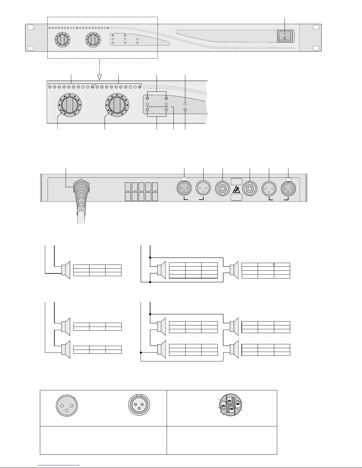
Kontaktbelegung der benötigten Anschlußstecker/ Configuration of the required plugs
+
-
+
-
+
-
Speakon
1
- / 2- 1+ / 2+
+
-
+
-
+
-
+
-
+
-
+
-
Speakon
1
- / 2- 1+ / 2+
Speakon
1
- / 2- 1+ / 2+
Speakon
1
- / 2- 1+ / 2+
DIGAM-3000 DIGAM-5000 DIGAM-7000
4 Ω, 820 W
4 Ω, 1360 W 4 Ω, 1910 W
8 Ω, 450W 8 Ω, 750W 8 Ω, 1050 W
DIGAM-3000 DIGAM-5000 DIGAM-7000
4 Ω, 750W 4 Ω, 1250 W 4 Ω, 1750 W
8 Ω, 410W 8 Ω, 680 W 8 Ω, 955 W
16 Ω, 225W 16 Ω, 375 W 16 Ω, 525 W
DIGAM-3000 DIGAM-5000 DIGAM-7000
4 Ω, 750W 4 Ω, 1250 W 4 Ω, 1750 W
8 Ω, 410W 8 Ω, 680 W 8 Ω, 955 W
16 Ω, 225W 16 Ω, 375 W 16 Ω, 525 W
DIGAM-3000 DIGAM-5000 DIGAM-7000
4 Ω, 205 W
4 Ω, 340W 4 Ω, 477,5 W
8 Ω, 112,5W 8 Ω, 187,5W 8 Ω, 262,5 W
DIGAM-3000 DIGAM-5000 DIGAM-7000
4 Ω, 225W 4 Ω, 375 W 4 Ω, 525 W
DIGAM-3000 DIGAM-5000 DIGAM-7000
4 Ω, 225W 4 Ω, 375 W 4 Ω, 525 W
DIGAM-3000 DIGAM-5000 DIGAM-7000
4 Ω, 205 W 4 Ω, 340 W 4 Ω, 477,5W
8 Ω, 112,5W 8 Ω, 187,5W 8 Ω, 262,5 W
DIGAM-3000 DIGAM-5000 DIGAM-7000
4 Ω, 205 W 4 Ω, 340 W 4 Ω, 477,5W
8 Ω, 112,5W 8 Ω, 187,5W 8 Ω, 262,5 W
DIGAM-3000 DIGAM-5000 DIGAM-7000
4 Ω, 205 W 4 Ω, 340 W 4 Ω, 477,5W
8 Ω, 112,5W 8 Ω, 187,5W 8 Ω, 262,5 W
➃
➅
➄
➆
➇
Page 4

Bitte nehmen Sie die Seite 4 heraus. Sie sehen
dann immer die beschriebenen Bedienelemente
und Anschlüsse.
1 Übersicht der Bedienelemente und
Anschlüsse
1.1 Frontseite (Abb. 1 und 2)
1 Ein-/Ausschalter
2 VU-Meter für den Ausgangspegel des Kanals 1
3 VU-Meter für den Ausgangspegel des Kanals 2
4 Anzeigen „PROTECT“ für Kanal 1 und 2
Die LEDs leuchten bei Überlastung des Verstärkers bzw. bei Kurzschlüssen an den Verstärkerausgängen (14) oder (15).
5 Überhitzungsanzeige „TEMP“
-
blinkt: bei Überhitzung des Verstärkers
-
leuchtet: bei Abschaltung der Stromversor-
gung für die beiden Kanäle A und B
aufgrund zu starker Überhitzung
6 Regler für den Ausgangspegel des Kanals 1
7 Regler für den Ausgangspegel des Kanals 2
8 Eingangsanzeigen „SIGNAL“ für Kanal 1 und 2
Die LEDs leuchten, wenn am jeweiligen Kanaleingang (12) oder (17) ein Signal anliegt.
9 Anzeigen „HI-FREQ“ für Kanal 1 und 2
Die LEDs leuchten bei unerwünschten HF-Einstreuungen für den jeweiligen Kanal.
10 Betriebsanzeige „READY“
1.2 Rückseite (Abb. 2)
11 Netzkabel mit Schukostecker (bei Modell DIGAM-
3000) bzw. 3poligem CEE-Stecker (bei den Modellen DIGAM-5000 und DIGAM-7000) zum Anschluß an 230V~/50Hz
12 symmetrischer Eingang (XLR-Buchse) für den
Kanal 2
13 XLR-Einbaustecker [parallelgeschaltet mit XLR-
Eingangsbuchse (12)] zum Durchschleifen des
Eingangssignals an Kanal 2:
Anschluß an den Eingang eines nachfolgenden
Gerätes (z.B. zweiter Verstärker)
14 Speakon-Ausgangsbuchse zum Anschluß des
Lautsprechers an Kanal 2
Pin 1+ und Pin 2+ = Lautsprecher +
Pin 1
-
und Pin 2-= Lautsprecher
-
15 Speakon-Ausgangsbuchse zum Anschluß des
Lautsprechers an Kanal 1
Pin 1+ und Pin 2+ = Lautsprecher +
Pin 1
-
und Pin 2-= Lautsprecher
-
16 XLR-Einbaustecker [parallelgeschaltet mit XLR-
Eingangsbuchse (17)] zum Durchschleifen des
Eingangssignals an Kanal 1:
Anschluß an den Eingang eines nachfolgenden
Gerätes (z.B. zweiter Verstärker)
17 symmetrischer Eingang (XLR-Buchse) für den
Kanal 1
2 Hinweise für den sicheren Gebrauch
Dieses Gerät entspricht der Richtlinie für elektromagnetische Verträglichkeit 89/336/EWG und der
Niederspannungsrichtlinie 73/23/EWG.
Das Gerät wird mit lebensgefährlicher Netzspannung (230 V~) versorgt. Nehmen Sie darum nie
selbst Eingriffe im Gerät vor. Durch unsachgemäßes Vorgehen besteht die Gefahr eines elektrischen Schlages. Außerdem erlischt beim Öffnen
des Gerätes jeglicher Garantieanspruch.
Beachten Sie für den Betrieb auch unbedingt die folgenden Punkte:
●
Das Gerät ist nur zur Verwendung in Räumen geeignet. Schützen Sie es vor Feuchtigkeit und Hitze
(zulässiger Einsatztemperaturbereich 0–40 °C).
●
Die in dem Gerät entstehende Wärme muß durch
Luftzirkulation abgegeben werden. Decken Sie darum die Lüftungsöffnungen auf der Geräterückseite nicht mit irgendwelchen Gegenständen ab.
●
Stecken Sie nichts durch die Lüftungsöffnungen!
Dies kann zu einem elektrischen Schlag führen.
●
ACHTUNG! Der Verstärker hat eine sehr hohe
Stromaufnahme. Schließen Sie ihn darum nur an
einen extra abgesicherten Stromkreis an. Der
Stromwert der Sicherung muß
-
je nach Modell
16A (DIGAM-3000), 25 A (DIGAM-5000) oder 35A
(DIGAM-7000) betragen. Der Anschluß an das
230-V-Netz muß entsprechend den VDE-Vorschriften bzw. den landesbezogenen Sicherheitsvorschriften durchgeführt werden.
●
Schalten Sie den Verstärker immer aus, bevor Sie
Geräte an den Verstärker anschließen bzw. bestehende Anschlüsse am Verstärker verändern.
●
Nehmen Sie das Gerät nicht in Betrieb, und ziehen
Sie sofort den Netzstecker, wenn:
1. sichtbare Schäden am Gerät, an den Lautspre-
cherleitungen oder an der Netzanschlußleitung
vorhanden sind,
2. nach einem Sturz oder ähnlichem der Verdacht
auf einen Defekt besteht,
3. Funktionsstörungen auftreten.
Lassen Sie das Gerät in jedem Fall in einer Fachwerkstatt reparieren.
●
Eine beschädigte Netzanschlußleitung darf nur
durch den Hersteller oder eine autorisierte Fachwerkstatt ersetzt werden.
●
Ziehen Sie den Netzstecker nie an der Zuleitung
aus der Steckdose.
●
Wird das Gerät zweckentfremdet, nicht richtig angeschlossen, falsch bedient oder nicht fachgerecht
repariert, kann für eventuelle Schäden keine Haftung übernommen werden.
●
Verwenden Sie für die Reinigung nur ein trockenes,
weiches Tuch, niemals Chemikalien oder W asser.
●
Soll das Gerät endgültig aus dem Betrieb genommen werden, übergeben Sie es zur Entsorgung
einem örtlichen Recyclingbetrieb.
3 Einsatzmöglichkeiten
Die Modelle DIGAM-3000, DIGAM-5000 und DIGAM7000 sind Digital-Hochleistungsverstärker für den
Stereo- oder 2-Kanal-Betrieb. Sie sind für den Ein-
D A CH
5
Please take out page 4. Then you can always
see the operating elements and connections described.
1 Operating Elements and Connections
1.1 Front panel (fig. 1 and 2)
1 Power switch
2 VU meter for the output level of channel 1
3 VU meter for the output level of channel 2
4 Indications “PROTECT” for channels 1 and 2
The LEDs light in case of overloading the amplifier resp. in case of short-circuits at the amplifier
outputs (14) or (15).
5 Overheating indication “TEMP”
-
blinks: in case of overheating the amplifier
-
lights: in case the power supply for the two
channels A and B is switched off because the overheating is too much
6 Control for the output level of channel 1
7 Control for the output level of channel 2
8 Input indications “SIGNAL” for channels 1 and 2
The LEDs light if a signal is present at the respective channel input (12) or (17).
9 Indications “HI-FREQ” for channels 1 and 2
The LEDs light in case of unwanted RF interferences for the respective channel.
10 Operating indication “READY”
1.2 Rear panel (fig. 3)
11 Mains cable with plug provided with earthing con-
tact (Schuko) (for model DIGAM-3000) resp. 3-pole
CEE plug (for models DIGAM 5000 and DIGAM-
7000) for connection to 230V~/50Hz
12 Balanced input (XLR jack) for channel 2
13 XLR chassis mount plug [connected in parallel
with XLR input jack (12)] for feeding through the
input signal at channel 2: connection to the input
of a following unit (e.g. a second amplifier)
14 Speakon output jack to connect the speaker to
channel 2
pin 1+ and pin 2+ = speaker +
pin 1
-
and pin 2-= speaker
-
15 Speakon output jack to connect the speaker to
channel 1
pin 1+ and pin 2+ = speaker +
pin 1
-
and pin 2-= speaker
-
16 XLR chassis mount plug [connected in parallel
with XLR input jack (17)] for feeding through the
input signal at channel 1: connection to the input
of a following unit (e.g. a second amplifier)
17 Balanced input (XLR jack) for channel 1
2 Safety Notes
This unit corresponds to the directive for electromagnetic compatibility 89/336 /EEC and the low voltage
directive 73/23/EEC.
This unit uses lethal mains voltage (230 V~). In
order to prevent a shock hazard do not open the
cabinet. Leave servicing to authorized, skilled personnel only. Furthermore, any guarantee claim expires if the unit has been opened.
For operation also observe in any case the following
items:
●
The unit is only suitable for indoor use. Protect it
against humidity and heat (admissible ambient
temperature range 0–40 °C).
●
The heat generated in the unit has to be dissipated
by air circulation. Therefore, the air vents at the
rear side of the unit must not be covered.
●
Do not insert anything into the air vents! This could
result in an electric shock.
●
ATTENTION! The amplifer has a very high current
consumption. Therefore, only connect it to an extra
fused current circuit. The current value of the fuse
depends on the model and must be 16A (DIGAM-
3000), 25A (DIGAM-5000), or 35 A (DIGAM-7000).
The connection to the 230V~ mains must be carried
out according to the VDE regulations resp. to the
safety regulations of the respective country.
●
Always switch off the amplifier prior to connecting
units to the amplifer resp. changing existing connections at the amplifier.
●
Do not set the unit into operation and immediately
take the mains plug out of the mains socket if:
1. damage at the unit, at the speaker cables or at
the mains cable can be seen.
2. a defect might have occurred after a drop or
similar accident.
3. there are malfunctions.
The unit must in any case be repaired by author-
ized, skilled personnel.
●
A damaged mains cable must only be replaced by
the manufacturer or authorized, skilled personnel.
●
Never pull the mains plug out of the mains socket
by means of the mains cable.
●
If the unit is used for purposes other than originally
intended, if it is not connected properly, if it is operated in the wrong way or not repaired by authorized, skilled personnel, there is no liability for possible damage.
●
Only use a dry, soft cloth for cleaning, by no means
chemicals or water.
●
If the unit is to be put out of operation definitively,
bring it to a local recycling plant for disposal.
●
Important for U.K. Customers!
The wires in this mains lead are coloured in accordance with the following code:
green/yellow = earth
blue = neutral
brown = live
As the colours of the wires in the mains lead of this
appliance may not correspond with the coloured
markings identifying the terminals in your plug, proceed as follows:
1. The wire which is coloured green and yellow
must be connected to the terminal in the plug
which is marked with the letter E or by the earth
GB
Page 5

satz auf der Bühne und für allgemeine Beschallungen geeignet.
Die Verstärker zeichnen sich durch hohe SinusAusgangsleistungen und einen großen Wirkungsgrad (95%) aus. Die stabilisierte Digital-Endstufe
des Verstärkers sorgt für eine stabile Ausgangsleistung des Geräts
-
auch bei Schwankungen im
Stromnetz. Umfangreiche Schutzschaltungen schützen den Verstärker und die angeschlossenen Lautsprecher vor Beschädigungen.
4 Verstärker aufstellen
Der Verstärker ist speziell für den Einschub in ein Rack
(482mm/19") ausgelegt. Er kann aber auch als freistehendes Tischgerät verwendet werden. In jedem Fall
muß Luft ungehindert durch die Lüftungsöffnungen auf
der Geräterückseite strömen können, damit eine ausreichende Kühlung gewährleistet ist.
4.1 Rackeinbau
Für die Rackmontage wird 1 HE (1 Höheneinheit =
44,45mm) benötigt. Dabei sollte jedoch ober- und unterhalb des Verstärkers zusätzlich Platz frei bleiben,
damit eine ausreichende Belüftung sichergestellt ist.
Damit das Rack nicht kopflastig wird, sollte der
Verstärker im unteren Bereich des Racks eingeschoben werden. Für eine sichere Befestigung im Rack
reicht die Frontplatte allein nicht aus. Das Gerät muß
über die beiden Montagewinkel auf der Geräterückseite fest mit dem Rack verschraubt werden bzw.
falls das verwendete Rack diese Möglichkeit nicht
bietet
-
zusätzlich durch Seitenschienen oder eine
Bodenplatte gestützt werden.
5 Verstärker anschließen
Vor dem Anschließen von Geräten an den Verstärker
bzw. vor dem Ändern bestehender Anschlüsse den
Verstärker ausschalten.
5.1 Eingänge und Durchschleifausgänge
1) Den Ausgang des Vorverstärkers bzw. des Misch-
pultes an die XLR-Eingangsbuchsen (17) und (12)
der Kanäle 1 und 2 anschließen. Das Eingangssignal des Verstärkers sollte Line-Pegel aufweisen.
2) Die XLR-Stecker (16) und (13) für die Kanäle 1 und
2 sind mit den jeweiligen Eingangsbuchsen (17)
und (12) parallelgeschaltet. An diesen Anschlüssen steht das durchgeschleifte Eingangssignal des
Kanals zur Verfügung. Soll dieses einem nachfolgenden Gerät (z. B. zweiter Verstärker) zugeführt
werden, den Eingang dieses Gerätes an den entsprechenden XLR-Einbaustecker anschließen.
Die XLR-Anschlüsse des Verstärkers sind symmetrisch ausgeführt, können aber auch asymmetrisch angeschlossen werden. Bei asymmetrischer Verbindung
müssen am anzuschließenden Stecker bzw. an der
anzuschließenden Buchse Pin 1 und 3 verbunden werden. (Siehe auch Abb. 8.)
5.2 Lautsprecher
Die Lautsprecher müssen so stark belastbar sein,
wie die Ausgangsleistung des Verstärkers beträgt
(siehe „Technische Daten“, Seite 7).
Die Anschlußmöglichkeiten für mehrere Lautspre-
cher an einen Kanal sind in den Abb. 5–7 dargestellt.
Beim Zusammenschalten von mehreren Lautsprechern ist besonders auf die richtige Verbindung der
Plus- und Minusanschlüsse zu achten und darauf,
daß die Gesamtimpedanz mindestens 2 Ω beträgt.
1) Die Lautsprecher an die Speakon-Buchsen (15)
und (14) der Kanäle 1 und 2 anschließen.
Kontaktbelegung am Stecker (siehe Abb. 8):
Pins 1+ und 2+ an den Lautsprecher-Pluspol
(gekennzeichnete Ader)
Pins 1
-
und 2-an den Lautsprecher-Minuspol
2) Die Speakon-Stecker in die entsprechenden Buchsen stecken und nach rechts drehen, bis sie einrasten. Zum späteren Herausziehen den Sicherungsriegel am Stecker nach hinten schieben, und
den Stecker nach links drehen.
5.3 Netzanschluß
Zum Schluß den Verstärker an das Netz (230 V~ /
50Hz) anschließen:
-
Bei Modell DIGAM-3000 den Schukostecker der
Netzanschlußleitung (11) mit einer Schukosteckdose verbinden.
-
Bei den Modellen DIGAM-5000 und DIGAM-7000
den CEE-Stecker der Netzanschlußleitung (11)
an eine 3pol. CEE-Steckdose anschließen.
Achtung! Der Verstärker hat eine sehr hohe Stromaufnahme. Schließen Sie ihn darum nur an einen extra abgesicherten Stromkreis an. Der Stromwert der
Sicherung muß
-
je nach Modell -16A (DIGAM-
3000), 25A (DIGAM-5000) oder 35 A (DIGAM-7000)
betragen.
6 Bedienung
Vor dem ersten Einschalten die Regler (6) und (7)
ganz nach links auf „
-
30dB“ stellen.
Zur Vermeidung von lauten Schaltgeräuschen
den Endverstärker in einem PA-System immer nach
allen anderen Geräten einschalten und ihn nach dem
Betrieb als erstes Gerät wieder ausschalten.
6.1 Einschalten
Den Verstärker mit dem Ein-/Ausschalter (1) einschalten. Zur Anzeige der Betriebsbereitschaft leuchtet nach ca. 4 Sekunden die grüne LED „READY“
(10). Wenn an den Eingängen (17) und (12) der
Kanäle 1 und 2 eine Signalspannung anliegt, leuchten die grünen LEDs „SIGNAL“ (8) der beiden Kanäle.
6.2 Pegel einstellen
Mit dem Regler (6) den Ausgangspegel des Kanals 1
einstellen und mit dem Regler (7) den Ausgangspegel des Kanals 2.
Die Regler nur so weit wie notwendig aufdrehen,
bis die maximal gewünschte Lautstärke erreicht ist.
Als Aussteuerungsanzeige dient für Kanal 1 das VUMeter (2) und für Kanal 2 das VU-Meter (3). Die roten
LEDs der VU-Meter zeigen Übersteuerungen des Verstärkers an. Bei Übersteuerungen die Pegelregler
entsprechend zurückdrehen.
6
symbol , or coloured green or green and yel-
low.
2. The wire which is coloured blue must be connected to the terminal which is marked with the
letter N or coloured black.
3. The wire which is coloured brown must be connected to the terminal which is marked with the
letter L or coloured red.
Warning
-
This appliance must be earthed.
3 Applications
Models DIGAM-3000, DIGAM-5000, and DIGAM7000 are digital high power amplifiers for stereo or
2-channel operation. They are suitable for stage and
general PAapplications.
The amplifiers feature high rms output power and
high efficiency (95%). The stabilized digital power
amplifying part of the amplifier provides a stable output power of the unit
-
even with fluctuations in the
mains. Extensive protection circuits protect the amplifier and the connected speakers against damage.
4 Installation of the Amplifier
The amplifier has especially been designed for insertion into a rack (482 mm/19") but it can also be used
as a table top unit. In each case the air must be able
to circulate without obstruction through the vents at
the rear side of the unit to ensure a sufficient cooling.
4.1 Rack installation
For rack installation 1 rack space (= 44.45mm) is required. There must remain additional space above
and below the amplifier so that a sufficient ventilation
is ensured.
In order to avoid a top load of the amplifier, it
should be inserted in the lower area of the rack. For
safe fixing in the rack the front plate alone is not sufficient. The unit must tightly be screwed with the rack
via both mounting brackets at the rear side of the
unit. If the rack in use does not offer this facility, the
unit must be additionally supported by lateral rails or
a bottom plate.
5 Connection of the Amplifier
Prior to connecting units to the amplifier resp. changing existing connections, switch off the amplifier.
5.1 Inputs and feed-through outputs
1) Connect the output of the preamplifier resp. mixer
to the XLR input jacks (17) and (12) of channels 1
and 2. The input signal of the amplifier should
have line level.
2) The XLR plugs (16) and (13) for channels 1 and 2
are connected in parallel with the respective input
jacks (17) and (12). The fed-through input signal
of the channel is available at these connections. If
it is to be fed to a following unit (e.g. a second amplifier), connect the input of this unit to the corresponding XLR chassis mount plug.
The XLR connections of the amplifier are balanced,
but they can also be connected unbalanced. In this
case connect pins 1 and 3 of the plug resp. jack to be
connected. (See also fig. 8.)
5.2 Speakers
The speakers must have a capability corresponding
to the output power of the amplifier (see “Specifications”, page 7).
The connection possibilities for several speakers
to one channel are shown in figures 5 –7. When
connecting several speakers, it is especially important to pay attention to the correct positive and negative connections and that the total impedance is at
least 2Ω.
1) Connect the speakers to the Speakon jacks (15)
and (14) of channels 1 and 2.
Pin configuration at the plug (see fig. 8):
pins 1+ and 2+ at the positive pole of the speaker
(coded core)
pins 1
-
and 2-at the negative pole of the speaker
2) Connect the Speakon plugs to the corresponding
jacks and turn them to the right until they lock into
place. For removing them later, slide the safety lock
at the plug to the rear, and turn the plug to the left.
5.3 Mains connection
Finally connect the unit to the mains (230V~ /50 Hz):
-
For model DIGAM-3000:
Connect the plug provided with earthing contact
(Schuko) of the mains cable (11) to a socket provided with earthing contact (Schuko).
-
For models DIGAM-5000 and DIGAM-7000:
Connect the CEE plug of the mains cable (11) to a
3-pole CEE socket.
Attention! The amplifier has a very high current consumption. Therefore, only connect it to an extra fused
current circuit. The current value of the fuse depends
on the model and must be 16A (DIGAM-3000), 25 A
(DIGAM-5000), or 35A (DIGAM-7000).
6 Operation
Prior to the first switching on set the controls (6) and
(7) fully counterclockwise to “
-
30dB”.
In order to avoid a strong switching noise always
switch on the power amplifier in a PAsystem after all
other units have been switched on, and after operation switch it off first.
6.1 Switching on
Switch on the amplifier with the power switch (1). The
green LED “READY” (10) lights after approx. 4 seconds to indicate that the unit is ready for operation. If
a signal voltage is present at the inputs (17) and (12)
of channels 1 and 2, the green LEDs “SIGNAL” (8) of
both channels light.
6.2 Adjusting the level
Adjust the output level of channel 1 with the control (6)
and the output level of channel 2 with the control (7).
Only turn up the controls as far as necessary until
the max. desired volume will be reached. The VU
meter (2) serves as output indication for channel 1
and the VU meter (3) for channel 2. The red LEDs of
the VU meters show overdriving of the amplifier. In
case of overdriving turn back the level controls correspondingly.
Page 6
7 Schutzschaltungen
Der Verstärker sowie die angeschlossenen Lautsprecher werden durch umfangreiche Schutzschaltungen
gegen Beschädigungen geschützt.
Einschaltverzögerung der Lautsprecher
Um beim Einschalten des Verstärkers eine Beschädigung der Lautsprecher durch Schaltgeräusche
(Knacken) zu verhindern, werden diese erst ca. 4 Sekunden nach dem Einschalten intern mit den Ausgängen verbunden bzw. beim Ausschalten sofort von
den Ausgängen getrennt.
Kurzschluß- und Überlastschutz
Bei Kurzschlüssen an den Ausgängen und bei zu großer Belastung des Verstärkers wird die KurzschlußSchutzschaltung aktiviert. Zusätzlich leuchtet die LED
„PROTECT“ (4) für den betroffenen Kanal auf.
Bei Aufleuchten einer „PROTECT“-LED den Ver-
stärker ausschalten, und die Fehlerquelle beheben.
Überhitzung
Steigt die Temperatur im Gerät auf bis zu 65 °C an,
begrenzt das Gerät die Ausgangsleistung. Zur Anzeige dieses Vorgangs blinkt die gelbe LED „TEMP“
(5). In diesem Fall muß die Belüftung verbessert
und/ oder der Ausgangspegel durch Zurückdrehen
der Regler (6) und (7) reduziert werden.
Erfolgt dies nicht und steigt die Temperatur trotz
interner Leistungsregulierung auf ca. 75 °C an, wird
die Stromversorgung für beide Kanäle abgeschaltet.
In diesem Fall leuchtet die LED „TEMP“ permanent.
Hat sich das Gerät ausreichend abgekühlt, schaltet
sich die Stromversorgung für die Kanäle wieder ein,
und die LED „TEMP“ erlischt.
Gleichspannungsschutz
Liegt eine Gleichspannung an einem der Verstärkerausgänge an (z.B. durch einen Defekt der Endstufe),
wird die Stromversorgung für beide Kanäle abgeschaltet.
Den Verstärker ausschalten, und die Fehlerquelle
beheben.
ACHTUNG: Reparaturen am Gerät dürfen nur von
qualifiziertem Fachpersonal durchgeführt werden!
Schutz bei Hochfrequenzeinstreuungen
Entsprechende Schutzschaltungen sorgen dafür, daß
starke, andauernde Hochfrequenzsignale, die zu einer Beschädigung der Lautsprecher führen können,
nicht an die Verstärkerausgänge gelangen.
Starke Hochfrequenzeinstreuungen werden durch
Blinken der gelben LED “HI-FREQ” (9) des jeweiligen
Kanals angezeigt.
Den Verstärker ausschalten, und die Ursache der
Hochfrequenzeinstreuungen beseitigen.
7
7 Protection Circuits
The amplifier as well as the connected speakers are
protected against damage by extensive protection
circuits.
Switch-on delay of the speakers
In order to avoid damage to the speakers by switching
noise (cracking) when switching on the amplifier, the
speakers are only connected internally with the outputs
after approx. 4 seconds resp. they are immediately disconnected from the outputs when switching off.
Short circuit and overload protection
In case of short circuits at the outputs and in case the
amplifier is too much overloaded, the short-circuit
protection circuit is activated. In addition the LED
“PROTECT” (4) lights for the concerned channel.
If a “PROTECT” LED lights up, switch off the am-
plifier and eliminate the source of error.
Overheating
If the temperature inside the unit rises up to 65 °C,
the unit limits the output power. The yellow LED
“TEMP” (5) blinks to indicate this procedure. In this
case the ventilation must be improved and/ or the
output level must be reduced by turning back the
controls (6) and (7).
If this is not carried out and the temperature rises
to approx. 75°C in spite of internal power regulation,
the power supply for both channels is switched off. In
this case the LED “TEMP” lights continuously. If the
unit has sufficiently cooled down, the power supply
for the channels switches on again and the LED
“TEMP” expires.
DC voltage protection
If a DC voltage is present at one of the amplifier outputs (e. g. by a defect of the power amplifier), the
power supply for both channels is switched off.
Switch off the amplifier and eliminate the source
of error.
ATTENTION: Repairs at the unit must only be carried
out by qualified, skilled personnel!
Protection in case of RF interference
Corresponding protection circuits ensure that strong,
permanent RF signals which may damage the
speakers do not reach the amplifier outputs.
Strong RF interference is indicated by blinking of
the yellow LED “HI-FREQ” (9) of the respective
channel.
Switch off the amplifier and eliminate the reason for
the RF interference.
Modell DIGAM-3000 DIGAM-5000 DIGAM-7000
Ausgangsleistung
(Sinusleistung = Musikleistung)
Stereo 2Ω/Klirrfaktor
Stereo 4Ω/Klirrfaktor
Stereo 8Ω/Klirrfaktor
Leistungsfaktor (cos ϕ)
2 x 1500W/1 %
2 x 820W/0,5 %
2 x 450W/0,5 %
> 0,95
(bei 200
-
3500W)
2 x 2500W/1 %
2 x 1360W/0,5 %
2 x 750W/0,5 %
> 0,95
(bei 200
-
5000W)
2 x 3500W/1 %
2 x 1910W/0,5 %
2 x 1050W/0,5 %
> 0,95
(bei 200
-
6000W)
Frequenzbereich
Dämpfungsfaktor/8 Ω
Anstiegsgeschwindigkeit (slew rate)/8 Ω
Störabstand
10-40000 Hz
400 (100Hz/10 kHz)
50V/µs
100dB
10-40000 Hz
400 (100Hz/10 kHz)
50V/µs
100dB
10-40000 Hz
400 (100Hz/10 kHz)
50V/µs
100dB
Abmessungen (B x H x T)
Höheneinheiten
Gewicht
482 x 44 x 487mm
1HE
9,5kg
482 x 44 x 487mm
1HE
10,4kg
482 x 44 x 487mm
1HE
10,4kg
Min. Lautsprecherimpedanz
Eingangspegel
Eingangsimpedanz
2Ω
0,775V
10kΩ
2Ω
0,775V
10kΩ
2Ω
0,775V
10kΩ
Zulässige Einsatztemperatur
Betriebsspannung
Netzanschluß
Stromverbrauch
0–40°C
230V~/50 Hz/3700 VA
über Schukostecker
max. 16A
0–40°C
230V~/50 Hz/5800 VA
über 3pol. CEE-Stecker
max. 25A
0–40°C
230V~/50 Hz/7400 VA
über 3pol. CEE-Stecker
max. 32A
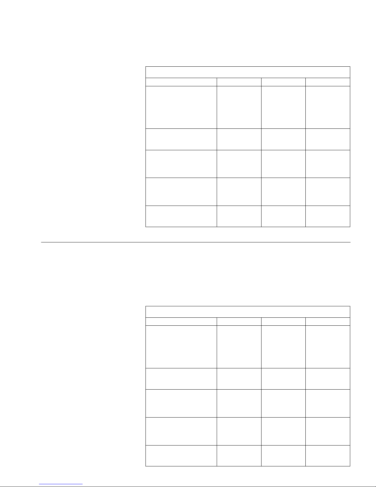
Technische Daten
Model DIGAM-3000 DIGAM-5000 DIGAM-7000
Output power
(rms power = music power)
stereo 2Ω/THD
stereo 4Ω/THD
stereo 8Ω/THD
Power factor (cos ϕ)
2 x 1500W/1 %
2 x 820W/0.5 %
2 x 450W/0.5 %
> 0.95
(at 200
-
3500W)
2 x 2500W/1 %
2 x 1360W/0.5 %
2 x 750W/0.5 %
> 0.95
(at 200
-
5000W)
2 x 3500W/1 %
2 x 1910W/0.5 %
2 x 1050W/0.5 %
> 0.95
(at 200
-
6000W)
Specifications
Frequency range
Damping factor/8 Ω
Slew rate/8 Ω
S/N ratio
10
-
40000 Hz
400 (100Hz/10 kHz)
50V/µs
100dB
10
-
40000 Hz
400 (100Hz/10 kHz)
50V/µs
100dB
10
-
40000 Hz
400 (100Hz/10 kHz)
50V/µs
100dB
Dimensions (W x H x D)
Rack spaces
Weight
482 x 44 x 487mm
1rack space
9.5kg
482 x 44 x 487mm
1rack space
10.4kg
482 x 44 x 487mm
1rack space
10.4kg
Min. speaker impedance
Input level
Input impedance
2Ω
0.775V
10kΩ
2Ω
0.775V
10kΩ
2Ω
0.775V
10kΩ
Admissible ambient temperature
Operating voltage
Mains connection
Power consumption
0–40°C
230V~/50 Hz/3700 VA
via Schuko plug
max. 16A
0–40°C
230V~/50 Hz/5800 VA
via 3-pole CEE plug
max. 25A
0–40°C
230V~/50 Hz/7400 VA
via 3-pole CEE plug
max. 32A
Laut Angaben des Herstellers. Änderungen vorbehalten.
According to the manufacturer. Subject to change
.
Page 7

Enlevez la page 4 de manière à visualiser les éléments et branchements.
1 Eléments et branchements
1.1 Face avant (schéma 1 et 2)
1 Interrupteur Marche/Arrêt
2 VU-mètre pour le niveau de sortie du canal 1
3 VU-mètre pour le niveau de sortie du canal 2
4 Diodes “PROTECT” pour les canaux 1 et 2
Les diodes brillent en cas de surcharge de l’amplificateur ou de court-circuits sur les sorties (14)
ou (15) de l’amplificateur.
5 Diode “TEMP”: surchauffe
-
clignote: surchauffe de l’amplificateur
-
brille en continu: si l’alimentation pour les deux
canaux A et B est coupée à
cause d’une surchauffe importante
6 Potentiomètre de réglage du niveau de sortie du
canal 1
7 Potentiomètre de réglage du niveau de sortie du
canal 2
8 Diodes d’entrée “SIGNAL” pour les canaux 1 et 2;
brillent lorsque un signal est présent à l’entrée du
canal (12) ou (17)
9 Diodes “HI-FREQ” pour les canaux 1 et 2; brillent
en cas d’interférences HF non désirées sur un
canal
10 Diode témoin de fonctionnement “READY”
1.2 Face arrière (schéma 3)
11 Cordon secteur (branchement secteur 230V~/
50Hz) avec fiche Schuko (DIGAM 3000) ou fiche
CEE 3 pôles (DIGAM-5000 et DIGAM-7000)
12 Entrée symétrique (prise femelle XLR) pour le
canal 2
Vi preghiamo di aprire completamente la pagina 3.
Così vedrete sempre gli elementi di comando e i
collegamenti descritti.
1 Elementi di comando e collegamenti
1.1 Pannello frontale (fig. 1 e 2)
1 Interruttore on/off
2 VU-metro per il livello d’uscita del canale 1
3 VU-metro per il livello d’uscita del canale 2
4 Spie “PROTECT” per i canali 1 e 2
I led si accendono in caso di sovraccarico dell’amplificatore o in caso di cortocircuiti alle uscite (14)
o (15).
5 Spia di surriscaldamento “TEMP”
-
lampeggia:
in caso di surriscaldamento dell’amplificatore
-
rimane accesa:
durante il disinserimento dell’alimentazione per
i due canali A e B in seguito a riscaldamento
eccessivo
6 Regolatore per il livello d’uscita del canale 1
7 Regolatore per il livello d’uscita del canale 2
8 Spie d’ingresso “SIGNAL” per i canali 1 e 2
i led rimangono accesi se al relativo ingresso (12)
o (17) è presente un segnale
9 Spie “HI-FREQ” per i canali 1 e 2
i led rimangono accesi nel caso di interferenze
HF indesiderate nel relativo canale
10 Spia di funzionamento “READY”
1.2 Pannello posteriore (fig. 3)
11 Cavo rete con spina tedesca (modello DIGAM-
3000) oppure spina CEE a 3 poli (modelli DIGAM5000 e DIGAM-7000) per la rete 230V~/50Hz
12 Ingresso simmetrico (presa XLR) per il canale 2
13 Prise mâle XLR [branchée en parallèle avec l’en-
trée XLR (12)]: pour faire passer le signal d’entrée sur le canal 2:
branchement à l’entrée d’un autre appareil (par
exemple deuxième amplificateur)
14 Prise de sortie Speakon pour brancher un haut-
parleur au canal 2
pin 1+ et pin 2+ = + HP
pin 1
-
et pin 2-= -HP
15 Prise de sortie Speakon pour brancher un haut-
parleur au canal 1
pin 1+ et pin 2+ = + HP
pin 1
-
et pin 2-= -HP
16 Prise mâle XLR [branchée en parallèle avec l’en-
trée XLR (17)]: pour faire passer le signal d’entrée sur le canal 1:
branchement à l’entrée d’un autre appareil (par
exemple deuxième amplificateur)
17 Entrée symétrique (prise femelle XLR) pour le
canal 1
2 Conseils de sécurité
Cet amplificateur répond à la norme européenne
89/ 336/CEE relative à la compatibilité électromagnétique et à la norme 73/ 23 /CEE portant sur les
appareils à basse tension.
L’appareil est alimenté par une tension dangereuse en 230V~. Ne touchez jamais l’intérieur de l’appareil car, en cas de mauvaise manipulation, vous
pourriez subir une décharge électrique mortelle.
Faites plutôt appel à un spécialiste. En outre, l’ouverture de l’appareil rend tout droit à la garantie
caduque.
Respectez scrupuleusement les points suivants:
●
Cet appareil n’est conçu que pour une utilisation
en intérieur. Protégez-le de l’humidité et de la chaleur (température ambiante autorisée 0–40 °C).
●
La chaleur dégagée par l’amplificateur doit être
correctement évacuée. Les ouïes de ventilation
sur la face arrière de l’appareil ne doivent en aucun
cas être obturées.
13 Connettore ad incasso XLR [in parallelo con la
presa d’ingresso (12)] per far passare il segnale
d’ingresso attraverso il canale 2:
collegamento all’ingresso di un apparecchio a
valle (p.es. di un secondo amplificatore)
14 Presa d’uscita Speakon per il collegamento
dell’altoparlante al canale 2
pin 1+ e pin 2+ = altoparlante +
pin 1
-
e pin 2-= altoparlante
-
15 Presa d’uscita Speakon per il collegamento
dell’altoparlante al canale 1
pin 1+ e pin 2+ = altoparlante +
pin 1
-
e pin 2-= altoparlante
-
16 Connettore ad incasso XLR [in parallelo con la
presa d’ingresso (17)] per far passare il segnale
d’ingresso attraverso il canale 1:
collegamento all’ingresso di un apparecchio a
valle (p.es. di un secondo amplificatore)
17 Ingresso simmetrico (presa XLR) per il canale 1
2 Avvisi di sicurezza
Quest’apparecchio corrisponde alle direttive CE
89/ 336/ CEE sulla compatibilità elettromagnetica e
73/23/CEE per apparecchi a bassa tensione.
Quest’apparecchio funziona con tensione di rete di
230V~. Non intervenire mai al suo interno; la manipolazione scorretta può provocare delle scariche
pericolose. Se l’apparecchio viene aperto, cessa
ogni diritto di garanzia.
Durante l’uso si devono osservare assolutamente i
seguenti punti:
●
L’apparecchio è previsto solo per l’uso all’interno di
locali. Proteggerlo dall’umidità e dal calore (temperatura d’impiego ammessa fra 0°C e 40 °C).
●
Dev’essere garantita la libera circolazione dell’aria
per dissipare il calore che viene prodotto all’interno
dell’apparecchio. Non coprire in nessun modo le
fessure di aerazione sul retro.
●
Non inserire oggetti nelle fessure di aerazione. Altrimenti si potrebbe provocare una scarica elettrica.
●
N’introduisez rien dans les ouïes de ventilation,
vous pourriez vous électrocuter.
●
ATTENTION! La consommation de cet amplificateur est très importante. Reliez-le à un circuit avec
fusible. La valeur du fusible dépend du modèle:
elle doit être:
DIGAM-3000: 16 A
DIGAM-5000: 25 A
DIGAM-7000: 35 A
La connexion de l’amplificateur au secteur 230V~
doit être effectuée conformément aux normes édictées par le VDE ou par l’office national de sécurité.
●
Coupez toujours l’alimentation de l’amplificateur
avant de relier d’autres appareils ou de modifier les
branchements.
●
Ne faites pas fonctionner l’appareil et débranchezle immédiatement lorsque:
1. l’appareil, les câbles haut-parleurs ou le cordon
secteur présentent des dommages.
2. après une chute ou un cas similaire, vous avez
un doute sur l’état de l’appareil.
3. des dysfonctionnements apparaissent.
Faites appel à un technicien spécialisé pour effectuer les réparations.
●
Seul le fabricant ou un technicien habilité peuvent
remplacer le cordon secteur endommagé.
●
Ne débranchez jamais l’appareil en tirant sur le
cordon secteur.
●
Nous déclinons toute responsabilité en cas de
dommage si l’appareil est utilisé dans un but autre
que celui pour lequel il a été conçu, s’il n’est pas
correctement branché, utilisé ou réparé.
●
Pour le nettoyer, utilisez seulement un chiffon sec
et souple, jamais de produits chimiques ou d’eau.
●
Lorsque l’appareil est définitivement retiré du circuit de distribution, vous devez le déposer dans
une usine de recyclage adaptée.
3 Possibilités d’utilisation
Les amplificateurs DIGAM-3000, DIGAM-5000 et
DIGAM-7000 sont des amplificateurs de puissance
●
ATTENZIONE!L’amplificatore presenta un alto assorbimento di corrente. Pertanto occorre collegarlo
solo con un circuito appositamente protetto. Il valore del fusibile deve essere
-
in funzione del mo-
dello
-
16A (DIGAM-3000), 25 A (DIGAM-5000) o
35 A (DIGAM-7000). Il collegamento con la rete
230V~ deve essere conforme alle norme VDE e/o
alle norme di sicurezza nazionali.
●
Spegnere l’apparecchio prima di effettuare dei collegamenti o di modificare i collegamenti esistenti.
●
Non mettere in funzione l’apparecchio e staccare
subito la spina rete se:
1. l’apparecchio, i cavi degli altoparlanti o il cavo
rete presentano dei danni visibili;
2. dopo una caduta o dopo eventi simili sussiste il
sospetto di un difetto;
3. l’apparecchio non funziona correttamente.
Per la riparazione rivolgersi sempre ad una officina
competente.
●
Il cavo rete, se danneggiato, deve essere sostituito
solo dal costruttore o da un laboratorio autorizzato.
●
Staccare il cavo rete afferrando la spina, senza tirare il cavo.
●
Nel caso di uso improprio, di collegamenti sbagliati,
di impiego scorretto o di riparazione scorretta non si
assume nessuna responsabilità per eventuali danni.
●
Per la pulizia usare solo un panno asciutto e morbido; non impiegare in nessun caso prodotti chimici o acqua.
●
Se si desidera eliminare l’apparecchio definitivamente, consegnarlo per lo smaltimento ad un’istituzione locale per il riciclaggio.
3 Possibilità d’impiego
I modelli DIGAM-3000, DIGAM-5000 e DIGAM-7000
sono amplificatori digitali di potenza PAper il funzionamento stereo o a 2 canali. Sono adatti per usi professionali e sonorizzazioni generali.
Gli amplificatori si distinguono per alta potenza efficace e per alto rendimento (95%). Lo stadio finale
digitale stabilizzato dell’amplificatore garantisce una
potenza d’uscita stabile, anche alla presenza di oscil-
8
I
F B CH
Page 8

digitaux pour un fonctionnement en mode stéréo ou
2 canaux et peuvent être utilisés sur scène ou pour
tout autre type de sonorisation.
Ils se caractérisent par de grandes puissances de
sortie RMS et un rendement élevé (95 %). L’étage
final digital stabilisé garantit une puissance de sortie
stable même en cas de fluctuations du courant. De
nombreux circuits de protection sont prévus pour
protéger l’amplificateur et les haut-parleurs reliés.
4 Installation
L’amplificateur est conçu pour une installation en
rack (482 mm /19"). Il peut également être posé directement sur une table; dans tous les cas, veillez à
assurer une circulation d’air correcte pour garantir un
refroidissement suffisant de l’appareil.
4.1 Installation en rack
Pour un montage en rack, 1 unité (= 44,45mm) est
nécessaire; veillez cependant à laisser suffisamment
de place au-dessus et sous l’amplificateur pour garantir une circulation d’air correcte.
L’amplificateur doit être placé dans la partie inférieure du rack pour éviter une surcharge sur la partie supérieure du rack. Pour une fixation sûre, la plaque avant en suffit pas: l’appareil doit être vissé via
les deux étriers de montage sur la face arrière; si le
rack ne propose pas cette option, utilisez en plus des
rails latéraux ou une plaque de fond.
5 Branchements
Avant d’effectuer ou de modifier tout branchement,
vérifiez que l’appareil est débranché.
5.1 Entrées et sorties de passage
1) Reliez la sortie du préamplificateur ou de la table
de mixage aux prises d’entrée femelles XLR (17)
et (12) des canaux 1 et 2. Le signal d’entrée de
l’amplificateur doit avoir un niveau Ligne.
2) Les prises mâles XLR (16) et (13) pour les canaux
1 et 2 sont branchées en parallèle avec les prises
lazioni nella rete. Appositi circuiti proteggono l’amplificatore e gli altoparlanti collegati.
4 Collocamento dell’amplificatore
L’amplificatore è previsto per il montaggio in un rack
(482mm/19"), ma può essere sistemato anche su un
tavolo. In ogni caso, l’aria deve poter circolare liberamente attraverso le fessure di aerazione sul retro per
garantire un raffreddamento sufficiente degli stadi finali.
4.1 Montaggio in un rack
Per il montaggio in rack è richiesta un’unità di altezza
(= 44,45 mm). Tuttavia, sotto e sopra l’amplificatore
dovrebbe rimanere dello spazio libero per l’aerazione.
Per un migliore equilibrio del rack è opportuno che
l’amplificatore venga montato nella parte bassa del
rack. Il solo pannello frontale non è sufficiente per il
fissaggio. Con le due staffe di montaggio, il retro
dell’apparecchio può essere avvitato bene al rack.
Se il rack non permette questa possibilità occorre impiegare delle guide laterali o un piano su cui poggia
l’amplificatore.
5 Collegamento dell’amplificatore
Prima di collegare degli apparecchi o prima di modificare i collegamenti esistenti spegnere l’amplificatore.
5.1 Ingressi e uscite passanti
1) Collegare l’uscita del preamplificatore o del mixer
con le prese d’ingresso XLR (17) e (12) dei canali
1 e 2. Il segnale d’ingresso dell’amplificatore do-
vrebbe aver un livello Line.
2) I connettori XLR (16) e (13) per i canali 1 e 2 sono
in parallelo con le relative prese d’ingresso (17) e
(12). Il segnale d’ingresso passante del canale è
presente a questi contatti. Se tale segnale deve es-
sere portato ad un apparecchio a valle (per esem-
pio ad un secondo amplificatore), occorre colle-
gare l’ingresso di tale apparecchio con il relativo
connettore XLR.
d’entrée (17) et (12). Le signal d’entrée passé du
canal se trouve à ces prises; si vous souhaitez diriger ce signal vers un autre appareil, par exemple
un deuxième amplificateur, reliez l’entrée de ce
dernier à la prise mâle XLR correspondante.
Les prises XLR de l’amplificateur sont symétriques. Il
est également possible d’effectuer un branchement
asymétrique: pour ce faire, reliez les pins 1 et 3 du
connecteur correspondant. (Voir aussi schéma 8.)
5.2 Haut-parleurs
Les haut-parleurs doivent avoir une puissance admissible suffisante pour supporter la puissance de
sortie de l’amplificateur (reportez-vous au paragraphe des caractéristiques techniques, page 10).
Les schémas 5– 7 représentent les possibilités de
branchement de plusieurs haut-parleurs à un canal: il
convient de bien vérifier les branchements des bornes plus et moins; l’impédance totale doit être de 2Ω
au moins.
1) Reliez les haut-parleurs aux prises Speakon (15) et
(14) des canaux 1 et 2.
Configuration de la fiche Speakon (voir schéma 8):
pin 1+ et pin 2+ au pôle Plus HP
(conducteur repéré)
pin 1
-
et pin 2-au pôle Moins HP
2) Mettez les fiches Speakon dans les prises corres-
pondantes et tournez-les vers la droite jusqu’à ver-
rouillage. Pour retirer la fiche, poussez vers l’ar-
rière la bague de verrouillage et tournez la fiche
vers la gauche.
5.3 Branchement secteur
Pour relier l’amplificateur au secteur 230 V~ / 50 Hz,
procédez comme suit:
-
DIGAM-3000: reliez la fiche Schuko (fiche 2 pôles
avec terre) du cordon secteur (11) à une prise
secteur Schuko.
-
DIGAM-5000 et DIGAM-7000: reliez la fiche CEE
du cordon (11) à une prise CEE 3 pôles.
Attention! La consommation de cet amplificateur est
très importante. Reliez-le à un circuit avec fusible. La
I connettori XLR dell’amplificatore sono simmetrici,
ma supportano anche un collegamento asimmetrico.
In questo caso, nel connettore e/o nella presa da
collegare occorre collegare i pin 1 e 3. (Vedere anche
fig. 8.)
5.2 Altoparlanti
Gli altoparlanti devono supportare una potenza non
inferiore alla potenza d’uscita dell’amplificatore (vedi
“Dati tecnici”, pag. 10).
Le figure 5 – 7 illustrano le possibilità di collegamento di più altoparlanti con un canale. Collegando
più altoparlanti occorre badare ad un corretto collegamento fra i poli positivi e negativi. Inoltre, l'impedenza totale non deve superare 2Ω
1) Collegare gli altoparlanti con le prese Speakon
(15) e (14) dei canali 1 e 2.
Contatti dei connettori (vedi fig. 8):
pin 1+ e 2+ con il positivo dell’altoparlante
(conduttore marcato)
pin 1
-
e 2-con il negativo dell’altoparlante
2) Inserire i connettori Speakon nelle relative prese e
girarli a destra fino allo scatto. Per staccarli suc-
cessivamente, spostare la leva di sicurezza all’in-
dietro e girare il connettore a sinistra.
5.3 Collegamento alla rete
Alla fine collegare l’amplificatore con la rete (230V~ /
50Hz):
-
nel modello DIGAM-3000 inserire la spina tede-
sca del cavo rete (11) in un’apposita presa.
-
nei modelli DIGAM-5000 e DIGAM-7000 inserire
la spina CEE del cavo rete (11) in un presa CEE a
3 poli.
Attenzione! L’amplificatore presenta un alto assorbi-
mento di corrente. Pertanto occorre collegarlo solo
con un circuito appositamente protetto. Il valore dei
fusibili deve essere
-
in funzione del modello -16A
(DIGAM-3000), 25A (DIGAM-5000) o 35A (DIGAM-
7000).
valeur du fusible dépend du modèle: elle doit être
16A (DIGAM-3000), 25A (DIGAM-5000) ou 35 A
(DIGAM-7000).
6 Utilisation
Avant d’allumer l’amplificateur, mettez les potentiomètres (6) et (7) entièrement à gauche sur “
-
30dB”.
Pour éviter tout bruit fort lors de l’allumage, l’amplificateur dans un système PAdoit toujours être allumé après les autres appareils et après l’utilisation
être éteint en premier.
6.1 Marche
Allumez l’amplificateur avec l’interrupteur (1) Marche/Arrêt. La diode verte “READY ” (10), témoin de
fonctionnement, brille après 4 secondes environ. S’il y
a, aux entrées (17) et (12) des canaux 1 et 2 un signal,
les diodes vertes “SIGNAL” (8) des canaux brillent.
6.2 Réglages des niveaux
Réglez le niveau de sortie du canal 1 avec le potentiomètre (6) et le niveau de sortie du canal 2 avec le
potentiomètre (7).
Tournez-les jusqu’à obtention du volume souhaité. Le VU-mètre (2) pour le canal 1 et le VU-mètre (3)
pour le canal 2 servent de témoins. Les diodes rouges indiquent toute surcharge; dans ce cas, tournez
les réglages dans le sens inverse.
7 Circuits de protection
L’amplificateur et les haut-parleurs reliés sont protégés par de nombreux circuits de protection.
Temporisation d’allumage des haut-parleurs
Pour éviter tout dommage sur les haut-parleurs lors
de l’allumage de l’amplificateur, les haut-parleurs ne
sont reliés aux sorties que 4 secondes environ après
la mise sous tension et ils sont déconnectés immédiatement, lors de l’arrêt de l’amplificateur.
6 Funzionamento
Prima della prima accensione girare i regolatori (6) e
(7) tutto a sinistra su “
-
30dB”.
Per evitare forti rumori di commutazione, accendere l’amplificatore negli impianti PA sempre per ultimo e spegnerlo per primo.
6.1 Accensione
Accendere l’amplificatore con l’interruttore on/off (1).
Dopo 4 secondi circa si accende la spia verde di funzionamento “READY” (10). Se agli ingressi (17) e
(12) dei canali 1 e 2 è presente un segnale, i led verdi
“SIGNAL” (8) dei due canali si accendono.
6.2 Regolazione del livello
Con il regolatore (6) si imposta il livello d’uscita del
canale 1, e con il regolatore (7) quello del canale 2.
Aprire i regolatori solo fino al raggiungimento del
volume massimo desiderato. I livelli vengono visualizzati dai VU-metro (2) per il canale 1 e (3) per il canale 2. Il sovrapilotaggio viene indicato dai led rossi.
In questo caso occorre abbassare il livello.
7 Circuiti di protezione
L’amplificatore e gli altoparlanti collegati sono protetti
da numerosi circuiti di protezione.
Accensione ritardata degli altoparlanti
Per evitare danni agli altoparlanti per rumori di commutazione durante l’accensione dell’amplificatore, gli
altoparlanti vengono collegati con le uscite dell’amplificatore solo dopo 4 secondi ca. dall’accensione,
mentre allo spegnimento vengono immediatamente
separati dalle uscite.
Protezione contro i cortocircuiti e il sovraccarico
In caso di cortocircuiti alle uscite e in caso di eccessivo carico viene attivato il circuito di protezione. In più
si accende il led “PROTECT” (4) per il relativo canale.
Se si accende un led “PROTECT”, spegnere subito l’amplificatore ed eliminare il guasto.
9
Page 9

Protection contre les surcharges et court-circuits
En cas de court-circuits sur les sorties et de charge
trop importante de l’amplificateur, un circuit de protection est activé. La Led “PROTECT” (4) du canal
concerné brille.
Dans ce cas, déconnectez l’amplificateur et re-
cherchez et éliminez la source du problème.
Surchauffe
Si la température de l’amplificateur atteint 65°C, l’appareil limite la puissance de sortie. La diode jaune
“TEMP ” (5) clignote. Améliorez la ventilation et/ ou
réduisez le niveau de sortie avec les potentiomètres
(6) et (7).
Si cela ne suffit pas et si la température atteint
75°C malgré la régulation interne de puissance, l’alimentation des deux canaux est coupée: dans ce cas,
la Led “TEMP ” brille en continu. Lorsque l’appareil
est suffisamment refroidi, l’alimentation des deux
canaux se remet en marche, la LED “TEMP” s’éteint.
Protection tension continue
En cas de présence de tension continue à une des
sorties (p. ex. si l’étage final est défectueux), l’alimentation des deux canaux est déconnectée.
Eteignez l’amplificateur et recherchez et éliminez
la source du problème.
ATTENTION: Seul un technicien spécialisé est habilité à effectuer les réparations!
Protection contre les interférences
hautes fréquences
Des circuits de protection veillent à ce que des interférences fortes et permanentes HF qui peuvent endommager les haut-parleurs n’arrivent pas aux sorties de l’amplificateur.
Les interférences HF sont signalées par le clignotement des LEDs jaunes “HI-FREQ” (9) pour chaque
canal.
Eteignez l’amplificateur et recherchez et éliminez
la source du problème.
Surriscaldamento
Se la temperatura nell’apparecchio raggiunge i 65°C,
la potenza d’uscita viene limitata automaticamente.
Per indicare tale processo, il led giallo “TEMP” (5) si
mette a lampeggiare. In questo caso si deve migliorare la ventilazione e/o ridurre il livello di uscita con
gli appositi regolatori (6) e (7).
In caso di mancato intervento e di aumento della
temperatura (nonostante la regolazione interna) fino
a 75 °C, l’alimentazione di corrente per i due canali
viene staccata. In questo caso, il led “TEMP” rimane
acceso. Se l’apparecchio si è raffreddato sufficientemente, l’alimentazione per i canali viene ripristinata e
il led “TEMP” si spegne.
Protezione contro al tensione continua
Se ad una delle uscite dell’amplificatore è presente
una tensione continua (p. es. per un difetto dello stadio finale), l’alimentazione per i due canali viene
staccata.
Spegnere l’amplificatore ed eliminare il difetto.
ATTENZIONE: Le riparazioni dell’apparecchio devono essere eseguite solo da personale specializzato
qualificato!
Protezione contro interferenze di alta frequenza
Appositi circuiti di protezione impediscono che forti
segnali continui di alta frequenza, che potrebbero
danneggiare gli altoparlanti, arrivino alle uscite
dell’amplificatore.
Queste interferenze di alta frequenza vengono
segnalate dal lampeggío del led giallo “HI-FREQ” (9)
del relativo canale.
Spegnere l’amplificatore ed eliminare la causa
delle interferenze.
10
Modello DIGAM-3000 DIGAM-5000 DIGAM-7000
Potenza d’uscita (potenza efficace =
potenza musicale)
stereo 2Ω/fatt. distors.
stereo 4Ω/fatt. distors.
stereo 8Ω/fatt. distors.
Fattore di potenza (cos ϕ)
2 x 1500W/1 %
2 x 820W/0,5 %
2 x 450W/0,5 %
> 0,95
(con 200
-
3500W)
2 x 2500W/1 %
2 x 1360W/0,5 %
2 x 750W/0,5 %
> 0,95
(con 200
-
5000W)
2 x 3500W/1 %
2 x 1910W/0,5 %
2 x 1050W/0,5 %
> 0,95
(con 200
-
6000W)
Dati tecnici
Banda passante
Fattore di attenuazione/8 Ω
Tempo di salita (slew rate)/8Ω
Rapporto S/R
10-40000 Hz
400 (100Hz/10 kHz)
50V/µs
100dB
10-40000 Hz
400 (100Hz/10 kHz)
50V/µs
100dB
10-40000 Hz
400 (100Hz/10 kHz)
50V/µs
100dB
Dimensioni (l x h x p)
Unità di altezza
Peso
482 x 44 x 487mm
1unità di altezza
9,5kg
482 x 44 x 487mm
1unità di altezza
10,4kg
482 x 44 x 487mm
1unità di altezza
10,4kg
Impedanza min. altoparlanti
Livello d’ingresso
Impedanza d’ingresso
2Ω
0,775V
10kΩ
2Ω
0,775V
10kΩ
2Ω
0,775V
10kΩ
Temperatura d’impiego
Tensione d’esercizio
Collegamento rete
Consumo
0–40°C
230V~/50 Hz/3700 VA
con spina tedesca
max. 16A
0–40°C
230V~/50 Hz/5800 VA
con spina CEE a 3 poli
max. 25A
0–40°C
230V~/50 Hz/7400 VA
con spina CEE a 3 poli
max. 32A
Dati forniti dal costruttore. Con riserva di modifiche tecniche.
Modèle DIGAM-3000 DIGAM-5000 DIGAM-7000
Puissance de sortie
(puissance RMS = puissance max.)
stéreo 2Ω/taux de distorsion
stéreo 4Ω/taux de distorsion
stéreo 8Ω/taux de distorsion
Facteur de puissance (cos ϕ)
2 x 1500W/1 %
2 x 820W/0,5 %
2 x 450W/0,5 %
> 0,95
(à 200
-
3500W)
2 x 2500W/1 %
2 x 1360W/0,5 %
2 x 750W/0,5 %
> 0,95
(à 200
-
5000W)
2 x 3500W/1 %
2 x 1910W/0,5 %
2 x 1050W/0,5 %
> 0,95
(à 200
-
6000W)
Caractéristiques techniques
Bande passante
Facteur d’atténuation/8 Ω
Taux d’élevation (slew rate)/8Ω
Rapport signal sur bruit
10-40000 Hz
400 (100Hz/10 kHz)
50V/µs
100dB
10-40000 Hz
400 (100Hz/10 kHz)
50V/µs
100dB
10-40000 Hz
400 (100Hz/10 kHz)
50V/µs
100dB
Dimensions (L x H x P)
Nombre unités
Poids
482 x 44 x 487mm
1U
9,5kg
482 x 44 x 487mm
1U
10,4kg
482 x 44 x 487mm
1U
10,4kg
Impédance HP minimale
Niveau d’entrée
Impédance d’entrée
2Ω
0,775V
10kΩ
2Ω
0,775V
10kΩ
2Ω
0,775V
10kΩ
Température ambiante
Tension fonctionnement
Branchement secteur
Consommation
0–40°C
230V~/50 Hz/3700 VA
via fiche Schuko
16A max.
0–40°C
230V~/50 Hz/5800 VA
via fiche CEE 3 pôles
25A max.
0–40°C
230V~/50 Hz/7400 VA
via fiche CEE 3 pôles
32A max.
D’après les données du constructeur. Tout droit de modification réservé.
Page 10

Vouw bladzijde 4 helemaal open, zodat u steeds
een overzicht hebt van de beschreven bedieningselementen en aansluitingen.
1 Overzicht van de bedieningselemen-
ten en de aansluitingen
1.1 Frontpaneel (afb. 1 en 2)
1 Schakelaar om de versterker in en uit te schake-
len
2 VU-meter voor het uitgangsniveau van kanaal 1
3 VU-meter voor het uitgangsniveau van kanaal 2
4 “PROTECT”-LED’s voor kanaal 1 en 2
De LED’s lichten op bij overbelasting van de versterker resp. bij kortsluitingen aan de versterkeruitgangen (14) of (15).
5 “TEMP”-LED bij oververhitting
-
knippert: bij oververhitting van de versterker
-
licht op: bij uitschakeling van de voedings-
spanning voor de beide kanalen Aen
B wegens een te sterke oververhitting
6 Regelaar voor het uitgangsniveau van kanaal 1
7 Regelaar voor het uitgangsniveau van kanaal 2
8 Ingangs-LED’s “SIGNAL” voor kanaal 1 en 2
De LED’s lichten op, wanneer naar de betreffende kanaalingang (12) of (17) een signaal gestuurd
wordt.
9 “HI-FREQ”-LED’s voor kanaal 1 en 2:
De LED’s lichten op bij hoogfrequentstoringen
van het betreffende kanaal.
10 POWER-LED “READY”
1.2 Achterzijde van het toestel (afb. 3)
11 Netsnoer met randaardestekker (bij model DIGAM-
3000) resp. 3-polige CEE-stekker (bij de modellen
DIGAM-5000 en DIGAM-7000) voor aansluiting op
230V~/50Hz
12 Gebalanceerde ingang (XLR-jack) voor kanaal 2
Por favor retirar la página 4 para poder visualizar
los elementos operativos y conexiones.
1 Elementos operativos y conexiones
1.1 Parte delantera (figs. 1 y 2)
1 Interruptor para conectar y desconectar el ampli-
ficador
2 VU metro para el nivel de salida del canal 1
3 VU metro para el nivel de salida del canal 2
4 Indicaciones “PROTECT” para los canales 1 y 2
Los LEDs se iluminan en caso de sobrecarga del
amplificador o en caso de corto-circuitos a las salidas del amplificador (14) o (15).
5 Indicador de sobrecalentamiento “TEMP”
-
parpadeos: en caso de sobrecalentamiento
del amplificador
-
iluminado: en caso de que la alimentación
para los dos canales A y B se
apague porque la temperatura es
excesiva
6 Control para el nivel de salida del canal 1
7 Control para el nivel de salida del canal 2
8 Indicaciones de entrada “SIGNAL” para los cana-
les 1 y 2
Los LEDs se iluminan cuando hay presente señal
en la respectiva entrada de canal (12) o (17).
9 Indicaciones “HI-FREQ” para los canales 1 y 2
Los LEDs se iluminan en caso de interferencias
de RF no deseadas para el canal respectivo.
10 Indicador de funcionamiento “READY”
1.2 Parte posterior (fig. 3)
11 Cable de red con enchufe con contacto de tierra
(“Schuko”) (modelo DIGAM-3000) o con enchufe
CEE 3 polos (modelos DIGAM-5000 y DIGAM-
7000) para la conexión a 230V~/50 Hz
13 XLR-inbouwstekker [parallelschakeling met XLR-
ingangsjack (12)] om het ingangssignaal naar kanaal 2 door te sturen:
Aansluiting op de ingang van een nageschakeld
toestel (bv. tweede versterker)
14 Speakon-uitgangsjack voor de aansluiting van de
luidspreker op kanaal 2
Pin 1+ en Pin 2+ = luidspreker +
Pin 1
-
en Pin 2-= luidspreker
-
15 Speakon-uitgangsjack voor de aansluiting van de
luidspreker op kanaal 1
Pin 1+ en Pin 2+ = luidspreker +
Pin 1
-
en Pin 2-= luidspreker
-
16 XLR-inbouwstekker [parallelschakeling met XLR-
ingangsjack (17)] om het ingangssignaal naar kanaal 1 door te sturen:
Aansluiting op de ingang van een nageschakeld
toestel (bv. tweede versterker)
17 Gebalanceerde ingang (XLR-jack) voor kanaal 1
2 Veiligheidsvoorschriften
Dit toestel is in overeenstemming met de EU-richtlijn
89/336/EEG voor elektromagnetische compatibiliteit
en 73/23/EEG voor toestellen op laagspanning.
De netspanning (230 V~) waarmee dit toestel gevoed wordt is levensgevaarlijk! Open het toestel niet,
want door onzorgvuldige ingrepen loopt u het risico
van een elektrische schok. Bovendien vervalt elke
garantie bij het eigenhandig openen van het toestel.
Let bij ingebruikname eveneens op het volgende:
●
Het toestel is enkel geschikt voor gebruik binnenshuis. Vermijd uitzonderlijk warme plaatsen (toegestaan omgevingstemperatuurbereik: 0– 40 °C) en
plaatsen met een hoge vochtigheid.
●
De warmte die in het toestel ontstaat, moet door
ventilatie afgevoerd worden. Zorg er daarom voor,
dat de ventilatieopeningen van de kast door geen
enkel voorwerp afgedekt worden.
●
Zorg ervoor dat u niets in de ventilatieopeningen
steekt. Er bestaat immers gevaar voor elektrische
schokken.
12 Entrada simétrica (conector XLR hembra) para el
canal 2
13 Conector XLR macho [conectado en paralelo con
la entrada XLR (12)] para pasar la señal de entrada del canal 2: conexión a la entrada de una
unidad siguiente (por ej. un segundo amplificador)
14 Salida Speakon para conectar el altavoz al ca-
nal 2
pin 1+ y pin 2+ = altavoz +
pin 1
-
y pin 2-= altavoz
-
15 Salida Speakon para conectar el altavoz al ca-
nal 1
pin 1+ y pin 2+ = altavoz +
pin 1
-
y pin 2-= altavoz
-
16 Conector XLR macho [conectada en paralelo con
la entrada XLR (17)] para pasar la señal de entrada del canal 1: conexión a la entrada de una
unidad siguiente (por ej. un segundo amplificador)
17 Entrada simétrica (conector XLR hembra) para el
canal 1
2 Consejos de seguridad
Este aparato responde a la norma 89/336 / CEE referente a la compatibilidad electromagnética y a la
norma 73/ 23/ CEE relativa a los aparatos de baja
tensión.
Está alimentado por una tensión peligrosa de
230 V~. No tocar nunca el interior del aparato ya
que en caso de una mala manipulación podrá
sufrir una descarga eléctrica mortal. Igualmente, la
apertura del aparato anula cualquier tipo de garantía.
Respetar los siguientes puntos:
●
El aparato está concebido solamente para una utilización en interiores. Protegerlo de la humedad y del
calor (temperatura ambiente autorizada 0–40 °C).
●
El calor desprendido por el ampli debe evacuarse
por una circulación de aire correcta. No obstruir
nunca las rejillas de ventilación por ningún objeto.
●
No poner nada dentro las rejillas de ventilación:
podrá electrocutarse.
●
OPGELET! De versterker heeft een zeer hoog
stroomverbruik. Sluit de versterker daarom enkel
aan op een extra beveiligde stroomkring. De
stroomwaarde van de zekering moet
-
afhankelijk
van het model
-
16 A(DIGAM-3000), 25 A(DIGAM-
5000) of 35 A(DIGAM-7000) bedragen. De versterker dient volgens de Duitse VDE-voorschriften resp.
volgens de lokale veiligheidsvoorschriften op het
lichtnet (230V~) aangesloten te worden.
●
Schakel de versterker steeds uit, alvorens apparatuur op de versterker aan te sluiten resp. bestaande aansluitingen te wijzigen.
●
Schakel het toestel niet in en trek onmiddellijk de
stekker uit het stopcontact wanneer:
1. het toestel, de luidsprekerkabels of het netsnoer
zichtbaar beschadigd zijn,
2. er een defect zou kunnen optreden nadat het
toestel bijvoorbeeld gevallen is,
3. het toestel slecht functioneert.
Het apparaat moet in elk geval hersteld worden
door een gekwalificeerd vakman.
●
Een beschadigd netsnoer mag enkel door de fabrikant of door een gekwalificeerd persoon hersteld
worden.
●
Trek de stekker nooit met het snoer uit het stopcontact.
●
In geval van ongeoorloofd of verkeerd gebruik, van
verkeerde aansluiting of van herstelling door een
niet-gekwalificeerd persoon vervalt de garantie bij
eventuele schade.
●
Verwijder het stof met een droge, zachte doek. Gebruik zeker geen chemicaliën of water.
●
Wanneer het toestel definitief uit bedrijf genomen
wordt, bezorg het dan voor verwerking aan een
plaatselijk recyclagebedrijf.
3 Toepassingen
De modellen DIGAM-3000, DIGAM-5000 en DIGAM7000 zijn digitale versterkers met een hoog vermogen voor stereo- of 2-kanaalsgebruik. Ze zijn geschikt voor gebruik op het podium en voor algemene
PA-toepassingen.
●
¡ATENCION! El amplificador tiene un muy gran
consumo de corriente. Es por eso que debe conectarse en un circuito correctamente protegido mediante fusible. El valor del fusible depende de los
modelos de amplificador: 16A (DIGAM-3000), 25 A
(DIGAM-5000), o 35A (DIGAM-7000). La conexión
a la red (230V~) debe efectuarse según las regulaciones alemanas VDE o las regulaciones del país
correspondiente.
●
Siempre apagar el amplificador antes de conectar
aparatos al amplificador o antes de modificar conexiones existentes al amplificador.
●
No conectarlo y desconectarlo de inmediato de la
red ya que:
1. el aparato, los cables de altavoz o el cable de
red presentan desperfectos.
2. después de una caída o accidente parecido el
aparato pueda estar dañado.
3. aparecen disfunciones.
Llamar a un técnico especialista para efectuar las
reparaciones.
●
Solamente el fabricante o un técnico habilitado
pueden reemplazar el cable de red dañado.
●
No desconectar el aparato tirando del cable de conexión.
●
Declinamos cualquier responsabilidad en caso de
daños si el aparato se utiliza por cualquier otro fin
que no sea el adecuado, no está utilizado, conectado o reparado correctamente.
●
Para limpiarlo, utilizar un trapo seco y blando, en
ningún caso, productos químicos o agua.
●
Una vez el aparato es retirado definitivamente del
circuito de distribución, debe depositarse en una
fábrica de reciclaje adaptada.
3 Aplicaciones
Los modelos DIGAM-3000, DIGAM-5000, y DIGAM7000 son amplificadores digitales de alta potencia
para funcionamiento estéreo o 2 canales. Se recomiendan para una utilización en escena y en aplicaciones PAen general.
11
NL B
E
Page 11

De versterkers onderscheiden zich door hun hoge uitgangsvermogen RMS en rendement (95 %). De gestabiliseerde digitale eindversterker zorgt voor een
stabiel uitgangsvermogen van het toestel
-
ook bij
schommelingen van het elektriciteitsnet. Uitgebreide
beveiligingscircuits voorkomen beschadiging van de
versterker en van de aangesloten luidsprekers.
4 De versterker opstellen
De versterker is speciaal ontworpen voor montage in
een 19"-rack (482 mm). Hij kan echter ook als vrijstaand tafelmodel gebruikt worden. In elk geval moet
de lucht door de ventilatieopeningen aan de achterzijde kunnen stromen, om een voldoende ventilatie
van de versterker te garanderen.
4.1 Montage in een rack
Voor de montage in een rack is 1 HE (1 hoogte-eenheid = 44,45 mm) nodig. Zorg hierbij evenwel voor
extra ruimte boven en onder de versterker om voldoende ventilatie te verzekeren.
Om te voorkomen dat het rack topzwaar wordt,
dient de versterker onderaan in het rack gemonteerd
te worden. De frontplaat is niet voldoende voor een
veilige bevestiging. Het toestel moet via de twee
montagebeugels aan de achterzijde stevig in het rack
vastgeschroefd worden resp.
-
indien dit niet moge-
lijk is met het gebruikte rack
-
extra ondersteund
worden door zijdelingse rails of een bodemplaat.
5 De versterker aansluiten
Schakel de versterker uit, alvorens toestellen op de
versterker aan te sluiten resp. bestaande aansluitingen te wijzigen.
5.1 Ingangen en doorvoeruitgangen
1) Sluit de uitgang van de voorversterker resp. van
het mengpaneel aan op de XLR-ingangsjacks
(17) en (12) van de kanalen 1 en 2. Het ingangs-
signaal van de versterker zou lijnniveau moeten
aantonen.
Los amplificadores ofrecen una alta potencia de salida rms y una alta eficacia (95%). La parte final digital estabilizado del amplificador proporciona una potencia de salida estable
-
incluso con fluctuaciones
en la alimentación. Numereros circuitos de protección protegen el amplificador y los altavoces conectados contra daños.
4 Instalación del amplificador
El amplificador se ha diseñado specialmente para
la inserción en un rack (482 mm /19") pero también
puede utilizarse encima de una mesa. En cada caso
el aire debe poder circular sin obstrucción a través
de las aperturas del lado trasero de la unidad para
asegurar una refrigeración suficiente.
4.1 Instalación en rack
Para la instalación en rack es necesario 1 espacio
(= 44,45 mm). Asimismo es necesario que quede espacio arriba y abajo para asegurar una ventilación
suficiente.
Para evitar un excesivo peso en la parte superior
del rack colocar el amplificador en la parte inferior.
Para una correcta fijación del mismo, la placa delantera no es suficiente.La unidad debe atornillarse
fuertemente al rack, mediante los anillos de sujeción
en la parte trasera. Si el rack donde se coloca no dispone de dicho elemento, debe ser apoyada adicionalmente mediante barras laterales o una plataforma
en el fondo.
5 Conexión del amplificador
Antes de conectar a las unidades, tanto si es por la
primera vez, como si se cambian conexiones, apagar el amplificador.
5.1 Entradas y salidas de pasaje
1) Conectar la salida del preamplificador resp. del
mezclador a las entradas XLR (17) y (12) de los
canales 1 y 2. La señal de entrada del amplifica-
dor debe tener nivel línea.
2) De XLR-stekkers (16) en (13) voor de kanalen 1
en 2 zijn parallelgeschakeld met de overeenkomstige ingangsjacks (17) en (12). Aan deze aansluitingen kan het doorgestuurde ingangssignaal van
het kanaal afgenomen worden. Indien het signaal
naar een nageschakeld toestel (bv. tweede versterker) gestuurd wordt, sluit dan de ingang van
dit toestel aan op de overeenkomstige XLR-inbouwstekker.
De XLR-aansluitingen van de versterker zijn gebalanceerd, maar ze kunnen ook ongebalanceerd aangesloten worden. Bij ongebalanceerde verbinding moeten Pin 1 en 3 met de aan te sluiten stekker resp. met
de aan te sluiten jack verbonden worden. (Zie ook afbeelding 8.)
5.2 Luidsprekers
De luidsprekers moeten een belastbaarheid hebben
die gelijkwaardig is met het uitgangsvermogen van de
versterker (zie “Technische gegevens”, pagina 13).
De aansluitingsmogelijkheden voor diverse luid-
sprekers met één kanaal vindt u terug op de afbeeldingen 5 tot 7. Bij aansluiting van diverse luidsprekers is het in het bijzonder belangrijk om erop te
letten dat de juiste polariteit gebruikt wordt en dat de
totale impedantie tenminste 2Ω bedraagt.
1) Sluit de luidsprekers aan op de speakon-jacks
(15) en (14) van de kanalen 1 en 2.
Configuratie van de stekker (zie afb. 8):
Pin 1+ en 2+ op de positieve pool van de luid-
spreker (gemarkeerde draad)
Pin 1
-
en 2-op de negatieve pool van de luid-
spreker
2) Steek de speakon-stekkers in de overeenkomstige jacks en draai ze naar rechts tot ze vastklikken. Om de stekkers later te verwijderen, schuift u
de vergrendeling naar achter en draait u de stekker naar links.
5.3 Aansluiting op het elektriciteitsnet
Sluit tenslotte de versterker aan op het stroomnet
(230V~/50Hz):
2) Los conectores XLR (16) y (13) para los canales 1
y 2 están conectados en paralelo con las tomas
de entrada respectivas (17) y (12). Se puede
tomar la señal de entradra pasada del canal en
estas conexiones. Si se necesita alimentar una
unidad siguiente (por ej. un segundo amplificador), conecte la entrada de esta unidad al conector XLR macho correspondiente.
Las conexiones XLR del amplificador son simétricas,
pero se pueden también conectar en asimétricas. En
este caso conecte pins 1 y 3 a los conectores que
deben conectarse. (Vea también fig. 8.)
5.2 Altavoces
Los altavoces deben tener una capacidad que corresponde a la potencia de salida del amplificador
(vea “Características técnicas”, página 13).
Las figuras 5– 7 representan las posibilidades de
conexión de varios altavoces a un canal: es conveniente de verificar bien las conexiones de los bornes
positivo y negativo; la impedancia total debe ser
como mínimo de 2Ω.
1) Conecte los altavoces a las tomas Speakon (15) y
(14) de los canales 1 y 2.
Configuración de pin al conector (vea fig. 8):
pins 1+ y 2+ al polo positivo del altavoz
(conductor codificado)
pins 1
-
y 2-al polo negativo del altavoz
2) Conecte los conectores Speakon a las tomas correspondientes y gire hacia el lado derecho hasta
que queden bien fijados en su lugar. Para quitarlos después, deslice las seguridades de cierre de
la conexión en el lado trasero, y gire el conector
hacia la izquierda.
5.3 Conexión de alimentación
Finalmente conecte el amplificador a la toma de red
(230V~/50Hz):
-
Para modelo DIGAM-3000:
conecte el enchufe proporcionado con contacto
de tierra (“Schuko”) del cable de red (11) a una
toma de red que disponga de contacto de tierra
(“Schuko”).
-
Bij het model DIGAM-3000 verbindt u de randaardestekker van het netsnoer (11) met een geaard
stopcontact.
-
Bij de modellen DIGAM-5000 en DIGAM-7000
sluit u de CEE-stekker van het netsnoer (11) aan
op een 3-polige CEE-stopcontact.
Opgelet! De versterker heeft een zeer hoog stroomverbruik. Sluit de versterker daarom enkel aan op
een extra beveiligde stroomkring. De stroomwaarde
van de zekering moet
-
afhankelijk van het model
16A (DIGAM-3000), 25 A (DIGAM-5000) of 35A (DIGAM-7000) bedragen.
6 Werking
Plaats de regelaars (6) en (7) helemaal naar links in
de stand “
-
30dB”, alvorens de versterker een eerste
keer in te schakelen.
Om luide schakelploppen te vermijden, schakelt u
de versterker steeds als laatste onderdeel van het
geluidssysteem aan. Op dezelfde manier schakelt u
op het einde altijd eerst de versterker uit.
6.1 Inschakelen
Schakel de versterker met de schakelaar (1) in. Ter
controle licht de groene POWER-LED “READY” (10)
na ongeveer 4 seconden op. Wanneer op de ingangen (17) en (12) van de kanalen 1 en 2 een signaalspanning aanwezig is, lichten de groene “SIGNAL”LED’s (8) van de beide kanalen op.
6.2 Het niveau instellen
Stel met de regelaar (6) het uitgangsniveau van kanaal 1 in en met de regelaar (7) het uitgangsniveau
van kanaal 2.
Draai de regelaars maar zo ver open als nodig is,
tot het gewenste maximale volume bereikt is. De uitsturing van kanaal 1 en 2 wordt weergegeven door
de VU-meter (2) resp. VU-meter (3). De rode LED’s
van de VU-meter geven de oversturing van de versterker aan. Bij oversturing dient u de niveauregelaars overeenkomstig terug te draaien.
-
Para modelos DIGAM-5000 y DIGAM-7000:
conecte el enchufe CEE del cable de red (11) a
una toma de red CEE de 3 polos.
¡Atención! El amplificador tiene un consumo de co-
rriente muy alto. Por consiguiente, sólo conéctelo en
un circuito debidamente protegido mediante un fusible contra los cortocircuitos. El valor del fusible depende del modelo y debe ser de 16A (DIGAM-3000),
25A (DIGAM-5000), o 35 A (DIGAM-7000).
6 Funcionamiento
Antes de conectarlo girar en pimer lugar los mandos
(6) y (7) totalmente en sentido contrario a las agujas
del reloj a “
-
30dB”.
Para evitar un fuerte ruido de conexión, conectar
el amplificador en un sistema PA siempre después
de haber conectado todas las demás unidades, y
para desconectar todo el sistema apágelo en primer
lugar.
6.1 Encendiendo
Conecte el amplificador mediante el interruptor (1).
El LED verde “READY” (10) se ilumina después de
aprox. 4 segundos para indicar que la unidad está
lista para su funcionamiento. Si hay señal de voltaje
presente en las entradas (17) y (12) de los canales 1
y 2, el LED verde “SIGNAL” (8) de ambos canales se
ilumina.
6.2 Ajustando el nivel
Ajuste el nivel de salida del canal 1 mediante el mando (6) y la salida nivel del canal 2 mediante el mando
(7).
Girar los mandos hasta donde sea necesario del
max. hasta encontrar el volumen deseado. El VU
metro (2) sirve como indicación de salida del canal 1
y el VU metro (3) para canal 2. Los LEDs rojos de los
VU metros muestran si hay sobrecarga en el amplificador. En caso de sobrecarga los mandos deben girarse al revés correspondientemente.
12
Page 12

7 Beveiligingscircuits
Uitgebreide beveiligingscircuits voorkomen beschadiging van de versterker en de aangesloten luidsprekers.
Inschakelvertraging van de luidsprekers
Om bij het inschakelen van de versterker schade aan
de luidsprekers door schakelploppen te vermijden,
worden de luidsprekers pas ongeveer 4 seconden na
het inschakelen intern met de uitgangen verbonden
resp. bij het uitschakelen onmiddellijk van de uitgangen gescheiden.
Beveiliging tegen kortsluiting en overbelasting
Bij kortsluitingen op de uitgangen en bij een te grote
belasting van de versterker wordt het beveiligingscircuit voor kortsluitingen geactiveerd. Bovendien licht de
“PROTECT”-LED (4) voor het betreffende kanaal op.
Schakel de versterker bij oplichten van een “PRO-
TECT”-LED uit en verhelp de oorzaak van de storing.
Oververhitting
Indien de temperatuur in het toestel stijgt tot 65 °C,
begrenst het toestel het uitgangsvermogen. Ter indicatie van deze procedure knippert de gele “TEMP”LED (5). In dit geval moet de ventilatie verbeterd en/
of het uitgangsniveau verminderd worden door de regelaars (6) en (7) terug te draaien.
Indien dit niet gebeurt en de temperatuur stijgt ondanks interne vermogensregelaar tot ongeveer 75°C,
dan wordt de voedingsspanning voor beide kanalen
uitgeschakeld. In dit geval licht de “TEMP”-LED permanent op. Indien het toestel voldoende afgekoeld is,
schakelt de voedingsspanning voor de kanalen weer
in en gaat de “TEMP”-LED uit.
Beveiliging tegen gelijkspanning
Bij een gelijkspanning op de versterkeruitgangen (bv.
door een defect van de versterker), wordt de voedingsspanning voor beide kanalen uitgeschakeld.
Schakel de versterker uit en verhelp de oorzaak
van de storing.
OPGELET: Herstellingen aan het toestel mogen uitsluitend door gekwalificeerde vakmensen uitgevoerd
worden!
7 Circuitos de protección
El amplificador así como los altavoces conectados
están protegidos contra daños por numerosos circuitos de protección.
Conexión de retraso de los altavoces
Para evitar daños a los altavoces debidos a ruidos de
conexión (crujiendo) al conectar el amplificador, los
altavoces se conectarán internamente con las salidas
después de aprox. 4 segundos y ellos están inmediatamente desconectados de las salidas al apagarlo.
Protección corto circuitos y sobrecarga
En caso de los cortos circuitos a las salidas y en caso
de sobrecarga del amplificador, el circuito de protección de corto-circuito se activa. Además el LED
“PROTECT” (4) del canal en cuestión se iluminan.
Si el LED “PROTECT” se ilumina, apague el amplificador y eliminar la fuente de errores.
Sobrecalentamiento
Si la temperatura dentro de la unidad sube a 65°C,
la unidad limita la potencia de salida. El LED amarillo
“TEMP” (5) parpadea para indicar este procedimiento. En este caso la ventilación debe mejorarse y/o el
nivel de salida debe ser reducido retrocediendo los
mandos (6) y (7).
Si esto no se lleva a cabo y la temperatura sube
hasta aprox. 75°C a pesar de la regulación de la potencia interior, la alimentación de ambos canales se
desconecta. En este caso el LED “TEMP” se iluminan de manera continua. Si la unidad se ha enfriado
suficientemente, el alimentador para los canales se
conecta de nuevo y el LED “TEMP” se apaga.
Protección voltaje DC
Si hay un voltaje DC presente en una de las salidas
del amplificador (por ej. por un defecto del amplificador de potencia),la alimentación para ambos canales
se apaga.
Apague el amplificador y elimine la fuente que
causa el error.
ATENCIÓN: ¡Las reparaciones a la unidad sólo deben ser llevadas a cabo por personal cualificado, experimentado!
Beveiliging tegen hoogfrequentstoringen
Aangepaste beveiligingscircuits zorgen ervoor, dat
sterke en aanhoudende hoogfrequentsignalen, die
de luidsprekers kunnen beschadigen, niet de versterkeruitgangen bereiken.
Sterke hoogfrequentstoringen worden weergegeven door het knipperen van de gele “HI-FREQ”-LED
(9) van het betreffende kanaal.
Schakel de versterker uit en verhelp de oorzaak
van de hoogfrequentstoringen.
Protección en caso de interferencias de RF
Circuitos de protección aseguran que una fuerte,
permanente señal RF que puede dañar a los altavoces no alcanza las salidas del amplificador.
Una interferencia de RF fuerte es indicada parpadeando el LED amarillo “HI-FREQ” (9) del canal respectivo.
Apague el amplificador y elimine la causa de interferencia de RF.
13
Model DIGAM-3000 DIGAM-5000 DIGAM-7000
Uitgangsvermogen (Vermogen
RMS = Muziekvermogen)
stereo 2Ω/THD
stereo 4Ω/THD
stereo 8Ω/THD
Vermogensfactor (cos ϕ)
2 x 1500W/1 %
2 x 820W/0,5 %
2 x 450W/0,5 %
> 0,95
(bij 200
-
3500W)
2 x 2500W/1 %
2 x 1360W/0,5 %
2 x 750W/0,5 %
> 0,95
(bij 200
-
5000W)
2 x 3500W/1 %
2 x 1910W/0,5 %
2 x 1050W/0,5 %
> 0,95
(bij 200
-
6000W)
Technische gegevens
Frequentiebereik
Dempingsfactor/8 Ω
Stijgtijd (slew rate)/8 Ω
Signaal/Ruis-verhouding
10-40000 Hz
400 (100Hz/10 kHz)
50V/µs
100dB
10-40000 Hz
400 (100Hz/10 kHz)
50V/µs
100dB
10-40000 Hz
400 (100Hz/10 kHz)
50V/µs
100dB
Afmetingen (B x H x D)
Hoogte-eenheid
Gewicht
482 x 44 x 487mm
1HE
9,5kg
482 x 44 x 487mm
1HE
10,4kg
482 x 44 x 487mm
1HE
10,4kg
Minimale luidsprekerimpedantie
Ingangsniveau
Ingangsimpedantie
2Ω
0,775V
10kΩ
2Ω
0,775V
10kΩ
2Ω
0,775V
10kΩ
Omgevingstemperatuur
Voedingsspanning
Aansluiting op het stroomnet
Stroomverbruik
0–40°C
230V~/50 Hz/3700 VA
via randaardestekker
max. 16A
0–40°C
230V~/50 Hz/5800 VA
via 3-pol. CEE-stekker
max. 25A
0–40°C
230V~/50 Hz/7400 VA
via 3-pol. CEE-stekker
max. 32A
Opgemaakt volgens de gegevens van de fabrikant. Wijzigingen voorbehouden.
Modelo DIGAM-3000 DIGAM-5000 DIGAM-7000
Potencia de salida
(potencia RMS = potencia max.)
estéreo 2Ω/tasa de distorsión
estéreo 4Ω/tasa de distorsión
estéreo 8Ω/tasa de distorsión
Factor de potencia (cos ϕ)
2 x 1500W/1 %
2 x 820W/0,5 %
2 x 450W/0,5 %
> 0,95 (a 200
-
3500W)
2 x 2500W/1 %
2 x 1360W/0,5 %
2 x 750W/0,5 %
> 0,95 (a 200
-
5000W)
2 x 3500W/1 %
2 x 1910W/0,5 %
2 x 1050W/0,5 %
> 0,95 (a 200
-
6000W)
Características técnicas
Rango de frecuencias
Factor de atenuación/8 Ω
Tasa de aumento (slew rate)/8Ω
Relación señal/ruido
10-40000 Hz
400 (100Hz/10 kHz)
50V/µs
100dB
10-40000 Hz
400 (100Hz/10 kHz)
50V/µs
100dB
10-40000 Hz
400 (100Hz/10 kHz)
50V/µs
100dB
Dimensiones (L x Ax P)
Unidades rack
Peso
482 x 44 x 487mm
1espacio
9,5kg
482 x 44 x 487mm
1espacio
10,4kg
482 x 44 x 487mm
1espacio
10,4kg
Impedancia altavoz min.
Nivel de entrada
Impedancia de entrada
2Ω
0,775V
10kΩ
2Ω
0,775V
10kΩ
2Ω
0,775V
10kΩ
Temperatura ambiente autorizada
Alimentación
Conexión de alimentación
Consumo de corriente
0–40°C
230V~/50 Hz/3700 VA
via enchufe con contacto
de tierra (“Schuko”)
16A max.
0–40°C
230V~/50 Hz/5800 VA
via enchufe CEE
de 3 polos
25A max.
0–40°C
230V~/50 Hz/7400 VA
via enchufe CEE
de 3 polos
32A max.
Características según fabricante. Reservado el derecho a cualquier modificación.
Page 13

Fold side 4 ud. Så kan De altid se de beskrevne
betjeningselementer og tilslutninger.
1 Betjeningselementer og tilslutninger
1.1 Forplade (afb. 1 og 2)
1 Hovedafbryderen; bruges til at tænde og slukke
for forstærkeren
2 VU meter for visning af udgangsniveauet for ka-
nal 1
3 VU meter for visning af udgangsniveauet for ka-
nal 2
4 Indikatorerne “PROTECT” for kanal 1 og 2
Lysdioderne lyser, hvis forstærkeren overbelastes resp. hvis der sker en kortslutning på udgangene (14) eller (15).
5 Indikatoren “TEMP” for indikation af overophedning
-
blinker: hvis forstærkeren bliver overophedet
-
lyser: hvis strømforsyningen for kanal Aog B
slås fra på grund af overophedning
6 Kontrol for regulering af udgangsniveauet for ka-
nal 1
7 Kontrol for regulering af udgangsniveauet for ka-
nal 2
8 Indgangsindikatorerne “SIGNAL” for kanal 1 og 2
Lysdioden lyser, hvis der forefindes et signal på
den respektive indgang (12) eller (17).
9 Indikatorerne “HI-FREQ” for kanal 1 og 2
Lysdioden lyser , hvis der forekommer uønsket HF
interferens på den respektive kanal.
10 Driftindikatoren “READY”
1.2 Bagplade (afb. 3)
11 Netkabel for tilslutning til 230V~/ 50 Hz; er forsy-
net med et stik, som indeholder jordleder (“Schuko”) (på model DIGAM-3000) resp. 3-polet CEE
stik (på model DIGAM-5000 og DIGAM-7000)
12 Balanceret indgang (XLR bøsning) for kanal 2
Ha sidan 4 uppslagen för att åskådliggöra hänvisningarna i texten.
1 Funktioner och anslutningar
1.1 Frontpanel (fig. 1 och 2)
1 Strömbrytare för av/påslag av förstärkaren
2 VU meter för utnivå på kanal 1
3 VU meter för utnivå på kanal 2
4 Indikator “PROTECT” för kanal 1 och 2
Lysdioderna tänds vid överstyrning av förstärkaren resp. vid kortslutning av förstärkarutgångarna
(14) eller (15).
5 Överhettningsindikator “TEMP”
-
blinkar: vid överhettning av slutsteget
-
lyser: då strömförsörjning för båda kanaler-
na slår ifrån pga. överhettning
6 Kontroll för utnivån på kanal 1
7 Kontroll för utnivån på kanal 2
8 Ingångindikator “SIGNAL” för kanalerna 1 och 2
Lysdioderna tänds om en signal finns på resp. ingång (12) eller (17).
9 Indikator “HI-FREQ” för kanalerna 1 och 2
Lysdioden tänds vid oönskade RF störningar för
resp. kanal.
10 Funktionsindikering “READY”
1.2 Bakpanel (fig. 3)
11 Elsladd med “schuko”-kontakt (kontakt med jord-
anslutning) (för modell DIGAM-3000) resp. med
3-polig CEE-kontakt (för modell DIGAM-5000 och
DIGAM-7000) för anslutning till 230V~/50Hz
12 Balanserad ingång (XLR-kontaktuttag) för kanal 2
13 XLR chassiemonterade stickkontakt [anslutna pa-
rallellt med XLR ingång (12)] för att leda ingångssignalen för kanal 2:
Anslutning till ingången på efterföljande enhet
(t.ex. en andra förstärkare)
13 XLR chassismonteret stik [tilsluttes parallelt med
XLR indgangsbøsningen (12)] for videresending
af indgangssignalet på kanal 2:
bruges for tilslutning til indgangen på en efterfølgende enhed (f.eks. endnu en forstærker)
14 Speakon udgangsbøsning for tilslutning af højtta-
ler til kanal 2
Ben 1+ og ben 2+ = Højttaler +
Ben 1
-
og ben 2-= Højttaler
-
15 Speakon udgangsbøsning for tilslutning af højtta-
ler til kanal 1
Ben 1+ og ben 2+ = Højttaler +
Ben 1
-
og ben 2-= Højttaler
-
16 XLR chassismonteret stik [tilsluttes parallelt med
XLR indgangsbøsningen (17)] for videresending
af indgangssignalet på kanal 1:
bruges for tilslutning til indgangen på en efterfølgende enhed (f.eks. endnu en forstærker)
17 Balanceret indgang (XLR bøsning) for kanal 1
2 Vigtige sikkerhedsoplysninger
Denne enhed overholder EU-direktivet vedrørende
elektromagnetisk kompatibilitet 89/336/ EØF og lavspændingsdirektivet 73/23/EØF.
Enheden benytter livsfarlig netspænding (230V~).
For at undgå fare for elektrisk stød må kabinettet
ikke åbnes. Overlad servicering til autoriseret personel. Desuden bortfalder enhver reklamationsret,
hvis enheden har været åbnet.
Vær altid opmærksom på følgende:
●
Enheden er kun beregnet til indendørs brug. Beskyt enheden mod fugt og varme (tilladt omgivelsestemperatur 0–40 °C).
●
Varmen, der udvikles i enheden, skal kunne afgives ved hjælp af luftcirkulation. Ventilationshullerne
på enhedens bagplade må derfor ikke tildækkes.
●
Undlad at indføre noget i ventilationshullerne! Dette kan forårsage elektrisk stød.
●
BEMÆRK! Enheden har et meget stort strømforbrug. Den må derfor kun tilsluttes et strømkredsløb
med ekstra sikring. Størrelsen af denne sikring af-
14 Speakon utgång för anslutning av högtalare till
kanal 2
ben 1+ och ben 2+ = högtalare +
ben 1
-
och ben 2-= högtalare
-
15 Speakon utgång för anslutning av högtalare till
kanal 1
ben 1+ och ben 2+ = högtalare +
ben 1
-
och ben 2-= högtalare
-
16 XLR chassiemonterade stickkontakt [anslutna pa-
rallellt med XLR ingång (17)] för att leda ingångssignalen för kanal 1:
Ansluts till ingången på efterföljande enhet (t.ex.
en andra förstärkare)
17 Balanserad ingång (XLR-kontaktuttag) för kanal 1
2 Säkerhetsföreskrifter
Enheten uppfyller EG-direktiv 89/336/EWG avseende elektromagnetiska störfält samt EG-direktiv 73/
23/EWG avseende lågspänningsapplikationer.
Enheten använder hög spänning internt (230 V~).
För att undvika skador, öppna aldrig chassiet på
egen hand utan överlåt all service till auktoriserad
verkstad. Alla garantier upphör att gälla om egna
eller oauktoriserade ingrepp görs i enheten.
Ge även akt på följande:
●
Enheten är endast avsedd för inomhusbruk. Enheten skall skyddas mot hög värme (tillåten omgivningstemperatur 0–40 °C) och hög fuktighet.
●
Värmen som alstras vid användning skall ledas bort
genom luftcirkulation. Täck därför aldrig över ventilationshålen i chassiet så att kylningen försvåras.
●
Stoppa aldrig något i kylhålen då detta kan ge elektriska skador på person och materiel.
●
OBS! Förstärkaren har en mycket hög effektförbrukning. Anslut därför endast till högsäkrat elurtag. Behovet av säkring varierar med modell men
skall vara minst 16A (DIGAM-3000), 25A (DIGAM-
5000), eller 35A (DIGAM-7000). Alla anslutningar
till elnätet 230V~ skall göras enligt VDE föreskrifterna eller efter tillämpliga regler i resp. land.
hænger af, hvilken forstærker der er tale om, og
skal være 16A (DIGAM-3000), 25A (DIGAM-5000)
eller 35A(DIGAM-7000). Tilslutningen til 230V~ netspænding skal ske i overensstemmelse med VDE
regulativet resp. til de lokale sikkerhedsregulativer.
●
Sluk altid for forstærkeren, før der tilsluttes enheder til forstærkeren resp. før eksisterende tilslutninger på forstærkeren ændres.
●
Tag ikke enheden i brug og tag straks stikket ud af
stikkontakten i følgende tilfælde:
1. hvis der er synlig skade på enheden, højttalerkablerne eller netkablet.
2. hvis der kan være opstået skade, efter at enheden er tabt eller lignende.
3. hvis der forekommer fejlfunktion.
Enheden skal altid repareres af autoriseret personel.
●
Et beskadiget netkabel må kun repareres af producenten eller af autoriseret personel.
●
Tag aldrig netstikket ud af stikkontakten ved at
trække i kablet, tag fat i selve stikket.
●
Hvis enheden benyttes til andre formål, end den
oprindeligt er beregnet til, hvis den ikke er korrekt
tilsluttet, hvis den betjenes forkert, eller hvis den
ikke repareres af autoriseret personel, omfattes
eventuelle skader ikke af garantien.
●
Til rengøring må kun benyttes en tør , blød klud; der
må under ingen omstændigheder benyttes kemikalier eller vand.
●
Hvis enheden skal tages ud af drift for bestandigt,
skal den bringes til en lokal genbrugsstation for
bortskaffelse.
3 Funktioner
Modellerne DIGAM-3000, DIGAM-5000 og DIGAM7000 er kraftfulde digitale effektforstærkere til stereobrug eller 2-kanals brug. De er velegnede til brug på
scenen og til løsning af generelle PA-opgaver.
Forstærkerne giver stor RMS udgangseffekt og
høj effektivitet (95 %). Enhedens regulerede digitale
effektforstærkning giver en stabil udgangseffekt
-
selv hvis der forekommmer variationer i netspændin-
●
Slå alltid av förstärkaren innan några anslutningar/urkopplingar görs till förstärkaren.
●
Tag inte enheten i bruk utan tag ut kontakten ur
elurtaget om något av följande fel uppstår:
1. Enheten, högtalarkablarna eller elsladden har
synliga skador.
2. Enheten är skadad av fall eller liknande.
3. Det finns andra felfunktioner på enheten.
Enheten skall alltid lämnas till verkstad för service.
●
En skadad elsladd skall bytas på verkstad.
●
Drag aldrig ur kontakten genom att dra i sladden
utan ta tag i kontaktkroppen.
●
Om enheten används på annat sätt än som avses
eller kopplas in felaktigt eller repareras av oauktoriserad personal, upphör alla garantier att gälla.
Dessutom tas i sådana fall inget ansvar för uppkommen person eller materielskada.
●
Rengör endast med en ren och torr trasa, använd
aldrig kemikalier eller vatten vid rengöring.
●
Om enheten skall kasseras bör den lämnas till
återvinning.
3 Användning
Modellerna DIGAM-3000, DIGAM-5000 och DIGAM7000 är digitala högeffektförstärkare för stereo eller
2-kanalsanvändning. De är lämpliga för scen och allmänna PA-applikationer.
Dessa förstärkare har hög RMS-uteffekt och hög
effektivitet (95 %). Det stabiliserade digitala slutsteget av förstärkaren ger en stabil uteffekt från förstärkaren
-
även med stora spänningsvariationer på elnätet. Effektiva skyddskretsar skyddar förstärkare
och anslutna högtalare mot skador.
4 Installation av förstärkaren
Förstärkaren är speciellt framtagen för inbyggnad i
19" rack (19" = 482 mm) men kan även användas
som bordsmodell. I alla lägen måste luften kunna cirkulera genom förstärkarens kylhål på enhetens baksida för att säkra kylningen av slutsteg.
14
S
DK
Page 14

gen. Og omfattende beskyttelseskredsløb beskytter
forstærkeren og de tilsluttede højttalere mod beskadigelse.
4 Installering af forstærkeren
Forstærkeren er specielt konstrueret for montering i
rack (482 mm/19"), men kan desuden benyttes som
bordmodel. Luften skal under alle omstændigheder
kunne cirkulere frit for at sikre tilstrækkelig afkøling af
forstærkerens komponenter; ventilationshullerne på
enhedens bagplade må derfor ikke tildækkes.
4.1 Montering i rack
Der kræves 1 ledig unit (1 U = 44,45mm) for montering i rack. Der skal være tilstrækkelig fri plads over og
under forstærkeren for at sikre tilstrækkelig ventilation.
For at undgå mekanisk belastning ved for høj placering af forstærkeren bør den indsættes i den nederste del af rack’et. Fastgøring af forstærkerens forplade er ikke i sig selv tilstrækkeligt. Enheden skal
også skrues fast til rack’et via de to monteringsbeslag på bagpladen. Hvis det benyttede rack ikke giver
mulighed for dette, bør enheden understøttes yderligere ved brug af rack-skinner eller en bundplade.
5 Tilslutning af forstærkeren
Der skal slukkes for forstærkeren, før der tilsluttes
enheder til forstærkeren resp. før eksisterende tilslutninger ændres.
5.1 Indgange og gennemgående udgange
1) Forbind udgangen på forforstærkeren resp. mixe-
ren med XLR indgangsbøsningerne (17) og (12)
for kanal 1 og 2. Forstærkerens indgangssignal
bør have linieniveau.
2) XLR stikkene (16) og (13) for kanal 1 og 2 er pa-
rallelforbundet med de respektive indgangsbøs-
ninger (17) og (12). Det videresendte indgangs-
signal for kanalen kan hentes på disse XLR stik.
Hvis signalet skal videresendes til en efterfølgen-
de enhed (f. eks. endnu en forstærker), skal ind-
4.1 Rackinstallation
För rackmontering behövs 1 rackhöjd (= 44,5 mm).
Det måste finnas tillräckligt med utrymme över och
under förstärkaren för att möjliggöra god ventilering
av kylluften runt förstärkaren.
För att undvika överladdning av rack vid rackmontering bör förstärkaren monteras nederst i racken.
Förstärkarens frontplatta är inte tillräcklig stark för
montering utan de 2 monteringsfästena på förstärkarens baksida skall användas för att ge tillräckligt stöd.
Om racken inte har fästen för denna montering skall
glidskenor eller en solid bottenplatta användas.
5 Anslutning av förstärkaren
Alla in/urkopplingar skall göras med förstärkaren
frånslagen.
5.1 Ingångar och genomgångar
1) Anslut utgångarna från förförstärkare resp. mixer
till XLR kontaktuttagarna (17) och (12) på kanal 1
och kanal 2. Insignalen skall ha linje nivå.
2) XLR kontakterna (16) och (13) för kanal 1 och 2 är
kopplade parallellt med resp. ingångskontakt (17)
och (12). Den genomgående signalen från kana-
len finns även på dessa anslutningar. Om en extra
enhet skall anslutas (t. ex. en extra förstärkare)
skall denna anslutas via dessa anslutningar.
XLR kontakterna på förstärkaren är balanserade,
men kan även anslutas till obalanserade enheter. I
dessa fall skall ben 1 och 3 på resp. kontakt, som
skall anslutas, förbindas. (Se även fig. 8.)
5.2 Högtalare
Anslutna högtalare skall tåla förstärkarens effekt (se
även “Specifikationer”, sida 16).
Anslutning av flera högtalare till en kanal är möjlig
enligt fig. 5 – 7. Vid anslutning av flera högtalare är
det viktigt att beakta polariteten +
-
på resp. högtalare
samt att den totala impedansen ligger på minst 2Ω.
1) Anslut högtalarna till speakon kontaktuttagarna
(15) och (14) för kanal 1 och 2.
gangen på denne enhed forbindes med den tilsvarende XLR chassismonterede stik.
Forstærkerens XLR tilslutninger er balancerede, men
de kan også tilsluttes ubalanceret. I så fald skal ben 1
og 3 for stikket resp. bøsningen, som skal tilsluttes,
kortsluttes. (Se også afbildning 8.)
5.2 Højttalere
Højttalerne skal have en belastbarhed, der svarer til
forstærkerens udgangseffekt (se “Tekniske specifikationer” på side 16).
Mulighederne for tilslutning af flere højttalere til én
kanal er vist på afbildningerne 5– 7. Når flere højttalere tilsluttes, er det specielt vigtigt at være opmærksom på korrekt tilslutning af negativ- og positivpoler
samt sikre, at den totale impedans er mindst 2Ω.
1) Tilslut højttalerne til Speakon bøsningerne (15) og
(14) for kanal 1 og 2.
Konfiguration af ben på stikket (se afb. 8):
Ben 1+ og 2+ tilsluttes højttalerens positive pol
(leder med farvekode)
Ben 1
-
og 2-tilsluttes højttalerens negative pol
2) Forbind Speakon stikkene med de tilsvarende
bøsninger og drej stikkene mod højre (med uret),
indtil de fastlåses. Når de på et senere tidspunkt
skal tages ud, skal sikkerhedslåsen på stikket
trykkes tilbage, hvorefter stikket drejes mod ven-
stre (mod uret).
5.3 Tilslutning til netspænding
Tilslut til sidst forstærkeren til netstikkontakten
(230V~/50 Hz):
-
På model DIGAM-3000:
Stikket for netkablet (11), som er forsynet med
kontakt for stel (“Schuko”), skal tilsluttes en stik-
kontakt med jordleder (“Schuko”).
-
På model DIGAM-5000 og DIGAM-7000:
CEE stikket for netkablet (11) skal tilsluttes en
3-polet CEE stikkontakt.
Bemærk! Forstærkeren har et meget stort strømfor-
brug. Den må derfor kun tilsluttes et strømkredsløb
med ekstra sikring. Størrelsen af denne sikring af-
Benkonfiguration för speakon stickkontakten (se
fig. 8):
ben 1+ och 2+ = högtalare + (färgkodad sladd)
ben 1
-
och 2-= högtalare
-
2) Anslut speakon stickkontakten till resp. anslutning
och vrid dem åt höger tills de låser fast. För att
lossa den senare, drag i låsringen på kontakten
och vrid kontakten åt vänster.
5.3 Elanslutning
Anslut till sist elsladden till elnätet 230V~/50Hz.
-
För modell DIGAM-3000:
Anslut elkabeln (11) med “schuko”-kontakt (kon-
takt med jordanslutning) till jordat uttag.
-
För modellerna DIGAM-5000 och DIGAM-7000:
Anslut elkabeln (11) med CEE-kontakt till 3-polig
kabelhandske CEE-standard.
Varning! Förstärkarna har en mycket hög effektkon-
sumtion. Anslut därför endast till extra avsäkrat elurtag. Säkringsvärdet beror på modell och skall vara
16 A (DIGAM-3000), 25 A (DIGAM-5000) och 35 A
(DIGAM-7000).
6 Manövrering
Innan första påslag, ställ kontrollerna (6) och (7) helt
moturs till position “
-
30dB”.
För att undvika starka “ploff” ljud vid påslag, slå
först på alla anslutna enheter och därefter förstärkaren med strömbrytaren. Vid avstänging skall förstärkaren slås av först.
6.1 Påslag
Slå på förstärkaren med strömbrytare (1). Den gröna
lysdioden “READY” (10) tänds efter ca: 4 sekunder
för att indikera att förstärkaren är klar att användas.
Om det ligger spänning på någon av ingångarna (17)
och (12) på kanal 1 och 2, tänds den gröna dioden
“SIGNAL” (8) på båda kanalerna.
6.2 Inställning av nivån
Ställ in utnivån på kanal 1 med kontrollen (6) och utnivån på kanal 2 med kontrollen (7).
hænger af, hvilken forstærker der er tale om, og skal
være 16 A (DIGAM-3000), 25 A (DIGAM-5000) eller
35A (DIGAM-7000).
6 Drift
Før der tændes for forstærkeren, skal kontrollerne
(6) og (7) drejes helt venstre om (mod uret) til positionen “
-
30dB”.
For at undgå kraftige smæld skal forstærkeren i et
PA-system altid tændes, efter at alle øvrige enheder er
tilsluttet; efter brug skal der først slukkes for forstærkeren, og herefter for alle øvrige tilsluttede enheder.
6.1 Sådan tændes der for enheden
Tænd for forstærkeren ved hjælp af hovedafbryderen
(1). Den grønne lysdiode “READY” (10) lyser efter
cirka 4 sekunder som indikation på, at enheden er
klar til brug. Hvis der forefindes et signal på indgangene (17) og (12) for kanal 1 og 2, lyser de grønne
lysdioder “SIGNAL” (8) for begge kanaler.
6.2 Niveauregulering
Justér udgangsniveauet for kanal 1 med kontrollen (6)
og udgangsniveauet for kanal 2 med kontrollen (7).
Skru kun så meget op for kontrollerne, som det er
nødvendigt for at opnå den maksimalt ønskede volumen. VU meteret (2) indikerer udgangsniveauet for
kanal 1, og VU meteret (3) indikerer udgangsniveauet
for kanal 2. VU metrenes røde lysdioder lyser, hvis
forstærkeren overbelastes. Hvis der forekommer
overbelastning, skal der skrues tilsvarende ned for niveaukontrollerne (6) og (7).
7 Beskyttelseskredsløb
Forstærkeren og de tilsluttede højttalere er beskyttet
mod beskadigelse ved hjælp af omfattende beskyttelseskredsløb.
Forsinket aktivering af højttalere
For at undgå beskadigelse af højttalerne forårsaget
af kraftige smæld, når der tændes for forstærkeren,
sker den interne forbindelse mellem højttalerne og
Vrid bara upp kontrollerna så mycket som behövs för
att få tillräcklig volym. VU meter (2) visar uteffekten
för kanal 1 och VU meter (3) visar uteffekten för kanal
2. De röda dioderna på VU metrarna visar överstyrning av förstärkaren. Om dessa dioder tänds, drag
ned volymen tills dioderna slocknar igen.
7 Skyddskretsar
Förstärkaren såväl som anslutna högtalare skyddas
av flera skyddskretsar.
Tillslagsfördröjning av högtalarna
För att skydda högtalarna från skador vid påslag, är
inkopplingen av dessa fördröjda ca: 4 sek efter påslag. Vid frånslag stängs de av omedelbart.
Kortslutning och överstyrningsskydd
Om en kortslutning uppstår på högtalarutgångarna
eller om signalen överstyrs för mycket löser de elektroniska kortslutningskretsarna ut. I dessa fall tänds
dioden “PROTECT” (4) för resp. kanal.
Stäng då av förstärkaren och åtgärda felet.
Överhettning
Om temperaturen inne i förstärkaren når upp till
65 °C begränsas uteffekten från förstärkaren. Den
gula lysdioden “TEMP ” (5) blinkar som indikering.
Ventliationen måste då förbättras och/ eller effektuttaget minskas med kontrollerna (6) och (7).
Då detta inte görs och temperaturen stiger till ca:
75°C trots den interna spänningsregleringen slår nätdelen för båda kanalerna av. I detta fall lyser dioden
“TEMP ” med fast sken. När enheten har kallnat tillräckligt slår enheten på igen och dioden “TEMP”
slocknar.
Likströmskydd
Om likström uppträder på någon av högtalarutgångarna (t.ex. resultat av trasigt slutsteg), slår nätdelen
för båda kanalerna ifrån.
Stäng av förstärkaren och åtgärda felet.
OBS! All service på förstärkaren skall göras av auk-
toriserad verkstad.
15
Page 15

udgangene først efter cirka 4 sekunder; desuden afbrydes den interne forbindelse til udgangene, så
snart der slukkes for forstærkeren.
Beskyttelse mod kortslutning og overbelastning
Hvis der sker kortslutning på udgangene, eller hvis
forstærkeren belastes for kraftigt, aktiveres beskyttelseskredsløbet mod kortslutning. Desuden lyser
lysdioden “PROTECT” (4) for den relevante kanal.
Hvis en af lysdioderne ”PROTECT” lyser, skal for-
stærkeren frakobles, og fejlårsagen findes.
Overophedning
Hvis temperaturen i forstærkeren stiger til 65°C, begrænses enhedens udgangseffekt automatisk. Den
gule lysdiode “TEMP” (5) blinker som indikation på,
at dette sker. Ventilationen skal i så fald forbedres,
og/eller udgangsniveauet skal sænkes ved at skrue
ned for kontrollerne (6) og (7).
Hvis dette ikke gøres, og hvis temperaturen stiger
til cirka 75°C til trods for den automatiske sænkning
af udgangsniveauet, slås strømforsyningen for
begge kanaler fra. Hvis dette sker, lyser lysdioden
“TEMP” kontinuerligt. Når forstærkeren er tilstrækkeligt afkølet, slås strømforsyningen for begge kanaler
til igen, og lysdioden “TEMP” slukker.
Beskyttelse mod jævnspænding
Hvis der forefindes jævnspænding på en af forstærkerens udgange (f.eks. på grund af en defekt i forstærkeren), slås strømforsyningen for begge kanaler fra.
Sluk for forstærkeren og find fejlårsagen.
BEMÆRK: Reparation af enheden må kun udføres
af autoriseret personel!
Beskyttelse i tilfælde af HF interferens
Tilsvarende beskyttelseskredsløb sikrer, at kraftige
vedvarende HF signaler, som kan beskadige højttalerne, ikke udsendes på forstærkerens udgange.
Forekomst af kraftig HF interferens indikeres ved,
at den gule lysdiode ”HI-FREQ” (9) for den respektive kanal blinker.
Sluk for forstærkeren og fjern årsagen til HF interferensen.
Skydd mot RF störningar
RF skyddet ser till att mycket högfrekventa signaler
som kan skada högtalarna inte når högtalarutgångarna. Den gula lysdioden “HI-FREQ” (9) tänds vid
mycket RF störningar för resp. kanal.
Stäng av förstärkaren och åtgärda felet.
16
Model DIGAM-3000 DIGAM-5000 DIGAM-7000
Udgangseffekt
(rms effekt = musikeffekt)
stereo 2Ω/THD
stereo 4Ω/THD
stereo 8Ω/THD
Effektfaktor (cos ϕ)
2 x 1500W/1 %
2 x 820W/0,5 %
2 x 450W/0,5 %
> 0,95
(vid 200
-
3500W)
2 x 2500W/1 %
2 x 1360W/0,5 %
2 x 750W/0,5 %
> 0,95
(vid 200
-
5000W)
2 x 3500W/1 %
2 x 1910W/0,5 %
2 x 1050W/0,5 %
> 0,95
(vid 200
-
6000W)
Tekniske specifikationer
Frekvensområde
Dämpningsfaktor/8 Ω
Stigtid (slew rate)/8 Ω
Signal/støj forhold
10-40000 Hz
400 (100Hz/10 kHz)
50V/µs
100dB
10-40000 Hz
400 (100Hz/10 kHz)
50V/µs
100dB
10-40000 Hz
400 (100Hz/10 kHz)
50V/µs
100dB
Dimensioner (B x H x D)
Rack-units
Vægt
482 x 44 x 487mm
1U
9,5kg
482 x 44 x 487mm
1U
10,4kg
482 x 44 x 487mm
1U
10,4kg
Min. højttalerimpedans
Indgangsniveau
Indgangsimpedans
2Ω
0,775V
10kΩ
2Ω
0,775V
10kΩ
2Ω
0,775V
10kΩ
Tilladt omgivelsetemperatur
Driftspænding
Nettilslutning
Strømforbrug
0–40°C
230V~/50 Hz/3700 VA
via “Schuko” stik
maks. 16A
0–40°C
230V~/50 Hz/5800 VA
via 3 polet CEE stik
maks. 25A
0–40°C
230V~/50 Hz/7400 VA
via 3 polet CEE stik
maks. 32A
Ifølge producenten. Ret til ændringer forbeholdes.
Modell DIGAM-3000 DIGAM-5000 DIGAM-7000
Uteffekt
(rms effekt = musikeffekt)
stereo 2Ω/distortion
stereo 4Ω/distortion
stereo 8Ω/distortion
Kraftfaktor (cos ϕ)
2 x 1500W/1 %
2 x 820W/0,5 %
2 x 450W/0,5 %
> 0,95
(vid 200
-
3500W)
2 x 2500W/1 %
2 x 1360W/0,5 %
2 x 750W/0,5 %
> 0,95
(vid 200
-
5000W)
2 x 3500W/1 %
2 x 1910W/0,5 %
2 x 1050W/0,5 %
> 0,95
(vid 200
-
6000W)
Specificationer
Frekvensomfång
Dämpfaktor/8 Ω
Stigtid (slew rate)/8 Ω
Störavstånd
10-40000 Hz
400 (100Hz/10 kHz)
50V/µs
100dB
10-40000 Hz
400 (100Hz/10 kHz)
50V/µs
100dB
10-40000 Hz
400 (100Hz/10 kHz)
50V/µs
100dB
Dimensioner (B x H x D)
Rackhöjd
Vikt
482 x 44 x 487mm
1rackhöjd
9,5kg
482 x 44 x 487mm
1rackhöjd
10,4kg
482 x 44 x 487mm
1rackhöjd
10,4kg
Min. högtalarimpedans
Ingångsnivå
Ingångsimpedans
2Ω
0,775V
10kΩ
2Ω
0,775V
10kΩ
2Ω
0,775V
10kΩ
Omgivningstemperatur
Arbetsspänning
Elanslutning
Strömförbrukning
0–40°C
230V~/50 Hz/3700 VA
“schuko”-kontakt
max. 16A
0–40°C
230V~/50 Hz/5800 VA
3-polig CEE anslutning
max. 25A
0–40°C
230V~/50 Hz/7400 VA
3-polig CEE anslutning
max. 32A
Enligt tillverkaren. Rätt till ändringar förbehålles.
Page 16

Ole hyvä ja ota esille sivu 4. Tältä sivulta näet esitellyt toiminnot ja liitännät.
1 Toiminnat ja liitännät
1.1 Etupaneeli (kuvat 1 ja 2)
1 Virtakytkin
2 VU-mittari kanavan 1 ulostulotasolle
3 VU-mittari kanavan 2 ulostulotasolle
4 “PROTECT ” ilmaisimet kanaville 1 ja 2; LED:it
syttyvät vahvistimen ylikuormittuessa tai ulostulojen (14) ja (15) joutuessa oikosulkuun
5 Ylikuumenemisen ilmaisin “TEMP”:
-
vilkuttaa: kun vahvistin ylikuumenee
-
palaa jatkuvasti: kun virransyöttö kanaville A
ja B on katkaistu liiallisen
kuumenemisen vuoksi
6 Kanavan 1 ulostulotason ohjaus
7 Kanavan 2 ulostulotason ohjaus
8 Sisääntulosignaalin ilmaisin “SIGNAL” kanaville 1
ja 2; LED palaa, kun signaali on havaittu vastaavissa kanavissa (12) ja (17)
9 Ilmaisimet “HI-FREQ” kanaville 1 ja 2; LED:it pa-
lavat, kun kanavassa havaitaan ei tahdottuja RF
häiriöitä
10 Toiminnan merkkivalo “READY”
1.1 Takapaneeli (kuvat 3)
11 Virtajohto maakontaktilla varustettuna (Schuko
–pistoke) DIGAM-3000 mallille; vastaava 3-napainen CEE liitin (malleille DIGAM-5000 ja DIGAM-
7000) liittämiseksi 230V~/50Hz
12 Balansoitu sisääntulo (XLR jagi) kanavalle 2
13 XLR runkoliitin [rinnakkaisliitäntä XLR sisääntulo
jagille (12)] sisääntulosignaalin syöttämiseksi kanavalle 2:
Liitäntä seuraavan laitteen sisääntulolle (esim.
toinen vahvistin)
4.1 Räkkiasennus
Räkkiasennusta varten on tilaa varattava 1 räkkiunitin (= 44,45mm) verran. Hyvän jäähdytyksen varmistamiseksi kannattaa vahvistimen alle ja päälle jättää
tilaa.
Välttääkseen vahvistimeen kohdistuvan painon laite tulisi asentaa telineen alaosaan. Pelkkä etulevyllä
suoritettu asennus ei riitä turvalliseen asennukseen.
Laite on asennettava tiukasti telineeseen molemmilla
takaosan asennusraudoilla. Jos laiteteline ei tarjoa
tätä mahdollisuutta, laite on asennettava sivukiskoilla
tai levyn päälle.
5 Vahvistimen kytkentä
Kytke vahvistin pois päältä ennen kytkentöjen muuttamista tai laitteiden liittämistä.
5.1 Sisääntulot ja läpisyöttöulostulot
1) Kytke esivahvistimen ulostulokanavien 1 ja 2 XLR
sisääntulo liittimiin (17) ja (12). Sisääntulosignaa-
lin on oltava linjatasoinen.
2) Kanavien 1 ja 2 XLR-liittimet (16) ja (13) on kyt-
ketty rinnan vastaaviin sisääntuloliittimiin (17) ja
(12). Läpisyötetty sisääntulosignaali on saatavis-
sa näistä liittimistä. Jos signaali syötetään seuraa-
vaan laitteeseen (esim. toinen vahvistin), kytke
sen laitteen sisääntulo vastaaviin XLR runkoliitti-
miin.
Vahvistimen XLR-liittimet ovat balansoituja, mutta ne
voidaan kytkeä myös balansoimattomina. Siinä tapauksessa kytke liittimen pin 1 ja pin 3 vastaavaan liittimeen. (Katso myös kuva 8.)
5.2 Kaiuttimet
Kaiuttimien täytyy olla kykeneviä suoriutumaan vahvistimen tehosta (katso “Tekniset tiedot”, sivu 18).
Erilaiset kytkentämahdollisuudet on esitetty kuvissa 5 – 7. Kytkettäessä samanaikaisesti useampia
kaiuttimia kanavaa kohden on pidettävä huolta oikeasta napaisuudesta, sekä siitä että kokonaisimpedanssi on vähintäin 2Ω.
14 Kaiutinliitäntä kaiuttimien kytkemiseksi kanavaan 2
Pin 1+ ja pin 2+ = kaiuttimen +
Pin 1
-
ja pin 2-= kaiuttimen
-
15 Kaiutinliitäntä kaiuttimien kytkemiseksi kanavaan 1
Pin 1+ ja pin 2+ = kaiuttimen +
Pin 1
-
ja pin 2-= kaiuttimen
-
16 XLR runkoliitin [kytketty rinnan sisääntulojagiin
(17)] signaalin syöttämiseksi läpi kanavaan 1:
Liitäntä seuraavaan laitteeseen (esim. toinen
vahvistin)
17 Balansoitu sisääntulo (XLR jagi) kanavalle 1
2 Turvallisuudesta huomioitavaa
Tämä laite vastaa direktiiviä sähkömagneettisesta
yhteensopivuudesta 89/ 336/ EEC ja matalajännitedirektiiviä 73/23/EEC.
Tämä laite käyttää hengenvaarallista 230V~ jännitettä. Välttääksesi sähköiskun älä avaa laitteen koteloa. Jätä huoltotoimet valtuutetulle, ammattitaitoiselle huoltoliikkeelle. Lisäksi huomioi, että takuu
raukeaa, jos laite on itse avattu.
Huomioi myös seuraavat seikat toimintaa ajatellen:
●
Laite soveltuu vain sisäkäyttöön. Suojele sitä kosteudelta ja kuumuudelta (sallittu ympäröivä lämpötila 0–40 °C).
●
Laitteessa kehittyvä lämpö johdetaan pois tuuletuksella. Sen vuoksi laitteen takaosassa olevia tuuletusaukkoja ei saa sulkea.
●
Älä työnnä mitään tuuletusaukkoihin! Se saattaa
aiheuttaa oikosulun.
●
HUOMIO! Tällä vahvistimella on hyvin suuri virrankulutus. Sen vuoksi kytke vahvistin lisäsulakkeella
varustettuun virtapiiriin. Sulakkeen virta-arvo riippuu mallista, mallille DIGAM-3000 16 A, DIGAM5000 25 A ja mallille DIGAM-7000 35 A. Kytkentä
230V~ jännitteeseen täytyy suorittaa maan sähköturvallisuusmääräysten mukaisesti.
●
Kytke vahvistin aina pois päältä ennen kytkentöjen
muuttamista, tai laitteen vahvistimeen liittämistä
varten.
1) Kytke kaiuttimet kanavien 1 ja 2 Speakon liittimiin
(15) ja (14).
Pin kytkentä liittimessä (katso kuva 8):
Pinit 1+ ja 2+ kaiuttimen positiivisessa navassa
(merkitty ydin)
Pinit 1
-
ja 2-kaiuttimen negatiivisessa navassa
2) Kytke Speakon plugit vastaaviin jageihin, ja käännä liittimestä oikealle, kunnes ne lukittuvat paikalleen. Myöhemmin irroitettaessa liittiimiä, liu’uta
turvalukko taakse, ja käännä plugia vasemmalle.
5.3 Virtakytkentä
Viimeiseksi kytke vahvistin virtaan (230V~/50Hz):
-
Mallissa DIGAM-3000:
Kytke maadoituksella varustettu virtakaapelin
schuko pistoke (11) maadoitettuun pistorasiaan.
-
Malleissa DIGAM-5000 ja DIGAM-7000:
Kytke CEE mallinen virtakaapelin pistoke (11)
3 napaiseen CEE kojepistorasiaan.
HUOMIO! Vahvistimella on hyvin korkea virrankulutus. Sen vuoksi kytke vain virtapiiriin, jossa on lisäsulake. Virta-arvo riippuu mallista, ja sen täytyy olla
16 A mallille DIGAM-3000, 25 A DIGAM-5000:lle ja
35A DIGAM-7000:lle.
6 Toiminta
Ennen virran kytkemistä ensimmäistä kertaa, aseta
säätimet (6) ja (7) täysin vastapäivään, asentoon
“
-
30dB”.
Välttääksesi voimakkaan päällekytkemisestä joh-
tuvan äänen, kytke vahvistin päälle kaikkien muiden
laitteiden jälkeen. Sammuta vahvistin käytön jälkeen
ensimmäisenä.
6.1 Päälle kytkeminen
Kytke vahvistin päälle kytkimestä (1). Vihreä “READY”
LED (10) syttyy noin neljän sekunnin jälkeen ilmaisten, että laite on toimintavalmiina. Jos signaalijännite
on läsnä kanavien 1 ja 2 sisääntuloissa (17) ja (12),
molempien kanavien vihreät “SIGNAL” LED:it (8) syttyvät.
●
Älä kytke laitetta toimintaan, ja irroita virtapistoke
pistorasiasta jos:
1. Laitteessa, kaiutinkaapelissa tai virtakaapelissa
on havaittava vika.
2. Laitteen putoaminen tai vastaava vahinko on
voinut aiheuttaa vian.
3. Laitteessa on toimintahäiriöitä.
Kaikissa näissä tapauksissa laite täytyy huollattaa
valtuutetulla ja ammattitaitoisella huoltoliikkeellä.
●
Vahingoittuneen virtakaapelin saa korjata valtuutettu, ammattitaitoinen huoltoliike.
●
Älä koskaan irroita virtakaapelia pistorasiasta johdosta vetämällä.
●
Takuu raukeaa, jos laitetta käytetään muuhun tarkoitukseen, kuin se alunperin on suunniteltu, sitä ei
ole oikein kytketty, sitä käytetään väärin tai sitä on
korjannut valtuuttamaton huolto.
●
Puhdistamiseen käytä ainoastaan kuivaa, pehmeää kangasta. Älä käytä vettä tai kemikaaleja.
●
Kun laite poistetaan lopullisesti käytöstä, vie se paikalliseen kierrätyskeskukseen jälkikäsittelyä varten.
3 Käyttötarkoitus
Mallit DIGAM-3000, DIGAM-5000 ja DIGAM-7000
ovat digitaalisia korkeatehovahvistimia stereo tai 2-kanava käyttöön. Ne soveltuvat esiintymislava sekä PAkäyttöön.
Näille vahvistimille on ominaista korkea ulostuloteho ja tehokkuus (95%). Vahvistimen stabiloitu digitaalivahvistinosa tarjoaa vakaan ulostulotehon, jopa
käyttöjännitteen vaihteluiden aikana. Laajat suojapiirit suojelevat vahvistinta ja liitettyjä kaiuttimia vahingoilta.
4 Vahvistimen asennus
Vahvistin on suunniteltu erityisesti laitetelineeseen
(482 mm/19") asennettavaksi, mutta sitä voidaan
käyttää myös pöydän päällä. Molemmissa tapauksissa ilman täytyy päästä kiertämään esteittä takaosan tuuletusaukkojen kautta, jotta vahvistimen osille
voidaan taata riittävä jäähdytys.
6.2 Tasonsäätö
Säädä kanavan 1 ulostulo tasosäätimellä (6) ja kanavan 2 säätimellä (7).
Käännä säätimiä, kunnes maksimi ulostulotaso
saavutetaan. VU-mittari (2) toimii kanavan 1 ulostuloindikaattorina ja VU-mittari (3) kanavalle 2. VU-mittareiden punaiset LED:it ilmaisevat vahvistimen yliohjautumisen. Jos yliohjautumista esiintyy, käännä säätimiä
vastaavasti takasinpäin.
7 Suojapiirit
Sekä vahvistin, että siihen kytketyt kaiuttimet, on
suojattu vaurioilta kattavilla suojapiireillä.
Kaiuttimien päällekytkentäviive
Suojatakseen kaiuttuimia päällekytkentä-ääneltä vahvistinta päälle kytkettäessä, kaiuttimet kytkeytyvät
sisäisesti ulostuloihin vasta neljän sekunnin kuluttua.
Vastaavasti vahvistinta poiskytkettäessä kaiuttimet
kytketyvät päältä välittömästi.
Oikosulku- ja ylikuormitussuoja
Suojapiiri aktivoituu, jos vahvistinta rasitetaan liikaa
tai se joutuu oikosulkuun. Lisäksi “PROTECT” LED
(4) syttyy kyseisessä kanavassa.
Jos “PROTECT” LED syttyy, kytke vahvistin pois
päältä ja poista häiriön lähde.
Ylikuumeneminen
Jos laitteen sisäinen lämpötila nousee yli 65°C, vahvistin rajoittaa ulostulotehoa. Keltainen “TEMP” LED
(5) välkkyy ilmoittaakseen tästä toimenpiteestä. Tässä tapauksessa ilmavaihtoa pitää parantaa ja/tai
ulostulotasoa pitää vähentää säätimistä (6) ja (7).
Jos näin ei tehdä, ja sisäinen lämpötila nousee
n.75°C:een sisäisestä tehonsäätelystä huolimatta,
virransyöttö molemmille kanaville katkaistaan. Tässä
tapauksessa “TEMP” LED vilkkuu jatkuvasti. Kun laite on jäähtynyt riittävästi, virransyöttö kanaville kytkeytyy taas päälle ja “TEMP” LED sammuu.
17
FIN
Page 17

DC jännitesuoja
Jos jossakin vahvistimen ulostulossa havaitaan tasajännitettä, (esim. vahvistin vika) virransyöttö molempiin kanaviin katkeaa.
Sammuta vahvistin ja eliminoi häiriönlähde.
HUOMIO: Laitteen korjauksen saa tehdä vain pätevä
ammattitaitoinen henkilö!
Suoja RF häiriöitä vastaan
Suojapiirit vahvistavat, että vahvat jatkuvat RF häiriöt, jotka voisivat vahingoittaa kaiuttimia, eivät saavuta vahvistimen ulostuloja.
Vahvat RF häiriöt ilmaistaan vilkkuvalla keltaisella
“HI-FREQ” LED:illä (9) kyseisessä kanavassa.
Kytke vahvistin pois päältä ja eliminoi RF häiriön
lähde.
Malli DIGAM-3000 DIGAM-5000 DIGAM-7000
Ulostulon teho
(rms teho = musiikkiteho)
stereo 2Ω / THD
stereo 4Ω/THD
stereo 8Ω/THD
Tehokerroin (cos ϕ)
2 x 1500W/1 %
2 x 820W/0,5 %
2 x 450W/0,5 %
> 0,95
(200
-
3500W:lla)
2 x 2500W/1 %
2 x 1360W/0,5 %
2 x 750W/0,5 %
> 0,95
(200
-
5000W:lla)
2 x 3500W/1 %
2 x 1910W/0,5 %
2 x 1050W/0,5 %
> 0,95
(200
-
6000W:lla)
Tekniset tiedot
Taajuusalue
Vaimennuskerroin/8 Ω
Seurantanopeus (slew rate) /8 Ω
S/N suhde
10-40000 Hz
400 (100Hz/10 kHz)
50V/µs
100dB
10-40000 Hz
400 (100Hz/10 kHz)
50V/µs
100dB
10-40000 Hz
400 (100Hz/10 kHz)
50V/µs
100dB
Mitat (L x K x S)
Räkissä tarvittava tila
Paino
482 x 44 x 487mm
1
laiteväli
9,5kg
482 x 44 x 487mm
1
laiteväli
10,4kg
482 x 44 x 487mm
1
laiteväli
10,4kg
Min.kaiutun impedanssi
Sisääntulon taso
Sisääntulon impedanssi
2Ω
0,775V
10kΩ
2Ω
0,775V
10kΩ
2Ω
0,775V
10kΩ
Sallittu ympäröivä lämpötila
Käyttöjännite
Virtaliitäntä
Virrankulutus
0–40°C
230V~/50 Hz/3700 VA
Schuko–liitin
max. 16A
0–40°C
230V~/50 Hz/5800 VA
3-napainen CEE liitin
max. 25A
0–40°C
230V~/50 Hz/7400 VA
3-napainen CEE liitin
max. 32A
Tiedot valmistajan antamia. Valmistajan pidättää oikeuden muutoksiin.
Copyright ® by INTER-MERCADOR GMBH & CO. KG, Bremen, Germany. All rights reserved.
Stage Line
R
01.99.01
 Loading...