

Page 1

ELECTRONICS FOR SPECIALISTS ELECTRONICS FOR SPECIALISTS ELECTRONICS FOR SPECIALISTS ELECTRONICS FOR SPECIALISTS
BEAM-40/RGBW Bestellnummer 38.7040
BEAM-40/ WS Bestellnummer 38.7050
BEDIENUNGSANLEITUNG
INSTRUCTION MANUAL
MODE D’EMPLOI
ISTRUZIONI PER L’USO
GEBRUIKSAANWIJZING
MANUAL DE INSTRUCCIONES
INSTRUKCJA OBSŁUGI
SIKKERHEDSOPLYSNINGER
SÄKERHETSFÖRESKRIFTER
TURVALLISUUDESTA
LED-Strahl-Moving-Head
LED Beam Moving Head
Page 2
2
BEAM-40/…
Page 3

3
Deutsch . . . . . . . . . . . . . . . . . . Seite 4
English . . . . . . . . . . . . . . . . . . . Page 8
Français . . . . . . . . . . . . . . . . . . Page 12
Italiano . . . . . . . . . . . . . . . . . . Pagina 16
Nederlands . . . . . . . . . . . . . . . Pagina 20
Español . . . . . . . . . . . . . . . . . . Página 24
Polski . . . . . . . . . . . . . . . . . . . . Strona 28
Dansk . . . . . . . . . . . . . . . . . . . . Sida 32
Svenska . . . . . . . . . . . . . . . . . . Sidan 33
Suomi . . . . . . . . . . . . . . . . . . . . Sivulta 34
ELECTRONICS FOR SPECIALISTS ELECTRONICS FOR SPECIALISTS ELECTRONICS FOR SPECIALISTS ELECTRONICS FOR SPECIALISTS
Page 4

4
Deutsch
LED-Strahl-Moving-Head
Diese Anleitung richtet sich an den Bediener
mit Grundkenntnissen in der DMX-Steuerung. Bitte lesen Sie die Anleitung vor dem
Betrieb gründlich durch und heben Sie sie für
ein späteres Nachlesen auf. Auf der Seite 2
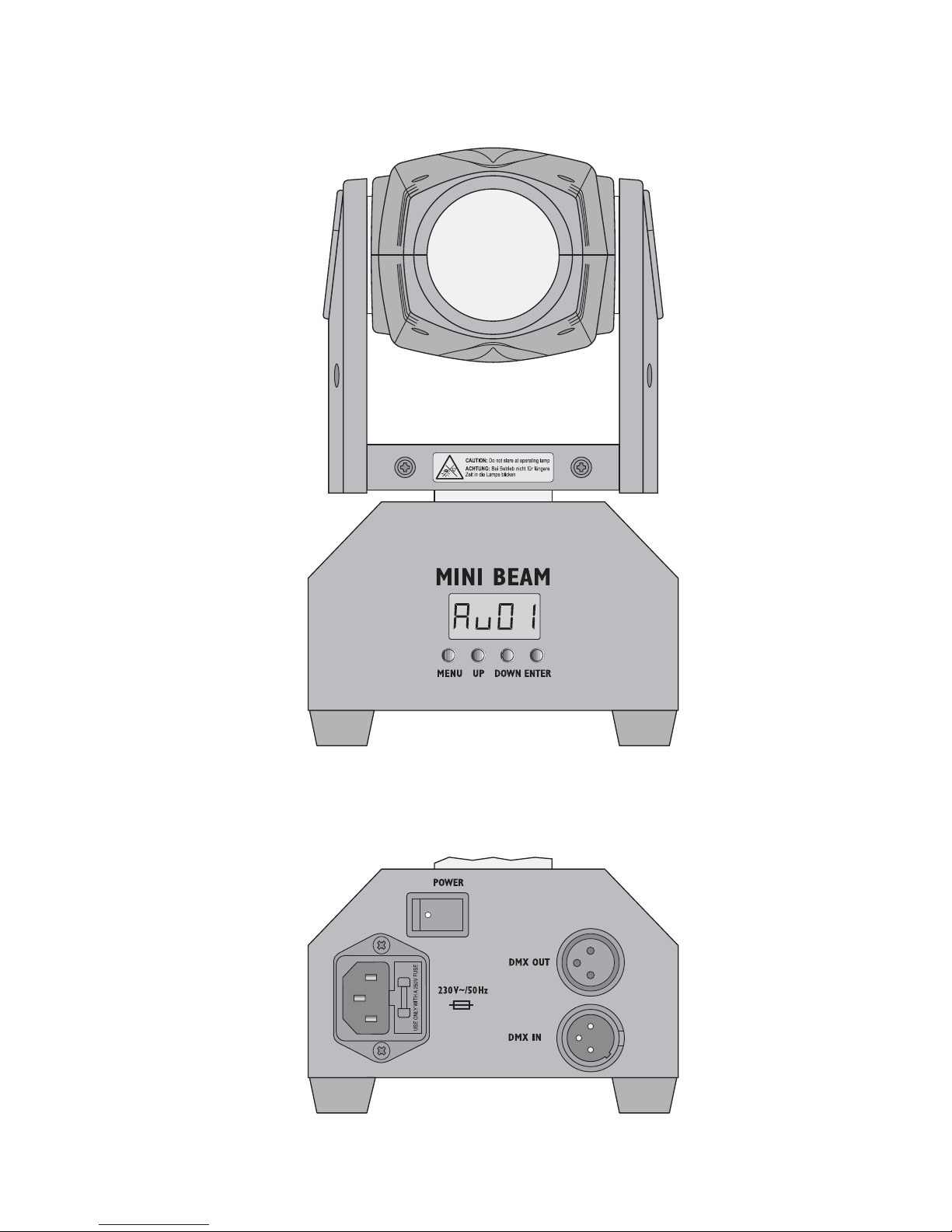
ist das Gerät mit allen Bedienelementen und
Anschlüssen abgebildet.
1 Einsatz- und Aufstell-
möglichkeiten
Das Gerät BEAM-40 /… dient zur Effekt beleuchtung, z. B. auf kleinen Bühnen, auf
Partys und in Diskotheken. Als Lichtquelle ist
eine leistungsstarke 10-W-LED eingesetzt.
Das Gerät ist für die Steuerung über ein
DMX-Lichtsteuergerät ausgelegt. Es kann
aber auch allein betrieben werden, indem
ein Lichtshow-Programm automatisch oder
musikgesteuert abläuft.
Das Gerät lässt sich frei auf einer ebenen
Fläche aufstellen. Alternativ kann es kopfüber
an ein entsprechendes Trägersystem montiert werden. Dazu sind zwei Gewindelöcher
(M 6) auf der Geräteunterseite vorhanden.
2 Hinweise
für den sicheren Gebrauch
Das Gerät entspricht allen relevanten Richt linien der EU und ist deshalb mit
gekenn-
zeichnet.
G
Verwenden Sie das Gerät nur im Innenbereich. Schützen Sie es vor Tropf- und Spritzwasser, hoher Luftfeuchtigkeit und Hitze (zulässiger Einsatztemperaturbereich 0 –40 °C).
G
Die in dem Gerät entstehende Wärme
muss durch Luftzirkulation abgegeben werden. Decken Sie darum die Lüftungsöffnungen des Gehäuses nicht ab.
G
Ziehen Sie sofort den Netzstecker aus der
Steckdose,
1. wenn sichtbare Schäden am Gerät oder
am Netzkabel vorhanden sind,
2. wenn nach einem Sturz oder Ähnlichem
der Verdacht auf einen Defekt besteht,
3. wenn Funktionsstörungen auftreten.
Geben Sie das Gerät in jedem Fall zur
Reparatur in eine Fachwerkstatt.
G
Ziehen Sie den Netzstecker nie am Kabel
aus der Steckdose, fassen Sie immer am
Stecker an.
G
Verwenden Sie für die Reinigung des Ge häuses nur ein trockenes, weiches Tuch,
niemals Wasser oder Chemikalien. Für die
Linse kann auch ein mildes Reinigungsmittel verwendet werden.
G
Wird das Gerät zweckentfremdet, nicht
sicher montiert, nicht richtig angeschlossen, falsch bedient oder nicht fachgerecht
repariert, kann keine Haftung für daraus
resultierende Sach- oder Personenschäden und keine Garantie für das Gerät übernommen werden.
3 Inbetriebnahme
1) Zur Stromversorgung das Gerät über die
Netzbuchse mit dem beiliegenden Netz kabel an eine Steckdose (230 V~ / 50Hz)
anschließen.
2) Das Lichteffektgerät mit dem Schalter
POWER einschalten. Der Schwenkkopf
WARNUNG Blicken Sie nicht für längere
Zeit direkt in die Lichtquelle,
das kann zu Augenschäden
führen.
Beachten Sie, dass sehr schnelle Lichtwechsel bei fotosensiblen Menschen und Epileptikern epileptische Anfälle auslösen können!
WARNUNG Das Gerät wird mit lebensge-
fährlicher Netzspannung versorgt. Nehmen Sie deshalb nie
selbst Eingriffe am Gerät vor
und stecken Sie nichts durch die Lüftungsöffnungen. Es besteht die Gefahr eines elektrischen Schlages.
Soll das Gerät endgültig aus dem
Betrieb genommen werden, übergeben Sie es zur umweltgerechten Entsorgung einem örtlichen Recyclingbetrieb.
Page 5
5
Deutsch
fährt in seine Ausgangsposition. Das Display zeigt den Vorgang mit (Reset) an.
Danach schaltet das Gerät in den zuletzt
gewählten Betriebsmodus. Nach kurzer
Zeit erlischt das Display. Sobald eine der
Bedientasten MENU, DOWN, UP oder
ENTER gedrückt wird, leuchtet es wieder
für kurze Zeit.
3) Nach dem Betrieb das Gerät mit dem
Schalter POWER wieder ausschalten.
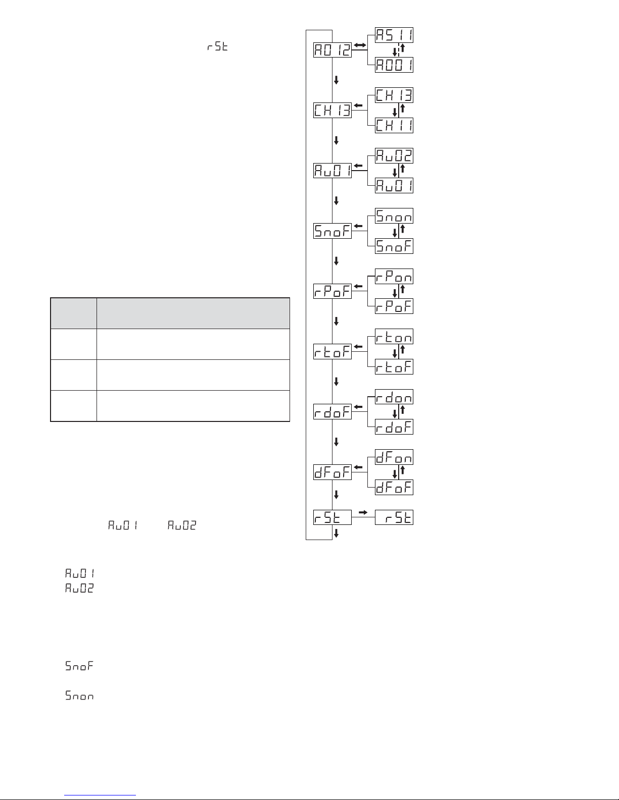
4 Bedienung
Die Bedientasten MENU, UP, DOWN und
ENTER dienen zum Auswählen des Betriebsmodus und verschiedener Funktionen
(Abb. 3). Das Display zeigt dabei den Modus
oder die Einstellung an.
Funktionen der Bedientasten
4.1 Eigenständiger Betrieb
Für den eigenständigen Betrieb kann ein
Lichtshow-Programm ablaufen.
1) Die Taste MENU so oft drücken, bis das
Display oder anzeigt.
2) Die Ablaufgeschwindigkeit mit der Taste
UP oder DOWN wählen:
= schnell
= langsam
Die Auswahl mit der Taste ENTER bestätigen.
3) Soll das Programm musikgesteuert werden, die Taste MENU so oft drücken, bis
angezeigt wird (Sound off). Mit der
Taste UP oder DOWN auf die Anzeige
umschalten (Sound on) und mit der
Taste ENTER bestätigen.
Taste Funktion
MENU
Betriebsmodus und
Einstellmöglichkeiten anwählen
UP
DOWN
Einstellung verändern
ENTER
Einstellung speichern,
gewählte Funktion aktivieren
MENU
ENTER
DOWN
UP
ENTER
ENTER
ENTER
ENTER
ENTER
ENTER
ENTER
DOWN
UP
DOWN
UP
DOWN
UP
DOWN
UP
DOWN
UP
DOWN
UP
DOWN
UP
ENTER
MENU
MENU
MENU
MENU
MENU
MENU
MENU
MENU
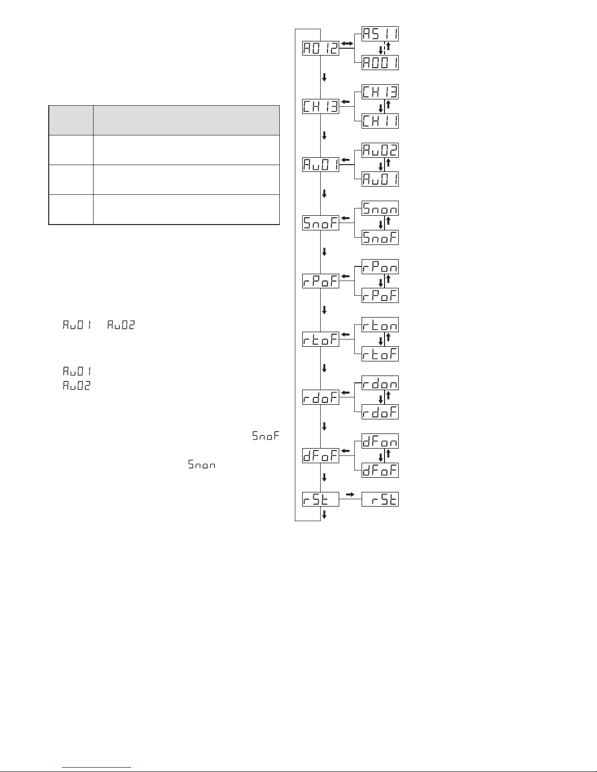
Bedienmenü fett = Werkseinstellung
DMX-Betrieb und
Startadresse einstellen;
Adresse ab Werk: 001
Anzahl der DMX-Kanäle
BEAM-40/ WS:
7 oder 9
BEAM-40/ RGBW:
11 oder 13
Reset
Lichtshow-Programm
01 = schnell
02 = langsam
Musiksteuerung
oF = aus, on = ein
Schwenkkopf entgegen gesetzt drehen:
oF = nein, on = ja
Schwenkkopf entgegen gesetzt neigen:
oF = nein, on = ja
Displaydarstellung
überkopf:
oF = nein, on = ja
Zurücksetzen auf die
Werkeinstellung
oF = nein, on = ja
4.2 Betrieb mit einem DMX-Steuergerät
DMX ist die Abkürzung für Digital Multiplex
und bedeutet digitale Steuerung von mehreren DMX-Geräten über eine gemeinsame
Steuerleitung. Die Funktionen der Kanäle und
die DMX-Werte sind im Kapitel 4.2.3 angegeben. Zur Bedienung über ein DMX-Lichtsteuergerät (z. B. DMX-1440 oder DMX-510USB)
ist die folgende Anzahl von DMX-Kanälen
vorhanden:
BEAM-40/ RGBW: 11 oder 13 Kanäle
BEAM-40/ WS: 7 oder 9 Kanäle
Page 6
6
Deutsch
4.2.1 Anschluss
Für die DMX-Verbindung sind 3-polige XLRAn schlüsse mit folgender Kontaktbelegung
vorhanden:
Pin 1 = Masse, 2 = DMX
-
, 3 = DMX+
Zum Anschluss sollten spezielle Kabel für die
DMX-Signalübertragung verwendet werden
(z. B. Kabel der CDMXN-Serie von „img Stage
Line“). Bei Leitungslängen ab 150 m und bei
der Steuerung von mehr als 32 Geräten über
einen DMX-Ausgang wird grundsätzlich das
Zwischenschalten eines DMX-Aufholverstärkers empfohlen (z. B. SR-103DMX von „img
Stage Line“)
1) Den Eingang DMX IN mit dem DMX-Ausgang des Lichtsteuergerätes oder eines
anderen DMX-gesteuerten Gerätes verbinden.
2) Den Ausgang DMX OUT mit dem DMXEingang des nächsten DMX-Gerätes verbinden. Dessen Ausgang wieder mit dem
Eingang des nachfolgenden DMX-Gerätes
verbinden usw., bis alle DMX-gesteuerten
Geräte in einer Kette angeschlossen sind.
3) Um Störungen bei der Signalübertragung
auszuschließen, sollte bei langen Leitungen bzw. bei einer Vielzahl von hintereinandergeschalteten Geräten der DMX-Ausgang des letzten DMX-Gerätes der Kette
mit einem 120-Ω-Widerstand (> 0,3 W)
abgeschlossen werden: In die DMX-Ausgangsbuchse einen entsprechenden Ab schlussstecker (z. B. DLT-123 von „img
Stage Line“) stecken.
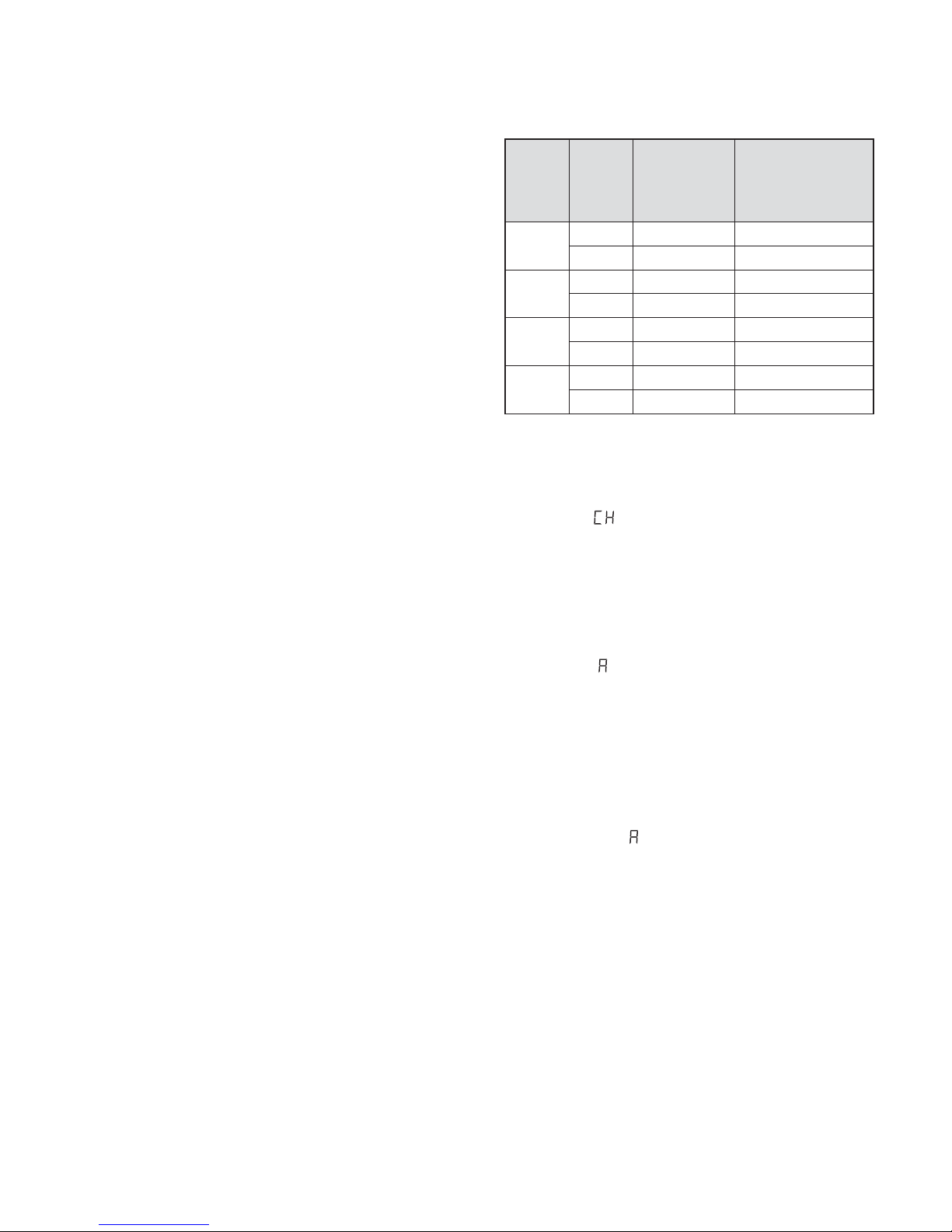
4.2.2 Anzahl der DMX-Kanäle
und Startadresse einstellen
Um alle am Lichtsteuergerät angeschlossenen DMX-Geräte separat bedienen zu können, muss jedes Gerät eine eigene Startadresse erhalten. Soll der erste DMX-Kanal
des BEAM-40 vom Lichtsteuergerät z. B.
über die DMX-Adresse 6 gesteuert werden,
am BEAM-40 die Startadresse 6 einstellen.
Die übrigen DMX-Kanäle des BEAM-40 sind
dann automatisch den darauffolgenden Adressen zugeordnet. Beispiele mit verschiedenen
Startadressen:
DMX-Adressenbelegung
1
BEAM-40 / WS, 2BEAM-40/ RGBW
1) Die Taste MENU so oft drücken, bis das
Display (für Channel) und eine Zahl an zeigt.
2) Die gewünschte Kanalanzahl mit der Taste
UP oder DOWN einstellen und mit der
Taste ENTER bestätigen.
3) Die Taste MENU so oft drücken, bis das
Display (für Adresse) und die aktuelle
Startadresse anzeigt.
4) Die gewünschte Adresse mit der Taste UP
oder DOWN einstellen und mit der Taste
ENTER bestätigen.
5) Damit der Moving-Head per DMX ge steuert werden kann, muss immer der
Menüpunkt für die Startadresse angewählt bleiben. Sobald ein DMX-Steuersignal empfangen wird, leuchtet ein Punkt im
Display. Die DMX-Funktionen finden Sie
im nächsten Kapitel.
Tipp: Werden zwei oder mehrere BEAM-40 synchron über dieselbe Startadresse gesteuert, die
Dreh- und /oder die Neigerichtung des Schwenkkopfs bei einem oder mehreren Geräten entgegengesetzt einstellen (Kap. 4.3). So bewegen sich die
Schwenkköpfe z. B. bei einem Gerätepaar spiegelbildlich.
Anzahl
der
DMX-
Kanäle
Start-
adresse
vom
BEAM-40
belegte
Adressen
nächstmögliche
Startadresse für
das nachfolgende
DMX-Gerät
7
1
1 1– 7 8
6 6– 12 13
9
1
1 1– 9 10
24 24 – 32 33
11
2
1 1– 11 12
502 502 – 512 —
13
2
1 1– 13 14
60 60 – 72 73
Page 7
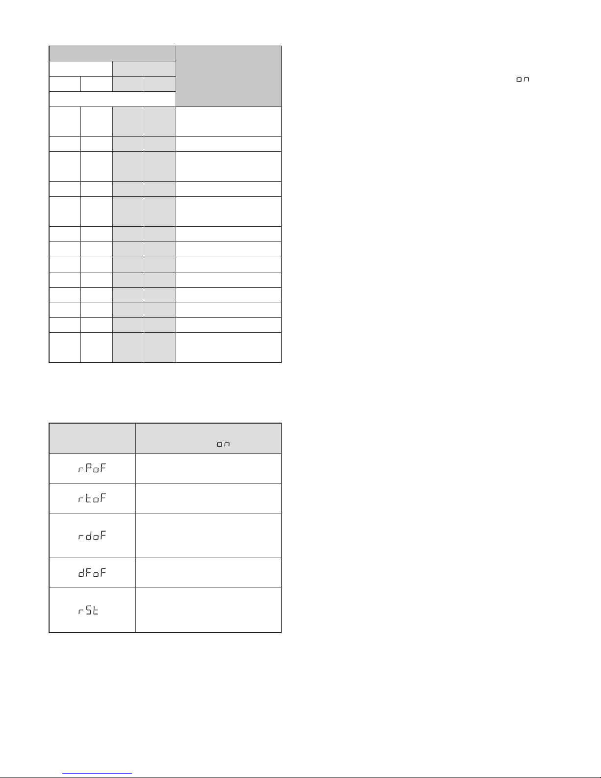
4.2.3 DMX-Kanäle und -Funktionen
DMX-Übersicht
4.3 Zusätzliche Funktionen
Zusatzfunktionen
1) Die Funktion mit der Taste MENU über den
zugehörigen Menüpunkt anwählen (siehe
auch Abb. 3).
2) Mit der Taste UP oder DOWN auf ..
schalten (für ein Reset nicht erforderlich
und nicht möglich).
3) Zum Aktivieren der Einstellung die Taste
ENTER drücken.
5 Technische Daten
Datenprotokoll: . . . . . . . . . . DMX 512
Anzahl der DMX-Kanäle
BEAM-40 / RGBW: . . . . . 11 oder 13
BEAM-40 / WS: . . . . . . . . 7 oder 9
Lichtquelle
BEAM-40 / RGBW: . . . . . 1 × RGBW-LED
BEAM-40 / WS: . . . . . . . . 1 × LED, weiß
Leistungsaufnahme: . . . . 10 W
Abstrahlwinkel: . . . . . . . . 5°
Drehwinkel (Pan): . . . . . . . 540°
Neigungswinkel (Tilt): . . . . 270°
DMX-Anschlüsse: . . . . . . . XLR, 3-polig
Pinbelegung: . . . . . . . . . Pin 1 = Masse
Pin 2 = DMX
-
Pin 3 = DMX+
Stromversorgung: . . . . . . . 230 V~ / 50 Hz
Leistungsaufnahme: . . . . . max. 40 VA
Abmessungen (B × H × T): 13 × 20 × 13 cm
Gewicht: . . . . . . . . . . . . . . . 2,8 kg
Änderungen vorbehalten.
Kanalanzahl
Funktion
DMX-Werte 0 – 255,
wenn nicht
anders angeben
BEAM-40/ WS B.-40/ RGBW
CH07 CH 09 CH11 CH13
DMX-Kanal
11
1 1
Kopf drehen (Pan),
grob
22
2 2 Kopf drehen, fein
33
3 3
Kopf neigen (Tilt),
grob
44
4 4 Kopf neigen, fein
55
5 5
Pan- / Tilt-
Geschwindigkeit
66
6 6 Dimmer
77
7 7 Stroboskop
——
8 8 Helligkeit Rot
——
9 9 Helligkeit Grün
——
10 10 Helligkeit Blau
——
11 11 Helligkeit Weiß
—8
— 12 Lichtshow-Programm
—9
— 13
Reset bei DMX-Wert
150 – 200
7
Deutsch
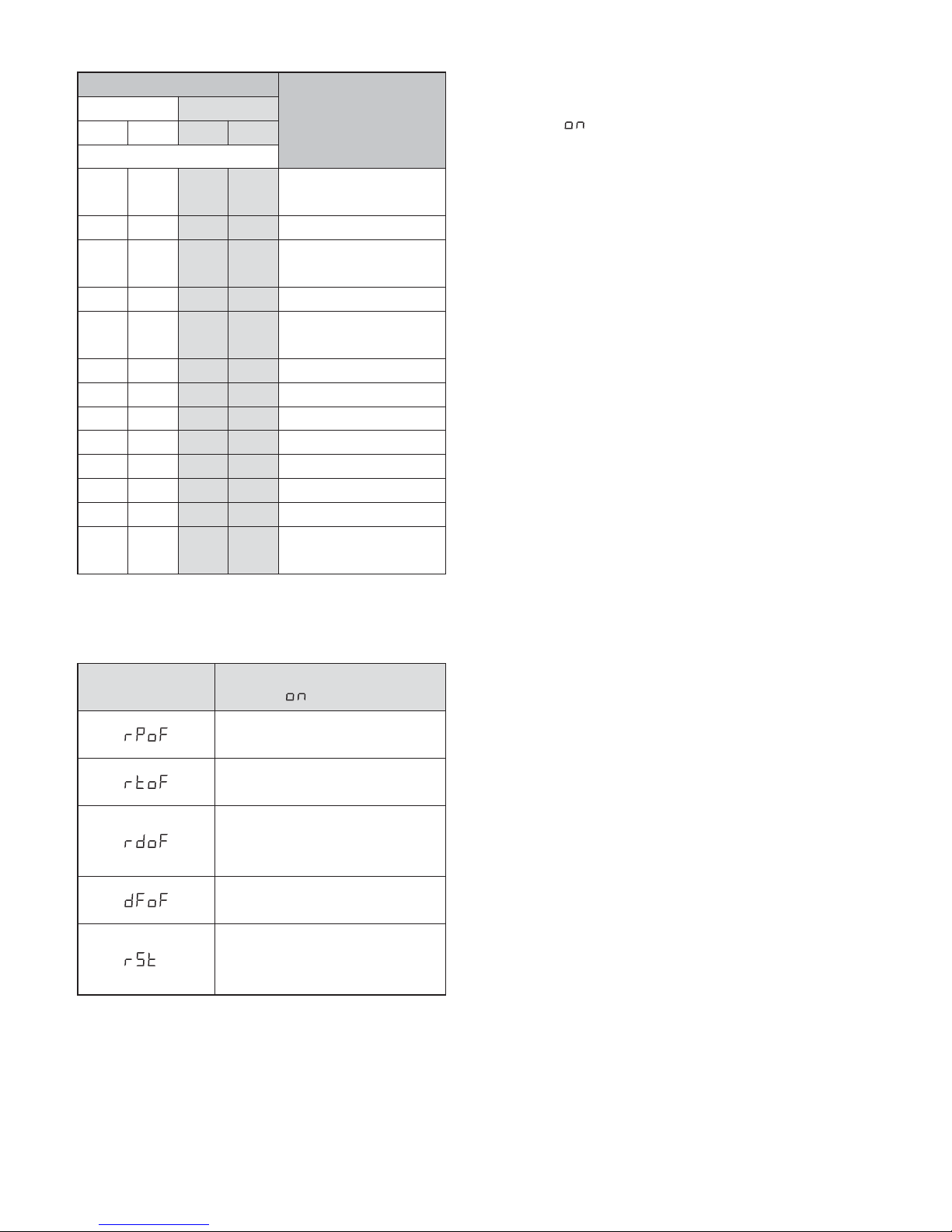
Menüpunkt
Funktion bei der
Einstellung auf . .
Schwenkkopf dreht sich
entgegengesetzt
Schwenkkopf neigt sich
entgegengesetzt
Anzeigen im Display
für eine Montage kopfüber
um 180° gedreht
Zurücksetzen auf die Werkseinstellung (fett in Abb. 3)
Taste ENTER drücken:
Reset – Der Schwenkkopf
fährt in die Ausgangsposition
Diese Bedienungsanleitung ist urheberrechtlich für MONACOR®INTERNATIONAL GmbH & Co. KG ge schützt. Eine Reproduktion für eigene kommerzielle Zwecke – auch auszugsweise – ist untersagt.
Page 8
LED Beam Moving Head
These instructions are intended for users with
basic knowledge in DMX control. Please read
the instructions carefully prior to operation
and keep them for later reference. On page 2,
you will find the unit with all operating elements and connections.
1 Applications/ Setting Up
The unit BEAM-40 /… is used for effect lighting, e. g. on small stages, at parties or in
clubs. As a light source, it uses a powerful
10 W LED. The unit is designed for operation
via a DMX light controller; however, it can also
be operated independently, running an automatic or music-controlled light show program.
Place the unit on a flat surface as desired.
Alternatively, install it upside down on a suitable lighting support system, using the two
threaded holes (M 6) on its lower side.
2 Safety Notes
The unit corresponds to all relevant directives
of the EU and is therefore marked with
.
G
The unit is suitable for indoor use only. Protect it against dripping water and splash
water, high air humidity and heat (admissible ambient temperature range: 0 – 40 °C).
G
The heat produced inside the unit must be
dissipated by air circulation; therefore,
never cover the air vents of the housing.
G
Immediately disconnect the mains plug
from the socket
1. if the unit or the mains cable is visibly
damaged,
2. if a defect might have occurred after the
unit was dropped or suffered a similar
accident,
3. if malfunctions occur.
In any case the unit must be repaired by
skilled personnel.
G
Never pull the mains cable to disconnect
the mains plug from the socket, always
seize the plug.
G
For cleaning the housing, only use a dry,
soft cloth; never use water or chemicals.
For cleaning the lens, you may also use a
mild detergent.
G
No guarantee claims for the unit and no liability for any resulting personal damage or
material damage will be accepted if the unit
is used for other purposes than originally
intended, if it is not safely installed or not
correctly connected or operated, or if it is
not repaired in an expert way.
3 Setting into Operation
1) For power supply, connect the unit to a
mains socket (230 V~ / 50Hz) via the mains
cable provided.
2) Switch on the light effect unit with the
switch POWER. The moving head will go
to its starting position. (Reset) will be
displayed. Then the unit will go to the operating mode most recently selected. The
display will extinguish after a short while.
As soon as one of the control buttons
MENU, DOWN, UP or ENTER is pressed,
the display will light up again for a short
while.
3) After operation, switch off the unit with the
switch POWER.
WARNING To prevent damage to your
eyes, never look directly into
the light source for any length of
time.
Please note that fast changes in lighting may
trigger epileptic seizures with photosensitive
persons or persons with epilepsy!
If the unit is to be put out of operation
definitively, take it to a local recycling
plant for a disposal which is not
harmful to the environment.
WARNING The unit uses dangerous mains
voltage. Leave servicing to
skilled personnel and do not
insert anything into the air
vents; inexpert handling may result in electric shock.
8
English
Page 9
4 Operation
The control buttons MENU, UP, DOWN and
ENTER are used to select the operating
mode and various functions (fig. 3). The
mode or the setting will be displayed.
Functions of the control buttons
4.1 Independent operation
For independent operation, a light show program can be activated:
1) Press the button MENU repeatedly until
or is displayed.
2) Select the program speed with the button
UP or DOWN:
= fast
= slow
Press the button ENTER to confirm.
3) For a music-controlled program, press
the button MENU repeatedly until
(Sound off) is displayed. Press the button
UP or DOWN to go to (Sound on)
and press the button ENTER to confirm.
Button Function
MENU
To select the operating mode and
the setting options
UP
DOWN
To change the setting
ENTER
To save the setting,
to activate the function selected
9
English
4.2 Operation with a DMX controller
DMX stands for Digital Multiplex and means
digital control of multiple DMX units via a
common control line. The functions of the
channels and the DMX values can be found
in chapter 4.2.3. For control via a DMX controller (e. g. DMX-1440 or DMX-510USB), the
following numbers of DMX channels are
available:
BEAM-40/ RGBW: 11 or 13 channels
BEAM-40/ WS: 7 or 9 channels
MENU
ENTER
DOWN
UP
ENTER
ENTER
ENTER
ENTER
ENTER
ENTER
ENTER
DOWN
UP
DOWN
UP
DOWN
UP
DOWN
UP
DOWN
UP
DOWN
UP
DOWN
UP
ENTER
MENU
MENU
MENU
MENU
MENU
MENU
MENU
MENU
Control menu bold = factory setting
Setting of DMX mode and
start address, factory-set
address: 001
Number of DMX channels
BEAM-40/ WS:
7 or 9
BEAM-40/ RGBW:
11 or 13
Reset
Light show program
01 = fast
02 = slow
Music control
oF = off, on
Opposite pan direction of
moving head:
oF = no, on = yes
Opposite tilt direction of
moving head:
oF = no, on = yes
Display mode for upsidedown installation:
oF = no, on = yes
Reset to factory settings
oF = no, on = yes
Page 10

4.2.1 Connection
For DMX connection, 3-pole XLR connectors
with the following pin configurations are available:
Pin 1 = ground, 2 = DMX
-
, 3 = DMX+
For connection, special cables for DMX signal transmission are recommended (e. g.
cables of the CDMXN series from “img Stage
Line”). For cable lengths exceeding 150 m
and when controlling more than 32 units via a
single DMX output, it is generally recommended to insert a DMX level matching
amplifier (e. g. SR-103DMX from “img Stage
Line”).
1) Connect the input DMX IN to the DMX output of the light controller or of another
DMX-controlled unit.
2) Connect the output DMX OUT to the DMX
input of the second DMX-controlled unit.
Proceed in the same way to connect the
output of the second unit to the input of the
third unit etc. until all DMX-controlled units
have been connected in a chain.
3) To prevent interference in signal transmission, in case of long cables or a multitude
of units connected in series, terminate the
DMX output of the last DMX unit in the
chain with a 120 Ω resistor (> 0.3 W): Connect a corresponding terminating plug
(e. g. DLT-123 from “img Stage Line”) to
the DMX output jack.
4.2.2 Setting the number of DMX channels
and the start address
For separate control of all DMX units connected to the light controller, each unit must
have its own start address. Example: If the
first DMX channel of the BEAM-40 is to be
controlled by the light controller via DMX
address 6, set the start address on the
BEAM-40 to 6. All other DMX channels of the
BEAM-40 will be automatically assigned to
the subsequent addresses. Examples with
different start addresses:
DMX address assignment
1
BEAM-40 / WS, 2BEAM-40 / RGBW
1) Press the button MENU repeatedly until
the display shows (channel) and a number.
2) Set the desired number of channels with
the button UP or DOWN and press the button ENTER to confirm.
3) Press the button MENU repeatedly until
the display shows (address) and the current start address.
4) Set the desired address with the button UP
or DOWN and press the button ENTER to
confirm.
5) For DMX control of the moving head, the
menu item for the start address must be
selected all the time. As soon as a DMX
control signal is received, a dot will light up
on the display. The DMX functions can be
found in the next chapter.
Hint: When two or multiple BEAM-40 are synchronously controlled via the same start address, set the
moving head of one or multiple units to the opposite
pan direction and / or tilt direction (chapter 4.3). Thus,
with a pair of units, the heads will move in opposite
directions (mirror-inverted).
Number
of DMX
channels
Start
address
Addresses
used by
BEAM-40
Next possible start
address for the
following DMX unit
7
1
1 1– 7 8
6 6– 12 13
9
1
1 1– 9 10
24 24 – 32 33
11
2
1 1– 11 12
502 502 – 512 —
13
2
1 1– 13 14
60 60 – 72 73
10
English
Page 11
4.2.3 DMX channels and functions
DMX overview
4.3 Additional functions
Additional functions
1) Go to the corresponding menu item and
select the function with the button MENU
(also see fig. 3).
2) Go to . . with the button UP or DOWN
(not necessary and not possible for reset).
3) To activate the setting, press the button
ENTER.
5 Specifications
Data protocol: . . . . . . . . . . DMX 512
Number of DMX channels
BEAM-40 / RGBW: . . . . . 11 or 13
BEAM-40 / WS: . . . . . . . . 7 or 9
Light source
BEAM-40 / RGBW: . . . . . 1 × RGBW LED
BEAM-40 / WS: . . . . . . . . 1 × LED, white
Power consumption: . . . . 10 W
Beam angle: . . . . . . . . . . 5°
Pan angle: . . . . . . . . . . . . . 540°
Tilt angle: . . . . . . . . . . . . . . 270°
DMX connections: . . . . . . . XLR, 3 poles
Pin configuration: . . . . . . Pin 1 = ground
Pin 2 = DMX
-
Pin 3 = DMX+
Power supply: . . . . . . . . . . 230 V~ / 50 Hz
Power consumption: . . . . . 40 VA max.
Dimensions (W × H × D): . . 13 × 20 × 13 cm
Weight: . . . . . . . . . . . . . . . . 2.8 kg
Subject to technical modification.
Number of channels
Function
DMX values 0 – 255
unless otherwise
specified
BEAM-40/ WS B.-40/ RGBW
CH07 CH 09 CH11 CH13
DMX channel
11
1 1
Pan,
coarse
22
2 2 Pan, fine
33
3 3
Tilt,
coarse
44
4 4 Tilt, fine
55
5 5
Pan / tilt
speed
66
6 6 Dimmer
77
7 7 Stroboscope
——
8 8 Brightness of red
——
9 9 Brightness of green
——
10 10 Brightness of blue
——
11 11 Brightness of white
—8
— 12 Light show program
—9
— 13
Reset at DMX value
150 – 200
11
English
All rights reserved by MONACOR®INTERNATIONAL GmbH & Co. KG. No part of this instruction manual
may be reproduced in any form or by any means for any commercial use.
Menu item
Functions with the
setting . .
Opposite pan direction
of moving head
Opposite tilt direction
of moving head
Display mode
for upside-down installation
(rotated by 180°)
Reset to factory settings
(bold in fig. 3)
Press button ENTER:
Reset – The head will go to its
starting position.
Page 12

Lyre à LED
Cette notice sʼadresse aux utilisateurs ayant
des connaissances de base dans la gestion
DMX. Veuillez lire la présente notice avec
attention avant le fonctionnement et conservez-la pour pouvoir vous y reporter ultérieurement. Vous trouverez sur la page 2 une
représentation de lʼappareil avec les éléments et branchements.
1 Possibilités dʼutilisation
et de positionnement
La BEAM-40 /… permet de créer des effets
lumineux, par exemple sur de petites scènes,
dans des soirées ou clubs. Une LED 10 W
puissante est la source lumineuse. Lʼappareil
est prévu pour une gestion via un contrôleur
DMX. Il peut également fonctionner seul et
faire défiler un programme show lumière
automatique ou géré par la musique.
Lʼappareil peut être posé librement sur
une surface plane. Il peut être monté également sur un portique, à lʼenvers. Utilisez les
deux trous filetés (M6) sur la face inférieure
de lʼappareil.
2 Conseils dʼutilisation
et de sécurité
Lʼappareil répond à toutes les directives
nécessaires de lʼUnion européenne et porte
donc le symbole .
G
Lʼappareil nʼest conçu que pour une utilisation en intérieur. Protégez-le de tout type
de projections d'eau, des éclaboussures,
d'une humidité élevée de l'air et de la chaleur (plage de température de fonctionnement autorisée : 0 – 40 °C).
G
La chaleur dégagée par lʼappareil doit être
évacuée par une circulation de lʼair : en aucun cas, les ouïes de ventilation du boîtier
ne doivent pas être obturées.
G
Débranchez l'appareil immédiatement du
secteur lorsque :
1. des dommages visibles apparaissent sur
l'appareil ou sur le cordon secteur,
2. après une chute ou un cas similaire, vous
avez un doute sur l'état de l'appareil,
3. des dysfonctionnements apparaissent.
Dans tous les cas, les dommages doivent
être réparés par un technicien spécialisé.
G
Ne débranchez jamais l'appareil en tirant
sur le cordon secteur ; retirez toujours le
cordon secteur en tirant la fiche.
G
Pour nettoyer le boîtier, utilisez uniquement
un chiffon sec et doux, en aucun cas de
produits chimiques ou dʼeau. Pour la lentille, vous pouvez également utiliser un produit de nettoyage doux.
G
Nous déclinons toute responsabilité en cas
de dommages matériels ou corporels résultants si lʼappareil est utilisé dans un but autre
que celui pour lequel il a été conçu, sʼil nʼest
pas monté dʼune manière sûre, sʼil nʼest pas
correctement branché ou utilisé ou sʼil nʼest
pas réparée par une personne habilitée, en
outre, la garantie deviendrait caduque.
3 Fonctionnement
1) Pour lʼalimentation, reliez lʼappareil via la
prise secteur à une prise 230 V~ / 50 Hz
avec le cordon secteur livré.
CARTONS ET EMBALLAGE
PAPIER À TRIER
AVERTISSEMENT Ne regardez jamais directe-
ment la source lumineuse,
cela pourrait causer des
troubles de la vision.
N'oubliez pas que des changements très
rapides de lumière peuvent déclencher des
crises d'épilepsie chez les personnes photosensibles et épileptiques.
Lorsque lʼappareil est définitivement
retiré du service, vous devez le déposer dans une usine de recyclage
adaptée pour contribuer à son élimination non polluante.
AVERTISSEMENT Lʼappareil est alimenté par
une tension dangereuse.
Ne touchez jamais l'inté-
rieur de l'appareil et n'insérez rien dans les ouïes de ventilation !
Risque de décharge électrique.
12
Français
Page 13

2) Allumez lʼappareil avec lʼinterrupteur
POWER. La tête se met sur sa position de
départ. Lʼaffichage indique le processus
avec (Reset). Ensuite lʼappareil va au
dernier mode de fonctionnement sélectionné. Peu de temps après, lʼaffichage
sʼéteint. Dès quʼune touche de commande
MENU, DOWN, UP ou ENTER est activée,
il se rallume brièvement.
3) Après le fonctionnement, éteignez lʼappareil avec lʼinterrupteur POWER.
4 Utilisation
Les touches MENU, UP, DOWN et ENTER
permettent de sélectionner le mode de fonctionnement et différentes fonctions (schéma 3).
Lʼaffichage indique le réglage ou le mode.
Fonctions des touches de commande
4.1 Fonctionnement autonome
Pour un fonctionnement autonome, un programme show lumière peut être activé :
1) Appuyez sur la touche MENU de manière
répétée jusquʼà ce que lʼaffichage indique
ou .
2) Sélectionnez la vitesse de défilement avec
la touche UP ou DOWN :
= rapide
= lent
Confirmez la sélection avec la touche
ENTER.
3) Si le programme doit être géré par la
musique, appuyez sur la touche MENU de
manière répétée jusquʼà ce que
(Sound off) soit affiché. Avec la touche UP
ou DOWN, commutez sur lʼaffichage
(Sound on) et confirmez avec la touche
ENTER.
Touche Fonction
MENU
sélection du mode de fonctionnement
et des possibilités de réglage
UP
DOWN
modification du réglage
ENTER
mémorisation du réglage,
activation de la fonction sélectionnée
13
Français
4.2 Fonctionnement avec
un contrôleur DMX
DMX est l'abréviation de Digital Multiplex et
signifie une commande digitale de plusieurs
appareils DMX via un câble commun de commande. Vous trouverez les fonctions des
canaux et les valeurs DMX dans le chapi tre 4.2.3. Pour une gestion via un contrôleur
DMX (p. ex. DMX-1440 ou DMX-510USB), le
nombre de canaux DMX est le suivant :
BEAM-40 / RGBW 11 ou 13 canaux
BEAM-40 / WS : 7 ou 9 canaux
MENU
ENTER
DOWN
UP
ENTER
ENTER
ENTER
ENTER
ENTER
ENTER
ENTER
DOWN
UP
DOWN
UP
DOWN
UP
DOWN
UP
DOWN
UP
DOWN
UP
DOWN
UP
ENTER
MENU
MENU
MENU
MENU
MENU
MENU
MENU
MENU
Menu de commande en gras : réglages d'usine
Fonctionnement DMX et
réglage de lʼadresse de
démarrage ; adresse réglée en usine : 001
Nombre de canaux DMX
BEAM-40/ WS:
7 ou 9
BEAM-40/ RGBW:
11 ou 13
Reset
Programme show lumière
01 = rapide
02 = lent
Gestion par la musique
oF = désactivée,
on = activée
Tête : rotation inversée
oF = désactivée,
on = activée
Tête : inclinaison inversée
oF = désactivée,
on = activée
Visualisation affichage
inversée :
oF = désactivée,
on = activée
Réinitialisation sur les
réglages dʼusine
oF = désactivée,
on = activée
Page 14

4.2.1 Branchement
Pour la connexion DMX, des branchements
XLR 3 pôles avec la configuration de contact
suivante sont prévus :
Pin 1 = masse, 2 = DMX
-
, 3 = DMX+
Pour le branchement, il est recommandé
d'utiliser des câbles spécifiques pour la transmission de signaux DMX (par exemple
câbles de la série CDMXN de “img Stage
Line”). Pour des longueurs de liaison à partir
de 150 m et pour une gestion de plus de 32
appareils via une seule sortie DMX, il est
recommandé d'insérer un amplificateur DMX
de signal (par exemple SR-103DMX de “img
Stage Line”).
1) Reliez lʼentrée DMX IN à la sortie DMX du
contrôleur ou dʼun autre appareil géré par
DMX.
2) Reliez la sortie DMX OUT à lʼentrée DMX
du prochain appareil DMX. Reliez sa sortie à lʼentrée de lʼappareil DMX suivant et
ainsi de suite de manière à ce que tous les
appareils gérés par DMX forment une
chaîne.
3) Pour éviter les perturbations lors de la
transmission du signal, il convient, pour de
longs câbles ou pour une multitude dʼappareils branchés les uns derrière les
autres, de terminer la sortie DMX du dernier appareil DMX de la chaîne avec une
résistance 120 Ω (> 0,3 W) : mettez un
bouchon (par exemple DLT-123 de “img
Stage Line“) dans la prise de sortie DMX.
4.2.2 Réglage du nombre de canaux DMX
et de lʼadresse de démarrage
Pour pourvoir utiliser séparément tous les
appareils DMX reliés au contrôleur, il faut que
chaque appareil aie une adresse de démarrage propre. Si le premier canal DMX de la
BEAM-40 doit être géré par le contrôleur, par
exemple, via lʼadresse DMX 6, réglez sur la
BEAM-40, lʼadresse de démarrage 6. Les
autres canaux DMX de la BEAM-40 sont
automatiquement attribués aux adresses suivantes. Exemples avec différentes adresses
de démarrage :
Configuration des adresses DMX
1
BEAM-40 / WS, 2BEAM-40/ RGBW
1) Appuyez sur la touche MENU de manière
répétée jusquʼà ce que lʼaffichage indique
(pour Channel) et un chiffre.
2) Réglez le nombre souhaité de canaux
avec la touche UP ou DOWN et confirmez
avec ENTER.
3) Appuyez sur la touche MENU de manière
répétée jusquʼà ce que sur lʼaffichage, la
lettre (pour adresse) et lʼadresse de
démarrage actuelle soient visibles.
4) Réglez l'adresse souhaitée avec la touche
UP ou DOWN et confirmez avec la touche
ENTER.
5) Pour que la lyre puisse être gérée par
DMX, il faut que le point de menu pour
adresse de démarrage soit toujours sélectionné. Dès quʼun signal de commande
DMX est reçu, un point est visible sur lʼaffichage. Vous trouverez les fonctions DMX
dans le chapitre suivant.
Conseil : Si deux ou plusieurs BEAM-40 sont gérées
de manière synchrone via la même adresse de
démarrage, réglez le sens de rotation et dʼinclinaison
de la tête pour un ou plusieurs appareils à lʼinverse
(chapitre 4.3). Les têtes se déplacent alors, par
exemple pour une paire dʼappareils, dans les sens
opposés.
Nombre
de
canaux
DMX
Adresse
de
démar-
rage
Adresses
utilisées par
la BEAM-40
Adresse de démar-
rage suivante pos-
sible pour lʼappareil
DMX suivant
7
1
1 1– 7 8
6 6– 12 13
9
1
1 1– 9 10
24 24 – 32 33
11
2
1 1– 11 12
502 502 – 512 —
13
2
1 1– 13 14
60 60 – 72 73
14
Français
Page 15

4.2.3 Canaux DMX et fonctions DMX
Aperçu DMX
4.3 Fonctions supplémentaires
Fonctions supplémentaires
1) Sélectionnez la fonction avec la touche
MENU via le point de menu correspondant
(voir également schéma 3).
2) Avec la touche UP ou DOWN, commutez
sur . . (pas nécessaire et impossible
pour réinitialisation).
3) Pour activer le réglage, appuyez sur la
touche ENTER.
5 Caractéristiques techniques
Protocole données : . . . . . . DMX 512
Nombre de canaux DMX
BEAM-40 / RGBW : . . . . . 11 ou 13
BEAM-40 / WS : . . . . . . . . 7 ou 9
Source lumineuse
BEAM-40 / RGBW : . . . . . 1 × LED RGBW
BEAM-40 / WS : . . . . . . . . 1 × LED, blanc
Consommation : . . . . . . . 10 W
Angle de rayonnement : . 5°
Angle rotation (Pan) : . . . . . 540°
Angle inclinaison (Tilt) : . . . 270°
Branchements DMX : . . . . . XLR, 3 pôles
Configuration : . . . . . . . . Pin 1 = Masse
Pin 2 = DMX
-
Pin 3 = DMX+
Alimentation : . . . . . . . . . . . 230 V~ / 50 Hz
Consommation : . . . . . . . . . 40 VA max.
Dimensions (L × H × P) : . . 13 × 20 × 13 cm
Poids : . . . . . . . . . . . . . . . . 2,8 kg
Tout droit de modification réservé.
Nombre de canaux
Fonction
valeurs DMX 0 – 255
si rien dʼautre
nʼest indiqué
BEAM-40/ WS B.-40/ RGBW
CH07 CH 09 CH11 CH13
Canal DMX
11
1 1
rotation tête (Pan),
grossier
22
2 2 rotation tête, fin
33
3 3
inclinaison tête (Tilt),
grossier
44
4 4 inclinaison tête, fin
55
5 5
vitesse
Pan / Tilt
66
6 6 dimmer
77
7 7 stroboscope
——
8 8 luminosité rouge
——
9 9 luminosité vert
——
10 10 luminosité bleu
——
11 11 luminosité blanc
—8
— 12
programme show
lumière
—9
— 13
reset pour valeur DMX
150 – 200
15
Français
Notice dʼutilisation protégée par le copyright de MONACOR®INTERNATIONAL GmbH & Co. KG. Toute
reproduction même partielle à des fins commerciales est interdite.
Point menu
Fonction avec
réglage sur . .
la tête tourne en sens
inverse
la tête sʼincline en sens
inverse
indication sur lʼaffichage
inversée de 180° pour
un montage inversé
réinitialisation sur
les réglages dʼusine
(en gras sur le schéma 3)
Appuyez sur la touche ENTER :
Reset – la tête revient
à la position de départ
Page 16

LED Beam Moving Head
Queste istruzioni sono rivolte allʼutente con
conoscenze base dei comandi DMX. Vi preghiamo di leggerle attentamente prima della
messa in funzione e di conservarle per un
uso futuro. A pagina 2 vedrete l'apparecchio
con tutti gli elementi di comando e collegamenti.
1 Possibilità d'impiego
e di collocazione
L'apparecchio BEAM-40 /… serve per l'illuminazione a effetto, su palcoscenici piccoli,
durante party e in discoteche. Come fonte di
luce è inserito un LED potente di 10 W. L'apparecchio è previsto per il comando tramite
unʼunità DMX di comando luce. Tuttavia, può
essere usato anche in modo autonomo, con
un programma di light-show che si svolge
automaticamente o comandato dalla musica.
Lʼapparecchio può essere collocato liberamente su un piano pari. In alternativa può
essere montato a rovescio su una traversa.
Per tale caso, sul lato inferiore dell'apparecchio si trovano due fori filettati (M 6).
2 Avvertenze per lʼuso sicuro
Lʼapparecchio è conforme a tutte le direttive
rilevanti dellʼUE e pertanto porta la sigla
.
G
Usare lʼapparecchio solo allʼinterno di locali
e proteggerlo dall'acqua gocciolante e dagli
spruzzi d'acqua, da alta umidità dell'aria e
dal calore (temperatura dʼimpiego ammessa fra 0 e 40 °C).
G
Devʼessere garantita la libera circolazione
dellʼaria per dissipare il calore che viene
prodotto allʼinterno dell'apparecchio. Non
coprire in nessun modo le fessure dʼaerazione del contenitore.
G
Staccare subito la spina dalla presa di rete
se:
1. lʼapparecchio o il cavo rete presentano
dei danni visibili;
2. dopo una caduta o dopo eventi simili
sussiste il sospetto di un difetto;
3. lʼapparecchio non funziona correttamente.
Per la riparazione rivolgersi sempre ad
unʼofficina competente.
G
Staccare il cavo rete afferrando la spina,
senza tirare il cavo.
G
Per la pulizia del contenitore usare solo un
panno morbido, asciutto; non impiegare in
nessun caso acqua o prodotti chimici. Per
la lente si può usare anche un detergente
delicato.
G
Nel caso dʼuso improprio, di montaggio non
sicuro, di collegamenti sbagliati, dʼimpiego
scorretto o di riparazione non a regola
dʼarte dellʼapparecchio, non si assume nessuna responsabilità per eventuali danni
consequenziali a persone o a cose e non si
assume nessuna garanzia per lʼapparecchio.
3 Messa in funzione
1) Per lʼalimentazione, collegare lʼapparecchio tramite la presa per alimentazione
con una presa di rete (230 V~ / 50 Hz)
usando il cavo in dotazione.
2) Con l'interruttore POWER, accendere
l'unità per effetti di luce. La testa mobile si
porta nella sua posizione di partenza. Il
display visualizza la procedura con
AVVERTIMENTO Non guardare a lungo diret-
tamente nella fonte di luce
per escludere possibili danni
agli occhi.
Tenete presente che i veloci cambi di luce
possono provocare attacchi d'epilessia
presso persone fotosensibili o epilettici!
Se si desidera eliminare lʼapparecchio definitivamente, consegnarlo
per lo smaltimento ad un'istituzione
locale per il riciclaggio.
AVVERTIMENTO Lʼapparecchio è alimentato
con pericolosa tensione di
rete. Non intervenire mai
personalmente al suo interno
e non inserire niente nelle fessure di aerazione! Esiste il pericolo di una scarica
elettrica.
16
Italiano
Page 17

(Reset). Dopodiché, l'apparecchio passa
nel modo scelto per ultimo. Dopo poco
tempo, il display si spegne. Non appena si
preme uno dei tasti MENU, DOWN, UP o
ENTER il display si riaccende per poco
tempo.
3) Dopo l'uso spegnere l'apparecchio con
l'interruttore POWER.
4 Funzionamento
I tasti funzione MENU, UP, DOWN e ENTER
servono per scegliere il modo di funzionamento e varie funzioni (fig. 3). Il display indica
il modo oppure l'impostazione.
Funzioni dei tasti di funzione
4.1 Funzionamento autonomo
Per il funzionamento autonomo si può svolgere un programma di light-show.
1) Premere tante volte il tasto MENU finché il
display visualizza o .
2) Con il tasto UP o DOWN scegliere la velocità di svolgimento:
= veloce
= lento
Confermare la scelta con il tasto ENTER.
3) Se il programma deve essere comandato
dalla musica, premere tante volte il tasto
MENU finché si vede (Sound off).
Con il tasto UP o DOWN passare all'indicazione (Sound on) e confermare
con il tasto ENTER.
Tasto Funzione
MENU
Scegliere il modo di funzionamento e
le possibilità dʻimpostazione
UP
DOWN
Modificare l'impostazione
ENTER
Salvare lʼimpostazione e
attivare la funzione scelta
17
Italiano
4.2 Funzionamento con un'unità
di comando DMX
DMX è l'abbreviazione per Digital Multiplex e
significa comando digitale di più apparecchi
DMX tramite una sola linea di comando. Le
funzioni dei canali e i valori DMX sono indicati
nel capitolo 4.2.3. Per il comando tramite
unʼunità DMX di comando luce (p. es. DMX1440 o DMX-510USB) è presente il numero
seguente dei canali DMX:
BEAM-40/ RGBW: 11 o 13 canali
BEAM-40/ WS: 7 o 9 canali
MENU
ENTER
DOWN
UP
ENTER
ENTER
ENTER
ENTER
ENTER
ENTER
ENTER
DOWN
UP
DOWN
UP
DOWN
UP
DOWN
UP
DOWN
UP
DOWN
UP
DOWN
UP
ENTER
MENU
MENU
MENU
MENU
MENU
MENU
MENU
MENU
Menu dei comandi grassetto = Impostazioni
della fabbrica
Impostare funzionamento
DMX e indirizzo di start;
Indirizzo dalla fabbrica: 001
Numero dei canali DMX
BEAM-40/ WS:
7 o 9
BEAM-40/ RGBW:
11 o 13
Reset
Programma light-show
01 = veloce
02 = lento
Comando tramite la musica
oF = spento, on = attivato
Muovere la testa mobile in
senso opposto:
oF = no, on = si
Inclinare la testa mobile in
senso opposto:
oF = no, on = si
Rappresentazione sul
display a rovescio:
oF = no, on = si
Reset alle impostazioni
della fabbrica
oF = no, on = si
Page 18

4.2.1 Collegamento
Per il collegamento DMX, sono disponibili dei
contatti XLR a 3 poli con la seguente piedinatura:
pin 1 = massa, 2 = DMX
-
, 3 = DMX+
Per il collegamento si dovrebbero usare cavi
speciali per la trasmissione di segnali DMX
(p. es. cavi della serie CDMXN di “img Stage
Line”). Nel caso di lunghezze oltre i 150 m e
di comando di più di 32 apparecchi tramite
una sola uscita DMX, si consiglia per principio lʼimpiego di un amplificatore DMX (p. es.
SR-103DMX di “img Stage Line”).
1) Collegare l'ingresso DMX IN con l'uscita
DMX dell'unità di comando luce o di un
altro apparecchio con comando DMX.
2) Collegare l'uscita DMX OUT con l'ingresso
DMX dell'apparecchio successivo e la sua
uscita con l'ingresso dell'apparecchio DMX
seguente ecc., finché tutti gli apparecchi
con comando DMX sono collegati formando una catena.
3) Per escludere interferenze durante la trasmissione dei segnali, nel caso di linee
lunghe o di un gran numero di apparecchi
collegati in serie, l'uscita DMX dell'ultimo
apparecchio DMX della catena dovrebbe
essere terminata con una resistenza di
120 Ω (> 0,3 W): Inserire nella presa
d'uscita DMX un terminatore (p. es. DLT123 di “img Stage Line”).
4.2.2 Impostare il numero dei canali DMX
e lʼindirizzo di start
Per poter comandare separatamente tutti gli
apparecchi DMX collegati con l'unità per
comando luce, ogni apparecchio deve avere
il suo indirizzo di start. Se il primo canale
DMX del BEAM-40 deve essere comandato
dall'unità per comando luce p. es. tramite
l'indirizzo DMX 6, impostare sul BEAM-40
l'indirizzo di start 6. I rimanenti canali DMX
del BEAM-40 saranno assegnati automatica-
mente agli indirizzi successivi. Esempi con
vari indirizzi di start:
Indirizzi di start DMX del
1
BEAM-40 / WS, 2BEAM-40/ RGBW
1) Premere il tasto MENU tante volte finché il
display visualizza (per Channel) e un
numero.
2) Con il tasto UP o DOWN impostare il
numero desiderato per il canale e confermare con il tasto ENTER.
3) Premere il tasto MENU tante volte finché
sul display si vede (per address = Indirizzo) e l'indirizzo di start attuale.
4) Impostare l'indirizzo desiderato con il tasto
UP o DOWN e confermare con il tasto
ENTER.
5) Affinché la moving head possa essere
comandata tramite DMX, deve sempre
essere scelta la voce per l'indirizzo di
start. Non appena si riceve un segnale di
comando DMX, sul display si accende un
punto. Le funzioni DMX si trovano nel capitolo successivo.
Un consiglio: Se due o più BEAM-40 sono comandati in sincronia tramite il medesimo indirizzo di start,
impostare in modo opposto il senso di rotazione e / o
d'inclinazione della testa mobile per uno o più apparecchi (Cap. 4.3). In questo modo, le teste mobili si
muovono, p. es. con una coppia di apparecchi, in
senso rispecchiato.
Numero
dei
canali
DMX
Indirizzo
di start
Indirizzi
occupati dal
BEAM-40
Prossimo indirizzo
di start possibile
per l'apparecchio
DMX successivo
7
1
1 1– 7 8
6 6– 12 13
9
1
1 1– 9 10
24 24 – 32 33
11
2
1 1– 11 12
502 502 – 512 —
13
2
1 1– 13 14
60 60 – 72 73
18
Italiano
Page 19

4.2.3 Canali e funzioni DMX
Panorama DMX
4.3 Funzioni supplementari
Funzioni supplementari
1) Con il tasto MENU, scegliere la funzione
tramite la relativa voce del menu (vedi
anche fig. 3).
2) Con il tasto UP o DOWN passare a . .
(non necessario e non possibile per il
reset).
3) Per attivare l'impostazione premere il tasto
ENTER.
5 Dati tecnici
Protocollo dati: . . . . . . . . . . DMX 512
Numero dei canali DMX
BEAM-40 / RGBW: . . . . . 11 o 13
BEAM-40 / WS: . . . . . . . . 7 o 9
Fonte di luce
BEAM-40 / RGBW: . . . . . 1 × LED RGBW
BEAM-40 / WS: . . . . . . . . 1 × LED, bianco
Potenza assorbita: . . . . . 10 W
Angolo d'emissione: . . . . 5°
Angolo di rotazione (Pan): . 540°
Angolo d'inclinazione (Tilt): 270°
Contatti DMX: . . . . . . . . . . XLR, 3 poli
Piedinatura: . . . . . . . . . . pin 1 = massa
pin 2 = DMX
-
pin 3 = DMX+
Alimentazione: . . . . . . . . . . 230 V~ / 50 Hz
Potenza assorbita: . . . . . . . max. 40 VA
Dimensioni (l × h × p): . . . . 13 × 20 × 13 cm
Peso: . . . . . . . . . . . . . . . . . 2,8 kg
Con riserva di modifiche tecniche.
Numero canali
Funzione
Valori DMX 0 – 255,
se non indicato
diversamente
BEAM-40/ WS B.-40/ RGBW
CH07 CH 09 CH11 CH13
Canale DMX
11
1 1
roteare la testa (Pan),
grossolano
22
2 2 roteare la testa, fine
33
3 3
inclinare la testa (Tilt),
grossolano
44
4 4 inclinare la testa, fino
55
5 5
velocità
Pan / Tilt
66
6 6 dimmer
77
7 7 stroboscopio
——
8 8 luminosità rosso
——
9 9 luminosità verde
——
10 10 luminosità blu
——
11 11 luminosità bianco
—8
— 12 programma light-show
—9
— 13
reset con valore DMX
150 – 200
19
Italiano
La MONACOR®INTERNATIONAL GmbH & Co. KG si riserva ogni diritto di elaborazione in qualsiasi forma
delle presenti istruzioni per lʼuso. La riproduzione – anche parziale – per propri scopi commerciali è vietata.
Voce del menu
Funzione con
impostazione a . .
la testa mobile rotea
in senso opposto
la testa mobile s'inclina
in senso opposto
indicazioni sul display
per il montaggio a rovescio,
girate di 180°
reset alle impostazioni della fabbrica (grassetto in fig. 3)
premere il tasto ENTER:
Reset – La testa mobile si porta
nella sua posizione di partenza
Page 20

Moving Head met ledstraal
Deze handleiding is bedoeld voor de gebruiker met basiskennis van de DMX-besturing.
Lees de handleiding grondig door, alvorens
het apparaat in gebruik te nemen, en bewaar
ze voor latere raadpleging. Op pagina 2 wordt
het apparaat afgebeeld met alle bedieningselementen en aansluitingen.
1 Gebruiks- en
installatiemogelijkheden
Het apparaat BEAM-40 /… wordt gebruikt
voor effectverlichting, bv. op kleine podia, op
feestjes en in discotheken. Als lichtbron wordt
een krachtige led van 10 W gebruikt. Het
apparaat is ontworpen voor het besturen via
een DMX-lichtregelaar. Het kan echter ook
alleen worden gebruikt, door een lichtshowprogramma automatisch of muziekgestuurd
te laten aflopen.
Het apparaat kan vrij op een vlakke
ondergrond worden opgesteld. Het kan ook
ondersteboven aan een hiervoor bedoeld
draagsysteem worden gemonteerd. Hiervoor
zijn twee draadgaten (M 6) aan de onderzijde
van het apparaat beschikbaar.
2 Veiligheidsvoorschriften
Het apparaat is in overeenstemming met alle
relevante EU-Richtlijnen en is daarom gekenmerkt met .
G
Het apparaat is uitsluitend geschikt voor gebruik binnenshuis. Vermijd druip- en spat water, uitzonderlijk warme plaatsen en plaatsen met een hoge vochtigheid (toegestaan
omgevingstemperatuurbereik: 0 – 40 °C)
.
G
De warmte die in het apparaat ontstaat,
moet door ventilatie worden afgevoerd.
Dek daarom de ventilatieopeningen van de
behuizing niet af.
G
Trek onmiddellijk de netstekker uit het stopcontact,
1. wanneer het toestel of het netsnoer
zichtbaar beschadigd is,
2. wanneer er een defect zou kunnen
optreden nadat het apparaat bijvoorbeeld is gevallen,
3. wanneer het apparaat slecht functioneert.
Het apparaat moet in elk geval worden hersteld door een gekwalificeerd vakman.
G
Trek de stekker nooit met het snoer uit het
stopcontact, maar met de stekker zelf.
G
Verwijder het stof van de behuizing met een
droge, zachte doek. Gebruik zeker geen
water of chemicaliën. Voor de lens kunt u
ook een mild reinigingsmiddel gebruiken.
G
In geval van ongeoorloofd of verkeerd gebruik, onveilige montage, verkeerde aansluiting, foutieve bediening of van herstelling door een niet-gekwalificeerd persoon
vervalt de garantie en de verantwoordelijkheid voor hieruit resulterende materiële of
lichamelijke schade.
3 Ingebruikname
1) Voor de voedingsspanning verbindt u de
netaansluiting van het apparaat via het bijgeleverde netsnoer met een stopcontact
(230 V~ / 50 Hz).
2) Schakel het lichteffectenapparaat in met
de schakelaar POWER. De zwenkkop be -
OPGELET Kijk niet rechtstreeks in de licht-
bron gedurende lange tijd,
omdat dit de ogen kan bescha-
digen.
Weet dat stroboscoopeffecten en zeer
snelle lichtwisselingen bij fotosensibele
mensen en epileptici epileptische aanvallen
kunnen veroorzaken!
Wanneer het apparaat definitief uit
bedrijf wordt genomen, bezorg het
dan voor milieuvriendelijke verwerking aan een plaatselijk recyclage bedrijf.
WAARSCHUWING De netspanning van de
apparaat is levensgevaarlijk. Open het apparaat niet,
en zorg dat u niets in de
ventilatieopeningen steekt. U loopt immers
het risico van een elektrische schok.
20
Nederlands
Page 21

weegt naar de uitgangspositie. Op het display wordt de procedure met (Reset)
aangegeven. Daarna schakelt het apparaat naar de laatst geselecteerde bedrijfsmodus. Na korte tijd gaat het display uit.
Zodra een van de bedieningstoetsen
MENU, DOWN, UP of ENTER ingedrukt
wordt, licht het display weer kort op.
3) Schakel het apparaat na gebruik opnieuw
uit met de schakelaar POWER.
4 Bediening
De bedieningstoetsen MENU, UP, DOWN en
ENTER dienen voor het selecteren van de
bedrijfsmodus en van verschillende functies
(figuur 3). Op het display verschijnt daarbij de
modus of de instelling.
Functies van de bedieningstoetsen
4.1 Autonoom bedrijf
Voor het autonome bedrijf kan een lichtshowprogramma lopen.
1) Druk enkele keren op de toets MENU tot
op het display of verschijnt.
2) Selecteer de processnelheid met de toets
UP of DOWN:
= snel
= langzaam
Bevestig de selectie met toets ENTER.
3) Als het programma muziekgestuurd moet
worden, druk dan enkele keren op de toets
MENU, tot (Sound off) op het display verschijnt. Schakel met de toets UP
of DOWN om naar de weergave
(Sound on) en bevestig met de toets
ENTER.
Toets Functie
MENU
Bedrijfsmodus en
instelmogelijkheden selecteren
UP
DOWN
Instelling wijzigen
ENTER
Instelling opslaan,
geselecteerde functie activeren
21
Nederlands
4.2 Bedrijf met een DMX-regelaar
DMX is de afkorting van Digital Multiplex, en
staat voor digitale besturing van meerdere
DMX-apparaten via één gemeenschappelijke
besturingsleiding. De functies van de kanalen
en de DMX-waarden vindt u terug in het
hoofdstuk 4.2.3. Voor de bediening via een
DMX-lichtregelaar (bv. DMX-1440 of DMX510USB) is het volgende aantal DMX-kanalen beschikbaar:
BEAM-40/ RGBW: 11 of 13 kanalen
BEAM-40/ WS: 7 of 9 kanalen
MENU
ENTER
DOWN
UP
ENTER
ENTER
ENTER
ENTER
ENTER
ENTER
ENTER
DOWN
UP
DOWN
UP
DOWN
UP
DOWN
UP
DOWN
UP
DOWN
UP
DOWN
UP
ENTER
MENU
MENU
MENU
MENU
MENU
MENU
MENU
MENU
Bedieningsmenu vet = standaardsinstelling
DMX-bedrijf en startadres
instellen; standaard
ingesteld adres: 001
Aantal DMX-kanalen
BEAM-40/ WS:
7 of 9
BEAM-40/ RGBW:
11 of 13
Reset
Lichtshowprogramma
01 = snel
02 = langzaam
Muzieksturing
oF = uit, on = aan
zwenkkop tegengesteld
draaien:
oF = nee, on = ja
zwenkkop tegengesteld
kantelen:
oF = nee, on = ja
Displayweergave
ondersteboven:
oF = nee, on = ja
De standaardwaarden
herstellen
oF = nee, on = ja
Page 22

4.2.1 Aansluiting
Voor het aansluiten van het DMX-apparaat
zijn er 3-polige XLR-connectoren met volgende penconfiguratie beschikbaar:
pen 1 = massa, 2 = DMX
-
, 3 = DMX+
Voor het aansluiten moeten speciale kabels
voor de DMX-signaaloverdracht worden ge bruikt (bv. kabels van de CDMXN-serie van
“img Stage Line”). Bij kabellengtes vanaf
150 m en bij het sturen van meer dan 32
apparaten via een DMX-uitgang wordt in principe geadviseerd om een DMX-ophaalversterker (bv. SR-103DMX van “img Stage
Line”) te plaatsen
1) Verbind de ingang DMX IN met de DMXuitgang van de lichtregelaar of van een
ander DMX-gestuurd apparaat.
2) Verbind de uitgang DMX OUT met de DMXingang van het volgende DMX-apparaat.
Verbind de uitgang hiervan opnieuw met de
ingang van het nageschakelde DMX-apparaat etc., tot alle DMX-gestuurde apparaten
in een kring zijn aangesloten.
3) Om storingen bij de signaaloverdracht te
vermijden, moet u bij lange leidingen of bij
een veelvoud van aaneengesloten apparaten de DMX-uitgang van het laatste
DMX-apparaat in de ketting afsluiten met
een weerstand van 120 Ω (> 0,3 W): Steek
een geschikte afsluitstekker (b.v. DLT-123
van “img Stage Line”) in de DMX-uitgangsbus.
4.2.2 Aantal DMX-kanalen en
startadres instellen
Om alle op de lichtregelaar aangesloten
DMX-apparaten afzonderlijk te kunnen be dienen, moet elk apparaat een eigen startadres krijgen. Als het eerste DMX-kanaal van
het BEAM-40-apparaat vanaf de lichtregelaar
bv. via het DMX-adres 6 gestuurd moet worden, stel dan op het BEAM-40-apparaat het
startadres 6 in. De overige DMX-kanalen van
de BEAM-40 zijn dan automatisch aan de volgende adressen toegewezen. Voorbeelden
met verschillende startadressen:
DMX-adresconfiguratie
1
BEAM-40 / WS, 2BEAM-40/ RGBW
1) Druk enkele keren op de toets MENU tot
op het display (voor kanaal) en een
getal wordt weergegeven.
2) Stel het gewenste aantal kanalen in met
de toets UP of DOWN en bevestigt met de
toets ENTER.
3) Druk enkele keren op de toets MENU tot
op het display (voor adres) en het huidige startadres verschijnen.
4) Stel het gewenste adres in met de toets
UP of DOWN en bevestig met de toets
ENTER.
5) Om de Moving Head via DMX te kunnen
sturen, moet steeds het menu-item voor
het startadres geselecteerd blijven. Zodra
een DMX-besturingssignaal wordt ontvangen, licht een punt in het display. De DMXfuncties vindt u in het volgende hoofdstuk.
Tip: Als er twee of meerdere BEAM-40-apparaten
synchroon via hetzelfde startadres worden gestuurd,
stel dan de draai- en / of kantelrichting van de zwenkkop bij een of meerdere apparaten tegengesteld in
(hoofdstuk 4.3). Zo bewegen de zwenkkoppen spiegelbeeldig, bv. bij een apparatenpaar.
Aantal
DMX-
kanalen
Startadres
door
BEAM-40
gebruikte
adressen
volgend mogelijke
startadres voor het
nageschakelde
DMX-apparaat
7
1
1 1– 7 8
6 6– 12 13
9
1
1 1– 9 10
24 24 – 32 33
11
2
1 1– 11 12
502 502 – 512 —
13
2
1 1– 13 14
60 60 – 72 73
22
Nederlands
Page 23

4.2.3 DMX-kanalen en -functies
DMX-overzicht
4.3 Bijkomende functies
Bijkomende functies
1) Selecteer de functie met de toets MENU
via het bijbehorende menu-item (zie ook
figuur 3).
2) Met de toets UP of DOWN naar . .
schakelen (voor een Reset niet vereist en
niet mogelijk).
3) Om de instelling te activeren, drukt u op de
toets ENTER.
5 Technische gegevens
Gegevensprotocol: . . . . . . DMX-512
Aantal DMX-kanalen
BEAM-40 / RGBW: . . . . . 11 of 13
BEAM-40 / WS: . . . . . . . . 7 of 9
Lichtbron
BEAM-40 / RGBW: . . . . . 1 × RGBW-led
BEAM-40 / WS: . . . . . . . . 1 × led, wit
Vermogensopname: . . . . 10 W
Uitstralingshoek: . . . . . . . 5°
Draaihoek (Pan): . . . . . . . . 540°
Kantelhoek (Tilt): . . . . . . . . 270°
DMX-aansluitingen: . . . . . . XLR, 3-polig
Penconfiguratie: . . . . . . . Pen 1 = massa
Pen 2 = DMX
-
Pen 3 = DMX+
Voedingsspanning: . . . . . . 230 V~ / 50 Hz
Vermogensopname: . . . . . max. 40 VA
Afmetingen (B × H × D): . . 13 × 20 × 13 cm
Gewicht: . . . . . . . . . . . . . . . 2,8 kg
Wijzigingen voorbehouden.
Aantal kanalen
Functie
DMX-waarden 0 – 255,
indien niet anders
vermeld
BEAM-40/ WS B.-40/ RGBW
CH07 CH 09 CH11 CH13
DMX-kanaal
11
1 1
Kop draaien (Pan),
grof
22
2 2 Kop draaien, fijn
33
3 3
Hoofd kantelen (Tilt),
grof
44
4 4 Kop kantelen, fijn
55
5 5
Pan- / Tilt-
snelheid
66
6 6 Dimmer
77
7 7 Stroboscoop
——
8 8 Helderheid rood
——
9 9 Helderheid groen
——
10 10 Helderheid blauw
——
11 11 Helderheid wit
—8
— 12 Lichtshowprogramma
—9
— 13
Reset bij DMX-waarde
150 – 200
23
Nederlands
Deze gebruiksaanwijzing is door de auteurswet beschermd eigendom van MONACOR®INTERNATIONAL
GmbH & Co. KG. Een reproductie – ook gedeeltelijk – voor eigen commerciële doeleinden is verboden.
Menu-item
Functie bij de instelling
op . .
Zwenkkop draait tegengesteld
Zwenkkop kantelt tegengesteld
Aanduidingen op het display
voor ondersteboven monteren
met 180° gedraaid
Standaardinstellingen herstellen (vet in afb. 3)
Druk op de toets ENTER:
Reset – De zwenkkop beweegt
naar de uitgangspositie
Page 24

Cabeza Móvil de Haz LED
Estas instrucciones van dirigidas a usuarios
con conocimientos básicos en control DMX.
Lea atentamente estas instrucciones antes
de funcionamiento y guárdelas para usos
posteriores. En la página 2 podrá ver el aparato con todas las conexiones y elementos de
funcionamiento.
1 Aplicaciones/Colocación
La BEAM-40 /… se utiliza para efectos de
iluminación, p. ej. en pequeños escenarios,
fiestas o clubes. Como fuente de luz, utiliza
un potente LED de 10 W. El aparato está
diseñado para funcionar mediante un controlador de luces DMX; sin embargo, puede funcionar independientemente, ejecutando un
programa de muestra automático o controlado por música.
Coloque el aparato en una superficie
plana. Como alternativa, puede instalarla
bocabajo en un sistema de soporte de iluminación adecuado, utilizando los dos agujeros
roscados (M 6) de su parte inferior.
2 Notas de Seguridad
El aparato cumple con todas las directivas
relevantes de la UE y por lo tanto está marcado con el símbolo
.
G
El aparato está adecuado sólo para utilizarlo en interiores. Protéjalo de goteos y
salpicaduras, elevada humedad del aire
y calor (temperatura ambiente admisible:
0 – 40 ºC).
G
El calor generado dentro del aparato tiene
que disiparse mediante la circulación del
aire; no tape nunca las rejillas de la carcasa.
G
Desconecte inmediatamente el conector
de corriente de la toma si:
1. El aparato o el cable de corriente están
visiblemente dañados.
2. El aparato ha sufrido daños después de
una caída o accidente similar.
3. No funciona correctamente.
Sólo el personal cualificado puede reparar
el aparato bajo cualquier circunstancia.
G
No tire nunca del cable de corriente para
desconectarlo de la toma, tire siempre del
enchufe.
G
Utilice sólo un paño suave y seco para limpiar la carcasa; no utilice nunca ni productos químicos ni agua. Para limpiar la lente,
también puede utilizar un detergente
suave.
G
No podrá reclamarse garantía o responsabilidad alguna por cualquier daño personal
o material resultante si el aparato se utiliza
para otros fines diferentes a los originalmente concebidos, si no se instala, no se
conecta o no se utiliza adecuadamente, o
si no se repara por expertos.
3 Puesta en Marcha
1) Para la alimentación, conecte el aparato a
una toma de corriente (230 V~ / 50Hz)
mediante el cable de corriente entregado.
2) Conecte el juego de luces con el interruptor POWER. La cabeza móvil se pondrá
en su posición de inicio. Se visualizará
ADVERTENCIA Para prevenir daños oculares,
no mire nunca directamente
hacia la fuente de luz durante
un periodo prolongado.
¡Tenga en cuenta que los cambios rápidos
de iluminación pueden provocar ataques
epilépticos en personas fotosensibles o con
epilepsia!
Si va a poner el aparato definitivamente fuera de servicio, llévelo a la
planta de reciclaje más cercana para
que su eliminación no sea perjudicial
para el medioambiente.
ADVERTENCIA El aparato utiliza un voltaje
peligroso. Deje el mantenimiento para el personal cuali-
ficado y no inserte nunca
nada en las rejillas de ventilación; el manejo
inexperto puede producir una descarga
eléctrica.
24
Español
Page 25

(Reset). Luego el aparato irá al último
modo de funcionamiento seleccionado. El
visualizador se apagará unos instantes
después. Cuando se pulse uno de los
botones de control MENU, DOWN, UP o
ENTER, el visualizador se iluminará de
nuevo durante unos instantes.
3) Desconecte el aparato con el interruptor
POWER después del funcionamiento.
4 Funcionamiento
Los botones de control MENU, UP, DOWN y
ENTER se utilizan para seleccionar el modo
de funcionamiento y varias funciones (fig. 3).
Se visualizará el modo o el ajuste.
Funciones de los botones de control
4.1 Funcionamiento independiente
Para el funcionamiento independiente, se
puede activar un programa de muestra:
1) Pulse el botón MENU repetidamente
hasta que se visualice o .
2) Seleccione la velocidad del programa con
el botón UP o DOWN:
= rápida
= lenta
Pulse el botón ENTER para confirmar.
3) Para un programa controlado por música,
pulse el botón MENU repetidamente hasta
que se visualice (Sound off). Pulse
el botón UP o DOWN para ir a
(Sound on) y pulse el botón ENTER para
confirmar.
Botón Función
MENU
Para seleccionar el modo de funcionamiento y las opciones de ajuste
UP
DOWN
Para cambiar el ajuste
ENTER
Para guardar el ajuste,
para activar la función seleccionada
25
Español
4.2 Funcionamiento con
un controlador DMX
DMX es la abreviatura de Digital Multiplex y
significa control digital de varios aparatos
DMX mediante una línea de control común.
Las funciones de los canales y los valores
DMX pueden encontrarse en el apartado
4.2.3. Para el control mediante un controla-
dor DMX (p. ej. DMX-1440 o DMX-510USB),
están disponibles los siguientes números de
canales DMX:
BEAM-40 / RGBW: 11 ó 13 canales
BEAM-40 / WS: 7 ó 9 canales
MENU
ENTER
DOWN
UP
ENTER
ENTER
ENTER
ENTER
ENTER
ENTER
ENTER
DOWN
UP
DOWN
UP
DOWN
UP
DOWN
UP
DOWN
UP
DOWN
UP
DOWN
UP
ENTER
MENU
MENU
MENU
MENU
MENU
MENU
MENU
MENU
Menú de control Negrita = ajuste de fábrica
Ajuste del modo DMX y
de la dirección de inicio;
dirección ajustada en la
fábrica: 001
Número de canales DMX
BEAM-40/ WS:
7 ó 9
BEAM-40/ RGBW:
11 ó 13
Restablecimiento
Programa de muestra
01 = rápido
02 = lento
Control por música
oF = apagado,
on = activado
Dirección de orientación
opuesta de la cabeza móvil:
oF = no, on = sí
Dirección de inclinación
opuesta de la cabeza móvil:
oF = no, on = sí
Modo de visualización para
la instalación bocabajo
:
oF = no, on = sí
Restablecimiento de los
valores de fábrica
oF = no, on = sí
Page 26

4.2.1 Conexión
Para la conexión DMX, hay conexiones XLR
de 3 polos disponibles con la siguiente configuración de pines:
Pin 1 = masa, 2 = DMX
-
, 3 = DMX+
Para la conexión, se recomienda el uso de
cables especiales para la transmisión de la
señal DMX (p. ej. cables de la gama CDMXN
de “img Stage Line”). Para cableados de más
de 150 m y para el control de más de 32 aparatos mediante una única salida DMX, se
recomienda insertar un amplificador de nivel
DMX adecuado (p. ej. SR-103DMX de “img
Stage Line”).
1) Conecte la entrada de control DMX IN a la
salida DMX del controlador de luces o de
otro aparato controlado por DMX.
2) Conecte la salida DMX OUT a la entrada
DMX del segundo aparato controlado por
DMX. Proceda del mismo modo para
conectar la salida del segundo aparato a la
entrada del tercero, etc., hasta que todos
los aparatos controlados por DMX estén
conectados en cadena.
3) Para evitar interferencias en la transmisión de señal en cableados largos o para
un gran número de aparatos conectados
en serie, termine la salida DMX del último
aparato DMX de la cadena con un resistor
de 120 Ω (> 0,3 W): Conecte un tapón
(p. ej. el DLT-123 de “img Stage Line”) a la
salida DMX.
4.2.2 Ajustar el número de canales DMX
y la dirección de inicio
Para el control separado de los aparatos
DMX conectados al controlador de luces,
cada aparato debe tener su propia dirección
de inicio. Ejemplo: Si hay que controlar el primer canal DMX de la BEAM-40 con el controlador de luces mediante la dirección DMX
6, ajuste la dirección de inicio de la BEAM-40
en 6. Los otros canales DMX de la BEAM-40
se asignarán automáticamente a las direccio-
nes posteriores. Ejemplos con direcciones de
inicio diferentes:
Asignación de dirección DMX
1
BEAM-40 / WS, 2BEAM-40/ RGBW
1) Pulse el botón MENU repetidamente
hasta que en el visualizador aparezca
(Channel ) y un número.
2) Ajuste el número de canales deseado con
el botón UP o DOWN y pulse el botón
ENTER para confirmar.
3) Pulse el botón MENU repetidamente
hasta que en el visualizador aparezca
(Address) y la dirección de inicio actual.
4) Ajuste la dirección deseada con el botón
UP o DOWN y pulse el botón ENTER para
confirmar.
5) Para el control DMX de la cabeza móvil, el
objeto de menú para la dirección de inicio tiene que estar seleccionado en todo
momento. En cuanto se reciba una señal
de control DMX, se iluminará un punto en
el visualizador. Las funciones DMX se
pueden encontrar en el siguiente apartado.
Consejo: Cuando dos o más BEAM-40 se controlan
sincronizadamente mediante la misma dirección de
inicio, ajuste la cabeza móvil de uno o más aparatos
en dirección de orientación y/o inclinación opuestas
(apartado 4.3). Por lo tanto, con una pareja de aparatos, las cabezas se moverán en direcciones
opuestas (espejo invertido).
Número
de
canales
DMX
Direc-
ción de
inicio
Direcciones
utilizadas
por la
BEAM-40
Próxima dirección
de inicio posible
para el siguiente
aparato DMX
7
1
1 1– 7 8
6 6– 12 13
9
1
1 1– 9 10
24 24 – 32 33
11
2
1 1– 11 12
502 502 – 512 —
13
2
1 1– 13 14
60 60 – 72 73
26
Español
Page 27

4.2.3 Funciones y canales DMX
Vista general DMX
4.3 Funciones adicionales
Funciones adicionales
1) Vaya al objeto de menú correspondiente y
seleccione la función con el botón MENU
(ver también fig. 3).
2) Vaya a . . con el botón UP o DOWN
(no necesario y no posible para restablecimiento).
3) Para activar el ajuste, pulse el botón
ENTER.
5 Especificaciones
Protocolo de datos: . . . . . . DMX 512
Número de canales DMX
BEAM-40 / RGBW: . . . . . 11 ó 13
BEAM-40 / WS: . . . . . . . . 7 ó 9
Fuente de luz
BEAM-40 / RGBW: . . . . . 1 × RGBW LED
BEAM-40 / WS: . . . . . . . . 1 × LED, blanco
Consumo: . . . . . . . . . . . . 10 W
Ángulo del haz: . . . . . . . 5°
Ángulo de orientación: . . . . 540°
Ángulo inclinación: . . . . . . . 270°
Conexiones DMX: . . . . . . . XLR, 3 polos
Configuración de pines: . Pin 1 = masa
Pin 2 = DMX
-
Pin 3 = DMX+
Alimentación: . . . . . . . . . . . 230 V~ / 50 Hz
Consumo: . . . . . . . . . . . . . 40 VA máx.
Dimensiones (B × H × P): . 13 × 20 × 13 cm
Peso: . . . . . . . . . . . . . . . . . 2,8 kg
Sujeto a modificaciones técnicas.
Número de canales
Función
Valores DMX 0 – 255
si no se especifica
lo contrario
BEAM-40/ WS B.-40/ RGBW
CH07 CH 09 CH11 CH13
Canal DMX
11
1 1 Orientación, tosca
22
2 2 Orientación, fina
33
3 3 Inclinación, tosca
44
4 4 Inclinación, fina
55
5 5
Velocidad
orientación / inclinación
66
6 6 Dimmer
77
7 7 Estroboscopio
——
8 8 Brillo del rojo
——
9 9 Brillo del verde
——
10 10 Brillo del azul
——
11 11 Brillo del blanco
—8
— 12 Programa de muestra
—9
— 13
Restablecimiento del
valor DMX 150 – 200
27
Español
Manual de instrucciones protegido por el copyright de MONACOR®INTERNATIONAL GmbH & Co. KG.
Toda reproducción mismo parcial para fines comerciales está prohibida.
Objeto de menú
Funciones con
el ajuste . .
Dirección de orientación
opuesta de la cabeza móvil
Dirección de inclinación
opuesta de la cabeza móvil
Modo de visualización
para la instalación bocabajo
(rotado en 180º)
Restablecimiento de los valores
de fábrica (negrita en la fig. 3)
Pulse el botón ENTER:
Restablecimiento – La cabeza
móvil se pondrá en su posición
de inicio.
Page 28

Ruchoma głowa diodowa
Niniejsza instrukcja przeznaczona jest dla
instalatorów i użytkowników posiadających
co najmniej podstawową wiedzę na temat
sterowania DMX. Przed rozpoczęciem pracy
z urządzeniem, prosimy zapoznać się z
instrukcją obsługi, a następnie zachować ją
do wglądu. Na stronie 2 pokazano wszystkie
elementy sterujące i połączeniowe.
1 Zastosowanie i
opcje montażowe
Urządzenie BEAM-40 /… przeznaczone jest
do celów oświetleniowych np. na małej scenie, w pubie lub podczas małych imprez.
Wyposażone jest w 10 W diodę o dużej sile
światła. Urządzenie jest przystosowane do
sterowania przez kontroler DMX, ale może
pracować również bez kontrolera, emitując
automatyczny lub sterowany muzyką program świetlny.
Urządzenie można ustawiać na płaskiej
powierzchni. W przypadku montażu na
poprzeczce lub pod sufitem, wykorzystać
dwa gwintowane gniazda (M6) na spodzie
obudowy.
2 Środki bezpieczeństwa
Urządzenie spełnia wszystkie wymagania
norm UE dzięki czemu jest oznaczone symbolem
.
G
Urządzenie jest przeznaczone tylko do
użytku wewnątrz pomieszczeń. Należy
chronić je przed działaniem wody, dużej
wilgotności powietrza oraz wysokiej temperatury (dopuszczalny zakres 0 – 40 °C).
G
Ciepło generowane podczas pracy, musi
zostać odprowadzone poprzez cyrkulację
powietrza, nie wolno zasłaniać otworów
wentylacyjnych w obudowie.
G
Nie należy włączać lub natychmiast odłączyć urządzenie od zasilania w przypadku
1. jeżeli stwierdzono widoczne uszkodzenie urządzenia lub kabla zasilającego,
2. jeżeli urządzenie mogło ulec uszkodzeniu na skutek upadku lub podobnego
zdarzenia,
3. jeżeli stwierdzono nieprawidłowe działanie.
Naprawy urządzenia może dokonywać
tylko przeszkolony personel.
G
Nie wolno odłączać zasilania ciągnąc za
kabel, należy zawsze chwytać za wtyczkę.
G
Do czyszczenia obudowy używać suchej,
miękkiej ściereczki. Nie używać wody ani
środków chemicznych. Do czyszczenia
obiektywu używać suchej, miękkiej ściereczki oraz łagodnych detergentów.
G
Producent i dostawca nie ponoszą odpowiedzialności za wynikłe uszkodzenia
sprzętu lub obrażenia użytkownika w przypadku gdy urządzenie jest wykorzystywane w innych celach niż to się przewiduje
lub jeśli jest nieodpowiednio zainstalowane, użytkowane lub naprawiane.
3 Przygotowanie
urządzenia do pracy
1) Podłączyć kabel zasilający do gniazdka
sieciowego (230 V~ / 50 Hz).
2) Włączyć urządzenie przełącznikiem
POWER. Ruchoma głowica ustawi się na
pozycję startową. Na wyświetlaczu pojawi
UWAGA
Nie wolno patrzeć bezpośrednio
na diody. Może spowodować to
uszkodzenie wzroku.
Efekt stroboskopu i szybkie zmiany światła
mogą być groźne dla osób wrażliwych na
światło oraz chorych na epilepsję!
Po całkowitym zakończeniu eksploatacji, urządzenie należy oddać do
punktu recyklingu, aby nie zaśmiecać środowiska.
UWAGA Urządzenie pracuje na wysokim
napięciu. Wszelkie naprawy należy zlecić przeszkolonemu personelowi. Nie wkładać niczego
do otworów wentylacyjnych. Nieodpowiednia obsługa może spowodować porażenie
prądem elektrycznym.
28
Polski
Page 29

się wskazanie (Reset). Po chwili urządzenie ustawi się w ostatnio wybrany tryb
pracy. Wyświetlacz zgaśnie po chwili. Po
wciśnięciu dowolnego z przycisków sterujących MENU, DOWN, UP lub ENTER,
wyświetlacz zapali się ponownie.
3) Po zakończeniu pracy, wyłączyć urządzenie przełącznikiem POWER.
4 Obsługa
Do poruszania się po menu (rys. 3) i wyboru
różnych funkcji służą przyciski MENU, UP,
DOWN oraz ENTER. Wybrany tryb pracy lub
ustawienie pokazywane jest na wyświetlaczu.
Funkcje przycisków sterujących
4.1 Praca niezależna
Podczas pracy bez kontrolera, możliwa jest
aktywacja programu świetlnego:
1) Wcisnąć przycisk MENU kilka razy, aż na
wyświetlaczu pojawi się lub .
2) Wybrać prędkość programu przyciskami
UP oraz DOWN:
= szybko
= wolno
Wcisnąć przycisk ENTER, aby zatwierdzić
wybór.
3) Aby program był sterowany rytmem
muzyki, wcisnąć przycisk MENU kilka
razy, aż na wyświetlaczu pojawi się
(Sound off). Za pomocą przycisku UP lub
DOWN zmienić ustawienie na
(Sound on) i wcisnąć przycisk ENTER,
aby zatwierdzić wybór.
Przycisk Funkcja
MENU
Do wyboru trybu pracy oraz
opcji ustawień
UP
DOWN
Do wprowadzania zmian ustawień
ENTER
Do zapisywania ustawień
i aktywacji wybranych funkcji
29
Polski
4.2 Sterowanie poprzez kontroler DMX
DMX jest skrótem od Digital Multiplex i
pozwala na cyfrowe sterowanie wieloma
urządzeniami DMX poprzez wspólną linię.
Funkcje oraz wartości DMX opisano w rozdz.
4.2.3. Do sterowania przez kontroler DMX
(np. DMX-1440 lub DMX-510USB) wymagana jest następująca liczba kanałów:
BEAM-40 / RGBW: 11 lub 13 kanałów
BEAM-40 / WS: 7 lub 9 kanałów
MENU
ENTER
DOWN
UP
ENTER
ENTER
ENTER
ENTER
ENTER
ENTER
ENTER
DOWN
UP
DOWN
UP
DOWN
UP
DOWN
UP
DOWN
UP
DOWN
UP
DOWN
UP
ENTER
MENU
MENU
MENU
MENU
MENU
MENU
MENU
MENU
Menu sterujące pogrubienie = ustawienie
fabryczne
Ustawienia dla trybu DMX
i adresu startowego,
fabryczne ustawienie
adresu: 001
Liczba kanałów DMX
BEAM-40/ WS:
7 lub 9
BEAM-40/ RGBW:
11 lub 13
Reset
Program świetlny
01 = szybko
02 = wolno
Sterowanie muzyką
oF = wył., on = wł.
Przeciwny kierunek obrotu
w poziomie głowicy:
oF = nie, on = tak
Przeciwny kierunek obrotu
w pionie głowicy:
oF = nie, on = tak
Odwrócenie wyświetlacza
przy montażu podwieszanym:
oF = nie, on = tak
Reset do ustawień
fabrycznych
oF = nie, on = tak
Page 30

4.2.1 Podłączanie
Złącze DMX w urządzeniu stanowi 3-pinowy
XLR o następującej konfiguracji pinów:
Pin 1 = masa, 2 = DMX-, 3 = DMX+
Do podłączania, powinno się używać kabli o
wysokiej przepływności danych (np. serii
CDMXN marki “img Stage Line”). Dla kabli o
długości powyżej 150 m lub gdy połączone
są więcej niż 32 urządzenia, zaleca się stosowanie wzmacniacza poziomu DMX (np.
SR-103DMX marki “img Stage Line”).
1) Połączyć wejście DMX IN z wyjściem DMX
kontrolera lub wyjściem poprzedniego
urządzenia sterowanego sygnałem DMX.
2) Podłączyć wyjście DMX OUT do wejścia
DMX kolejnego efektu świetlnego. Kolejne
urządzenia podłączać analogicznie, aż
wszystkie urządzenia zostaną połączone.
3) Aby zapobiec zakłóceniom, zwłaszcza w
przypadku długich linii lub wielu urządzeń,
na wyjście DMX ostatniego z podłączonych paneli podłączyć opornik 120 Ω
(> 0,3 W) lub użyć gotowy wtyk terminujący (np. DLT-123 marki “img Stage Line”).
4.2.2 Ustawianie liczby kanałów DMX
oraz adresu startowego
Aby móc sterować wieloma urządzeniami
poprzez kontroler, należy ustawić indywidualne adresy startowe DMX. Przykładowo:
jeżeli pierwszy kanał DMX urządzenia
BEAM-40 ma być sterowany kontrolerem
DMX poprzez adres 6, należy ustawić adres
startowy urządzenia na 6. Pozostałym funkcjom panelu zostaną automatycznie przypisane kolejne adresy. Przykłady różnych adresów startowych:
Przypisanie adresów DMX w urządzeniu
1
BEAM-40 / WS, 2BEAM-40/ RGBW
1) Wcisnąć przycisk MENU kilka razy, aż na
wyświetlaczu pojawi się (channel) oraz
numer.
2) Ustawić odpowiednią liczbę kanałów za
pomocą przycisków UP oraz DOWN i
wcisnąć przycisk ENTER, aby zatwierdzić
wybór.
3) Wcisnąć przycisk MENU kilka razy, aż na
wyświetlaczu pojawi się (address) oraz
bieżący adres startowy.
4) Ustawić adres za pomocą przycisków UP
oraz DOWN i wcisnąć przycisk ENTER,
aby zatwierdzić wybór.
5) Urządzenie może być sterowany sygnałem DMX z kontrolera tylko wówczas, gdy
na wyświetlaczu pokazane jest polecenie
. Odbiór sygnału sterującego DMX sygnalizowany jest miganiem punktu na
wyświetlaczu. Funkcje kanałów DMX opisano w kolejnym rozdziale.
Wskazówka: W przypadku synchronicznego sterowania kilkoma urządzeniami BEAM-40 poprzez ten
sam adres startowy, możliwe jest ustawienie przeciwnego kierunku obrotu głowicy (rozdz. 4.3). Poszczególne głowice pozwolą wówczas na stworzenie
lustrzanego odbicia efektu.
Liczba
kanałów
DMX
Adres
startowy
Adresy
wykorzystywane przez
BEAM-40
Adres dostępny
dla kolejnego
urządzenia DMX
7
1
1 1– 7 8
6 6– 12 13
9
1
1 1– 9 10
24 24 – 32 33
11
2
1 1– 11 12
502 502 – 512 —
13
2
1 1– 13 14
60 60 – 72 73
30
Polski
Page 31

4.2.3 Kanały i funkcje DMX
Kanały DMX
4.3 Dodatkowe funkcje
Dodatkowe funkcje
1) Przejść do odpowiedniego polecenia i
wybrać funkcję przyciskiem MENU (patrz
także rys. 3).
2) Przejść do ustawienia . . przyciskiem
UP lub DOWN (niedostępne przy resetowaniu).
3) Aby aktywować ustawienie wcisnąć przycisk ENTER.
5 Specyfikacja
Protokół danych: . . . . . . . DMX 512
Liczba kanałów DMX
BEAM-40/RGBW: . . . . . 11 lub 13
BEAM-40/WS: . . . . . . . 7 lub 9
Źródło światła
BEAM-40 / RGBW: . . . . 1 × dioda RGBW
BEAM-40 / WS: . . . . . . . 1 × biała dioda
Moc: . . . . . . . . . . . . . . . 10 W
Kąt promieniowania: . . 5°
Kąt obrotu w poziomie: . . 540°
Kąt obrotu w pionie: . . . . . 270°
Złącze DMX: . . . . . . . . . . XLR, 3-pinowe
Konfiguracja pinów: . . . Pin 1 = masa
Pin 2 = DMX
-
Pin 3 = DMX+
Zasilanie: . . . . . . . . . . . . . 230 V~ / 50 Hz
Pobór mocy: . . . . . . . . . . 40 VA max
Wymiary (S × W × D): . . . 13 × 20 × 13 cm
Waga: . . . . . . . . . . . . . . . 2,8 kg
Z zastrzeżeniem możliwości zmian.
Liczba kanałów
Funkcja
Wartość DMX 0– 255
chyba, że podano
inaczej
BEAM-40/ WS B.-40/ RGBW
CH07 CH 09 CH11 CH13
Kanał DMX
11
1 1
Obrót w poziomie,
skokowo
22
2 2
Obrót w poziomie,
płynnie
33
3 3
Obrót w pionie,
skokowo
44
4 4
Obrót w pionie,
płynnie
55
5 5
Prędkość obrotu
w poziomie / w pionie
66
6 6 Ściemniacz
77
7 7 Stroboskop
——
8 8 Jasność czerwonego
——
9 9 Jasność zielonego
——
10 10 Jasność niebieskiego
——
11 11 Jasność białego
—8
— 12 Program świetlny
—9
— 13
Reset przy wartości
DMX 150 – 200
31
Polski
Instrukcje obsługi są chronione prawem copyright for MONACOR®INTERNATIONAL GmbH & Co. KG.
Przetwarzanie całości lub części instrukcji dla osobistych korzyści finansowych jest zabronione.
Polecenie menu
Funkcja przy ustawieniu . .
Przeciwny kierunek obrotu
głowicy w poziomie
Przeciwny kierunek obrotu
głowicy w pionie
Obrócenie wyświetlacza
dla montażu podwieszanego
(obrócenie o 180°)
Reset do ustawień fabrycznych (pogrubienie na rys. 3)
Wcisnąć przycisk ENTER:
Reset – Głowica ustawi się
w pozycji startowej
Page 32

32
Læs nedenstående sikkerhedsoplysninger
grundigt igennem før ibrugtagning af enheden. Bortset fra sikkerhedsoplysningerne
henvises til den engelske tekst.
Vigtige sikkerhedsoplysninger
Denne enhed overholder alle relevante EUdirektiver og er som følge deraf mærket
.
G
Enheden er kun beregnet til indendørs
brug. Beskyt den mod vanddråber og
stænk, høj luftfugtighed og varme (tilladt
omgivelsestemperatur 0 – 40 °C).
G
Varmen, der udvikles i enheden, skal
kunne slippe ud ved hjælp af luftcirkulation.
Enhedens ventilationshuller må derfor
aldrig tildækkes.
G
Tag straks stikket ud af stikkontakten i følgende tilfælde:
1. hvis der er synlig skade på enheden eller
netkablet,
2. hvis der kan være opstået skade, efter at
enheden er tabt eller lignende,
3. hvis der forekommer fejlfunktion.
Enheden skal altid repareres af autoriseret
personel.
G
Tag aldrig netstikket ud af stikkontakten
ved at trække i kablet, tag fat i selve stikket.
G
Til rengøring af huset må kun benyttes en
tør, blød klud; der må under ingen omstændigheder benyttes kemikalier eller vand. Til
rengøring af linsen kan der benyttes et
mildt vaskemiddel.
G
Hvis enheden benyttes til andre formål, end
den oprindeligt er beregnet til, hvis den
monteres eller betjenes forkert, eller hvis
den ikke repareres af uautoriseret personel, omfattes eventuelle skader ikke af
garantien.
Hvis enheden skal tages ud af drift
for bestandigt, skal den bringes til en
lokal genbrugsstation for bortskaffelse.
ADVARSEL Hurtige farveskift kan udløse
epileptiske anfald hos personer
der fotosensitive eller lider af
epilepsi.
ADVARSEL Enheden benytter livsfarlig net-
spænding. Udfør aldrig nogen
form for modifikationer på produktet og indfør aldrig genstande i ventilationshullerne, da
du dermed risikere at få elektrisk stød.
Dansk
Alle rettigheder til denne brugsvejledning tilhører MONACOR®INTERNATIONAL GmbH & Co. KG. Ingen
dele af denne vejledning må reproduceres under ingen omstændigheder til kommerciel anvendelse.
Page 33

33
Läs igenom säkerhetsföreskrifterna innan
enheten tas i bruk. Ytterligare information
återfinns på övriga språk i manualen.
Säkerhetsföreskrifter
Denna enhet uppfyller alla relevanta direktiv
inom EU och har därför fått
märkning.
G
Enheten är endast avsedd för inomhusbruk. Skydda enheten mot vätskor, hög luftfuktighet och hög värme (tillåten omgivningstemperatur 0 – 40 °C).
G
Värmen som alstras vid användning leds
bort ge nom självcirkulering. Täck därför
aldrig över enheten eller ställ den så att luftcirkuleringen försämras.
G
Tag omedelbart ur elsladden ur eluttaget
om något av följande fel uppstår.
1. Om enheten eller elsladden har synliga
skador.
2. Om enheten skadats av fall eller dylikt.
3. Om andra felfunktioner uppstår.
Enheten skall alltid lagas av kunnig personal.
G
Drag aldrig ur kontakten genom att dra i
sladden, utan ta tag i kontaktkroppen.
G
Rengör endast med en mjuk och torr trasa,
an vänd aldrig kemikalier eller vatten vid
ren göring. Linsen kan rengöras med ett milt
rengörningsmedel.
G
Inga garantianspråk för enheten och inget
ansvar för eventuell personlig skada eller
materiella skador accepteras om enheten
används för andra ändamål än den är
avsedd, om den inte är säkert installerad,
om den inte är korrekt ansluten eller drivs,
eller om den inte repareras på en expert
sätt.
Om enheten ska tas ur drift slutgiltigt,
ta den till en lokal återvinningsanläggning för en avyttring som inte är
skadligt för miljön.
VARNING Titta aldrig direkt in i ljuskällan.
Risk för permanent ögonskada
föreligger. Observera att snabba
ljusväxlingar kan ge upphov till
epileptiska anfall hos känsliga
personer.
VARNING Enheten använder hög spänning
internt. Gör inga modifieringar i
enheten eller stoppa föremål i
ventilhålen. Risk för elskador
föreligger.
Svenska
Alla rättigheter är reserverade av MONACOR®INTERNATIONAL GmbH & Co. KG. Ingen del av denna
instruktionsmanual får eftertryckas i någon form eller på något sätt användas i kommersiellt syfte.
Page 34

34
Ole hyvä ja tutustu seuraaviin ohjeisiin varmistaaksesi tuotteen turvallisen käytön. Tarvitessasi lisätietoja tuotteen käytöstä löydät ne
muun kielisistä käyttöohjeista.
Turvallisuudesta
Tämä laite täyttää kaikki siihen kohdistuvat
EU-direktiivit ja sille on myönnetty
hyväk-
syntä.
G
Tämä laite soveltuu vain sisätilakäyttöön.
Suojele laitetta kosteudelta, vedeltä ja kuumuudelta (sallittu ympäröivä lämpötila
0 – 40 °C).
G
Laitteessa kehittyvä lämpö poistetaan
ilmanvaihdolla. Tämän vuoksi laitteen tuuletusaukkoja ei saa peittää.
G
Irrota virtajohto pistorasiasta, jos
1. laitteessa tai virtajohdossa on havaittava
vaurio,
2. putoaminen tai muu vastaava vahinko
on saattanut aiheuttaa vaurion,
3. laitteessa esiintyy toimintahäiriöitä
Kaikissa näissä tapauksissa laite tulee
huollattaa valtuutetussa huollossa.
G
Älä koskaan irrota virtajohtoa pistorasiasta
johdosta vetämällä.
G
Käytä laitteen ulkopuoliseen puhdistamiseen ainoastaan kuivaa, pehmeää kangasta. Älä milloinkaan käytä vettä tai kemikaaleja. Linssin puhdistamiseen voi käyttää mietoa puhdistusainetta.
G
Laitteen takuu raukeaa, eikä valmistaja,
maahantuoja tai myyjä ota vastuuta mahdollisista välittömistä tai välillisistä vahingoista, jos laitetta on käytetty muuhun kuin
alkuperäiseen käyttötarkoituk- seen, laitetta on taitamattomasti käytetty tai kytketty
tai jos laitetta on huollettu muussa kuin valtuutetussa huollossa.
Kun laite poistetaan lopullisesti käytöstä, vie se paikalliseen kierrätyskeskukseen jälkikäsittelyä varten.
VAROITUS Älä katso suoraan valonlähtee-
seen, se voi vaurioittaa silmää.
Erittäin nopeat valon muutokset
saattavat laukaista epileptisen
kohtauksen henkilöillä, jotka
ovat valoherkkiä tai epileptisiä.
VAROITUS Tämä laite toimii vaarallisella
230 V~ jännitteellä. Älä koskaan
tee mitään muutoksia laitteeseen taikka asenna mitään
ilmanvaihto aukkoihin, koska
siitä saattaa seurata sähköisku.
Suomi
Kaikki oikeudet pidätetty MONACOR®INTERNATIONAL GmbH & Co. KG.:n toimesta. Mitään osaa tästä käyttöohjeesta ei saa kopioida, muuttaa tai muutenkaan luvatta hyödyntää missään kaupallisessa tarkoituksessa.
Page 35

Page 36

MONACOR INTERNATIONAL GmbH & Co. KG • Zum Falsch 36 • 28307 Bremen • Germany
Copyright
©
by MONACOR INTERNATIONAL. All rights reserved. A-1635.99.01.02.2015
®
 Loading...