

Stafsjö XV Maintenance Instructions Manual
Document: Maintenance instruction
Product: XV
Issue: 2
Issue date: 2010-10-05
Maintenance instruction
This maintenance instruction is a step-by-step instruction for service
and maintenance on Stafsjö’s knife gate valve XV. The instruction
shall be available for persons responsible for service and maintenance
on Stafsjö’s knife gate valves. The following procedures are described
in the service instruction:
A – Change of seat
B – Change of gate and box packing
C – Change of box packing when the valve is installed in a system
D – Torque for nuts on gland
E – Change from hand wheel (HW) to pneumatic cylinder (AC)
For more detailed information on technical data of valves, actuators or accessories, please see
data sheets on www.stafsjo.com, or contact Stafsjö Valves AB or your local representative.
Each knife gate valve is identified with a label containing the article number and serial number.
When corresponding with Stafsjö Valves AB or your local representative, please have these
numbers available.
Stafsjö Valves AB does not accept any responsibility for the product if service and maintenance
on the knife gate valve is not performed according to this instruction. Nor does Stafsjö Valves
AB accept any responsibility of the product if any significant change has been done to the product.
Spare parts
Recommended spare parts are described in spare part data sheets for each knife gate valve
type on www.stafsjo.com. Stafsjö recommends the customer to keep one set of spare parts for
each valve type and size in store.
Spare parts can be ordered from Stafsjö Valves AB or your local representative. Spare part data
sheets and addresses are available on www.stafsjo.com.
Safety information
No work is allowed on the knife gate valve when the system is pressurised or the actuator is connected. The system must be free from pressure and empty. Actuator and accessories must be disconnected before any work is commenced.
All gate guards must be installed after finished maintenance on the knife gate valve.
Information is only for informational purpose. All specifications are subject to change without notice.
Document: Maintenance instruction
Product: XV
Issue: 2
Issue date: 2010-10-05
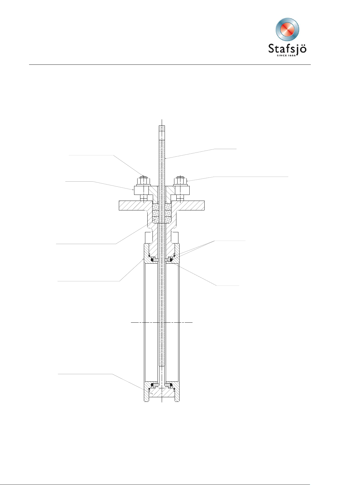
Gland
Valve body
Box packing
Retainer ring
Gate
Stud bolt
Nut and washer
O-ring
Seat
Main components in the Stafsjö knife gate valve XV
Figure 1
2
Document: Maintenance instruction
Product: XV
Issue: 2
Issue date: 2010-10-05
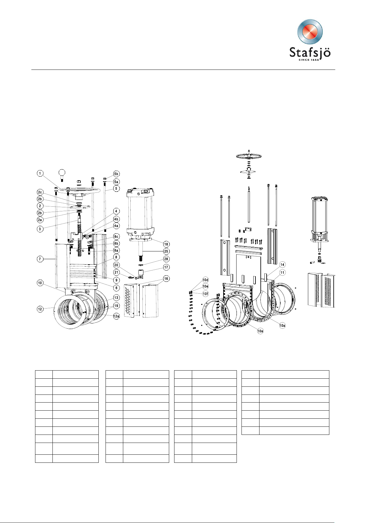
Pos
Part Pos
Part Pos
Part Pos
Part
1
Hand wheel
5a
Washer
10d
Screw 18
Cylinder
2
Yoke 5b
Nut 10e
Washer
19
O-ring
2a
Bearing
6 Gate 10f
Nut 20
Clevis pin
2b
Slide washer
7 Beam 11
Body gasket
21
Split pin
2c
Bearing
8 Gland 12
Retainer ring
25
Piston rod
3
Stem 8a
Stud bolt
12a
Locking screw
28
Locking nut
4
Stem nut
8b
Washer
13
Seat*
*
Recommended spare parts
4a
Washer
8c
Nut 14
Guide strips
4b
Screw 9
Box packing*
16
Gate guard, not
for HW
5
Tie rod
10a
Valve body
17
Gate clevis
Part list of the Stafsjö knife gate valve XV
Figure 2
3
 Loading...