

Page 1
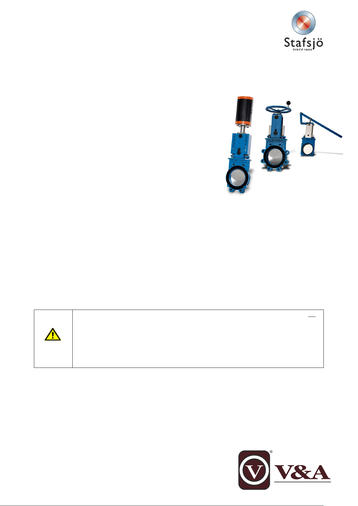
Maintenance instruction for the WB valves
Steps and procedures described in this maintenance instruction are based on a valve which is not
installed in a pipe system.
Before any maintenance begins the valve must be removed from the pipe system and the pneumat-
ic cylinder must be disconnected from the air supply. Follow procedure described in installation and
service instruction for the knife gate valve and its actuator.
Maintenance shall be performed by qualified personal. Qualified are those persons who, due to
experience, can judge the risk and execute the work correctly and who are able to detect and to
eliminate possible risks.
All specifications are subject to change without notice.
This instruction is a step-by-step instruction for maintenance on Stafsjö’s knife gate valves WB, WB 11, WB12 and
WB14.
Following procedures are described in this service instruction:
A. Disassemble parts of the valve.
B. Changing box packing, sealing profile and gate.
C. Torque for gland nuts.
D. Installation of stem and stem nut on hand wheel operated valves.
E. Installation of hand wheel and double acting pneumatic cylinder.
For information on installation procedures and other technical documents,
please see documents available on www.stafsjo.com.
Stafsjö does not accept any responsibility for the product if maintenance on
the knife gate valve is not performed according to this instruction. Neither
does Stafsjö accept any responsibility for the product if it has been mod-
ified from its original condition.
Spare parts
Spare parts may differ depending on valve size and date of manufacturing. Each knife gate valve is identified with a label
containing the article number and serial number. When corresponding with Stafsjö or your local representative, please
have these numbers available. Stafsjö recommends the customer to keep one set of spare parts on stock parts for each
valve type and size.
Spare parts can be ordered from Stafsjö or your local representative. Stafsjö also offers maintenance service of the
valve, either on site at the customer’s plant or at Stafsjö’s workshop. Please contact Stafsjö or your local representative
for further information.
Safety warnings at maintenance
Document: mi-WB, 2013-11-05, issue: 5
Page 2
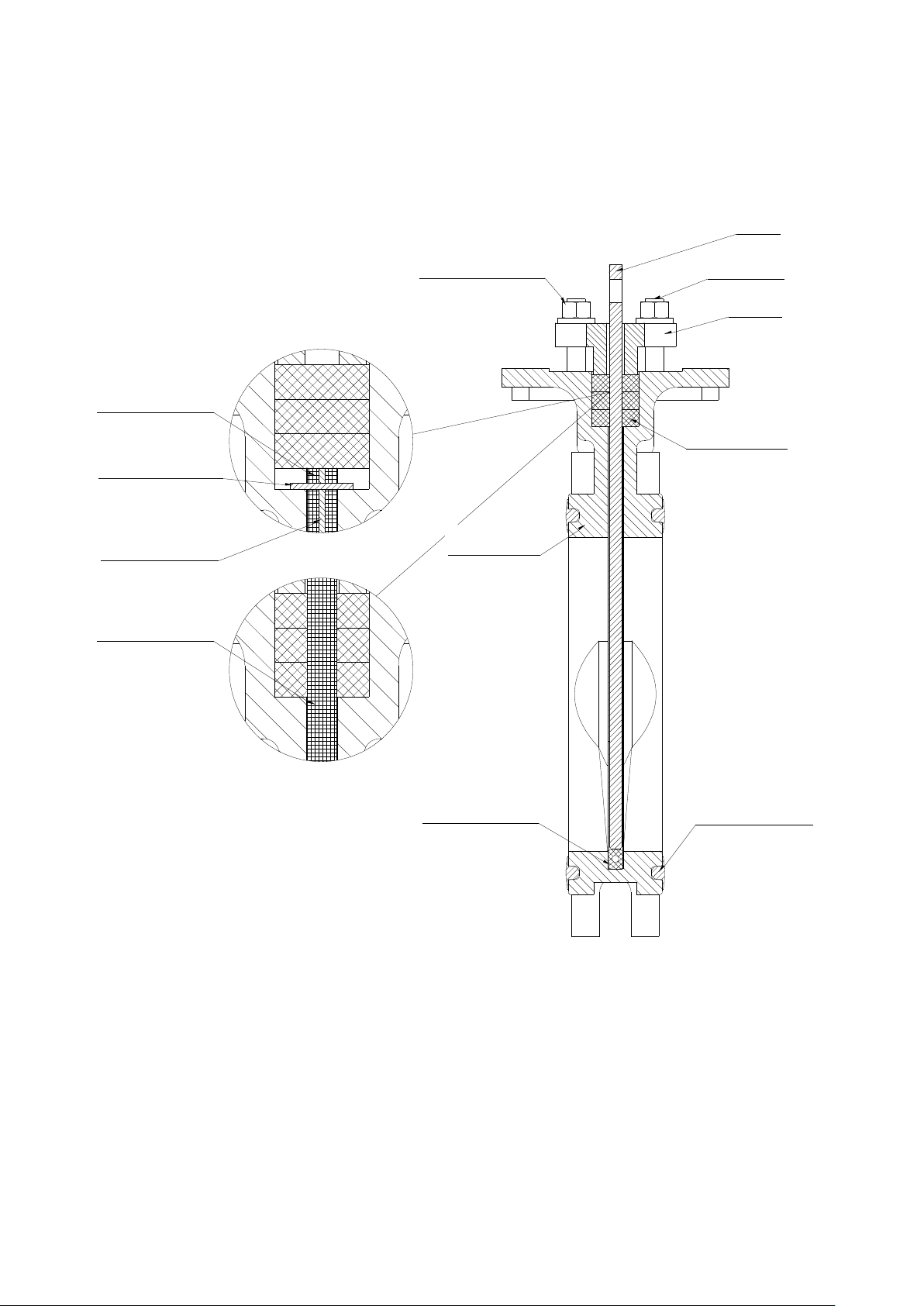
Nut and washer
Valve body
Sealing profile
Gate
Stud bolt
Gland
Box packing
Pin, long
Pin, short
Sealing profile
Flange sealing
Sealing profile
Figure 1: Main components
Nut and washer
Valve body
Box packing
Sealing profile
Flange sealing
Gland
Stud bolt
Gate
Sealing profile
Sealing profile
Pin, long
Pin, short
Maintenance instruction
WB
2
Page 3
Figure 2: part list
Pos
Part
Pos
Part 1 Hand Wheel
8a
Pinn bolt
1d
Washer
8b
Washer
1e
Nut
8c
Nut 2 Yoke
9*
Boxpackning with a box bottom scraper > DN 200
2a
Bearing
10
Valve body
2b
Slide Washer
10c*
Flange sealing
2c
Bearing
13*
Sealing profile
3
Stem
13a*
Pin, long
4
Stem Nut
13b*
Pin, short
4a
Washer
16
Gate guard, not for HW
4b
Bolt
18
Cylinder
6
Gate
20
Bolt/Clevis pin
7
Beam
21
Locking pins
7c
Bolt
20a
Washer
7d
Washer
20b
Nut
7e
Washer
25
Piston rod
7f
Nut
28
Locking nut
7g
Bolt
* Recommended spare parts.
8
Gland
EC pneumatic actuator
AC pneumatic actuator
WB equipped with sealing
profile and separate pins
WB 11, WB14, WB 11k and WB 12 equipped with one
piece molded sealing profile (U-shaped)
Maintenance instruction
WB
3
Page 4

Maintenance instruction
The box packing and sealing profile are often damaged when they are removed from the valve body.
Stafsjö recommends to change box packing and sealing profile if they have been removed from the valve
body.
WB has been available with different types of sealing profiles and box packings. To verify you have correct
spare parts, use the valve’s article number and serial number in correspondence with Stafsjö or your local
representative.
WB
A. Disassemble parts of the valve
To simplify the disassembling of the knife gate, place the valve upright in a screw vice. Large valves shall be placed on a
horizontal work bench. See figure 1 and 2 for identification of the parts in the WB knife gate valve.
1. Open the valve completely.
2. Disassemble the actuator and top.
Hand wheel (1)
a. Demount the hand wheel (1).
b. Loosen the bolts (7g), washers (7e) and nuts (7f).
c. Lift off the bearing (2c), bearing washer (2b), yoke (2), bearing washer (2b) and bearing (2a) from
the stem (3).
d. Loosen the bolts (7c) and washers (7d) and demount the beams (7).
e. Loosen the bolt (4b), washer (4a) from the stem nut (4) and gate (6).
f. Remove the stem (3) and stem nut (4).
AC pneumatic cylinder (18)
a. Loosen the gate guards (16).
b. Loosen the nut (20b), washer (20a) and bolt (20).
c. Keep the cylinder (18) in place and loosen the nuts (7f), bolt (7g) and washer (7e).
d. Remove the cylinder (18).
EC pneumatic cylinder (18)
a. Loosen the gate guards (16).
b. Loosen the locking pins (21) and clevis pin (20).
c. Keep the cylinder (18) in place and loosen the nuts (7f), bolt (7g) and washer (7e).
d. Remove the cylinder (18).
3. Loosen all the nuts (8c) on the gland (8).
4. Lift of the gland (8) from the stud bolts (8a).
5. Remove the box packing braids (9). If the valve with a box bottom scraper, remove that one as well.
6. Clean the box from residues.
7. Remove the gate (6). Inspect it and change it if it has dents and scrapes, which will affect and wear out
the box packing (9) and the sealing profile (13).
8. Remove the sealing profile (13).
9. Clean the sealing profile groove from residues.
B. Changing box packing, sealing profile and gate
4
Page 5

Maintenance instruction
Sealing profile (10)
Gate (6)
Bump
Before assembling starts, check the gate (6) for damages such as dents and scrapes. If the gate is damaged it can wear out the box packing (9), the sealing profile (13) and leakage can occur because of this.
To ensure optimal operation, Stafsjö recommends changing the gate if it is damaged.
Short pin (13b)
Sealing profile (13)
Long pin (13a)
Bump
WB
Before assembling make sure you have:
For WB equipped with sealing profile and separate pins
• Sealing profile (13) which consists of a rubber profile, one long
pin (13a) and two short pins (13b). Put the long pin into the sealing
and make sure it is centred. The short wires prevent the sealing
profile from being pushed into the valve body by the gate (6).
• Glue of Loctite 480 type. This is a quick-cure type of glue, means
that you have short time before it cure.
• Box packing (9), i.e. three pieces of braids.
For WB 11, WB14 and WB 12 equipped with one piece moulded sealing profile (U-shaped)
• One piece moulded sealing profile (U-shaped) (13).
• Box packing (9), i.e. 6 pieces of braids. If it is supplied with a box bottom scraper, have that also avail-
able.
Additional equipment for both types
• Synthetic lubricator (Multipurpose Grease OKS 1110 or similar grease approved for EPDM and Nitril)
• A plastic surfaced hammer and/or a pneumatic cylinder to push down the gate in closed position.
• Necessary lifting equipment for valves > DN 300.
Follow steps below to change box packing, sealing profile and gate:
1. Make sure that the valve body’s gate groove is cleaned and free from grease and residues.
2. Put the valve in a vertically up-right position in a screw vice. If the valve is supplied with a sealing profile and separate pins, then use the gate as a forming tool for the sealing profile.
3. Put grease on the short end of the gate (6)
3a. For WB equipped with sealing profile and separate pins only:
Take the complete sealing profile (13) and add glue in a zigzag way on the “backside” (opposite side to
the bump). After glued the sealing you have approximately 40 seconds until the glue starts to
cure. The time for curing speeds up when the seal is mounted in the valve body. Be quick.
4. Take the sealing profile and put it into the valve’s gate groove from
the top of the valve. Make sure it is even above the stuffing box
bottom on both sides in the valve.
4a. For WB equipped with sealing profile and separate pins only:
The bump of the sealing profile must be centered and it shall face
the gate (6).
5. Push down the gate (6) to the bottom (100% closed position) of
the valve body (10) by using your own weight or use a plastic surfaced hammer. From DN 300 you might have to be two persons to
do this or use a pneumatic cylinder to push down the gate. Check
that the gate (6) is centered in the valve body (10) according to the
sealing profile (13), see picture to the right.
6. Let the gate stay in closed position for approximately 4 min.
7. Add box packing braids.
7a. For WB equipped with sealing profile and separate pins:
If the valve shall be equipped with a box bottom scraper, add this
first in the box bottom and then add three layers of box packing braids on top of this (9).
Make sure that each layers’ braid ends is placed on the opposite long side of the previous layer. Use a
blunt tool in plastic or wood and a hammer to push the braid into the box.
7b. For WB 11, WB14 and WB 12 equipped with one piece molded sealing profile (U-shaped):
5
Page 6

Maintenance instruction
3
1
2
4
The box packing may start to leak when the system is pressurised and the temperature increases. This is
caused by the box packing which is a soft material that moves depending on pressure and temperature
and when the valve is operated. If the box packing leaks, retighten the gland nuts (8c) gradually and
crosswise according to section 3.3.
Do not tighten the screws too hard, since they shall be fully tightened after the complete hand wheel is
assembled
Recommended maximum torque
DN
Nm
lbf x ft
50-80
20
15
100-150
25
18
200-300
30
22
350-
35
26
WB
If the valve shall be equipped with a box bottom scraper, add these first in the box bottom and then add
three layers of braids on each side of the gate (totally 6 pcs. of braids). To make sure the valve keeps
tight during operation, make sure the braid ends reaches each stuffing box corner.
8. Install the gland (8), washers (8b) and nuts (8c). Tighten the nuts gradually and crosswise (see section
C) and make sure that the gland is centered in the box and has an equal distance from the gate all
around. Use locking nuts. Check that there is no metal contact between the gland (8) and the gate
(6).
C. Torque for gland nuts
The torque TG in the table below is a recommended value for tightening the gland nuts (8c) when a new box packing has
been installed and during operation if the gland box is leaking. Each nut shall be tightened gradually and crosswise until
the leakage stops, see figure and table below. Check that there is no metal contact between the gland (8) and the gate
(6).
If the gland nuts are tightened to hard, it shortens the lifetime of the box packing and the force needed to operate the
valve will increase.
D. Installation of stem and stem nut on hand wheel operated valves
1. Lubricate the thread on the stem (3) with grease and screw on the stem nut (4).
2. Mount the stem nut (4) with the stem (3) on the gate (6) with the washers (4a) and screws (4b).
3. Install hand wheel actuator according to section E.
E. Installation of hand wheel and double-acting pneumatic cylinder
1. Mount the beam (7) on the top of the valve body (10) with the bolts (7c) and the washers (7d).The holes are
placed on different distances from the short side of the beam. The side of the beam with the longest distance
between the hole and the short side shall be placed against the top of the valve body (10).
2. Install the actuator.
Hand wheel
a. Mount the lower bearing (2a) and the bearing washer (2b) on the stem (3).
b. Mount the yoke (2) on the beams (7). Centre the stem (3) with the lower bearing (2a) and attach the
yoke by slightly tighten the bolts (7g), nuts (7f) and washers (7e).
c. Rotate the stem (3) and make sure the lower bearing (2a) connects to the yoke (2).
d. Mount the top bearing washer (2b) and bearing (2c) on the stem (3).
e. Carefully tighten the bolts (4b) on the stem nut (4).
6
Page 7

Maintenance instruction
Danger
A knife gate valve with cylinder shall be operated only if all gate guards are installed correctly. The
user’s life and health is at stake if this is not followed. All other handling is the responsibility of the
user.
WB
f. Tighten the bolts (7g), nuts (7f) and washers (7e) on the yoke.
g. Attach the hand wheel (1) and lock it with washer (1d) and nut (e)
Pneumatic cylinder AC
a. Mount the pneumatic cylinder on the beams (7) and attach it by slightly tighten the bolts (7g), nuts (7f)
and washers (7e).
b. Attach the piston rod (25) to the gate with bolt (20), washer (20a) and nut (20b).
c. Tighten the bolts (7g), nuts (7f) and washers (7e).
d. Open the valve completely by gently operating the pneumatic cylinder (18). In this position, the bolts
(4b) should be in the centre of the upper hole in the beam (7).
e. Install the gate guards (16).
f. Install black caps in the holes of the beam if limit switches is not used.
Pneumatic cylinder EC
a. Mount the pneumatic cylinder on the beams (7) and attach it by slightly tighten the bolts (7g), nuts (7f)
and washers (7e).
b. Attach the gate clevis (17) to the gate with the clevis pin (20) and the split pins (21).
c. Tighten the bolts (7g), nuts (7f) and washers (7e).
d. Open the valve completely by gently operating the pneumatic cylinder (18). In this position, the clevis
pin (20) should be in the centre of the upper hole in the beam (7). If it is not, close the valve, demount
the split pins (21) and clevis pin (20) and adjust the gate clevis (17) on the piston rod (25) until the
clevis pin (20) is in the centre of the upper hole in the beam when the valve is open.
e. When the gate clevis is in correct position, lock the gate clevis (17) with the locking nut (28).
f. Install the gate guards (16).
g. Install black caps in the holes of the beam if limit switches are not used.
3. Test the function of the knife gate valve.
4. Install the knife gate valve in the system according to Stafsjö’s installation and service instructions.
5. Operate the valve a few times before the system is pressurized.
 Loading...