

Page 1
Document: Maintenance instruction
Product: SLV, SLF, SLH, SLX
Issue: 3
Issue date: 20150227
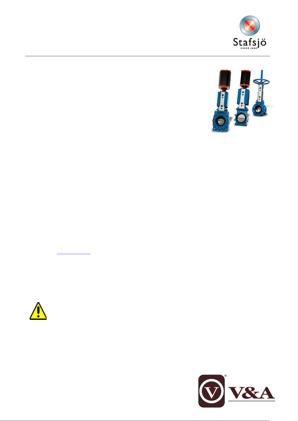
Maintenance instruction for SLV, SLF, SLH and SLX
This maintenance instruction is a step-by-step instruction for service and
maintenance on Stafsjö’s knife gate valve SLV, SLF, SLH and SLX.
Following procedures are described in this service instruction:
A. Change of seat
B. Change of gate and box packing
C. Change of box packing when the valve is installed in a system
D. Torque for nuts on gland
E. Change from hand wheel (HW) to pneumatic cylinder (EC) when
the valve is installed in a system
For procedures A and B the knife gate valve must be uninstalled from the system.
For information on installation and operation procedures or detailed technical data, please see documents
available on www.stafsjo.com.
Each knife gate valve is identified with a label containing the article number and serial number. When
corresponding with Stafsjö or your local representative, please have these numbers available.
Stafsjö does not accept any responsibility for the product if service and maintenance on the knife gate
valve is not performed according to this instruction. Neither does Stafsjö accept any responsibility for the
product if it has been modified from its original condition.
Spare parts
Recommended spare parts are described in spare part data sheets for each knife gate valve typ on
www.stafsjo.com. Stafsjö recommends the customer to keep one set of spare parts for each valve type
and size in store.
Spare parts can be ordered from Stafsö or your local representative. Spare part data sheets and addresses are available on www.stafso.com
Safety information
No work is allowed on the knife gate valve when the system is pressurised or the actuator is
connected. The system must be free from pressure and empty. Actuator and accessories must
be disconnected before any work begins.
All gate guards must be installed on the valve after maintenance.
Information is only for informational purpose. All specifications are subject to change without notice.
Page 2
Document: Maintenance instruction
Product: SLV, SLF, SLH, SLX
Issue: 2
Issue date: 2012-11-05
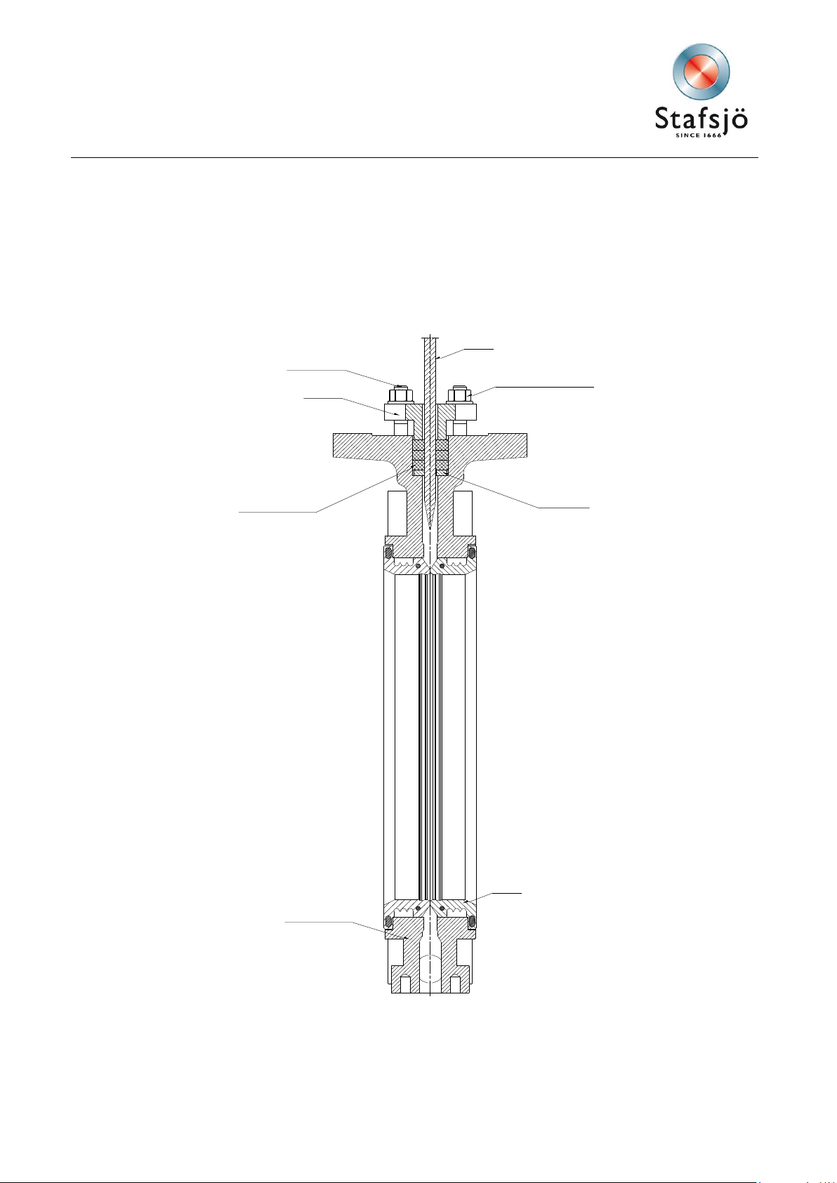
Gate
Nut and washer
Seat
Scraper
Valve body
Box packing
Gland
Stud bolt
Main components of Stafsjö’s SLV, SLF, SLH and SLX
2
Page 3

Document: Maintenance instruction
Product: SLV, SLF, SLH, SLX
Issue: 2
Issue date: 2012-11-05
Pos.
Detail
Pos.
Detail
Pos.
Detail
Pos.
Detail
1
Hand wheel
5b
Nut
10/a/b
Valve bodyd
55
Plug 2 Yoke
6
Gate
11
Body gasket
56
Locking pin
2a
Bearing
7
Beam
13
Seat
57
Stem protection
2b
Slide washer
7c
Screw
16
Gate guard not for HW
62
Wedge
2c
Bearing
7d
Washer
17
Gate clevis
63
Stemtube
2d
Washer
7e
Washer
18
Cylinder
64
Plug
2e
Locking nut
7f
Nut
20
Clevis pin
65
Gate indicator
3
Stem with gate clavis
7g
Screw
21
Split pin
3a
Stop washer
8
Gland
25
Piston rod
3b
Screw
8a
Stud bolt
28
Locking nut
3c
Washer
8b
Washer
47
Gasket
4
Stem nut
8c
Nut
54
Bottom cover
5
Tie rod
9
Box packing
54a
Screw
5a
Washer
9a
Box bottom scraper
54b
Washer
Part list of Stafsjö’s SLV, SLF, SLH and SLX (Figure 2)
3
Page 4

Document: Maintenance instruction
Product: SLV, SLF, SLH, SLX
Issue: 2
Issue date: 2012-11-05
Hand wheel (1)
a. Demount the hand wheel (1).
b. Loosen the nuts (5b).
c. Lift off the bearing (2c), bearing washer (2b), yoke (2), bearing washer (2b) and
bearing (2a) from the stem (3).
d. Demount the beams (7) and tie rods (5).
e. Loosen the screw (4b) from the stem nut (4) and gate (6).
f. Lift off the stem (3) and stem nut (4).
Pneumatic
cylinder (18)
a. Loosen the gate guards (16).
b. Demount the split pins (21) and the clevis pin (20).
c. Loosen the nuts (5b) keeping the cylinder in place.
d. Lift off the cylinder (18).
e. Remove the beam (7) and tie rods (5) from the valve.
Picture 3
A. Change of seat
Place the valve horizontally for simple change of seats.
1. Open the valve.
2. Remove the seat (13).
3. Check the gate (6) for damages such as dents and scratches. If the gate is damaged it can wear out
the box packing (9) and the seat (13), which could cause leakage. Stafsjö recommends changing the
gate if it is damaged to ensure the proper operation of the valve.
4. Clean the area of the seat and the valve body.
5. Lubricate the seats with grease, OKS1110 or similar.
6. Place the new seats (13) in the bore of the valve body (10).
7. Install the valve in open position into the system. See operating instruction for further information.
8. Operate the valve a few times before the system is pressurised.
B. Change of gate and box packing
Place the valve upright, in for example a screw vice, for simple change of the gate and box packing. Large
valves should be placed horizontally on a work bench.
1. Close the valve completely.
2. Demount the actuator and top.
3. Loosen the nuts (8c) on the gland (8).
4. Lift of the gland (8) from the stud bolts (8a).
5. Remove the box packing braids (9) and the box bottom scraper (9a).
6. Clean the box from residues.
7. Remove the gate (6).
8. Remove the seats (13). The procedure is described in section A.
9. Remove the plugs (55)
10. Use a plastic or wooden round bar and put into the purge ports to
make a stop for the gate, see picture 3.
11. Place the new gate (6) into the valve body.
4
Page 5

Document: Maintenance instruction
Product: SLV, SLF, SLH, SLX
Issue: 2
Issue date: 2012-11-05
Hand wheel (1)
g. Demount the hand wheel (1).
h. Loosen the nuts (5b).
i. Lift off the bearing (2c), bearing washer (2b), yoke (2), bearing washer (2b) and
12. Place the box bottom scraper (9a) in the bottom of the gland box. Install the first braid (9) on one of
the long sides of the gate (6). Use a blunt tool in plastic or wood and a hammer to push the braid into
the box. Make sure that the braid ends meets properly. It is important to push the first braid evenly into
the bottom of the box. The joint of the second and third braid must be placed on the opposite long side
of the joint of the previous braid, not on top of each other.
13. Install the gland (8) on the stud bolts (8a).
14. Add washers (8b) and nuts (8c).
15. Install the seats (13), see section A.
16. Put pressure on the gland (8) by tightening the nuts (8c) gradually and crosswise, see figure 4. The
box packing must be
equally compressed all around. Recommended torque for gland nuts, see section D.
17. The gland (8) must put a uniform pressure on the box packing (9). The gland (8) must also be in line
with the gate (6) with the same distance between the gland and the gate all around. Check that there
is no metal contact between the gland (8) and the gate (6).
18. Remove the round bar from the purge ports and install the plugs (55).
19. Install the other components in reversed order according to step 2.
20. Make a function test before the valve is put into operation.
21. Make sure that the valve is fully open.
22. Install the valve in the system according to instructions in the operating instruction.
23. Operate the valve a few times before the system is pressurised.
Note:
The box packing may start to leak when the system is pressurised and the temperature increases. This is
caused due to that the box packing, which is a soft material, moves depending on pressure and temperature when the valve is operated. If the box packing is leaking, tighten the gland nuts (8c) gradually and
crosswise according to chapter D.
C – Change of box packing when the valve is installed in a system
No work is allowed on the Stafsjö knife gate valve when the system is pressurised or the automatic
actuator is connected. The system must be empty and free from pressure before any work begins
and the actuator and accessories must be disconnected.
Work on the knife gate valve when the system is under pressure can cause damages on persons
and equipment.
Check that the system is free from pressure by:
o Observing the pressure measurement on the system
o Opening the drain on the pipe
When the system is free from pressure and empty:
1. Check the gate (6) visually for damages such as dents and scratches. If the gate is damaged it can
wear out the box packing (9) and the seats (13), which could cause leakage. Stafsjö recommends
changing gate if it is damaged in order to ensure proper operation. Procedure of changing the gate is
described in section B.
2. Close the valve completely.
3. Demount the actuator and top.
5
Page 6

Document: Maintenance instruction
Product: SLV, SLF, SLH, SLX
Issue: 2
Issue date: 2012-11-05
3
1
2
4
bearing (2a) from the stem (3).
j. Demount the beams (7) and tie rods (5).
k. Loosen the screw (4b) from the stem nut (4) and gate (6).
l. Lift off the stem (3) and stem nut (4).
Pneumatic
cylinder (18)
f. Loosen the gate guards (16).
g. Demount the split pins (21) and the clevis pin (20).
h. Loosen the nuts (5b) keeping the cylinder in place.
i. Lift off the cylinder (18).
j. Demount the beam (7) and tie rods (5) from the valve.
TG
DN
Nm
lbf x ft
50 – 80
25
18
100 – 150
30
22
200 - 600
35
26
Figure 4: Tighten gland nuts crosswise
4. Loosen the nuts (8c) on the gland (8).
5. Lift of the gland (8) from the stud bolts (8a).
6. Remove the box packing braids (9) and the box bottom scraper (9a).
7. Clean the box from residues.
8. Push down the box bottom scraper (9a) into the bottom of the gland box. Install the first braid (9) on
one of the long sides of the gate (6). Use a blunt tool in plastic or wood and a hammer to push the
braid into the box. Make sure that the braid ends meets properly. It is important to push the first braid
evenly into the bottom of the box. The joint of the second and third braid must be placed on the opposite long side of the joint of the previous braid, not on top of each other.
9. Place the gland (8) on the stud bolts (8a).
10. Add the washers (8b) and nuts (8c).
11. Put pressure on the gland (8) by tightening the nuts (8c) gradually and crosswise, see figure 4. The
box packing must be equally compressed all around. Recommended torque for gland nuts, see chapter D.
12. The gland (8) must put a uniform pressure on the box packing (9). The gland (8) must also be in line
with the gate (6) with the same distance between the gland and the gate all around. Check that there
is no metal contact between the gland (8) and the gate (6).
13. Operate the valve a few times before the system is pressurised.
Note:
The box packing may start to leak when the system is pressurised and the temperature increases. This is
caused due to that by the box packing, which is a soft material, moves depending on pressure and temperature and when the valve is operated. If the box packing is leaking, tighten the gland nuts (8c) gradually
and crosswise according to chapter D.
D - Torque for gland nuts
The torque TG in the table below is a recommended value
for tightening the gland nuts (8c).
If the box packing is leaking, tighten the gland nuts (8c).
Each nut shall be tightened gradually and crosswise until
the leakage stops and the gate moves smoothly without tipping in the opening or closing instant.
If the gland nuts are tightened to hard, it shortens the lifetime of the box packing and increases the force
needed to operate the valve.
6
Page 7

Document: Maintenance instruction
Product: SLV, SLF, SLH, SLX
Issue: 2
Issue date: 2012-11-05
Check that the gland (8) is in level to the top of the valve body (10). Check that there is no metal contact
Picture 5
between the gland (8) and the gate (6).
E – Change from hand wheel (HW) to pneumatic cylinder (EC) when the valve is in-
stalled in a system
No work is allowed on the Stafsjö knife gate valve when the system is pressurised or the automatic
actuator is connected. The system must be empty and free from pressure before any work begins
and the actuator and accessories must be disconnected.
Work on the knife gate valve when the system is under pressure can cause damages on persons
and equipment. Check that the system is free from pressure by:
o Observing the pressure measurement on the system
o Opening the drain on the pipe
Before installing a pneumatic cylinder onto the valve, you must always check:
• That the pneumatic cylinder is correct in size regarding the size SLV valve.
• That the air supply to the cylinder is correct regarding, quality, pressure and flow.
1. Close the valve completely.
2. Demount the hand wheel, se section B: 2.
3. Screw the locking nut (28) and the gate clevis (17) halfway
up on the threaded part of the piston rod (25).
4. Mount the cylinder (18) on top of the beams and fixate it with
washers (5a) and nuts (5b). Make sure you have necessary
support for the pneumatic cylinder.
5. Attach the gate clevis (17) to the gate with clevis pin (20)
and the split pins (21).
6. Open the valve completely by gently operating the pneumatic cylinder (18). In this position, the clevis pin should be
in centre of the upper limit switch hole in the beam (7), see
picture 5. If it is not, close the valve and demount the split
pins (21) and clevis pin (20). Adjust the gate clevis (17) on
the piston rod (25) until it is in the centre of the upper limit
switch hole in the beam when the valve is completely
open.
7. Lock the gate clevis (17) with the locking nut (28).
8. Mount the gate guards (16).
9. Before the actuation test are carried out make sure:
• The pneumatic cylinder is correctly mounted on the knife gate valve with adjusted cylinder stroke.
• The air connected to the cylinder does not exceed maximum allowed pressure of 10 bar.
• The air pipe connected to the cylinder has the right size and is correctly installed.
• The knife gate valve and pneumatic cylinder have sufficient supported to avoid tensions.
10. Operate the valve a few times before the system is pressurised.
 Loading...